US3858873A - Weight lifting exercising devices - Google Patents
Weight lifting exercising devicesDownload PDFInfo
- Publication number
- US3858873A US3858873AUS360590AUS36059073AUS3858873AUS 3858873 AUS3858873 AUS 3858873AUS 360590 AUS360590 AUS 360590AUS 36059073 AUS36059073 AUS 36059073AUS 3858873 AUS3858873 AUS 3858873A
- Authority
- US
- United States
- Prior art keywords
- resistance
- force
- resolving
- body part
- force receiving
- Prior art date
- Legal status (The legal status is an assumption and is not a legal conclusion. Google has not performed a legal analysis and makes no representation as to the accuracy of the status listed.)
- Expired - Lifetime
Links
- 230000005484gravityEffects0.000claimsdescription9
- 210000001087myotubuleAnatomy0.000claimsdescription7
- 230000000087stabilizing effectEffects0.000claimsdescription6
- 210000003205muscleAnatomy0.000abstractdescription24
- 210000001364upper extremityAnatomy0.000description9
- 210000000245forearmAnatomy0.000description3
- 230000000694effectsEffects0.000description2
- 238000000034methodMethods0.000description2
- 206010043268TensionDiseases0.000description1
- 238000005452bendingMethods0.000description1
- 230000037086body physiologyEffects0.000description1
- 239000003795chemical substances by applicationSubstances0.000description1
- 230000007423decreaseEffects0.000description1
- 229910003460diamondInorganic materials0.000description1
- 239000010432diamondSubstances0.000description1
- 210000003414extremityAnatomy0.000description1
- 238000012986modificationMethods0.000description1
- 230000004048modificationEffects0.000description1
- 230000037191muscle physiologyEffects0.000description1
- 230000002035prolonged effectEffects0.000description1
- 230000000284resting effectEffects0.000description1
- 239000003381stabilizerSubstances0.000description1
Images


Classifications
- A—HUMAN NECESSITIES
- A63—SPORTS; GAMES; AMUSEMENTS
- A63B—APPARATUS FOR PHYSICAL TRAINING, GYMNASTICS, SWIMMING, CLIMBING, OR FENCING; BALL GAMES; TRAINING EQUIPMENT
- A63B21/00—Exercising apparatus for developing or strengthening the muscles or joints of the body by working against a counterforce, with or without measuring devices
- A63B21/40—Interfaces with the user related to strength training; Details thereof
- A63B21/4041—Interfaces with the user related to strength training; Details thereof characterised by the movements of the interface
- A63B21/4047—Pivoting movement
- A—HUMAN NECESSITIES
- A63—SPORTS; GAMES; AMUSEMENTS
- A63B—APPARATUS FOR PHYSICAL TRAINING, GYMNASTICS, SWIMMING, CLIMBING, OR FENCING; BALL GAMES; TRAINING EQUIPMENT
- A63B21/00—Exercising apparatus for developing or strengthening the muscles or joints of the body by working against a counterforce, with or without measuring devices
- A63B21/06—User-manipulated weights
- A63B21/0615—User-manipulated weights pivoting about a fixed horizontal fulcrum
- A—HUMAN NECESSITIES
- A63—SPORTS; GAMES; AMUSEMENTS
- A63B—APPARATUS FOR PHYSICAL TRAINING, GYMNASTICS, SWIMMING, CLIMBING, OR FENCING; BALL GAMES; TRAINING EQUIPMENT
- A63B21/00—Exercising apparatus for developing or strengthening the muscles or joints of the body by working against a counterforce, with or without measuring devices
- A63B21/15—Arrangements for force transmissions
- A63B21/151—Using flexible elements for reciprocating movements, e.g. ropes or chains
- A63B21/154—Using flexible elements for reciprocating movements, e.g. ropes or chains using special pulley-assemblies
- A63B21/155—Cam-shaped pulleys or other non-uniform pulleys, e.g. conical
- A—HUMAN NECESSITIES
- A63—SPORTS; GAMES; AMUSEMENTS
- A63B—APPARATUS FOR PHYSICAL TRAINING, GYMNASTICS, SWIMMING, CLIMBING, OR FENCING; BALL GAMES; TRAINING EQUIPMENT
- A63B23/00—Exercising apparatus specially adapted for particular parts of the body
- A63B23/035—Exercising apparatus specially adapted for particular parts of the body for limbs, i.e. upper or lower limbs, e.g. simultaneously
- A63B23/03516—For both arms together or both legs together; Aspects related to the co-ordination between right and left side limbs of a user
- A63B23/03525—Supports for both feet or both hands performing simultaneously the same movement, e.g. single pedal or single handle
- A—HUMAN NECESSITIES
- A63—SPORTS; GAMES; AMUSEMENTS
- A63B—APPARATUS FOR PHYSICAL TRAINING, GYMNASTICS, SWIMMING, CLIMBING, OR FENCING; BALL GAMES; TRAINING EQUIPMENT
- A63B23/00—Exercising apparatus specially adapted for particular parts of the body
- A63B23/035—Exercising apparatus specially adapted for particular parts of the body for limbs, i.e. upper or lower limbs, e.g. simultaneously
- A63B23/12—Exercising apparatus specially adapted for particular parts of the body for limbs, i.e. upper or lower limbs, e.g. simultaneously for upper limbs or related muscles, e.g. chest, upper back or shoulder muscles
- A63B23/1245—Primarily by articulating the shoulder joint
- A—HUMAN NECESSITIES
- A63—SPORTS; GAMES; AMUSEMENTS
- A63B—APPARATUS FOR PHYSICAL TRAINING, GYMNASTICS, SWIMMING, CLIMBING, OR FENCING; BALL GAMES; TRAINING EQUIPMENT
- A63B21/00—Exercising apparatus for developing or strengthening the muscles or joints of the body by working against a counterforce, with or without measuring devices
- A63B21/40—Interfaces with the user related to strength training; Details thereof
- A63B21/4027—Specific exercise interfaces
- A63B21/4033—Handles, pedals, bars or platforms
- A63B21/4035—Handles, pedals, bars or platforms for operation by hand
- A—HUMAN NECESSITIES
- A63—SPORTS; GAMES; AMUSEMENTS
- A63B—APPARATUS FOR PHYSICAL TRAINING, GYMNASTICS, SWIMMING, CLIMBING, OR FENCING; BALL GAMES; TRAINING EQUIPMENT
- A63B2208/00—Characteristics or parameters related to the user or player
- A63B2208/02—Characteristics or parameters related to the user or player posture
- A63B2208/0228—Sitting on the buttocks
- A63B2208/0233—Sitting on the buttocks in 90/90 position, like on a chair
Definitions
- ABSTRACTAn apparatus for the development of body parts and muscles effecting the movement ofa users body parts.
- the apparatusincludes a frame on which is pivotally mounted a force applying member against which a body part maybe placed and urged for purposes of developing said body part and muscles.
- the useris positioned on the front side of the frame during an exercise program.
- the apparatusalso includes a weight pivotally mounted on the rear side of the frame and a force resolving spiral means rigidly connected to the force applying member for rotation therewith whereby the pull on the weight mass is continuously varied over the full range of rotation of said force applying member to produce a varying resistance force in direct opposition to the force applied to the force applying member by a body part and thereby to stress and develop said body part and muscles.
- the resolving spiralis in the form of one or more pulleys which continuously resolves the force of the weight mass to thereby provide optimum stress for developing the muscles. The effort of continuously exposing the body part undergoing an exercise to a varying force over the full range of movement will cause the muscle effecting movement of said body part to be subjected to optimum development conditions.
- a simple and well known form of body building exerciseis the curl, the movement of which is rotational throughout a range of movement of approximately 160.
- the movementis almost perfectly horizontal, straight forward; approximately mid way through this exercise the movement is vertical, straight up; and at the end of the exercise the movement is approximately horizontal again, but in the opposite direction.
- the resistanceis always vertical in a straight down direction. From this it is seen that although the resistance remains constant, it would seem to become heavier as the movement progresses from the starting position to the midpoint and seem to become lighter thereafter. In the normal finishing position of the curl, there is literally no resistance.
- the present inventionrelates to a new exercising machine based upon the concept that the greatest rate of development of body parts and muscles effecting the movement thereof is achieved by providing the body part and muscle involved in a particular exercise with a balanced resistance over the full range of motion of the involved body part and muscle.
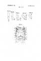
- FIGS. lA-Eshow a sequence of arm positions in a curl exercise
- FIG. 2shows a front elevational view of the machine according to this invention with an exerciser outlined in phantom as being seated on and strapped to the machine in an initial position prior to using the machine;
- FIG. 3shows a side elevational view of the machine according to this invention with the exerciser preparing to adjust the force applying lever to the position in which the body part to be exercised may be applied thereagainst;
- FIG. 4shows a side elevational view of the machine acdording to this invention with the exerciser having adjusted the force applying lever to the position in which the body part to be exercised may be applied thereagainst by lowering the forward end of a treadle;
- FIG. 5shows a side elevational view of the machine according to this invention with the exerciser having placed the body parts to be exercised against the force applying lever;
- FIG. 6shows a side elevational view of the machine according to this invention with the exerciser having removed his feet from the adjustment treadle;
- FIG. 7shows a side elevational view of the machine according to this invention with the exerciser allowing his arms to move back to initiate a cycle of exercise;
- FIG. 8shows a side elevational view of the machine according to this invention with the exerciser having moved his arms forward to about the midpoint of a cycle of exercise;
- FIG. 9shows a side elevational view of the machine according to this invention with the exerciser having brought his arms forward to the other end of the exercise cycle and;
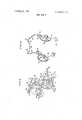
- FIG. 10shows a view in perspective generally from the rear of the force applying lever, resolving spiral pulley and counterweight assembly.
- FIGS. 1 A-Eshow a sequence of arm positions during a curling exercise
- FIG. 1Ashows the initial position of the exercise
- the lower armis in line with the upper arm and therefore produces zero moment about X which marks the pivot point between the upper and the lower arms.
- moment armsof eight inches, twelve inches, and six inches, respectively, are effected about the pivot point X.
- FIG. 1Eshows the end of the exercise as shown in FIG. 1E, there is again zero moment arm about the pivot point X since the weight at the end of the lower arm is once again in vertical alignment with the pivot point X.
- the novel exercising machineis in the form of a pull-over machine which comprises a frame 10 having a pair of parallel front legs 12 extending upwardly and to the rear.
- Each of the front legs 12includes a rearwardly directed, angled extension 14'.
- Extending transversely of the machineis a bar 15 which is integral with the ends of extensions 14 to provide rigidity to the frame 10 thereat.
- Approximately midway between the bottom of each of the front legs 12 and the intersection point of the extension 14 with the front legs 12is a downwardly and rearwardly extending rear leg 16.
- a horizontal bar 18connects each of the front legs 12 to a rear leg 16 to provide the frame with rigidity.
- a generally vertically extending bar 20connects each of the angled extensions 14 to a rear leg 16 to provide additional rigidity to the frame 10.
- Extending generally parallel to and above each of the bars 18is an upper bar 22 integral with a front leg 12 and a rear leg 16. Integral with each of the bars 18 is a transversely extending horizontal bar 24. Extending rearwardly from the midpoint of the transversely extending bar 24 to opposite bars 18 is a pair of diagonal bars 27.
- a load or resistance weight tray assembly 30includes a pair of parallel arms 32 extending forwardly therefrom to each of the front legs 12 which are pivotally secured thereto by pins 34.
- the tray assembly 30includes a pair of parallel weight retaining posts 36 which are adapted to pass through perforated load or resistance weight members 38 which are removably held thereby. Additional load or resistance weight members may be added thereto if desired.
- Fixed to the underside of the weight tray assembly 30 and midway between posts 36is a generally U-shaped rail element 39.
- Brackets 40Extending rearwardly from the weight tray assembly 30 is a pair of brackets 40 each of which supports a bearing post assembly 42 for a pair of rotatable lifting pulleys 43 which are substantially in the same plane.
- a pair of parallel redirectional pulleys 44are rotatably supported adjacent the free end of the extensions 14 by pins 46 and brackets 48.
- a pair of parallel spiral pulleys 50each having a plurality of spokes 52 and a hub 54 integral therewith are rotatably supported at the top of front legs 12 and adapted to rotate about the axis of pins 56.
- the free end of each leg 64has a reversely extending angled portion 66 which ultimately extends transversely of the machine as a stabilizing bar 68 integrally connecting opposite angled portions 66 and providing a deformed clearance therebetween.
- An elbow pad 72 constituting force receiving meansis secured to each bracket
- a yoke 74Integral with and extending down from the bottom of seat support 26 is a yoke 74 on which is pivotally secured a treadle 76 by pins 78.
- the treadle 76has an angled front extension 80 through which extends a transverse bar 82.
- At the rear end of the treadle 76is an abutment member 84 adapted to contact rail 39.
- a two-piece seat belt 86is fixed to each bar 22 by pin 28.
- an exerciserTo operate the machine an exerciser first seats himself in the machine and straps himself thereto with twopiece belt 86 as shown in FIG. 2. At this time the force applying lever assembly 60 is up and behind the exerciser as best seen in FIG. 3. The exerciser then places his feet on the transverse bar 82 at the end of the front extension 80 of treadle 76 preparatory to raising the weight tray assembly 30. The exerciser then brings his feet to the ground to raise the load or resistance weight tray assembly 30 as the abutment member 84 at the rear end of treadle 76, which is pivoted at 78, is brought against the rail 39 at the underside of the weight tray assembly 30 as shown in FIG. 4. As the weight tray assembly 30 is raised to the position shown in FIG. 4, each counterweight 57 drops from the position shown in FIG.
- each spiral pulley 50 and force applying lever assembly 60both of which are interconnected to the counterweight 57 by the hub 54 rotatably supported at the top of the front legs 12 by pins 56 to rotate in a clockwise direction to the position shown in FIG. 4.
- the exercisermay now place the elbow portion of his upper arms against the force receiving pads 72 as shown in FIG. 5.
- the upper armsare regarded as prime body parts and the shoulder area of each arm is considered as a prime body joint.
- the exerciserremoves his feet from the transverse bar 82 to allow the rear end of the treadle 76 to drop to the ground.
- the weight tray assembly 30is suspended in mid air by virtue of the cable 58 which passes under the pair of pulleys 43, over the pair of re-directional pulleys 44 and is secured to the surface of spiral pulleys 50.
- Various positions of the force applying lever assembly 60are now determined by the force applied thereto by the exercisers upper arms in opposition to gravity pull of the weight tray assembly 30 as resolved by the spiral pulleys 50 along portions of cable 58 emanating from the surface of pulleys 50 in tension. It is noted here that the only force applied to the lever assembly 60 by the exerciser is at the elbow pads 72. No force is applied to the leg 64 or at the angled portions 66 of the lever assembly 60 by the forearms and hands of the exerciser.
- the location of the forearms and handsare irrelevant as long as they do not interfere with the force applied by the upper arms.
- the principal function of the legs 64is to provide a resting place for the forearms of the exerciser and to support the angled portions 66 which act as a handrest, which are interconnected by transversely extending stabilizer bar 68.
- FIG. 7A complete cycle of exercise on the machine 10 is traversed by the exerciser as he allows his upper arms to swing back to the position shown in FIG. 7.
- the exerciserthen brings his upper arms forward with FIG. 8 showing an intermediate position of the exercise and FIG. 9 the end of one cycle of the exercise.
- the stabilizing bar 68extending from the angled portions 66 at the opposite ends thereof may be brought down over the exercisers lap because of the deformed clearance provided thereby.
- each spiral pulley 50is substantially in line with the shoulders of the exerciser at which the point of rotation of the exercisers upper arms are located. Because of the configuration of each spiral pul- Iey 50, the tension of the cable 58 with respect to the pulley is constantly changing as the pulley 50 is rotated between the position shown in FIG. 7 and that shown in FIG. 9. It is noted here that during an exercise the muscles are stronger in some positions thereof than in other positions. Because the strength of muscles varies as movement occurs during an exercise, resistance is correspondingly varied in accordance with this invention to provide a balanced resistance over the full range of the exercise.
- the exercising machine according to this inventionthus provides an exerciser with a varying balanced resistance over the full range of a cycle of exercise, direct resistance to his efforts, and omnidirectional resistance to his efforts over the full range of the machine.
- said machineincluding a frame having a front side
- structural meanslocated on said front side and rotatably supported by said frame, for receiving force from a prime body part of an exerciser positioned in said body receiving area;
- resistance meansadapted to act in opposition to movement of said force receiving means by a user, which said resistance means may be variable; resistance resolving means for resolving gravity pull of said resistance means into varying force components that are resisted by a user during rotation of said resistance resolving means, said resistance resolving means being operably connected to said force receiving means, said resistance resolving means being located on said front side and being rotatable with said force receiving means;
- said resistance resolving meanshaving a variable moment arm whereby the product of said variable moment arm and said resistance means determines the torque applied to said force receiving means;
- the axis of the joint about which a prime body part to be exercised is rotatedare essentially coaxial and the distance from said body joint to a place where the prime body part is applied to said force receiving means is practically the same as the distance from the axis of rotation of said resolving means to the place of application of said prime body part on the structural means for receiving a force from a prime body part.
- said resistance resolving meanscomprises generally spiral pulley members.
- said resistance meansincludes a re-directional pulley system, said system comprising a plurality of rotatable pulleys, cable means for transmitting the pull of said resistance means to said spiral pulleys while being reeved about said rotatable pulleys with the opposite ends of said cable means being fixedly secured respectively to lack of said spiral pulley members, and portions of said cable means immeidately adjacent to lack of said respective ends thereof, during operation of said machine, being adaptable to wind or unwind around the circumference of said spiral pulley members, the ten sion in said cable means constitutes a component of said resistance means which is continuously resolved by said resolving means into a force which acts in opposition to any force applied to said force receiving means when acted upon by a user.
- a redirectional pulley systemcomprises a first pair of spaced apart pulleys rotatably mounted on said resistance means, the pulleys of said first pair of pulleys have parallel axes and, a second pair of spaced apart pulleys rotatably mounted on said frame the pulleys of said second pair of pulleys have parallel axes, cable means for transmitting the pull of the resistance means wrapped around said first pair of pulleys by which a force applied to said force receiving means tends to raise said resistance means, and cable means extending from under said first pair of pulleys and over said second pair of pulleys to redirects said cable means to said spiral pulley members to which the respective ends of said cable means ar fixedly secured.
- Machine according to claim 5including treadle means disposed adjacent the lower portion of said frame are provided'for independently raising the resistance means thereby relieving the tension in said cable means on said spiral pulley members prior to the beginning of an exercise program.
- each of said spiral pulley membersincludes a hub member from which said force receiving means extends radially therefrom and is integral and rotatable therewith.
- counterweight meansfor rotating the force receiving means to a position to be engaged by a users limbs when no pull is exerted by the resistance means, integral with said hub member and extending radially therefrom.
- said force receiving meanscomprises a pair of generally L-shaped levers each of which has one leg integral with and extending from said hub member and a second leg at the free end of which extends an inwardly directed angled portion and a transversely directed stabilizing bar connecting said angled portions, said stabilizing bar and said angled portions defining a generally U-shaped constraction.
- Machine according to claim 9further including means for seating an exerciser, said last mentioned means being mounted on said frame.
- Machine capable of high muscle fiberinvolve ment exercise of at least one prime body connected to a prime body joint; said machine including a frame, re sistance weight means for resisting a users movement during an exercise program, resolving means rotatably supported on said frame for varying a users force necessary to lift and lower said resistance weight means, force receiving means for permitting engagement by a prime body part during rotation of said force resolving means, said force receiving means being supported for rotation about a first axis on the frame, said resistance weight means being independently pivotally mounted on a second axis, said second axis being spaced from and not in alignment with the first axis on said frame, said resistance weight means being operatively connected to, and resisting the movement of the force receiving means about the first axis, said resolving means adapted to resolve the gravity pull of said load or resistance weight means into a continuously variable balanced resistance force in opposition to any force ap plied to said force receiving means over the full range of rotation of said force receiving means.
- said machineincluding a frame having a front side
- resistance meansfor resisting movement of a prime body part of a user during an exercise program; structural means, located on said front side and rotatably supported by said frame, for receiving force from said prime body part; resistance resolving means for resolving gravity pull of said resistance means into varying force conponents that are acted on by users prime body parts engaging said structural means, said resistance resolving means being located on said front side and being rotatable in unison with said structural means; said resistance means acting in opposition to a force applied to said structural means, which resistance means may be variable;
- said resistance resolving meanshaving a variable moment arm whereby the product of said variable moment arm and said resistance means determines the torque acting on said force receiving means;
- said force receiving means and said resolving meansboth including portions disposed on opposite sides a user while a user is in the body receiving area;
- the axis of rotation of said resolving means and the axis of the joint about which a prime body part to be exercised is rotatedare essentially coaxial and the distance from said body joint to a place where the prime body part is applied to said force receiving means is practically the same as the distance from the axis of rotation of said resolving means to the place of application of said prime body part on the structural means which receives a force from prime body parts.
Landscapes
- Health & Medical Sciences (AREA)
- Orthopedic Medicine & Surgery (AREA)
- General Health & Medical Sciences (AREA)
- Physical Education & Sports Medicine (AREA)
- Life Sciences & Earth Sciences (AREA)
- Biophysics (AREA)
- Rehabilitation Tools (AREA)
Abstract
Description
Claims (13)
Priority Applications (2)
| Application Number | Priority Date | Filing Date | Title |
|---|---|---|---|
| US360590AUS3858873A (en) | 1971-08-17 | 1973-05-15 | Weight lifting exercising devices |
| US05/506,795US3998454A (en) | 1973-05-15 | 1974-09-17 | Force receiving exercising member |
Applications Claiming Priority (2)
| Application Number | Priority Date | Filing Date | Title |
|---|---|---|---|
| US17247871A | 1971-08-17 | 1971-08-17 | |
| US360590AUS3858873A (en) | 1971-08-17 | 1973-05-15 | Weight lifting exercising devices |
Related Parent Applications (1)
| Application Number | Title | Priority Date | Filing Date |
|---|---|---|---|
| US17247871AContinuation | 1971-08-17 | 1971-08-17 |
Related Child Applications (1)
| Application Number | Title | Priority Date | Filing Date |
|---|---|---|---|
| US05/506,795DivisionUS3998454A (en) | 1973-05-15 | 1974-09-17 | Force receiving exercising member |
Publications (1)
| Publication Number | Publication Date |
|---|---|
| US3858873Atrue US3858873A (en) | 1975-01-07 |
Family
ID=26868130
Family Applications (1)
| Application Number | Title | Priority Date | Filing Date |
|---|---|---|---|
| US360590AExpired - LifetimeUS3858873A (en) | 1971-08-17 | 1973-05-15 | Weight lifting exercising devices |
Country Status (1)
| Country | Link |
|---|---|
| US (1) | US3858873A (en) |
Cited By (113)
| Publication number | Priority date | Publication date | Assignee | Title |
|---|---|---|---|---|
| US3912261A (en)* | 1973-07-12 | 1975-10-14 | Sr Lloyd J Lambert | Exercise machine |
| USD251320S (en) | 1976-11-01 | 1979-03-13 | Brentham Jerry D | Physical exerciser |
| US4176836A (en)* | 1977-06-21 | 1979-12-04 | Randy Coyle | Variable resistance exercising apparatus and method |
| WO1980000124A1 (en)* | 1978-07-03 | 1980-02-07 | R Polhemus | Feedback controlled exercise machine |
| US4211403A (en)* | 1978-07-28 | 1980-07-08 | Matthew Coffaro | Weight lifting leg exercise device |
| US4214790A (en)* | 1979-01-25 | 1980-07-29 | Sieber Walter P | Orthopedic reclining chair |
| US4231568A (en)* | 1979-01-29 | 1980-11-04 | Riley Robert Q | Exercise machine with spring-cam arrangement for equalizing the force required through the exercise stroke |
| US4240626A (en)* | 1978-11-08 | 1980-12-23 | Lambert Lloyd J Jr | Abdominal waist machine |
| US4311305A (en)* | 1979-12-04 | 1982-01-19 | Lambert Jr Lloyd J | Chest and bust machine |
| DE3042520A1 (en)* | 1978-10-13 | 1982-07-22 | Pepsico Inc., Purchase, N.Y. | EXERCISE DEVICE |
| WO1982002668A1 (en)* | 1981-01-30 | 1982-08-19 | Nautilus Sports Med Ind | Electronically monitored resistance exercising method and apparatus |
| USRE31092E (en)* | 1979-01-25 | 1982-11-30 | Inverchair Inc. | Orthopedic reclining chair |
| US4377281A (en)* | 1981-02-23 | 1983-03-22 | Jesernig Rudolph W | Pivoted weight supported frame exercise device |
| US4387893A (en)* | 1981-05-06 | 1983-06-14 | Nautilus Sports/Medical Industries, Inc. | Abdominal weight lifting apparatus |
| US4405128A (en)* | 1980-12-11 | 1983-09-20 | Totem, Inc. | Muscular exercise apparatus and method |
| US4422636A (en)* | 1980-06-18 | 1983-12-27 | Angeli Michael M De | Exercise apparatus |
| GB2127309A (en)* | 1982-04-20 | 1984-04-11 | Arno Parviainen | Exercise device |
| US4478411A (en)* | 1981-02-26 | 1984-10-23 | Nautilus Sports/Medical Industries, Inc. | Apparatus and method for exercising the abductor or adductor muscles |
| US4515363A (en)* | 1982-03-10 | 1985-05-07 | Schleffendorf John J | Weight lifting exerciser |
| US4540171A (en)* | 1982-06-16 | 1985-09-10 | Clark Charles G | Variable resistance exercise apparatus |
| US4546971A (en)* | 1984-09-05 | 1985-10-15 | Paul Raasoch | Exercise device |
| US4565368A (en)* | 1983-08-11 | 1986-01-21 | Gunderson Clinic | Isokinetic exercise and monitoring machine |
| US4598907A (en)* | 1982-08-02 | 1986-07-08 | Arden I. Ross | Weight lifting type exercise machine |
| US4600196A (en)* | 1983-01-20 | 1986-07-15 | Nautilus Sports/Medical Industries, Inc. | Exercising machine with variable resistance |
| US4609189A (en)* | 1984-07-23 | 1986-09-02 | Brasher Jerry W | Operator controlled variable force exercising machine |
| US4627614A (en)* | 1980-06-18 | 1986-12-09 | Angeli Michael M De | Exercise apparatus |
| US4627615A (en)* | 1984-11-13 | 1986-12-09 | Nurkowski Paul S | Progressive weight resistance weightlifting mechanism |
| US4632392A (en)* | 1982-06-24 | 1986-12-30 | Peyton Ronald G | Exercise apparatus including tethered mass confines for movement on horizontal track |
| US4632388A (en)* | 1985-01-14 | 1986-12-30 | Schleffendorf John J | Exercising system with cable, pulleys and weights |
| EP0148206A4 (en)* | 1983-05-27 | 1987-03-16 | Scott M Olschansky | Weight lifting exercise system. |
| US4666152A (en)* | 1983-01-20 | 1987-05-19 | Nautilus Sports/Medical Industries, Inc. | Lower back exercising machine |
| US4700944A (en)* | 1985-08-22 | 1987-10-20 | Sterba Richard F | Multi-function weight lifting exercise system |
| US4711450A (en)* | 1982-06-01 | 1987-12-08 | Mcarthur Jim | Multi-mode exercising apparatus |
| US4720099A (en)* | 1984-11-27 | 1988-01-19 | The Toro Company | Exercise machine |
| US4725054A (en)* | 1985-11-27 | 1988-02-16 | Lumex, Inc. | Low inertia counterbalance mechanism |
| US4730829A (en)* | 1984-11-27 | 1988-03-15 | The Toro Company | Exercise machine |
| US4836536A (en)* | 1987-06-11 | 1989-06-06 | Arthur Jones | Apparatus for exercising muscles of the lower trunk of the human body |
| US4842271A (en)* | 1988-05-24 | 1989-06-27 | Nautilus Sports/Medical Industries, Inc. | Leg extension exercise machine with leg length and exercise motion range adjustment apparatus |
| US4911431A (en)* | 1987-09-15 | 1990-03-27 | David International Ltd. | Cam structure |
| US4923195A (en)* | 1988-12-05 | 1990-05-08 | Calderone Michael P | Exercise device |
| US4930770A (en)* | 1988-12-01 | 1990-06-05 | Baker Norman A | Eccentrically loaded computerized positive/negative exercise machine |
| US4949955A (en)* | 1988-07-19 | 1990-08-21 | Robert Keen | Exercise weight device for varying force during exercise motion |
| US4974838A (en)* | 1989-09-27 | 1990-12-04 | Sollenberger Carl E | Exercise apparatus for performing free weight barbell exercises |
| US5029849A (en)* | 1989-04-12 | 1991-07-09 | Nurkowski Paul S | Varying resistance weightlifting apparatus |
| US5044632A (en)* | 1990-04-26 | 1991-09-03 | Hammer Corporation | Dumbbell press exercise machine |
| US5044631A (en)* | 1990-06-20 | 1991-09-03 | Hammer Corporation | Decline press exercise machine |
| US5050873A (en)* | 1990-04-26 | 1991-09-24 | Hammer Corporation | Pulldown exercise machine |
| US5058887A (en)* | 1989-12-14 | 1991-10-22 | Patterson Gary W | Hydraulic exercise apparatus |
| US5066003A (en)* | 1990-09-12 | 1991-11-19 | Hammer Corporation | Leg curl exercise machine |
| US5066004A (en)* | 1990-08-27 | 1991-11-19 | Hammer Corporation | Leg extension exercise machine |
| US5106080A (en)* | 1990-08-16 | 1992-04-21 | Hammer Corporation | Leg press exercise machine |
| US5125881A (en)* | 1990-12-14 | 1992-06-30 | Hammer Strength Corporation | Rear deltoid excercise machine |
| US5135449A (en)* | 1990-09-21 | 1992-08-04 | Hammer Strength Corporation | Rowing exercise machine |
| US5147260A (en)* | 1990-08-27 | 1992-09-15 | Andrew Roosevelt | Thoracic weightlifting bench |
| US5152523A (en)* | 1986-11-18 | 1992-10-06 | Robert Keen | Exercise weight device for varying force during exercise motion |
| US5171198A (en)* | 1990-11-30 | 1992-12-15 | Hammer Strength Corporation | Lateral raise exercise machine |
| US5180354A (en)* | 1990-11-26 | 1993-01-19 | Hammer Corporation | Rotary cuff exercise machine |
| US5273505A (en)* | 1991-10-21 | 1993-12-28 | Hammer Strength Corporation | High row exercise machine |
| US5312309A (en)* | 1993-03-08 | 1994-05-17 | Fox Charles L | Wrist exerciser |
| US5360383A (en)* | 1992-10-16 | 1994-11-01 | Boren John P | Apparatus and method for testing and exercising cevical muscles |
| US5605523A (en)* | 1992-02-19 | 1997-02-25 | Vectra Fitness, Inc. | Multiple station single stack weight lifting apparatus with direct lift press |
| US5616107A (en)* | 1995-03-01 | 1997-04-01 | Cybex International, Inc. | Method and apparatus for leg press exercise with counterbalance |
| US5628715A (en)* | 1995-02-14 | 1997-05-13 | Cybex International, Inc. | Squat press exercise machine |
| US5658223A (en)* | 1990-06-21 | 1997-08-19 | Pacific Fitness Corporation | Recumbent leg exerciser |
| US5707323A (en)* | 1995-03-10 | 1998-01-13 | Simonson; Roy | Method and apparatus for exercising the rear deltoid muscle |
| WO1998008573A1 (en)* | 1996-08-29 | 1998-03-05 | Yang Sup Song | Automatic sporting apparatus |
| US5728035A (en)* | 1996-05-03 | 1998-03-17 | Guthy-Renker Corp. | Anchor plate for abdominal exercise device |
| US5733229A (en)* | 1995-02-01 | 1998-03-31 | Icon Health & Fitness, Inc. | Exercise apparatus using body weight resistance |
| US5749807A (en)* | 1993-01-19 | 1998-05-12 | Nautilus Acquisition Corporation | Exercise apparatus and associated method including rheological fluid brake |
| US5833585A (en)* | 1987-06-11 | 1998-11-10 | Medx 96, Inc. | Method and apparatus for exercising muscles |
| USD404432S (en) | 1996-05-03 | 1999-01-19 | Guthy-Renker Corporation | Abdominal muscle exercise device |
| US5928112A (en)* | 1987-06-11 | 1999-07-27 | Medx 96, Inc. | Machine for exercising and/or testing muscles of the human body |
| US6059701A (en)* | 1994-05-19 | 2000-05-09 | Cline Children Class Trust | Apparatus for exercising the lower back |
| US6132347A (en)* | 1997-07-15 | 2000-10-17 | Technogym S.R.L. | Physical training machine with attitude adjustment |
| US6336894B1 (en) | 1999-12-02 | 2002-01-08 | W. David Kestila | Convergent vector resistance device |
| US20020035017A1 (en)* | 2000-05-03 | 2002-03-21 | Victor Pertegaz-Esteban | Exercise equipment with multi-positioning handles |
| US20020077230A1 (en)* | 2000-03-10 | 2002-06-20 | Lull Andrew P. | Adjustable-load unitary multi-position bench exercise unit |
| US20040009854A1 (en)* | 2002-07-09 | 2004-01-15 | Unique Kinetech Corporation | Method and apparatus for training muscle strength through progressive resistance exercise |
| US20040023762A1 (en)* | 2002-07-01 | 2004-02-05 | Lull Andrew P. | Leg press and abdominal crunch exercise machine |
| US20050221964A1 (en)* | 2004-03-30 | 2005-10-06 | Liester Arvin F | Frictional variable resistance exercise device |
| US7083554B1 (en) | 1997-02-27 | 2006-08-01 | Nautilus, Inc. | Exercise machine with infinite position range limiter and automatic belt tensioning system |
| US7115080B2 (en) | 2002-08-01 | 2006-10-03 | Nautilus, Inc. | Collapsible seat for combination hack squat and leg press machine |
| US7220221B2 (en) | 2000-05-03 | 2007-05-22 | Nautilus, Inc. | Exercise device with body extension mechanism |
| US20080039296A1 (en)* | 2006-08-14 | 2008-02-14 | Zeev Steinmetz | Method and device to enable and assist the elderly and females to exercise their leg and chest muscles |
| US20080051684A1 (en)* | 2004-02-10 | 2008-02-28 | Kazuyoshi Gamada | Non-Surgically Correcting Abnormal Knee Loading: Treatment and Training Equipment |
| US20090036277A1 (en)* | 2007-08-02 | 2009-02-05 | Vectra Fitness, Inc. | Functional Training Exercise Apparatus and Methods |
| US20100285935A1 (en)* | 2009-05-08 | 2010-11-11 | Barnett Ralph L | Fitness equipment cable safety apparatus |
| US7981011B1 (en)* | 2006-11-10 | 2011-07-19 | Roger Batca | Combination exercise machine |
| US20110195825A1 (en)* | 2010-02-05 | 2011-08-11 | Liester Arvin F | Frictional Resistance Exercise System and Methods of Use |
| US20120108402A1 (en)* | 2010-02-03 | 2012-05-03 | Rodgers Jr Robert E | Exercise Apparatus With an Inertia System |
| US20140287887A1 (en)* | 2013-03-15 | 2014-09-25 | Funk Engineering LLC | Portable exercise device providing constant force output |
| US8968155B2 (en) | 2012-07-31 | 2015-03-03 | John M. Bird | Resistance apparatus, system, and method |
| US9144702B2 (en) | 2013-03-07 | 2015-09-29 | Michael P. Calderone | Muscular evaluation and exercise device |
| WO2015196307A1 (en) | 2014-06-23 | 2015-12-30 | Mueller Peter A | Weight adjustment by means of a ramp |
| US20170340914A1 (en)* | 2014-12-12 | 2017-11-30 | Blbw Ag | Apparatus for Training Muscles |
| US10118073B2 (en) | 2016-04-04 | 2018-11-06 | Worldpro Group, LLC | Interactive apparatus and methods for muscle strengthening |
| US10188890B2 (en) | 2013-12-26 | 2019-01-29 | Icon Health & Fitness, Inc. | Magnetic resistance mechanism in a cable machine |
| US10252109B2 (en) | 2016-05-13 | 2019-04-09 | Icon Health & Fitness, Inc. | Weight platform treadmill |
| US10279212B2 (en) | 2013-03-14 | 2019-05-07 | Icon Health & Fitness, Inc. | Strength training apparatus with flywheel and related methods |
| US10293211B2 (en) | 2016-03-18 | 2019-05-21 | Icon Health & Fitness, Inc. | Coordinated weight selection |
| US20190201734A1 (en)* | 2018-01-03 | 2019-07-04 | Albert Sorin | Weighted pivot arm apparatus and methods of use |
| US10426989B2 (en) | 2014-06-09 | 2019-10-01 | Icon Health & Fitness, Inc. | Cable system incorporated into a treadmill |
| US10434360B1 (en) | 2015-10-12 | 2019-10-08 | Eric Hosfeld | Multi-joint exercise machine |
| US10441840B2 (en) | 2016-03-18 | 2019-10-15 | Icon Health & Fitness, Inc. | Collapsible strength exercise machine |
| US10449416B2 (en) | 2015-08-26 | 2019-10-22 | Icon Health & Fitness, Inc. | Strength exercise mechanisms |
| US10493349B2 (en) | 2016-03-18 | 2019-12-03 | Icon Health & Fitness, Inc. | Display on exercise device |
| US10625114B2 (en) | 2016-11-01 | 2020-04-21 | Icon Health & Fitness, Inc. | Elliptical and stationary bicycle apparatus including row functionality |
| US10625137B2 (en) | 2016-03-18 | 2020-04-21 | Icon Health & Fitness, Inc. | Coordinated displays in an exercise device |
| US10661114B2 (en) | 2016-11-01 | 2020-05-26 | Icon Health & Fitness, Inc. | Body weight lift mechanism on treadmill |
| US10940360B2 (en) | 2015-08-26 | 2021-03-09 | Icon Health & Fitness, Inc. | Strength exercise mechanisms |
| US11458346B1 (en) | 2022-01-05 | 2022-10-04 | Strength Technology LLC | Portable and variable exercise device |
| US11931618B2 (en) | 2021-08-06 | 2024-03-19 | Hoist Fitness Systems, Inc. | Locking mechanism for simultaneously positioning an exercise arm in two perpendicular directions |
| US12440718B2 (en) | 2022-10-02 | 2025-10-14 | Blix Strength LLC | Portable and variable exercise device |
Citations (1)
| Publication number | Priority date | Publication date | Assignee | Title |
|---|---|---|---|---|
| US3116062A (en)* | 1960-11-22 | 1963-12-31 | Zinkin Harold | Exercising apparatus |
- 1973
- 1973-05-15USUS360590Apatent/US3858873A/ennot_activeExpired - Lifetime
Patent Citations (1)
| Publication number | Priority date | Publication date | Assignee | Title |
|---|---|---|---|---|
| US3116062A (en)* | 1960-11-22 | 1963-12-31 | Zinkin Harold | Exercising apparatus |
Cited By (137)
| Publication number | Priority date | Publication date | Assignee | Title |
|---|---|---|---|---|
| US3912261A (en)* | 1973-07-12 | 1975-10-14 | Sr Lloyd J Lambert | Exercise machine |
| USD251320S (en) | 1976-11-01 | 1979-03-13 | Brentham Jerry D | Physical exerciser |
| US4176836A (en)* | 1977-06-21 | 1979-12-04 | Randy Coyle | Variable resistance exercising apparatus and method |
| WO1980000124A1 (en)* | 1978-07-03 | 1980-02-07 | R Polhemus | Feedback controlled exercise machine |
| US4235437A (en)* | 1978-07-03 | 1980-11-25 | Book Wayne J | Robotic exercise machine and method |
| US4211403A (en)* | 1978-07-28 | 1980-07-08 | Matthew Coffaro | Weight lifting leg exercise device |
| US4354676A (en)* | 1978-10-13 | 1982-10-19 | Pepsico, Inc. | Exerciser |
| DE3042520A1 (en)* | 1978-10-13 | 1982-07-22 | Pepsico Inc., Purchase, N.Y. | EXERCISE DEVICE |
| US4240626A (en)* | 1978-11-08 | 1980-12-23 | Lambert Lloyd J Jr | Abdominal waist machine |
| US4214790A (en)* | 1979-01-25 | 1980-07-29 | Sieber Walter P | Orthopedic reclining chair |
| USRE31092E (en)* | 1979-01-25 | 1982-11-30 | Inverchair Inc. | Orthopedic reclining chair |
| US4231568A (en)* | 1979-01-29 | 1980-11-04 | Riley Robert Q | Exercise machine with spring-cam arrangement for equalizing the force required through the exercise stroke |
| US4311305A (en)* | 1979-12-04 | 1982-01-19 | Lambert Jr Lloyd J | Chest and bust machine |
| US4422636A (en)* | 1980-06-18 | 1983-12-27 | Angeli Michael M De | Exercise apparatus |
| US4627614A (en)* | 1980-06-18 | 1986-12-09 | Angeli Michael M De | Exercise apparatus |
| US4405128A (en)* | 1980-12-11 | 1983-09-20 | Totem, Inc. | Muscular exercise apparatus and method |
| WO1982002668A1 (en)* | 1981-01-30 | 1982-08-19 | Nautilus Sports Med Ind | Electronically monitored resistance exercising method and apparatus |
| US4377281A (en)* | 1981-02-23 | 1983-03-22 | Jesernig Rudolph W | Pivoted weight supported frame exercise device |
| US4478411A (en)* | 1981-02-26 | 1984-10-23 | Nautilus Sports/Medical Industries, Inc. | Apparatus and method for exercising the abductor or adductor muscles |
| US4387893A (en)* | 1981-05-06 | 1983-06-14 | Nautilus Sports/Medical Industries, Inc. | Abdominal weight lifting apparatus |
| US4515363A (en)* | 1982-03-10 | 1985-05-07 | Schleffendorf John J | Weight lifting exerciser |
| GB2127309A (en)* | 1982-04-20 | 1984-04-11 | Arno Parviainen | Exercise device |
| US4711450A (en)* | 1982-06-01 | 1987-12-08 | Mcarthur Jim | Multi-mode exercising apparatus |
| US4540171A (en)* | 1982-06-16 | 1985-09-10 | Clark Charles G | Variable resistance exercise apparatus |
| US4632392A (en)* | 1982-06-24 | 1986-12-30 | Peyton Ronald G | Exercise apparatus including tethered mass confines for movement on horizontal track |
| US4598907A (en)* | 1982-08-02 | 1986-07-08 | Arden I. Ross | Weight lifting type exercise machine |
| US4600196A (en)* | 1983-01-20 | 1986-07-15 | Nautilus Sports/Medical Industries, Inc. | Exercising machine with variable resistance |
| US4666152A (en)* | 1983-01-20 | 1987-05-19 | Nautilus Sports/Medical Industries, Inc. | Lower back exercising machine |
| EP0148206A4 (en)* | 1983-05-27 | 1987-03-16 | Scott M Olschansky | Weight lifting exercise system. |
| US4565368A (en)* | 1983-08-11 | 1986-01-21 | Gunderson Clinic | Isokinetic exercise and monitoring machine |
| US4609189A (en)* | 1984-07-23 | 1986-09-02 | Brasher Jerry W | Operator controlled variable force exercising machine |
| US4546971A (en)* | 1984-09-05 | 1985-10-15 | Paul Raasoch | Exercise device |
| US4627615A (en)* | 1984-11-13 | 1986-12-09 | Nurkowski Paul S | Progressive weight resistance weightlifting mechanism |
| US4730829A (en)* | 1984-11-27 | 1988-03-15 | The Toro Company | Exercise machine |
| US4720099A (en)* | 1984-11-27 | 1988-01-19 | The Toro Company | Exercise machine |
| US4632388A (en)* | 1985-01-14 | 1986-12-30 | Schleffendorf John J | Exercising system with cable, pulleys and weights |
| US4700944A (en)* | 1985-08-22 | 1987-10-20 | Sterba Richard F | Multi-function weight lifting exercise system |
| US4725054A (en)* | 1985-11-27 | 1988-02-16 | Lumex, Inc. | Low inertia counterbalance mechanism |
| US5152523A (en)* | 1986-11-18 | 1992-10-06 | Robert Keen | Exercise weight device for varying force during exercise motion |
| US5833585A (en)* | 1987-06-11 | 1998-11-10 | Medx 96, Inc. | Method and apparatus for exercising muscles |
| US4836536A (en)* | 1987-06-11 | 1989-06-06 | Arthur Jones | Apparatus for exercising muscles of the lower trunk of the human body |
| US5928112A (en)* | 1987-06-11 | 1999-07-27 | Medx 96, Inc. | Machine for exercising and/or testing muscles of the human body |
| US4911431A (en)* | 1987-09-15 | 1990-03-27 | David International Ltd. | Cam structure |
| FR2640345A1 (en)* | 1987-09-15 | 1990-06-15 | David Int Ltd | CAM STRUCTURE, IN PARTICULAR FOR SPORTS EXERCISE AND REHABILITATION APPARATUS |
| US4842271A (en)* | 1988-05-24 | 1989-06-27 | Nautilus Sports/Medical Industries, Inc. | Leg extension exercise machine with leg length and exercise motion range adjustment apparatus |
| US4949955A (en)* | 1988-07-19 | 1990-08-21 | Robert Keen | Exercise weight device for varying force during exercise motion |
| US4930770A (en)* | 1988-12-01 | 1990-06-05 | Baker Norman A | Eccentrically loaded computerized positive/negative exercise machine |
| US4923195A (en)* | 1988-12-05 | 1990-05-08 | Calderone Michael P | Exercise device |
| US5029849A (en)* | 1989-04-12 | 1991-07-09 | Nurkowski Paul S | Varying resistance weightlifting apparatus |
| US4974838A (en)* | 1989-09-27 | 1990-12-04 | Sollenberger Carl E | Exercise apparatus for performing free weight barbell exercises |
| US5058887A (en)* | 1989-12-14 | 1991-10-22 | Patterson Gary W | Hydraulic exercise apparatus |
| US5044632A (en)* | 1990-04-26 | 1991-09-03 | Hammer Corporation | Dumbbell press exercise machine |
| US5050873A (en)* | 1990-04-26 | 1991-09-24 | Hammer Corporation | Pulldown exercise machine |
| US5044631A (en)* | 1990-06-20 | 1991-09-03 | Hammer Corporation | Decline press exercise machine |
| US5658223A (en)* | 1990-06-21 | 1997-08-19 | Pacific Fitness Corporation | Recumbent leg exerciser |
| US5897459A (en)* | 1990-06-21 | 1999-04-27 | Tnwk Corporation | Recumbent leg exerciser |
| US5106080A (en)* | 1990-08-16 | 1992-04-21 | Hammer Corporation | Leg press exercise machine |
| US5147260A (en)* | 1990-08-27 | 1992-09-15 | Andrew Roosevelt | Thoracic weightlifting bench |
| US5066004A (en)* | 1990-08-27 | 1991-11-19 | Hammer Corporation | Leg extension exercise machine |
| US5066003A (en)* | 1990-09-12 | 1991-11-19 | Hammer Corporation | Leg curl exercise machine |
| US5135449A (en)* | 1990-09-21 | 1992-08-04 | Hammer Strength Corporation | Rowing exercise machine |
| US5180354A (en)* | 1990-11-26 | 1993-01-19 | Hammer Corporation | Rotary cuff exercise machine |
| US5171198A (en)* | 1990-11-30 | 1992-12-15 | Hammer Strength Corporation | Lateral raise exercise machine |
| US5125881A (en)* | 1990-12-14 | 1992-06-30 | Hammer Strength Corporation | Rear deltoid excercise machine |
| US5273505A (en)* | 1991-10-21 | 1993-12-28 | Hammer Strength Corporation | High row exercise machine |
| US5605523A (en)* | 1992-02-19 | 1997-02-25 | Vectra Fitness, Inc. | Multiple station single stack weight lifting apparatus with direct lift press |
| US5360383A (en)* | 1992-10-16 | 1994-11-01 | Boren John P | Apparatus and method for testing and exercising cevical muscles |
| US5749807A (en)* | 1993-01-19 | 1998-05-12 | Nautilus Acquisition Corporation | Exercise apparatus and associated method including rheological fluid brake |
| US5810696A (en)* | 1993-01-19 | 1998-09-22 | Nautilus Acquisition Corporation | Exercise apparatus and associated method including rheological fluid brake |
| US5312309A (en)* | 1993-03-08 | 1994-05-17 | Fox Charles L | Wrist exerciser |
| US6059701A (en)* | 1994-05-19 | 2000-05-09 | Cline Children Class Trust | Apparatus for exercising the lower back |
| US5733229A (en)* | 1995-02-01 | 1998-03-31 | Icon Health & Fitness, Inc. | Exercise apparatus using body weight resistance |
| US5628715A (en)* | 1995-02-14 | 1997-05-13 | Cybex International, Inc. | Squat press exercise machine |
| US5616107A (en)* | 1995-03-01 | 1997-04-01 | Cybex International, Inc. | Method and apparatus for leg press exercise with counterbalance |
| US5707323A (en)* | 1995-03-10 | 1998-01-13 | Simonson; Roy | Method and apparatus for exercising the rear deltoid muscle |
| US5728035A (en)* | 1996-05-03 | 1998-03-17 | Guthy-Renker Corp. | Anchor plate for abdominal exercise device |
| USD404432S (en) | 1996-05-03 | 1999-01-19 | Guthy-Renker Corporation | Abdominal muscle exercise device |
| WO1998008573A1 (en)* | 1996-08-29 | 1998-03-05 | Yang Sup Song | Automatic sporting apparatus |
| US7083554B1 (en) | 1997-02-27 | 2006-08-01 | Nautilus, Inc. | Exercise machine with infinite position range limiter and automatic belt tensioning system |
| US6132347A (en)* | 1997-07-15 | 2000-10-17 | Technogym S.R.L. | Physical training machine with attitude adjustment |
| US6336894B1 (en) | 1999-12-02 | 2002-01-08 | W. David Kestila | Convergent vector resistance device |
| US7922635B2 (en) | 2000-03-10 | 2011-04-12 | Nautilus, Inc. | Adjustable-load unitary multi-position bench exercise unit |
| US20020077230A1 (en)* | 2000-03-10 | 2002-06-20 | Lull Andrew P. | Adjustable-load unitary multi-position bench exercise unit |
| US20020035017A1 (en)* | 2000-05-03 | 2002-03-21 | Victor Pertegaz-Esteban | Exercise equipment with multi-positioning handles |
| US7108641B2 (en) | 2000-05-03 | 2006-09-19 | Nautilus, Inc. | Exercise equipment with multi-positioning handles |
| US20070010383A1 (en)* | 2000-05-03 | 2007-01-11 | Nautilus, Inc. | Exercise equipment with multi-positioning handles |
| US7220221B2 (en) | 2000-05-03 | 2007-05-22 | Nautilus, Inc. | Exercise device with body extension mechanism |
| US7608028B2 (en) | 2000-05-03 | 2009-10-27 | Nautilus, Inc. | Exercise equipment with multi-positioning handles |
| US20040023762A1 (en)* | 2002-07-01 | 2004-02-05 | Lull Andrew P. | Leg press and abdominal crunch exercise machine |
| US7070545B2 (en) | 2002-07-01 | 2006-07-04 | Nautilus, Inc. | Leg press and abdominal crunch exercise machine |
| US20060240957A1 (en)* | 2002-07-01 | 2006-10-26 | Lull Andrew P | Leg press and abdominal crunch exercise machine |
| US7608022B2 (en) | 2002-07-01 | 2009-10-27 | Nautilus, Inc. | Leg press and abdominal crunch exercise machine |
| US20040009854A1 (en)* | 2002-07-09 | 2004-01-15 | Unique Kinetech Corporation | Method and apparatus for training muscle strength through progressive resistance exercise |
| US7115080B2 (en) | 2002-08-01 | 2006-10-03 | Nautilus, Inc. | Collapsible seat for combination hack squat and leg press machine |
| US20080051684A1 (en)* | 2004-02-10 | 2008-02-28 | Kazuyoshi Gamada | Non-Surgically Correcting Abnormal Knee Loading: Treatment and Training Equipment |
| US20050221964A1 (en)* | 2004-03-30 | 2005-10-06 | Liester Arvin F | Frictional variable resistance exercise device |
| US7223219B2 (en) | 2004-03-30 | 2007-05-29 | Arvin Floyd Liester | Frictional variable resistance exercise device |
| US20080039296A1 (en)* | 2006-08-14 | 2008-02-14 | Zeev Steinmetz | Method and device to enable and assist the elderly and females to exercise their leg and chest muscles |
| US7981011B1 (en)* | 2006-11-10 | 2011-07-19 | Roger Batca | Combination exercise machine |
| US20090036277A1 (en)* | 2007-08-02 | 2009-02-05 | Vectra Fitness, Inc. | Functional Training Exercise Apparatus and Methods |
| US7909742B2 (en)* | 2007-08-02 | 2011-03-22 | Vectra Fitness, Inc. | Functional training exercise apparatus and methods |
| US7988604B2 (en)* | 2009-05-08 | 2011-08-02 | Triodyne Safety Systems Llc | Fitness equipment cable safety apparatus |
| US20100285935A1 (en)* | 2009-05-08 | 2010-11-11 | Barnett Ralph L | Fitness equipment cable safety apparatus |
| US20120108402A1 (en)* | 2010-02-03 | 2012-05-03 | Rodgers Jr Robert E | Exercise Apparatus With an Inertia System |
| US20110195825A1 (en)* | 2010-02-05 | 2011-08-11 | Liester Arvin F | Frictional Resistance Exercise System and Methods of Use |
| US11833394B2 (en) | 2012-07-31 | 2023-12-05 | John M. Bird | Exercise apparatus with motor induced resistance |
| US8968155B2 (en) | 2012-07-31 | 2015-03-03 | John M. Bird | Resistance apparatus, system, and method |
| US10159870B2 (en) | 2012-07-31 | 2018-12-25 | John M. Bird | Resistance apparatus, system, and method |
| US11071890B2 (en) | 2012-07-31 | 2021-07-27 | John M. Bird | Resistance apparatus, system, and method |
| US10159869B2 (en) | 2012-07-31 | 2018-12-25 | John M. Bird | Resistance apparatus, system and method |
| US9717952B2 (en) | 2012-07-31 | 2017-08-01 | John M. Bird | Resistance apparatus, system, and method |
| US9144702B2 (en) | 2013-03-07 | 2015-09-29 | Michael P. Calderone | Muscular evaluation and exercise device |
| US10279212B2 (en) | 2013-03-14 | 2019-05-07 | Icon Health & Fitness, Inc. | Strength training apparatus with flywheel and related methods |
| US20140287887A1 (en)* | 2013-03-15 | 2014-09-25 | Funk Engineering LLC | Portable exercise device providing constant force output |
| US9358420B2 (en)* | 2013-03-15 | 2016-06-07 | Funk Engineering LLC | Portable exercise device providing constant force output |
| US10188890B2 (en) | 2013-12-26 | 2019-01-29 | Icon Health & Fitness, Inc. | Magnetic resistance mechanism in a cable machine |
| US10426989B2 (en) | 2014-06-09 | 2019-10-01 | Icon Health & Fitness, Inc. | Cable system incorporated into a treadmill |
| WO2015196307A1 (en) | 2014-06-23 | 2015-12-30 | Mueller Peter A | Weight adjustment by means of a ramp |
| US20170340914A1 (en)* | 2014-12-12 | 2017-11-30 | Blbw Ag | Apparatus for Training Muscles |
| US10052513B2 (en)* | 2014-12-12 | 2018-08-21 | Blbw Ag | Apparatus for training muscles |
| US10449416B2 (en) | 2015-08-26 | 2019-10-22 | Icon Health & Fitness, Inc. | Strength exercise mechanisms |
| US10940360B2 (en) | 2015-08-26 | 2021-03-09 | Icon Health & Fitness, Inc. | Strength exercise mechanisms |
| US10434360B1 (en) | 2015-10-12 | 2019-10-08 | Eric Hosfeld | Multi-joint exercise machine |
| US10441840B2 (en) | 2016-03-18 | 2019-10-15 | Icon Health & Fitness, Inc. | Collapsible strength exercise machine |
| US10293211B2 (en) | 2016-03-18 | 2019-05-21 | Icon Health & Fitness, Inc. | Coordinated weight selection |
| US10493349B2 (en) | 2016-03-18 | 2019-12-03 | Icon Health & Fitness, Inc. | Display on exercise device |
| US10625137B2 (en) | 2016-03-18 | 2020-04-21 | Icon Health & Fitness, Inc. | Coordinated displays in an exercise device |
| US10118073B2 (en) | 2016-04-04 | 2018-11-06 | Worldpro Group, LLC | Interactive apparatus and methods for muscle strengthening |
| US10850162B2 (en) | 2016-04-04 | 2020-12-01 | Worldpro Group, L.L.C. | Interactive apparatus and methods for muscle strengthening |
| US10252109B2 (en) | 2016-05-13 | 2019-04-09 | Icon Health & Fitness, Inc. | Weight platform treadmill |
| US10625114B2 (en) | 2016-11-01 | 2020-04-21 | Icon Health & Fitness, Inc. | Elliptical and stationary bicycle apparatus including row functionality |
| US10661114B2 (en) | 2016-11-01 | 2020-05-26 | Icon Health & Fitness, Inc. | Body weight lift mechanism on treadmill |
| US10799749B2 (en)* | 2018-01-03 | 2020-10-13 | Albert Sorin | Weighted pivot arm apparatus and methods of use |
| US20190201734A1 (en)* | 2018-01-03 | 2019-07-04 | Albert Sorin | Weighted pivot arm apparatus and methods of use |
| US11931618B2 (en) | 2021-08-06 | 2024-03-19 | Hoist Fitness Systems, Inc. | Locking mechanism for simultaneously positioning an exercise arm in two perpendicular directions |
| US11458346B1 (en) | 2022-01-05 | 2022-10-04 | Strength Technology LLC | Portable and variable exercise device |
| US12440718B2 (en) | 2022-10-02 | 2025-10-14 | Blix Strength LLC | Portable and variable exercise device |
Similar Documents
| Publication | Publication Date | Title |
|---|---|---|
| US3858873A (en) | Weight lifting exercising devices | |
| US3998454A (en) | Force receiving exercising member | |
| US5018725A (en) | Adjustable exercise equipment | |
| US5201694A (en) | Squat-pull exercise apparatus | |
| US7361125B2 (en) | Rigid arm pull down exercise machine | |
| US6165110A (en) | Resistance exercise device | |
| US4149714A (en) | Seated weight lifting leg press exercise machine | |
| US4666152A (en) | Lower back exercising machine | |
| US5071115A (en) | Exercise device for simulating walking and stair climbing | |
| US7901337B2 (en) | Arm exercise machine with self-aligning pivoting user support | |
| US4721303A (en) | Convertible multi-function physical exerciser | |
| US8002679B2 (en) | Chest exercise machine with self-aligning pivoting user support | |
| US5094449A (en) | Exercise apparatus for abdominal exercises | |
| US5554086A (en) | Leg press exercise apparatus | |
| US7901335B2 (en) | Multi-station exercise machine | |
| US4627614A (en) | Exercise apparatus | |
| US4422636A (en) | Exercise apparatus | |
| US6394936B1 (en) | Convergent exercise machine and method | |
| US5413546A (en) | Bicep exercise device | |
| US7468024B2 (en) | Triceps dip exercise machine | |
| US5749813A (en) | Exercising machine with direct drive to weight stack | |
| US4804179A (en) | Multi function foldable exercise machine | |
| US4546968A (en) | Adjustable bench mounted leg lift exerciser | |
| US20070293378A1 (en) | Chest press exercise machine with self-aligning pivoting user support | |
| JPH07178197A (en) | Training machine |
Legal Events
| Date | Code | Title | Description |
|---|---|---|---|
| AS | Assignment | Owner name:NAUTILUS SPORTS/MEDICAL INDUSTRIES, INC., LAKE HEL Free format text:ASSIGNMENT OF ASSIGNORS INTEREST.;ASSIGNOR:JONES, ARTHUR A.;REEL/FRAME:003942/0584 Effective date:19820107 | |
| AS | Assignment | Owner name:MERITOR SAVINGS BANK, 1234 MARKET STREET PHILADELP Free format text:SECURITY INTEREST;ASSIGNOR:NAUTILUS SPORTS/MEDICAL INDUSTRIES, INC., A CORP. OF FL.;REEL/FRAME:004717/0351 Effective date:19870416 | |
| AS | Assignment | Owner name:NAUTILUS ACQUISITION CORPORATION, FLORIDA Free format text:SECURITY INTEREST;ASSIGNOR:MERITOR SAVINGS BANK;REEL/FRAME:005416/0631 Effective date:19900820 Owner name:FIRST NATIONAL BANK OF LOUISVILLE, KENTUCKY Free format text:SECURITY INTEREST;ASSIGNOR:NAUTILUS ACQUISITION CORPORATION;REEL/FRAME:005416/0671 Effective date:19900820 | |
| AS | Assignment | Owner name:NAUTILUS ACQUISITION CORPORATION Free format text:ASSIGNMENT OF ASSIGNORS INTEREST.;ASSIGNOR:NAUTILUS SPORTS/MEDICAL INDUSTRIES, INC.;REEL/FRAME:005415/0469 Effective date:19900820 | |
| AS | Assignment | Owner name:NAUTILIS ACQUISITION COROPRATION (DELAWARE CORP.), Free format text:RELEASE BY SECURED PARTY;ASSIGNOR:NATIONAL CITY BANK, KENTUCKY FORMERLY FIRST NATIONAL BANK OF LOUISVILLE;REEL/FRAME:006727/0394 Effective date:19931014 |