US3846944A - Structural self-supporting system - Google Patents
Structural self-supporting systemDownload PDFInfo
- Publication number
- US3846944A US3846944AUS00304188AUS30418872AUS3846944AUS 3846944 AUS3846944 AUS 3846944AUS 00304188 AUS00304188 AUS 00304188AUS 30418872 AUS30418872 AUS 30418872AUS 3846944 AUS3846944 AUS 3846944A
- Authority
- US
- United States
- Prior art keywords
- openings
- members
- section
- upright
- box
- Prior art date
- Legal status (The legal status is an assumption and is not a legal conclusion. Google has not performed a legal analysis and makes no representation as to the accuracy of the status listed.)
- Expired - Lifetime
Links
Images

Classifications
- F—MECHANICAL ENGINEERING; LIGHTING; HEATING; WEAPONS; BLASTING
- F16—ENGINEERING ELEMENTS AND UNITS; GENERAL MEASURES FOR PRODUCING AND MAINTAINING EFFECTIVE FUNCTIONING OF MACHINES OR INSTALLATIONS; THERMAL INSULATION IN GENERAL
- F16B—DEVICES FOR FASTENING OR SECURING CONSTRUCTIONAL ELEMENTS OR MACHINE PARTS TOGETHER, e.g. NAILS, BOLTS, CIRCLIPS, CLAMPS, CLIPS OR WEDGES; JOINTS OR JOINTING
- F16B12/00—Jointing of furniture or the like, e.g. hidden from exterior
- F16B12/10—Jointing of furniture or the like, e.g. hidden from exterior using pegs, bolts, tenons, clamps, clips, or the like
- F16B12/28—Jointing of furniture or the like, e.g. hidden from exterior using pegs, bolts, tenons, clamps, clips, or the like for metal furniture parts
- F16B12/34—Jointing of furniture or the like, e.g. hidden from exterior using pegs, bolts, tenons, clamps, clips, or the like for metal furniture parts using keyhole-shaped slots and pins
- A—HUMAN NECESSITIES
- A47—FURNITURE; DOMESTIC ARTICLES OR APPLIANCES; COFFEE MILLS; SPICE MILLS; SUCTION CLEANERS IN GENERAL
- A47B—TABLES; DESKS; OFFICE FURNITURE; CABINETS; DRAWERS; GENERAL DETAILS OF FURNITURE
- A47B47/00—Cabinets, racks or shelf units, characterised by features related to dismountability or building-up from elements
- A47B47/02—Cabinets, racks or shelf units, characterised by features related to dismountability or building-up from elements made of metal only
- A47B47/021—Racks or shelf units
Definitions
- ABSTRACT APPLNQ4 1 3
- a structural self-supporting systemhaving a plurality of axially extending upright members arranged to form Related Appllcatlon Data a generally box-like structure.
- Each of the upright Continuation-in-part of Ser. No. 100,321, Dec. 21 membershas an L-shaped cross-sectional configurar970. abandoned. tion defining a first section and a second section.
- Each of the sectionshas a row of axially extending open- 5 58 248/243 ings.
- Each of the openingscomprises an enlarged cen-' lit. Cl. A47f 5/10 31 p rfi n with a reduced portion integral therewith.
- the sup- 243 port membershave asurface formed in a plane parallel to one of the upright sections and have rivets ex- References Cited tending in a plane perpendicular to the support mem- UNITED STATES PATENTS ber surface. Insertion of the rivets of one of the support members in a plurality of openings of a pair of United States Patent Lambert upright members forms a rigid interconnection between the upright members.
- the systemis modular, in that additional structures can be added to form an integral self-supporting system.
- the present inventionenables structural elements of the system to be secured together without any auxilliary oradditional parts.
- each of the structural elementsis relatively simple in form and requires no complex shapes.
- the structural self-supporting systemis modular, enabling a plurality of self-supporting systems to be joined together.
- the strength of the systemalso enables heavy equipment to be stored thereon, walkways to be provided thereon, and assembly and disassembly provided with a minimum of effort.
- bracing or other external type structural devicesare not needed and the entire system is self-supporting when assembled. For unusually heavy loads, system supporting devices may be provided.
- shelvingcan be made adjustable so that items of different sizes can be readily stored in the shelving.
- a structural selfsupporting systemcomprising a plurality of axially extending members arranged to form a generally box-like structure.
- Each of the upright membershas an L-shaped cross-sectional configuration defining a first section and a second section formed in a plane perpendicular to the first section.
- Each of the sectionsalso has a row of axially extending openings.
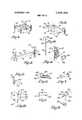
- FIG. 1is a perspective view of a structural selfsupport system made in accordance with the principles of the invention
- FIG. 2is an enlarged perspective view, partially broken away, illustrating the interconnection of typical structural members in the system of FIG. 1;
- FIG. 3is a further enlarged, vertical sectional view adjacent one end of a transverse structural member shown in FIG. 2;
- FIG. 4is a perspective view in exploded form of a tie plate and portions of two structural members which are connected thereby;
- FIG. 5is a perspective view of a portion of the system, showing a spacer structural element used to interconnect two vertical structural members;
- FIG. 6is a perspective view of a portion of the system, showing a tie strap as used to prevent the twisting of shelf-supporting structural members;
- FIG. 7is an enlarged, fragmentary, cross-sectional view of the end of the tie strap taken along the line 7-7 of FIG. 6;
- FIG. 8is a perspective view of a portion of the system, showing a shelf-supporting member
- FIG. 9is an enlarged, fragmentary sectional view of one end of the shelf-supporting member taken along the line 99 of FIG. 8;
- FIG. 10is an exploded perspective view of a portion of the system, showing an alternative self support assembly
- FIG. 11is a fragmentary, vertical, sectional view of a support member used in the system to support decking or flooring between shelve sections, taken along the line l1l1 of FIG. 1;
- FIG. 12is a perspective view of a cleat used to add structural members to the system
- FIG. 13is a fragmentary, perspective view of the cleat of FIG. 12, shown interconnecting two support members;
- FIG. 14is a perspective view of a divider rod used to provide partitions of the system.
- FIG. 1there is shown a structural self-supporting system made in accordance with the principles of the invention. While the embodiment of FIG. 1 illustrates a typical system which can be assembled utilizing the components of the invention, it should be understood, of course, that similar systems or arrangements could be utilized as well.
- the systemcomprises a plurality of uprights 12 with four uprights defining a generally box-like cross-sectional area.
- the uprights 12are of L-shaped cross-sectional configuration and comprise a reduced width section 14 and an enlarged width section 16 shown in greater detail in FIG. 2.
- the sections 14 and 16are integrally formed of steel arranged to define the L-shaped cross-section.
- Centrally formed along the axis of the section 14is a plurality of openings 18, each containing an enlarged central portion 22 of generally circular configuration and reduced width portions 24 and 26 extending in opposite directions from the central portion 22 along the longitudinal axis of the section 14.
- the enlarged width section 16contains a pair of rows of openings 28 and 32 offset from each other and also arranged along the longitudinal axis of the sections 16.
- the openings 28 and 32are generally identical to the openings 18 with the openings 28 of one ofthe rows being staggered with respect to the openings 32.
- supports 42are utilized (FIG. 2).
- the supports 42are generally L- shaped in cross-section and contain a reduced width section 44 and an enlarged width section 46 integral therewith.
- Each of the supports 42is utilized to interconnect two of the uprights 12 near the ends as well as at periodically spaced points, as illustrated in FIG. 1.
- a pair of rivets 48is fastened in spaced-apart relationship in the enlarged section 46, in a plane perpendicular to the longitudinal axis of the enlarged section 46. As shown in FIG.
- the rivetscontain an enlarged head portion 52 which is spaced from the surface of the section 46 by means of a reduced width interconnecting portion 54 which terminates at the surface of the section 46.
- the head portion 52is of a diameter that it can be inserted through the central portion 22 of each of the openings 18, 28
- the supports 42can be connected to the uprights 12 by inserting the rivets 48 into a pair of openings 18, 28 or 32. It should be noted that the center-to-center distance of each pair of rivets 48 is equal to the center-to-center distance of adjacent openings 18, 28 or 32.
- the rows of openings 28 and 32 in section 16are staggered so that the center of one of the openings 28 is positioned midway between the centers of two adjacent openings 32.
- the centers of the openings 18 in section 16are positioned in the same horizontal plane as the centers of the openings 32.
- the supportswill be in the same plane and can be used to support a level shelf.
- a second row of openingscould be provided in the section 14 whose openings are aligned with the row of openings 28, thus giving additional flexibility in adjusting height of shelves.
- openings 28which are offset from the openings 18 and 32 can be utilized with a structural member which is level with the member secured in openings 18 and 32 when the structural member is inserted with its rivets in the openings 28.
- tie plates 62are utilized to interconnect adjacent uprights 12 such as shown in FIG. 1, and form a plurality of box-like structures ad- 7 jacent each other.
- each tie plate 62contains four rivets 48 of similar construction as the rivets in the supports 42. The four rivets are formed so that the vertically arranged rivets are spaced a distance equal to adjacent openings 18 in section 14, whereas the horizontally spaced rivets are spaced a distance equal to the distance between the openings 18 in adjacent sections 14 of the adjacent uprights 12.
- the tie platecan be inserted with the rivets in the openings 18 and then moved downwardly as previously described so as to interlock adjacent uprights.
- aisle tie bars 74are utilized.
- the aisle tie barsare of generally L-shaped cross-sectional configuration and comprise an enlarged width section 76 integrally formed with a reduced width section 78 in a manner similar to the supports 42.
- end plates 82are formed in a plane perpendicular to the longitudinal axis of the tie bar.
- the end plates 82have a crosssectional area approximately equal to the width of the L-shaped sections 76 and 78, so as to form a structurally integral member therewith.
- a pair of rivets 48are positioned in the end plates in a manner as previously described, so as to enable the aisle tie bar 74 to be secured to openings 18 in the uprights 12.
- Wall bar supports 83having construction similar to that of the tie bar 74, but are normally not as long. and are illustrated in FIG. 1 for positioning an upright 12 with respect to a wall 84.
- One end of the wall support 83is secured to a plate 85 mounted on the wall with openings therein for insertion of rivets 48 formed on an end plate 86 of the support 83.
- the rivets on the other end plate of the support 83are positioned in the openings formed in an adjacent upright 12.
- the end plate 86could be secured to the wall by use of expansion bolts or similar devices which can be positioned in openings formed in the end plates.
- the wall support 83is of shorter length than the tie bar 74, yet the construction thereof is similar. It should be understood, of course, that the length of the wall support 83 could vary depending upon the distance between the support structure and the wall to which it is to be secured.
- a tie strap 92which is used to increase the weight capacity of the supports 42 and prevent the supports from rotating.
- the tie strap 92is snapped onto opposite side supports 42.
- the tie strapcomprises a central member 94 which extends between the enlarged width sections 46 of each of the supports 42.
- the ends of the tie straps 92are integrally formed with an L-shaped section at each end.
- the L-shaped sectionsare defined by an end portion 96 and an intermediate portion 98, which connects the ends of the tie strap 92 to the end portion 96.
- the end portion 96 and the intermediate portion 98are positioned adjacent the outer surfaces of the reduced width section 44 and enlarged width section 46, respectively.
- More than one tie strap 92can be used between opposite side supports when the weight capacity to be held by the supports is significant.
- a support channel 104can be utilized.
- the support channel 104is shown in greater detail in FIGS. 8 and 9 and comprises a generally U-shaped crosssectional member having a pair of side walls 106 and a top wall 108.
- the support channelextends between opposite side supports 42 in a manner similar to that of the tie straps 92.
- the junction of the side walls 106 and the top wall 108contain slots 110, enabling the support channel to be fitted so that the top wall 108 is positioned above the reduced width section 44 of the support 42, whereas the ends of the side walls 106 abut the inner surface of the enlarged width section 46 of the supports 42. Then, when a plywood member, such as theplywood member 102, is positioned on the top surface of the reduced width sections .44 of the supports 42,.the
- support channelsare utilized in combination with the supports to reinforce the plywood member and any load which may be stored thereon.
- steel shelving 112which is typically galvini'z'ed metal, can be utilized with thesystem.
- the steel shelving 112can be used to store materials as conventional shelving as illustrated at the top right-hand corner of FIG. 1, or can be used as a raised gangway as illustrated in the bottom left-hand corner of FIG. 1.
- the steel shelving 112is formed of a top surface 114 having L-shaped legs formed of side walls 116 and bottom walls 118.
- the side wall 116is integral with the top surface 114 along its edge and the bottom wall 118 is integral with the side wall 116 and 124 is higher than the side wall 128, and extends a short distance beyond the bottom wall 126 and the side wall 128 at each end of the channelQ
- the extended ends of v the wall 124contains standard system rivets 48, one of which is mounted at the end of the wall 124 and the other one of which is mounted on a downwardly extending leg 132.
- the modified support 122is utilized to position the bottom wall 118 in the channel formed by the walls 124, 126 and 128, with the side wall 116 abuttin the inner surface of the side wall 124.
- the steel shelving 11-2When used as a raised gangway or decking as illustrated in the bottom left-hand corner of FIG. 1 and in FIG. 11, the steel shelving 11-2 is positioned in angled support members 142 which are formed of a bottom wall 144, one end of which is integral with a side wall 146. The other end of the side wall 146 is integrally connected to an angled top wall 148 which extends from the upper end of the side wall 146 towards the bottom'wall 144.
- a pair of conventional system rivets 48is positioned on the side wall 146 adjacent each end enabling the angled support member 142 to be easily mounted on the outer surface of the uprights as is apparent.
- An openingis formed between the free end of the top wall 148 and the bottom wall 144.
- the galvinized steel shelves 112are positioned with their ends inserted into the opening formed between the free end of the top wall 148 and the bottom wall 144 on opposite shelving sections.
- conventional steps 152can be utilized to enable a person to reach the raised gangway.
- FIGS. 12 and 13there is shown a cleat 162 which can be positioned on an upright 12 so as to enable a support 42 or similar type system structure to be secured thereto, as differentiated from tying together similar structures with the plates 62, previou'sly described.
- the cleatcontains a first side plate 164 having a pair of system rivets 48 secured thereto in vertical position.
- a second plate 166Positioned at a degree angle with respect to the plate 164 is a second plate 166 having an enlarged portion opening 168 and a reduced portion opening 172 integral therewith and extending directly below.
- a second enlarged opening 174a portion of which opens into the top surface of the cleat 162, and a reduced portion opening 176 opening into the bottom surface of the enlarged opening 174 is illustrated.
- System rivets 48positioned at the ends of the supports 42, such as that shown in FIG. 3, can be positioned in the plate enabling the support 42 to be secured thereto, as is illustrated in FIG. 12.
- the plate 166can be positioned so that it extends in an opposite direction as shown, so that a support can be positioned thereon in a reverse direction.
- adjustable divider rods 182illustrated on the top left-hand corner of FIG. 1 and in FIG. 14 can be utilized.
- the rodsare formed with a U- shaped top portion 184, one end of which forms an extension 186 in a plane parallel to the uprights 12 and through openings 188 in each of the plywood shelves.
- the extension 186contains notches 192 enablingthe length of the extension 186 to be shortened rather easily.
- the free end 194 of the top endis spaced from the extension 186 so that it can fit into an adjacent opening 188.
- the present systemillustrates the flexibility of making various types of shelving arrangements.
- the openings 18, 28 and 32have reduced width portions extending upwardly and downwardly therefrom, enabling the uprights to be used in a reversed position when desired.
- the supports 42have been illustrated in a first position when used with the shelving 112 in the upper right-hand corner-in FIG. 1, and rotated to a second position when used with the tie straps 92 and support channels 104.
- Such examplesare merely illustrative of the unique flexibility of the system.
- the systemis modular in nature, that is, the system can be initially started with a single box-like structure and additional sections added thereto, when needed.
- a structural self-supporting systemcomprising:
- each of said upright membershaving an L-shaped crosssectional configuration defining a first section, and a second section formed in a plane generally pcrpendicular to said first section;
- each of said openingscomprising an enlarged central portion and a reduced portion contiguous therewith;
- means for interconnecting said uprights and completing said box-like structureincluding elongated support members each having a surface parallel to one of said upright sections and an axis generally perpendicular to the axis of said openings;
- At least one headed projectionextending from said surface adjacent each end of a support member, insertion of said headed projections on one of said support members into openings of spaced-apart upright members providing a rigid interconnection between the support member and said upright members;
- said interconnecting meansincluding a plurality of generally horizontally-positioned, parallel pairs of said support members completing said box-like structure;
- strengthening meansinterconnecting a parallel pair of support members for preventing said support members from rotating, including a tie strap whose central portion extends between said parallel support members with an L-shaped section at each end positioned around one of said parallel support members in rotation preventing engagement therewith.
- a structural self-supporting systemcomprising:
- each of said upright membershaving an L-shaped cross sectional configuration defining a first section, and a second section formed in a plane generally perpendicular to said first section;
- each of said openingscomprising an enlarged central portion and a reduced portion contiguous therewith;
- means for interconnecting said uprights and completing said box-like structureincluding elongated support members each having a surface parallel to one of said upright sections and an axis generally perpendicular to the axis of said openings;
- At least one headed projectionextending from said surface adjacent each end of a support member, insertion of said headed projections on one of said support members into openings of spaced-apart upright members providing a rigid interconnection between the support member and said upright members;
- said interconnecting meansincluding a plurality of generally horizontally-positioned, parallel pairs of e said support members completing said box-like structure;
- strengthening meansinterconnecting a parallel pair of support members for increasing the weight ca pacity of said supports and comprising a channel member of U-shaped cross-sectional configuration with a bottom wall and spaced side walls, said channel member being slotted at its ends along the junction of the bottom wall with the side walls, enabling the ends of said channel member to receive v said support members in holding engagement.
- a structural self-supporting systemcomprising:'
- each of said upright membershaving an L-shaped cross-sectional configuration defining a first seca row of spaced openings in each section extending axially thereof, each of said openings comprising an enlarged central portion and a reduced portion contiguous therewith;
- means for interconnecting said uprights and completing said first box-like structureincluding elongated support members each having a surface parallel to one of said upright sections and an axis generally perpendicular to the axis of said openings;
- At least one headed projectionextending from said surface adjacent each end of a support member, insertion of said headed projections on one of said support members into openings of spaced-apart upright members providing a rigid interconnection between the support member and said upright members;
- a second like, box-like structurejoined to said first box-like structure with the adjacent uprights of each box-like structure being joined together in abutting relationships by means of a tie plate, said tie plate having a plurality of pairs of headed projections formed therein, one pair of headed projections being positioned in each of said adjacent upright members.
- a structural self-supporting systemcomprising:
- each of said upright membershaving an L-shaped crosssectional configuration defining a first section, and a second section formedin a plane generally perpendicular to said first section;
- each of said openingscomprising an enlarged central portion and a reduced portion contiguous therewith;
- means for interconnecting said uprights and completing said box-like structureincluding elongated support members each having a surface parallel to one of said upright sections and an axis generally perpendicular to the axis of said openings;
- At least one headed projectionextending from said surface adjacent each end of a support member, insertion of said headed projections on one of said support members into openings of spaced-apart up right members providing a rigid interconnection between the support member and said upright members;
- a structural self-supporting systemcomprising:
- each of said upright membershaving an L-shaped crosssectional configuration defining a first section, and a second section formed in a plane generally perpendicular to said first section;
- each of said openingscomprising an enlarged central portion and a reduced portion contiguous therewith;
- means for interconnecting said uprights and completing said box-like structureincluding elongated support members each having a surface parallel to one of said upright sections and an axis generally perpendicular to the axis of said openings;
- At least one headed projectionextending from said surface adjacent each end of a support member, insertion of said headed projections on one of said support members into openings of spaced-apart upright members providing a rigid interconnection between the support member and said upright members;
- a set of angled support memberseach having an opening for positioning one edge of a shelf therein, said angled support member containing a side wall havingheaded projections thereon securing said angled support member to two of said uprights, a bottom wall integral with the bottom edge of said side wall and extending generally perpendicular therefrom, and an angled wall extending from the top edge of said side wall toward said bottom wall and being spaced therefrom to define said opening.
- a structural self-supporting systemcomprising:
- each of said upright membershaving an L-shaped crosssectional configuration defining a first section, and a'second section formed in a plane generally perpendicular to said first section;
- each of said openingscomprising an enlarged central portion and a reduced portion contiguous therewith;
- elongated support memberseach having a surface parallel to one of said upright sections and an axis generally perpendicular to the axis of said openings;
- At least one headed projectionextending from said surface adjacent each end of a support member, insertion of said headed projections on one of said support members into openings of spaced-apart upright members providing a rigid interconnection between the support member and said upright members;
- one set of said support membersbeing of generally U-shaped cross-sectional configuration whereby shelving members having side edges of L-shaped configuration can be positioned on said support members, the L-shaped edges of said shelving members nesting in said U-shaped portion of said support members.
- a structural self-supporting systemcomprising:
- a plurality of axially-extending upright membersaran enlarged central portion and a reduced portion contiguous therewith; means for interconnecting said uprights and completing said box-like structure, including elongated support members each having a surface parallel to one of said upright sections and an axis generally perpendicular to the axis of said openings; at least one headed projection extending from said surface adjacent each end of a support member, insertion of said headed projections on one of said support members into openings of spaced-apart upright members providing a rigid interconnection between the support member and said upright members; and at least one cleat member of L-shaped cross-sectional configuration having intersecting side walls and which is secured to one section of an upright member by headed projections positioned on one wall of said cleat, the other wall of said cleat having openings for insertion of headed projections of another support member therein.
- a structural self-supporting systemcomprising:
- each of said upright membershaving an L-shaped crosssectional configuration defining a first section, and a second section formed in a plane generally perpendicular to said first section;
- each of said openingscomprising an enlarged central portion and a reduced portion contiguous therewith;
- means for interconnecting said uprights and completing said box-like structureincluding elongated support members each having a surface parallel to one of said upright sections and an axis generally perpendicular to the axis of said openings;
- At least one headed projectionextending from said surface adjacent each end of a support member, insertion of said headed projections on one of said support members into openings of spaced-apart upright members providing a rigid interconnection between the support member and said upright members;
- a wall barfixedly spacing the box-like structure from a support surface, said wall bar having a generally L-shaped crosssectional configuration with inturned end plates at each end thereof substantially perpendicular to the axis of said bar, one of said end plates having a pair of headed projections positioned in the openings formed in one of said uprights, and the other end plate being secured to said support surface.
- a structural self-supporting systemcomprising:
- each of said upright membershaving an L-shaped cross-sectional configuration defining a first section, and a second section formed in a plane generally perpendicular to said first section;
- - 11a row of spaced openings in each section extending axially thereof, each of said openings comprising an enlarged central portion and a reduced portion contiguous therewith;
- means for interconnecting said uprights and completing said box-like structureincluding elongated support members each having a surface parallel to one of said upright sections and an axis generally perpendicular to the axis of said openings; at least one headed projection extending from said surface adjacent each end of a support member,
- a structural self-supporting systemcomprising:
- each of said upright membershaving an L-shaped crosssectional configuration defining a first section and a second section formed in a plane generally perpendicular to said first section;
- each of said openingscomprising an enlarged central portionand a reduced portion contiguous therewith;
- elongated support memberseach having a surface parallel to one of said upright sections and an axis generally perpendicular to the axis of said openings;
- At least one headed projectionextending from said surface adjacent each end of a support member, insertion of said headed projections on one of said support members into openings of spaced-apart upright members providing a rigid interconnection between the support member and said upright members;
- a plurality of vertically spaced shelvespositioned on said support members in planes generally perpendicular to said upright members, said shelves having openings extending therethrough, and dividers positioned in said openings to form a shelf divider system, said dividers being formed of rods extending through said openings in a plane generally parallel to said uprights, and one end of said rods having a curved portion for securing said rods to one of said shelves.
Landscapes
- Engineering & Computer Science (AREA)
- General Engineering & Computer Science (AREA)
- Mechanical Engineering (AREA)
- Assembled Shelves (AREA)
Abstract
Description
Claims (11)
Priority Applications (1)
| Application Number | Priority Date | Filing Date | Title |
|---|---|---|---|
| US00304188AUS3846944A (en) | 1970-12-21 | 1972-11-06 | Structural self-supporting system |
Applications Claiming Priority (2)
| Application Number | Priority Date | Filing Date | Title |
|---|---|---|---|
| US10032170A | 1970-12-21 | 1970-12-21 | |
| US00304188AUS3846944A (en) | 1970-12-21 | 1972-11-06 | Structural self-supporting system |
Publications (1)
| Publication Number | Publication Date |
|---|---|
| US3846944Atrue US3846944A (en) | 1974-11-12 |
Family
ID=26797036
Family Applications (1)
| Application Number | Title | Priority Date | Filing Date |
|---|---|---|---|
| US00304188AExpired - LifetimeUS3846944A (en) | 1970-12-21 | 1972-11-06 | Structural self-supporting system |
Country Status (1)
| Country | Link |
|---|---|
| US (1) | US3846944A (en) |
Cited By (49)
| Publication number | Priority date | Publication date | Assignee | Title |
|---|---|---|---|---|
| US3976014A (en)* | 1975-03-03 | 1976-08-24 | Brown Clifford S | Modular shelving apparatus |
| US3986318A (en)* | 1974-09-30 | 1976-10-19 | Interlake, Inc. | Structural member and assembly thereof |
| US4048059A (en)* | 1975-11-24 | 1977-09-13 | Aurora Equipment Company | Pallet rack and decking combination |
| US4106630A (en)* | 1977-04-28 | 1978-08-15 | Parsteel Products Company, Inc. | Storage rack assembly |
| US4224776A (en)* | 1978-02-01 | 1980-09-30 | Easy Up Shelving, Inc. | Mezzanine support beam for multi-story hook-in type shelving |
| US4514950A (en)* | 1981-11-27 | 1985-05-07 | Goodson Jr Albert A | Building framing system and method |
| US4549665A (en)* | 1982-09-03 | 1985-10-29 | Republic Steel Corporation | Shelf assembly |
| US4709517A (en)* | 1986-06-02 | 1987-12-01 | Architectural Wall Systems, Inc. | Floor-to-ceiling wall system |
| US4805787A (en)* | 1986-04-11 | 1989-02-21 | National Service Industries | Hanging compartment support system |
| US5496232A (en)* | 1994-10-31 | 1996-03-05 | Morris; Denny W. | Modular playground equipment system |
| US5797502A (en)* | 1996-10-10 | 1998-08-25 | Western Pacific Storage Systems, Inc. | Universal, height-adjustable hanger bracket |
| US6123314A (en)* | 1994-11-30 | 2000-09-26 | Lockheed Martin Corporation | Quick mounting mechanism and method |
| US6726039B2 (en)* | 2001-03-21 | 2004-04-27 | Paul Flum Ideas, Inc. | Inventory control system for walk-in display coolers and the like |
| US20050115164A1 (en)* | 2002-04-18 | 2005-06-02 | Han Bong K. | Construction method for src structured high rise building |
| US20060026907A1 (en)* | 2004-08-04 | 2006-02-09 | Jeremy Gilstrap | Adjustable heavy girder tiedown |
| US20080145197A1 (en)* | 2006-12-15 | 2008-06-19 | Harry Randall Taylor | Roller rack |
| EP1989954A3 (en)* | 2007-05-09 | 2008-12-24 | Element -System Rudolf Bohnacker GmbH | Free standing rack |
| US20090159545A1 (en)* | 2007-12-20 | 2009-06-25 | Jakie Shetler | Storage Rack Decking Derived from a Single Sheet of Sheet Metal |
| EP1987735A3 (en)* | 2007-03-10 | 2009-09-30 | Irega AG | Block shelving for storage, in particular bicycles |
| EP1825790A4 (en)* | 2004-12-14 | 2011-01-12 | Garcia De Alba Luis Felipe Rego | Self-supporting packaging and display unit |
| US20120000871A1 (en)* | 2010-07-02 | 2012-01-05 | Edsal Manufacturing Co., Inc. | Portion of shelf and support for shelving unit |
| US20120006873A1 (en)* | 2010-07-12 | 2012-01-12 | Ferno-Washington, Inc. | Litter support systems for medical care units and methods of their use |
| US20120048818A1 (en)* | 2010-08-26 | 2012-03-01 | Geelong Sales Company International Ltd., | Bin Storage Rack |
| US20120103925A1 (en)* | 2009-07-08 | 2012-05-03 | Keymed (Medical & Industrial Equipment) Ltd. | Shelving System |
| US20130168341A1 (en)* | 2010-12-16 | 2013-07-04 | Huliot Storage Solutions Ltd. | Modular storage system, fasteners and method of assembly |
| US8708169B1 (en)* | 2013-01-31 | 2014-04-29 | Shun-Teng Chen | Combination cabinet |
| US20140284294A1 (en)* | 2013-03-22 | 2014-09-25 | Silverack, Llc | Shelving Support Bracket for a Storage Rack |
| US8992238B2 (en) | 2010-07-12 | 2015-03-31 | Ferno-Washington, Inc. | Mounting system having a mounting plate with mounting studs and electrical contacts |
| US20150090683A1 (en)* | 2013-09-27 | 2015-04-02 | Pro-Mart Industries, Inc. | Storage rack and cross-bar support |
| US20150157144A1 (en)* | 2013-04-08 | 2015-06-11 | Presentoirs One Way Inc. | Modular shelving system |
| US9362610B2 (en) | 2012-02-14 | 2016-06-07 | Ferno-Washington, Inc. | Quick antenna attachment system |
| AU2011201493B2 (en)* | 2010-07-02 | 2016-07-07 | Edsal Manufacturing Company, Inc. | Variable configuration shelving apparatus and methods |
| US9611975B2 (en) | 2013-02-11 | 2017-04-04 | Ferno-Washington, Inc. | Equipment mounting system |
| US20170241139A1 (en)* | 2016-02-19 | 2017-08-24 | Edwin Moyano | Adjustable Dap Assembly |
| US9944217B2 (en) | 2013-02-11 | 2018-04-17 | Ferno-Washington, Inc. | Equipment mounting system |
| US20180279782A1 (en)* | 2017-03-28 | 2018-10-04 | Edsal Manufacturing Company, Inc. | Shelving unit with capacity increasing tie members |
| US10165855B2 (en)* | 2010-05-26 | 2019-01-01 | Seville Classics, Inc. | Storage rack |
| US10307313B2 (en) | 2013-02-11 | 2019-06-04 | Ferno-Washington, Inc. | Equipment mounting system |
| US10398203B2 (en) | 2014-02-11 | 2019-09-03 | Ferno-Washington, Inc. | Crash-ready, portable, compartmentalization device |
| US10398207B2 (en) | 2014-02-11 | 2019-09-03 | Ferno-Washington, Inc. | Crash-ready, portable, compartmentalization device |
| US20200056392A1 (en)* | 2018-08-16 | 2020-02-20 | Distribution Logix, Inc. | Data Center Infrastructure Support System |
| US10736415B1 (en)* | 2019-07-22 | 2020-08-11 | Frazier Industrial Company | Formed support member with tab securing feature |
| US10745198B1 (en)* | 2019-07-22 | 2020-08-18 | Frazier Industrial Company | Formed support member with antirotation feature |
| US10786055B2 (en) | 2014-07-18 | 2020-09-29 | Ferno-Washington, Inc. | Crash-ready, portable, compartmentalization device |
| US11083265B2 (en) | 2014-02-11 | 2021-08-10 | Ferno-Washington, Inc. | Magnetic pouch attachment mechanism with crash stable locking teeth |
| US11246396B2 (en) | 2019-09-03 | 2022-02-15 | Joshua B. Boos | Modular cabinet shelf |
| US11304546B1 (en)* | 2018-02-05 | 2022-04-19 | Joshua B. Boos | Modular cabinet that divides and subdivides product according to its dimensions |
| US11344114B2 (en)* | 2018-03-12 | 2022-05-31 | Hangzhou United Tools Co., Ltd. | Shelf |
| US20240067452A1 (en)* | 2022-08-26 | 2024-02-29 | Richard A. Thurston | Reconfigurable open frame storage system and components thereof |
Citations (9)
| Publication number | Priority date | Publication date | Assignee | Title |
|---|---|---|---|---|
| US701079A (en)* | 1901-12-06 | 1902-05-27 | William C Peckham | Adjustable shelf-bracket. |
| US1288010A (en)* | 1918-07-06 | 1918-12-17 | William Harry Isaac | Shelf-bracket. |
| US1818418A (en)* | 1928-02-04 | 1931-08-11 | Mcclintic Marshall Corp | Steel frame house construction |
| US2746780A (en)* | 1946-06-28 | 1956-05-22 | Dexion Ltd | Rigid angle joint |
| US3048245A (en)* | 1960-02-29 | 1962-08-07 | Arean Eastern Ltd | Locking mechanism |
| US3294250A (en)* | 1964-03-05 | 1966-12-27 | Aurora Equipment Co | Shelving structure |
| US3353507A (en)* | 1966-07-11 | 1967-11-21 | George R Squires | Adjustable shelving |
| US3463325A (en)* | 1967-06-22 | 1969-08-26 | Interlake Steel Corp | Pallet rack beam retainer |
| US3506138A (en)* | 1968-04-03 | 1970-04-14 | Ray Steel Co | Storage rack system |
- 1972
- 1972-11-06USUS00304188Apatent/US3846944A/ennot_activeExpired - Lifetime
Patent Citations (9)
| Publication number | Priority date | Publication date | Assignee | Title |
|---|---|---|---|---|
| US701079A (en)* | 1901-12-06 | 1902-05-27 | William C Peckham | Adjustable shelf-bracket. |
| US1288010A (en)* | 1918-07-06 | 1918-12-17 | William Harry Isaac | Shelf-bracket. |
| US1818418A (en)* | 1928-02-04 | 1931-08-11 | Mcclintic Marshall Corp | Steel frame house construction |
| US2746780A (en)* | 1946-06-28 | 1956-05-22 | Dexion Ltd | Rigid angle joint |
| US3048245A (en)* | 1960-02-29 | 1962-08-07 | Arean Eastern Ltd | Locking mechanism |
| US3294250A (en)* | 1964-03-05 | 1966-12-27 | Aurora Equipment Co | Shelving structure |
| US3353507A (en)* | 1966-07-11 | 1967-11-21 | George R Squires | Adjustable shelving |
| US3463325A (en)* | 1967-06-22 | 1969-08-26 | Interlake Steel Corp | Pallet rack beam retainer |
| US3506138A (en)* | 1968-04-03 | 1970-04-14 | Ray Steel Co | Storage rack system |
Cited By (85)
| Publication number | Priority date | Publication date | Assignee | Title |
|---|---|---|---|---|
| US3986318A (en)* | 1974-09-30 | 1976-10-19 | Interlake, Inc. | Structural member and assembly thereof |
| US3976014A (en)* | 1975-03-03 | 1976-08-24 | Brown Clifford S | Modular shelving apparatus |
| US4048059A (en)* | 1975-11-24 | 1977-09-13 | Aurora Equipment Company | Pallet rack and decking combination |
| US4106630A (en)* | 1977-04-28 | 1978-08-15 | Parsteel Products Company, Inc. | Storage rack assembly |
| US4224776A (en)* | 1978-02-01 | 1980-09-30 | Easy Up Shelving, Inc. | Mezzanine support beam for multi-story hook-in type shelving |
| US4514950A (en)* | 1981-11-27 | 1985-05-07 | Goodson Jr Albert A | Building framing system and method |
| US4549665A (en)* | 1982-09-03 | 1985-10-29 | Republic Steel Corporation | Shelf assembly |
| US4805787A (en)* | 1986-04-11 | 1989-02-21 | National Service Industries | Hanging compartment support system |
| US4709517A (en)* | 1986-06-02 | 1987-12-01 | Architectural Wall Systems, Inc. | Floor-to-ceiling wall system |
| US5496232A (en)* | 1994-10-31 | 1996-03-05 | Morris; Denny W. | Modular playground equipment system |
| US6123314A (en)* | 1994-11-30 | 2000-09-26 | Lockheed Martin Corporation | Quick mounting mechanism and method |
| US5797502A (en)* | 1996-10-10 | 1998-08-25 | Western Pacific Storage Systems, Inc. | Universal, height-adjustable hanger bracket |
| US6726039B2 (en)* | 2001-03-21 | 2004-04-27 | Paul Flum Ideas, Inc. | Inventory control system for walk-in display coolers and the like |
| US20050115164A1 (en)* | 2002-04-18 | 2005-06-02 | Han Bong K. | Construction method for src structured high rise building |
| US7647742B2 (en)* | 2002-04-18 | 2010-01-19 | Bong Kil Han | Construction method for SRC structured high rise building |
| US20060026907A1 (en)* | 2004-08-04 | 2006-02-09 | Jeremy Gilstrap | Adjustable heavy girder tiedown |
| US7891144B2 (en)* | 2004-08-04 | 2011-02-22 | Simpson Strong-Tie Company, I{umlaut over (n)}c. | Adjustable heavy girder tiedown |
| EP1825790A4 (en)* | 2004-12-14 | 2011-01-12 | Garcia De Alba Luis Felipe Rego | Self-supporting packaging and display unit |
| US20080145197A1 (en)* | 2006-12-15 | 2008-06-19 | Harry Randall Taylor | Roller rack |
| EP1987735A3 (en)* | 2007-03-10 | 2009-09-30 | Irega AG | Block shelving for storage, in particular bicycles |
| EP1989954A3 (en)* | 2007-05-09 | 2008-12-24 | Element -System Rudolf Bohnacker GmbH | Free standing rack |
| US7891507B2 (en)* | 2007-12-20 | 2011-02-22 | Jakie Shetler | Storage rack decking derived from a single sheet of sheet metal |
| US20090159545A1 (en)* | 2007-12-20 | 2009-06-25 | Jakie Shetler | Storage Rack Decking Derived from a Single Sheet of Sheet Metal |
| US20120103925A1 (en)* | 2009-07-08 | 2012-05-03 | Keymed (Medical & Industrial Equipment) Ltd. | Shelving System |
| US8561820B2 (en)* | 2009-07-08 | 2013-10-22 | Keymed (Medical & Industrial Equipment) Ltd. | Shelving system |
| US12268299B2 (en)* | 2010-05-26 | 2025-04-08 | Seville Classics Inc. | Storage rack |
| US11564488B2 (en)* | 2010-05-26 | 2023-01-31 | Seville Classics Inc | Storage rack |
| US10485337B2 (en)* | 2010-05-26 | 2019-11-26 | Seville Classics, Inc. | Storage rack |
| US20200085189A1 (en)* | 2010-05-26 | 2020-03-19 | Seville Classics Inc. | Storage Rack |
| US10806252B2 (en)* | 2010-05-26 | 2020-10-20 | Seville Classics Inc. | Storage rack |
| US20220192371A1 (en)* | 2010-05-26 | 2022-06-23 | Seville Classics Inc. | Storage Rack |
| US20230157446A1 (en)* | 2010-05-26 | 2023-05-25 | Seville Classics Inc. | Storage Rack |
| US20250228363A1 (en)* | 2010-05-26 | 2025-07-17 | Seville Classics, Inc. | Storage Rack |
| US11930923B2 (en)* | 2010-05-26 | 2024-03-19 | Seville Classics Inc. | Storage rack |
| US10165855B2 (en)* | 2010-05-26 | 2019-01-01 | Seville Classics, Inc. | Storage rack |
| US20240138564A1 (en)* | 2010-05-26 | 2024-05-02 | Seville Classics Inc. | Storage Rack |
| US9375102B2 (en)* | 2010-07-02 | 2016-06-28 | Edsal Manufacturing Company, Inc. | Portion of shelf and support for shelving unit |
| AU2011201493B2 (en)* | 2010-07-02 | 2016-07-07 | Edsal Manufacturing Company, Inc. | Variable configuration shelving apparatus and methods |
| US20120000871A1 (en)* | 2010-07-02 | 2012-01-05 | Edsal Manufacturing Co., Inc. | Portion of shelf and support for shelving unit |
| US8992238B2 (en) | 2010-07-12 | 2015-03-31 | Ferno-Washington, Inc. | Mounting system having a mounting plate with mounting studs and electrical contacts |
| US8636154B2 (en)* | 2010-07-12 | 2014-01-28 | Ferno-Washington, Inc. | Litter support systems for medical care units and methods of their use |
| US20120006873A1 (en)* | 2010-07-12 | 2012-01-12 | Ferno-Washington, Inc. | Litter support systems for medical care units and methods of their use |
| US20120048818A1 (en)* | 2010-08-26 | 2012-03-01 | Geelong Sales Company International Ltd., | Bin Storage Rack |
| US8714372B2 (en)* | 2010-12-16 | 2014-05-06 | Huliot Storage Solutions Ltd. | Kit for assembling a rigid support structure |
| US20130168341A1 (en)* | 2010-12-16 | 2013-07-04 | Huliot Storage Solutions Ltd. | Modular storage system, fasteners and method of assembly |
| US9362610B2 (en) | 2012-02-14 | 2016-06-07 | Ferno-Washington, Inc. | Quick antenna attachment system |
| US8708169B1 (en)* | 2013-01-31 | 2014-04-29 | Shun-Teng Chen | Combination cabinet |
| US9692194B2 (en) | 2013-02-11 | 2017-06-27 | Ferno-Washington, Inc. | Track having a backing plate with a plurality of slots with a plurality of open regions |
| US9611975B2 (en) | 2013-02-11 | 2017-04-04 | Ferno-Washington, Inc. | Equipment mounting system |
| US10170880B2 (en) | 2013-02-11 | 2019-01-01 | Ferno-Washington, Inc. | Mount having a mounting plate with mounting studs and electrical contacts |
| US9379504B2 (en) | 2013-02-11 | 2016-06-28 | Ferno-Washington, Inc. | Track having a backing plate with a plurality of slots and electrical contacts adjacent to each other |
| USD835499S1 (en) | 2013-02-11 | 2018-12-11 | Ferno-Washington, Inc. | Equipment mounting plate |
| US11066004B2 (en) | 2013-02-11 | 2021-07-20 | Ferno-Washington, Inc. | Equipment mounting system |
| US10307313B2 (en) | 2013-02-11 | 2019-06-04 | Ferno-Washington, Inc. | Equipment mounting system |
| USD905544S1 (en) | 2013-02-11 | 2020-12-22 | Ferno-Washington, Inc. | Equipment mounting plate |
| US9944217B2 (en) | 2013-02-11 | 2018-04-17 | Ferno-Washington, Inc. | Equipment mounting system |
| US10072788B2 (en) | 2013-02-11 | 2018-09-11 | Ferno-Washington, Inc. | Equipment mounting system |
| USD868569S1 (en) | 2013-02-11 | 2019-12-03 | Ferno-Washington, Inc. | Equipment mounting plate |
| US10544895B2 (en) | 2013-02-11 | 2020-01-28 | Ferno-Washington, Inc. | Equipment mounting system |
| US20140284294A1 (en)* | 2013-03-22 | 2014-09-25 | Silverack, Llc | Shelving Support Bracket for a Storage Rack |
| US20150157144A1 (en)* | 2013-04-08 | 2015-06-11 | Presentoirs One Way Inc. | Modular shelving system |
| US9204737B2 (en)* | 2013-04-08 | 2015-12-08 | Presentoirs One Way Inc. | Modular shelving system |
| US9386855B2 (en)* | 2013-09-27 | 2016-07-12 | Pro-Mart Industries, Inc. | Storage rack and cross-bar support |
| US20150090683A1 (en)* | 2013-09-27 | 2015-04-02 | Pro-Mart Industries, Inc. | Storage rack and cross-bar support |
| US10398203B2 (en) | 2014-02-11 | 2019-09-03 | Ferno-Washington, Inc. | Crash-ready, portable, compartmentalization device |
| US11083265B2 (en) | 2014-02-11 | 2021-08-10 | Ferno-Washington, Inc. | Magnetic pouch attachment mechanism with crash stable locking teeth |
| US10912360B2 (en) | 2014-02-11 | 2021-02-09 | Ferno-Washington, Inc. | Magnetic pouch attachment mechanism with crash stable locking teeth |
| US10398207B2 (en) | 2014-02-11 | 2019-09-03 | Ferno-Washington, Inc. | Crash-ready, portable, compartmentalization device |
| US10786055B2 (en) | 2014-07-18 | 2020-09-29 | Ferno-Washington, Inc. | Crash-ready, portable, compartmentalization device |
| US11490700B2 (en) | 2014-07-18 | 2022-11-08 | Ferno-Washington, Inc. | Crash-ready, portable, compartmentalization device |
| US10280619B2 (en)* | 2016-02-19 | 2019-05-07 | Edwin Moyano | Adjustable dap assembly |
| US20170241139A1 (en)* | 2016-02-19 | 2017-08-24 | Edwin Moyano | Adjustable Dap Assembly |
| US20180279782A1 (en)* | 2017-03-28 | 2018-10-04 | Edsal Manufacturing Company, Inc. | Shelving unit with capacity increasing tie members |
| US10299594B2 (en)* | 2017-03-28 | 2019-05-28 | Edsal Manufacturing Company, Inc. | Shelving unit with capacity increasing tie members |
| US11304546B1 (en)* | 2018-02-05 | 2022-04-19 | Joshua B. Boos | Modular cabinet that divides and subdivides product according to its dimensions |
| US11344114B2 (en)* | 2018-03-12 | 2022-05-31 | Hangzhou United Tools Co., Ltd. | Shelf |
| US10968652B2 (en)* | 2018-08-16 | 2021-04-06 | Jonathan Harinck | Data center infrastructure support system |
| US20200056392A1 (en)* | 2018-08-16 | 2020-02-20 | Distribution Logix, Inc. | Data Center Infrastructure Support System |
| US10947040B2 (en)* | 2019-07-22 | 2021-03-16 | Frazier Industrial Company | Formed support member |
| US10745198B1 (en)* | 2019-07-22 | 2020-08-18 | Frazier Industrial Company | Formed support member with antirotation feature |
| US10736415B1 (en)* | 2019-07-22 | 2020-08-11 | Frazier Industrial Company | Formed support member with tab securing feature |
| US10945521B2 (en)* | 2019-07-22 | 2021-03-16 | Frazier Industrial Company | Formed support member |
| US11246396B2 (en) | 2019-09-03 | 2022-02-15 | Joshua B. Boos | Modular cabinet shelf |
| US20240067452A1 (en)* | 2022-08-26 | 2024-02-29 | Richard A. Thurston | Reconfigurable open frame storage system and components thereof |
| US12168574B2 (en)* | 2022-08-26 | 2024-12-17 | Richard A. Thurston | Reconfigurable open frame storage system and components thereof |
Similar Documents
| Publication | Publication Date | Title |
|---|---|---|
| US3846944A (en) | Structural self-supporting system | |
| US3212648A (en) | Cantilever rack | |
| US3465895A (en) | Storage rack | |
| US4342397A (en) | Fastenings for storage racks | |
| US2654487A (en) | Storage rack | |
| US3195735A (en) | Detachable structure and joint therefor | |
| US3070237A (en) | Pallet rack | |
| US3527359A (en) | Tray rack cabinet with removable guides | |
| USRE25117E (en) | edwards | |
| US3102641A (en) | Storage rack | |
| US3339750A (en) | Structural connector | |
| US4173934A (en) | Shelving structure | |
| US3217894A (en) | Locking mechanism | |
| US3391795A (en) | Drive-in pallet rack | |
| US3144944A (en) | Drive-in pallet rack | |
| US3438343A (en) | Stacking frames for pallets | |
| USRE24535E (en) | - shelving unit | |
| US3536016A (en) | Shelf structure | |
| US3268089A (en) | Deck section for storage rack | |
| US4053246A (en) | Storage rack assembly and mounting clamp therefor | |
| US3885675A (en) | Construction kit for the erection of storage and display structures of varying dimensions in the form of shelves, cupboards, display cases and the like | |
| GB1585947A (en) | Collapsible shelf | |
| US4503781A (en) | Prefabricated shelf unit | |
| US3978631A (en) | Display units with socket-mounted standards | |
| US3106297A (en) | Pallet rack |
Legal Events
| Date | Code | Title | Description |
|---|---|---|---|
| AS | Assignment | Owner name:BUCKHORN METAL PRODUCTS INC. Free format text:CHANGE OF NAME;ASSIGNOR:NEW IDRIA, INC.;REEL/FRAME:004483/0337 Effective date:19830630 | |
| AS | Assignment | Owner name:WESTERN PACIFIC STORAGE SYSTEMS, 1532 SOUTH CALIFO Free format text:ASSIGNMENT OF ASSIGNORS INTEREST.;ASSIGNOR:BUCKHORN METAL PRODUCTS INC.;REEL/FRAME:004492/0011 Effective date:19851211 | |
| STCF | Information on status: patent grant | Free format text:PATENTED FILE - (OLD CASE ADDED FOR FILE TRACKING PURPOSES) | |
| AS | Assignment | Owner name:NEW IDRIA INC. Free format text:MERGER;ASSIGNOR:BARTON-KING SYSTEMS CORPORATION (MERGED INTO);REEL/FRAME:004614/0556 Effective date:19770622 | |
| AS | Assignment | Owner name:RAPID RACK INDUSTRIES, INC., 747 EAST GREEN ST., P Free format text:ASSIGNMENT OF ASSIGNORS INTEREST.;ASSIGNOR:LAMBERT, HARRY;REEL/FRAME:004729/0241 Effective date:19870622 Owner name:RAPID RACK INDUSTRIES, INC., A CORP. OF CA,CALIFOR Free format text:ASSIGNMENT OF ASSIGNORS INTEREST;ASSIGNOR:LAMBERT, HARRY;REEL/FRAME:004729/0241 Effective date:19870622 | |
| AS | Assignment | Owner name:WESTERN PACIFIC STORAGE SYSTEMS, A CORP. OF CA, CA Free format text:ASSIGNMENT OF ASSIGNORS INTEREST.;ASSIGNOR:BUCKHORN METAL PRODUCTS INC.;REEL/FRAME:005032/0586 Effective date:19881201 | |
| AS | Assignment | Owner name:PATRIARCH PARTNERS AGENCY SERVICES, LLC, AS ADMINI Free format text:SECURITY AGREEMENT;ASSIGNOR:RAPID ROCK INDUSTRIES, INC.;REEL/FRAME:031353/0698 Effective date:20131004 Owner name:PATRIARCH PARTNERS AGENCY SERVICES, LLC, AS ADMINI Free format text:SECURITY AGREEMENT;ASSIGNOR:RAPID RACK INDUSTRIES, INC.;REEL/FRAME:031353/0706 Effective date:20131004 | |
| AS | Assignment | Owner name:PATRIARCH PARTNERS AGENCY SERVICES, LLC, AS ADMINI Free format text:CORRECTIVE ASSIGNMENT TO CORRECT THE NAME OF THE CONVEYING PARTY PREVIOUSLY RECORDED ON REEL 031353 FRAME 0698. ASSIGNOR(S) HEREBY CONFIRMS THE SECURITY AGREEMENT;ASSIGNOR:RAPID RACK INDUSTRIES, INC.;REEL/FRAME:031380/0380 Effective date:20131004 | |
| AS | Assignment | Owner name:PATRIARCH PARTNERS AGENCY SERVICES, LLC, NEW YORK Free format text:ASSIGNMENT OF ASSIGNORS INTEREST;ASSIGNOR:RAPID RACK INDUSTRIES, INC.;REEL/FRAME:031590/0657 Effective date:20131022 Owner name:SILVERACK, LLC, CALIFORNIA Free format text:ASSIGNMENT OF ASSIGNORS INTEREST;ASSIGNOR:PATRIARCH PARTNERS AGENCY SERVICES, LLC;REEL/FRAME:031590/0786 Effective date:20131022 Owner name:PATRIARCH PARTNERS AGENCY SERVICES, LLC, NEW YORK Free format text:SECURITY AGREEMENT;ASSIGNOR:SILVERACK, LLC;REEL/FRAME:031627/0347 Effective date:20131022 |