US3844302A - Collapsible umbrella - Google Patents
Collapsible umbrellaDownload PDFInfo
- Publication number
- US3844302A US3844302AUS00234719AUS23471972AUS3844302AUS 3844302 AUS3844302 AUS 3844302AUS 00234719 AUS00234719 AUS 00234719AUS 23471972 AUS23471972 AUS 23471972AUS 3844302 AUS3844302 AUS 3844302A
- Authority
- US
- United States
- Prior art keywords
- cover
- ribs
- umbrella
- fingers
- notch
- Prior art date
- Legal status (The legal status is an assumption and is not a legal conclusion. Google has not performed a legal analysis and makes no representation as to the accuracy of the status listed.)
- Expired - Lifetime
Links
- 239000002991molded plasticSubstances0.000claimsdescription2
- 239000004033plasticSubstances0.000claimsdescription2
- 229920003023plasticPolymers0.000claimsdescription2
- 238000007493shaping processMethods0.000abstractdescription7
- 239000002952polymeric resinSubstances0.000abstractdescription5
- 229920003002synthetic resinPolymers0.000abstractdescription5
- 230000008602contractionEffects0.000description7
- 210000005069earsAnatomy0.000description7
- 230000002093peripheral effectEffects0.000description6
- 238000003780insertionMethods0.000description3
- 230000037431insertionEffects0.000description3
- 235000001674Agaricus brunnescensNutrition0.000description2
- 238000010276constructionMethods0.000description2
- 230000013011matingEffects0.000description2
- -1polypropylenePolymers0.000description2
- 229920005989resinPolymers0.000description2
- 239000011347resinSubstances0.000description2
- 239000004698PolyethyleneSubstances0.000description1
- 239000004743PolypropyleneSubstances0.000description1
- 230000004075alterationEffects0.000description1
- VTTONGPRPXSUTJ-UHFFFAOYSA-NbufoteninChemical compoundC1=C(O)C=C2C(CCN(C)C)=CNC2=C1VTTONGPRPXSUTJ-UHFFFAOYSA-N0.000description1
- 239000003795chemical substances by applicationSubstances0.000description1
- 230000006835compressionEffects0.000description1
- 238000007906compressionMethods0.000description1
- 230000000694effectsEffects0.000description1
- 239000004744fabricSubstances0.000description1
- 238000002347injectionMethods0.000description1
- 239000007924injectionSubstances0.000description1
- 238000001746injection mouldingMethods0.000description1
- 239000000463materialSubstances0.000description1
- 238000000465mouldingMethods0.000description1
- 229920000573polyethylenePolymers0.000description1
- 229920001155polypropylenePolymers0.000description1
Images


Classifications
- A—HUMAN NECESSITIES
- A45—HAND OR TRAVELLING ARTICLES
- A45B—WALKING STICKS; UMBRELLAS; LADIES' OR LIKE FANS
- A45B19/00—Special folding or telescoping of umbrellas
- A45B19/06—Special folding or telescoping of umbrellas with telescopic ribs
Definitions
- a collapsible umbrellaof the type including framedefining two section ribs in which the outer rib sections are slideable along the inner rib sections between extended and contracted positions and a cover overlying the frame and secured to the umbrella notch and the inner and outer ends of the outer ribs, is provided with a spreader member including a hub mounted on the notch and outwardly sprung radially projecting resilient fingers underlying the crown of the cover.
- the hub and fingersare integrally formed of a synthetic polymeric resin and the fingers are interconnected by pliable flexible connectors which may be integrally formed with the fingers and are positioned between the unbrella ribs and cover, the fingers interdigitating the ribs.
- the present inventionrelates generally to improvements in umbrellas and it relates particularly to an improved collapsible umbrella provided with a mechanism facilitating the compact shaping of the umbrella cover attendant to the collapsing of the umbrella.
- Collapsible umbrellasgenerally include a shaft with telescoping sections permitting longitudinal extension and contraction thereof and ribs which are likewise formed of two sections relatively movable between longitudinally extended and contracted positions.
- rib outer sectionsare slideable along the rib inner, notch-pivoted sections and are hinged at their inner ends to spreaders which are connected to the runner.
- the umbrella coveris mounted at its center to the notch and is connected at points along its periphery and between its center and periphery respectively to the outer and inner ends of the outer rib sections.
- the collapsible umbrella of the above typepossesses an important drawback and disadvantage.
- the inner section of the umbrella coverWith the collapse of the closed umbrella frame the inner section of the umbrella cover is generally bunched into a bulky condition and must be manually reformed and compacted to permit the insertion of the collapsed umbrella into a mating sheath or envelope.
- This umbrella cover shaping operationis, at its best, awkward, inconvenient and time consuming, requiring a high degree of manual dexterity for optimum results and otherwise leaving much to be desired.
- Another object of the present inventionis to provide an improved collapsible umbrella.
- Still another object of the present inventionis to provide an improved collapsible umbrella of type provided with longitudinally contractable two piece ribs.
- a further object of the present inventionis to provide an improved collapsible umbrella provided with means for shaping the umbrella cover attendant the collapse of the umbrella to facilitate the application of a cover sheath thereover.
- Still a further object of the presentinventionis to provide a collapsible umbrella of the above nature having a cover-shaping mechanism characterized by its simplicity, reliability, ruggedness, convenience, ease of operation and low cost.
- a collapsible umbrellacomprising a shaft, a notch mounted on said shaft, a plurality of longitudinally contractable ribs hinged attheir inner ends to said notch and swingable between an open position extending outwardly from said notch and a closed position extending proximate said shaft, elements slideable along said ribs between positions proximate and remote from said notch with the contraction and extension respectively of said ribs, a cover member overlying said ribs and secured at its outer border to the outer ends of said ribs and at points between the center and periphery of said cover to said slide elements, said cover member including a crown section between the center of said cover and the points thereof secured to said slide elements, and fingers interdigitating the ribs and connected by flexible elements for resiliently outwardly spreading and maintaining said cover crown section when said ribs are in their closed contracted condition.
- the notchincludes a circular base to the border of which the umbrella ribs are hinged and an integrally formed upwardly directed externally threaded hollow cylindrical section mounted on the umbrella shaft.
- the umbrella coverhas a central opening engaged by a grommet which registers with the notch and cylindrical section and is locked in position by a screw cap engaging the threaded cylindrical section.
- the umbrella ribsinclude inner sections and outer sections longitudinally slideable along the respective inner sections, the umbrella cover being secured at its periphery and at inwardly spaced points to the outer ribs inner and outer ends.
- the cover crown spreading meansincludes an annulus or hub sandwiched between the notch base and the cover grommet and resilient fingers projecting radially from the hub and sprung outwardly.
- the resilient fingersmay be loops or sector-shaped elements formed of spring wire, resilient arms formed of synthetic organic ploymeric resins, or the like.
- the resilient fingersmay straddle or interdigitate the ribs and in the latter case are provided with flexible connector elements which may be integrally formed with the fingers and overlie the ribs.
- the resilient fingersWhen the umbrella is closed, the resilient fingers are pressed inwardly by the overlying umbrella cover but upon longitudinal contraction of the ribs the upper or inner part of the cover is released and is spread uniformly outwardly by the resilient fingers and assumes an open dome or mushroom shape.
- the resilient open crownis easily and rapidly collapsed into a compact uniform condition by pressing axially downwardly on the cover crown to collapse the resilient fingers which assures the proper shaping of the crown in a manner which is optimum for ensheathing the collapsed umbrella.
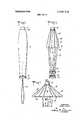
- FIG. 1is a front elevational view of anumbrella embodying the present invention illustrated in a collapsed sheathed condition
- FIG. 2is a front elevational view of the unsheathed umbrella in a condition ready for insertion into a sheath;
- FIG. 3is a front elevational fragmentary view of the upper part of the collapsed umbrella showing the umbrella cover crown in an expanded condition;
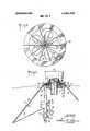
- FIG. 4is a top plan view thereof shown with the umbrella cover partially broken away;
- FIG. 5is an enlarged sectional view taken along line 5 5 in FIG. 3;
- FIG. 6is a top plan view of another form of cover crown spreader in accordance with the present invention.
- FIG. 7is an enlarged fragmentary sectional view taken along line 7 7 in FIG. 6;
- FIG. 8is a top plan view of still another form of cover crown spreader
- FIG. 9is an enlarged fragmentary end view thereof.
- FIG. 10is a fragmentary top plan view of another embodiment of the present invention shown in an open condition with the umbrella cover partially broken away;
- FIG. 11is an exploded fragmentary perspective view of the spreader notch assembly thereof.
- FIG. 12is a top plan view of a further embodiment of the present invention.
- FIG. 13is an enlarged sectional view taken along line 13 13 in FIG. 12;
- FIG. 14is a plan view of another form of spreader member.
- FIG. 15is a sectional view taken along line 15 15 in FIG. 14.
- reference numeral 10generally designates the improved collapsible umbrella which is provided with a removable tubular cover or sheath 11. Except as will be hereinafter explained umbrella 10 is of generally conventional construction such as of the nature of the umbrella structures described in US. Pat. Nos. l,3l0,48l, 2,258,196 and 2,443,772.
- Umbrella 10comprises a longitudinally contractable shaft 12 including a tubular lower section and means for releasably locking shaft 12 in an extended position.
- a handle 13mounted on the bottom of shaft 12 for movement with the shaft lower section between upper rib lock and lower rib release positions is a handle 13 provided with a circular groove in its upper face for releasable engaging the umbrella frame rib tips.
- a loop or strap member 14 of any desired designmay be connected in any suitable manner to the underface of handle 13.
- a notch 16which includes an annular base section 17 and an upwardly directed, integrally formed coaxial cylindrical socket section 18 having a threaded outer face.
- the upper end of shaft 12engages the bore in socket section 18 and'is firmly affixed therein in any suitable manner.
- Formed in the outer face of notch base 17is a peripheral groove 19 which is intersected by a plurality of regularly circumferentially spaced vertical radial slots 20.
- each rib 21including a channel shaped inner section 22 provided with an apertured flattened inner end 23 registering with a respective slot and swingably secured to notch 16 by a hinge ring or wire 24 nesting in groove 19 and engaging the apertures in rib flattened ends 23.
- the outer end of each rib section 22is peripherally closed to form a tubular guide 26.
- An outer rib section 27 terminating in a rounded tip 28extends through each guide 26 and slideably engages the channel of a respective inner rib section 22, and is movable between longitudinally extended and retracted or contracted positions.
- a channel shaped slide element 29engages each rib section 22 and terminates at opposite ends in collars 30 and 32 encircling inner rib section 22. Projecting inwardly from the side walls of slide element 29 are a pair of apertured ears 33.
- the inner end of outer rib section 27terminates in a knuckle positioned between ears 33 and a pivot pin 34 engages the knuckle, ears 33 and the one end of a spreader 36 disposed between cars 33, the opposite end of the spreader 36 being connected to a runner which slideably engages shaft 12.
- An umbrella cover 37formed of cloth or other suitable material, is of convex concave configuration and provided with a central opening the border of which is engaged by an annulus or grommet assembly 38.
- Grommet 38engages socket section 18 above notch base 17.
- the outer periphery of cover 37is suitably secured at correspondingv points to rib tip elements 28 and slide elements 29.
- the crown or central section 40 of cover 37which is delineated by points 39 and grommet 38 is free of ribs 21.
- the accordance with the present invention means 45are provided for resiliently spreading the cover crown 40 attendant the collapsing of the umbrella to facilitate its contraction into a compact state for insertion into sheath 11.
- the crown spreading meanscomprises a hub defining annulus 41 which engages socket section 18 and is sandwiched between grommet 38 and notch base 17 and locked in position by an internally threaded cap member 42 engaging the externally threaded socket section 18 and bearing on grommet 38, cap 42 being provided at its base with an outwardly directed peripheral flange.
- a plurality of resilient wire loop members 43are supported by and project outwardly from annulus 41.
- Resilient loop members 43underly cover 37 and extend from annulus 41 to points between grommet 38 and cover anchor points 39 and are medially embraced between cover 37 and alternate rib sections 22 in the umbrella open position.
- Each resilient loop 43includes an arcuate outer section 44 and inwardly converging side legs 46 the inner ends of which register with and are affixed in corresponding radial bores formed in annulus 41.
- shaft 12is longitudinally contracted, rib tips 28 being engaged by and trapped in the groove in handle 13, to raise spreaders 36, the rib sections telescoping thereby to contract the ribs and relieve the radial extension of crown 40 by slide elements 21.
- the resilient loops or fingers 43spread cover crown 40 outwardly and releasably retain it in a mushroom configuration as shown in FIGS. 3 and 5 of the drawing.
- the spreader fingerextended crown 40is then manually downwardly compressed against the influence of resilient loops 43 which may be downwardly flexed and transversely contracted to a compact longitudinally extending condition hugging the underlying upper portion of cover 37, and in this highly compact condition the collapsed umbrella is inserted, upper or cap end first, through the spread open end of sheath 11 until the cap member 42 projects through a ring 48 positioned at the remote end of tubular sheath 11.
- the umbrella 10may be extended and opened in a manner opposite to that described above.
- FIGS. 6 and 7 of the drawingsthere is illustrated another form of cover crown spreading means 50 which may be substituted for the crown spreading means in the umbrella 10, the umbrella being otherwise similar to that first described.
- the crown spreading meansincludes an annulus or hub 51 having a plurality of peripherally spaced rectangular sockets or a peripheral groove formed in the outer face thereof.
- a plurality of normally outwardly radially projecting resilient fingers 52are mounted on annulus 51 each finger 52 being formed of a resilient synthetic organic polymeric resin tube compressed and flattened at its inner end, as at 52a, the flattened ends 52a registering with and secured in the peripheral sockets in annulus 51.
- the spreader means 50is mounted on the notch member with the hub 51 sandwiched between the umbrella cover center grommet and the notch base section and with fingers 52 underlying the umbrella cover.
- the resilient fingers 52are so related and positioned on the notch relative to umbrella ribs 53 that a resilient finger 52 is medially positioned between each successive pair of umbrella ribs 53, as shown in FIG. 6.
- reference numeral 54designates a mounting annulus or hub having regularly circumferentially spaced upper and lower radial bores 56 and 57 respectively formed therein, the bores 57 being circumferentially spaced from bores 56 distances less than that between successive bores 56.
- a plurality of radially projecting sector shaped resilient wire loops 58are supported by and project radially from annulus 54.
- Each resilient loop 58includes an arcuate outer section 59 and radial legs 60 converging from the outer ends of arcuate section 59 and engaging at their inner ends a pair of remotely spaced, successive, vertically staggered upper and lower bores 56 and 57, the legs 60 of adjacent loops 58 being spaced from each other.
- loops 58lie in inclined planes so that when they are collapsed with the contraction and compression of the umbrella cover crown they are brought into unimpeded successively overlapping relationship.
- the spreader meansare so mounted on the umbrella notch and the loops 58 are so dimensioned, related and positioned that a loop 58 is medially positioned between each open umbrella rib 61 and the umbrella cover.
- reference numeral 65designates the improved umbrella which includes a notch 66, ribs 67, a cover 68 and a spreader member 69, the collapsible rib and frame structure being similar to that first described.
- Notch 66includes an annular base 70 provided with a channel 71 in its outer face to accomodate a hinge wire, and regularly circumferentially spaced radial recesses 72 intercepting channel 71 to swingably receive the inner ends of corresponding ribs 67.
- Coaxially projecting upwardly from base 70is a tubular shank 73 having an externally threaded lower portion 74 and an upper portion 76 of reduced outside diameter.
- a pair of diametrically opposite vertical grooves 78are formed in the outside face of shank 73.
- the notch 66is mounted on the umbrella shaft in the manner earlier described.
- Spreader member 69comprises a normally flat body member 79 formed as an integral unit by molding or stamping, of a resilient synthetic organic polymeric resin such as polypropylene, polyethylene or the like.
- the body member 79includes an annular hub portion 80 with outside and inside diameters about equal to these of notch base 70 and shank portion 74 and a pair of diametrically opposite inwardly directed rectangular ears 81 mating the lower parts of grooves 78.
- Radiating from hub 80are regularly angularly spaced integrally formed resilient fingers 82 equal in number to ribs 67 and having slightly outwardly diverging side edges 83 and arcuate end edges, each of the fingers 83 having a pair of transversely spaced apertures 86 located proximate its outer end.
- the ears 81, groove 78, fingers 82 and notches 72are so spatially related that when ears 81 register with grooves 78, fingers 82 medially interdigitate ribs 67.
- Each of fingers 82is coupled to the fingers adjacent thereto by easily pliable flexible connector elements which are defined by a flexible line 87 formed of any suitable natural or snythetic yarn or monofilament which extends between the successive fingers 82, interlacing the pairs of apertures 86 and suitably joined at their opposite ends.
- the length of the line 87is advantageously such that when umbrella 65 is fully opened and fingers 82 underly the umbrella cover 68, line 87 is in a substantially taut condition.
- the hub 80registers with shank 73, ears 81 engaging grooves 78, and the hub rests on base 70 with fingers 82 medially interdigitating ribs 87, and as in the first described embodiment, the central grommet engaged opening of cover 68 likewise engages shank 73 and rests on hub 80 and the assembled elements are locked in position by an internally threaded cap, corresponding to cap 42, engaging threaded shank section 74.
- the line defined connector elements 87are located between ribs 67 and cover 68.
- the operation of collapsible umbrella 65is similar to that of umbrella 10 except that in the opening of umbrella 65, ribs 67 bear on and raise the overlying connector elements 87 to urge the fingers 82 into firm engagement with the underface of cover 68.
- FIGS. 12 and 13there is illustrated another embodiment of the present invention differing from that last described primarily in that the spreader member is integrally formed with the notch.
- the notch 90includes a vertically bored cylindrical base 91 provided with a regularly notched peripheral groove 93 in its outer face corresponding to that in notch base 70. Coaxial with and projecting upwardly from base 91 is an externally threaded tubular shank 92.
- An annular hub section 94is integrally formed with the top face of base 91 and extends from shank 92 to the outer edge of base 91.
- a plurality of regularly circumferentially spaced resilient fingers 96are integrally formed with and project radially outwardly from the lower peripheral face of hub 94, each of fingers 96 having outwardly diverging side edges 97.
- the confronting inner side edges of adjacent fingersare joined by thin collapsible gussets or webs 98 which extend outwardly along a fraction of the lengths of fingers 96 and are thinner than the fingers. Pairs of transversely spaced apertures 99 are formed proximate the free ends of fingers 96 and these are interlaced by a flexible line 100 in the manner of line 87.
- a connector line similar to line 100 but interlacing pairs of apertures, located inwardly of apertures 99may be substituted for or employed in addition to connector line 100.
- the notch and spreader membermay be injection molded as a unit of the resins described above and is suitably attached to the umbrella shaft.
- the central opening in the umbrella coverengages shank 92 and is locked in position by a threaded cap.
- the umbrella employing the integral notch and spreader last describedoperates in the manner of the earlier described umbrellas.
- the spreader 110includes an annular hub 111 with an axial bore 112 and having a pair of opposite locating lugs 113 directed inwardly from the face of bore 112. integrally formed with hub 11] and projecting radially therefrom are resilient regularly spaced spokes or fingers 114 of a number equal to that of the umbrella ribs. The outer ends of the fingers 114 are connected by a thin highly flexible pliable circular web 116 concentric with the hub 111 and integrally formed with the fingers 114.
- Spreader 114is employed in the manner of spreader 69 and is similarly associated with the umbrella ribs, notch and cover.
- the high pliability and flexibility of web 116permits the collapse of fingers l 14 while transmitting the upward movement of the umbrella ribs to fingers 114.
- the flexible webmay be spaced inwardly from the outer ends of fingers 114 and that the spreader is formed by injection molding from any suitable polymeric resin.
- hub 111may be part of or integrally formed with the umbrella notch.
- a collapsible umbrella of the typehaving an elongatable shaft, a cover, elongatable ribs under the cover with the cover connected thereto at points at the periphery of the crown region and being free from the ribs for a distance inward of those points, the umbrella having a notch to which the shaft, ribs, and cover are connected, the improvement that comprises the inclusion of a spreader which comprises an integral plastic star including hub and fingers, portions of said spreader that are spaced out from the hub lying over the ribs and under the cover, the notch comprising an integral molded plastic member that includes a horizontal base disk annularly channeled at its circumferential edge, with a plurality of regularly spaced vertical recesses intersecting the annular channel, an upstanding tubular shank whose lower portion at least is externally threaded, with a pair of diametrically opposite vertical grooves in the outside face of said shank.
Landscapes
- Holders For Apparel And Elements Relating To Apparel (AREA)
Abstract
Description
Claims (1)
Priority Applications (1)
| Application Number | Priority Date | Filing Date | Title |
|---|---|---|---|
| US00234719AUS3844302A (en) | 1970-09-14 | 1972-03-15 | Collapsible umbrella |
Applications Claiming Priority (2)
| Application Number | Priority Date | Filing Date | Title |
|---|---|---|---|
| US7173270A | 1970-09-14 | 1970-09-14 | |
| US00234719AUS3844302A (en) | 1970-09-14 | 1972-03-15 | Collapsible umbrella |
Publications (1)
| Publication Number | Publication Date |
|---|---|
| US3844302Atrue US3844302A (en) | 1974-10-29 |
Family
ID=26752593
Family Applications (1)
| Application Number | Title | Priority Date | Filing Date |
|---|---|---|---|
| US00234719AExpired - LifetimeUS3844302A (en) | 1970-09-14 | 1972-03-15 | Collapsible umbrella |
Country Status (1)
| Country | Link |
|---|---|
| US (1) | US3844302A (en) |
Cited By (49)
| Publication number | Priority date | Publication date | Assignee | Title |
|---|---|---|---|---|
| US3916927A (en)* | 1972-06-03 | 1975-11-04 | Telesco Brophey Ltd | Umbrella |
| US3957070A (en)* | 1974-01-10 | 1976-05-18 | Bremshey Aktiengesellschaft | Umbrella |
| US4007743A (en)* | 1975-10-20 | 1977-02-15 | American Hospital Supply Corporation | Opening mechanism for umbrella-like intravascular shunt defect closure device |
| US6152144A (en)* | 1998-11-06 | 2000-11-28 | Appriva Medical, Inc. | Method and device for left atrial appendage occlusion |
| US20020183823A1 (en)* | 2001-06-04 | 2002-12-05 | Ramesh Pappu | Cardiac stimulating apparatus having a blood clot filter and atrial pacer |
| US6551303B1 (en) | 1999-10-27 | 2003-04-22 | Atritech, Inc. | Barrier device for ostium of left atrial appendage |
| US6652555B1 (en) | 1999-10-27 | 2003-11-25 | Atritech, Inc. | Barrier device for covering the ostium of left atrial appendage |
| US6652556B1 (en) | 1999-10-27 | 2003-11-25 | Atritech, Inc. | Filter apparatus for ostium of left atrial appendage |
| US20040044361A1 (en)* | 1998-11-06 | 2004-03-04 | Frazier Andrew G.C. | Detachable atrial appendage occlusion balloon |
| US6994092B2 (en) | 1999-11-08 | 2006-02-07 | Ev3 Sunnyvale, Inc. | Device for containing embolic material in the LAA having a plurality of tissue retention structures |
| US7011671B2 (en) | 2001-07-18 | 2006-03-14 | Atritech, Inc. | Cardiac implant device tether system and method |
| US7044134B2 (en) | 1999-11-08 | 2006-05-16 | Ev3 Sunnyvale, Inc | Method of implanting a device in the left atrial appendage |
| US7128073B1 (en) | 1998-11-06 | 2006-10-31 | Ev3 Endovascular, Inc. | Method and device for left atrial appendage occlusion |
| US7169164B2 (en) | 2000-09-21 | 2007-01-30 | Atritech, Inc. | Apparatus for implanting devices in atrial appendages |
| US7549983B2 (en) | 1999-09-20 | 2009-06-23 | Atritech, Inc. | Method of closing an opening in a wall of the heart |
| US7575586B2 (en) | 1998-01-30 | 2009-08-18 | St. Jude Medical Atg, Inc. | Medical graft connector or plug structures, and methods of making and installing same |
| US7597704B2 (en) | 2003-04-28 | 2009-10-06 | Atritech, Inc. | Left atrial appendage occlusion device with active expansion |
| US20100069954A1 (en)* | 2003-04-11 | 2010-03-18 | St. Jude Medical Cardiovascular Division | Closure devices, related delivery methods and related methods of use |
| US7691128B2 (en) | 2002-05-06 | 2010-04-06 | St. Jude Medical, Cardiology Division, Inc. | PFO closure devices and related methods of use |
| US7717937B2 (en) | 2001-06-01 | 2010-05-18 | St. Jude Medical, Cardiology Division, Inc. | Closure devices, related delivery methods and tools, and related methods of use |
| US7735493B2 (en) | 2003-08-15 | 2010-06-15 | Atritech, Inc. | System and method for delivering a left atrial appendage containment device |
| US7972359B2 (en) | 2005-09-16 | 2011-07-05 | Atritech, Inc. | Intracardiac cage and method of delivering same |
| US8372112B2 (en) | 2003-04-11 | 2013-02-12 | St. Jude Medical, Cardiology Division, Inc. | Closure devices, related delivery methods, and related methods of use |
| US8801746B1 (en) | 2004-05-04 | 2014-08-12 | Covidien Lp | System and method for delivering a left atrial appendage containment device |
| EP3045070A1 (en)* | 2015-01-16 | 2016-07-20 | Fox International Group Limited | A canopy |
| US9474516B2 (en) | 2011-11-08 | 2016-10-25 | Boston Scientific Scimed, Inc. | Handle assembly for a left atrial appendage occlusion device |
| US9730701B2 (en) | 2014-01-16 | 2017-08-15 | Boston Scientific Scimed, Inc. | Retrieval wire centering device |
| US9883936B2 (en) | 2002-01-25 | 2018-02-06 | Boston Scientific Scimed, Inc | Atrial appendage blood filtration systems |
| US10076335B2 (en) | 2005-12-01 | 2018-09-18 | Atritech, Inc. | Apparatus for delivering an implant without bias to a left atrial appendage |
| US10667896B2 (en) | 2015-11-13 | 2020-06-02 | Cardiac Pacemakers, Inc. | Bioabsorbable left atrial appendage closure with endothelialization promoting surface |
| US20200222172A1 (en)* | 2019-01-11 | 2020-07-16 | Varun Shetty | Method and system for reducing pulmonary flow |
| US10952741B2 (en) | 2017-12-18 | 2021-03-23 | Boston Scientific Scimed, Inc. | Occlusive device with expandable member |
| US11123079B2 (en) | 2018-06-08 | 2021-09-21 | Boston Scientific Scimed, Inc. | Occlusive device with actuatable fixation members |
| US11241239B2 (en) | 2018-05-15 | 2022-02-08 | Boston Scientific Scimed, Inc. | Occlusive medical device with charged polymer coating |
| US11331104B2 (en) | 2018-05-02 | 2022-05-17 | Boston Scientific Scimed, Inc. | Occlusive sealing sensor system |
| US11382635B2 (en) | 2018-07-06 | 2022-07-12 | Boston Scientific Scimed, Inc. | Occlusive medical device |
| US11413048B2 (en) | 2018-01-19 | 2022-08-16 | Boston Scientific Scimed, Inc. | Occlusive medical device with delivery system |
| US11432809B2 (en) | 2017-04-27 | 2022-09-06 | Boston Scientific Scimed, Inc. | Occlusive medical device with fabric retention barb |
| US11540838B2 (en) | 2019-08-30 | 2023-01-03 | Boston Scientific Scimed, Inc. | Left atrial appendage implant with sealing disk |
| US11596533B2 (en) | 2018-08-21 | 2023-03-07 | Boston Scientific Scimed, Inc. | Projecting member with barb for cardiovascular devices |
| US11672541B2 (en) | 2018-06-08 | 2023-06-13 | Boston Scientific Scimed, Inc. | Medical device with occlusive member |
| US11903589B2 (en) | 2020-03-24 | 2024-02-20 | Boston Scientific Scimed, Inc. | Medical system for treating a left atrial appendage |
| US11944314B2 (en) | 2019-07-17 | 2024-04-02 | Boston Scientific Scimed, Inc. | Left atrial appendage implant with continuous covering |
| US12023036B2 (en) | 2020-12-18 | 2024-07-02 | Boston Scientific Scimed, Inc. | Occlusive medical device having sensing capabilities |
| US12318092B2 (en) | 2021-06-22 | 2025-06-03 | Boston Scientific Scimed, Inc. | Left atrial appendage implant |
| US12329500B2 (en) | 2020-11-30 | 2025-06-17 | Boston Scientific Scimed, Inc. | Implantable passive mean pressure sensor |
| US12349918B2 (en) | 2021-09-08 | 2025-07-08 | Boston Scientific Scimed, Inc. | Multi-sharpness split top soft tissue anchors |
| US12383278B2 (en) | 2021-07-08 | 2025-08-12 | Boston Scientific Scimed, Inc. | Left atrial appendage closure device |
| US12383201B2 (en) | 2021-02-03 | 2025-08-12 | Boston Scientific Scimed, Inc. | Medical system for treating a left atrial appendage |
Citations (8)
| Publication number | Priority date | Publication date | Assignee | Title |
|---|---|---|---|---|
| US2258196A (en)* | 1941-01-11 | 1941-10-07 | John A H Siers | Umbrella |
| US2443772A (en)* | 1945-01-18 | 1948-06-22 | Mappin Walter Levison | Collapsible umbrella |
| US2465140A (en)* | 1947-03-07 | 1949-03-22 | Vila Alejo | Parasol |
| US2475446A (en)* | 1945-12-07 | 1949-07-05 | David M Cohen | Umbrella construction |
| US2864389A (en)* | 1956-04-09 | 1958-12-16 | Hettrick Mfg Co | Umbrella tent |
| US3146785A (en)* | 1961-05-26 | 1964-09-01 | Iwashita Wasaku | Umbrella |
| US3177883A (en)* | 1962-01-08 | 1965-04-13 | Finkel Umbrella Frame Company | Unitary umbrella frames |
| US3693643A (en)* | 1969-12-18 | 1972-09-26 | Bremshey & Co | Collapsible umbrella |
- 1972
- 1972-03-15USUS00234719Apatent/US3844302A/ennot_activeExpired - Lifetime
Patent Citations (8)
| Publication number | Priority date | Publication date | Assignee | Title |
|---|---|---|---|---|
| US2258196A (en)* | 1941-01-11 | 1941-10-07 | John A H Siers | Umbrella |
| US2443772A (en)* | 1945-01-18 | 1948-06-22 | Mappin Walter Levison | Collapsible umbrella |
| US2475446A (en)* | 1945-12-07 | 1949-07-05 | David M Cohen | Umbrella construction |
| US2465140A (en)* | 1947-03-07 | 1949-03-22 | Vila Alejo | Parasol |
| US2864389A (en)* | 1956-04-09 | 1958-12-16 | Hettrick Mfg Co | Umbrella tent |
| US3146785A (en)* | 1961-05-26 | 1964-09-01 | Iwashita Wasaku | Umbrella |
| US3177883A (en)* | 1962-01-08 | 1965-04-13 | Finkel Umbrella Frame Company | Unitary umbrella frames |
| US3693643A (en)* | 1969-12-18 | 1972-09-26 | Bremshey & Co | Collapsible umbrella |
Cited By (95)
| Publication number | Priority date | Publication date | Assignee | Title |
|---|---|---|---|---|
| US3916927A (en)* | 1972-06-03 | 1975-11-04 | Telesco Brophey Ltd | Umbrella |
| US3957070A (en)* | 1974-01-10 | 1976-05-18 | Bremshey Aktiengesellschaft | Umbrella |
| US4007743A (en)* | 1975-10-20 | 1977-02-15 | American Hospital Supply Corporation | Opening mechanism for umbrella-like intravascular shunt defect closure device |
| US7575586B2 (en) | 1998-01-30 | 2009-08-18 | St. Jude Medical Atg, Inc. | Medical graft connector or plug structures, and methods of making and installing same |
| US7722641B2 (en) | 1998-11-06 | 2010-05-25 | Atritech, Inc. | Filter mesh for preventing passage of embolic material form an atrial appendage |
| US8834519B2 (en) | 1998-11-06 | 2014-09-16 | Artritech, Inc. | Method and device for left atrial appendage occlusion |
| US8535343B2 (en) | 1998-11-06 | 2013-09-17 | Atritech, Inc. | Method for left atrial appendage occlusion |
| US8523897B2 (en) | 1998-11-06 | 2013-09-03 | Atritech, Inc. | Device for left atrial appendage occlusion |
| US7152605B2 (en) | 1998-11-06 | 2006-12-26 | Ev3 Endovascular, Inc. | Adjustable left atrial appendage implant deployment system |
| US20040044361A1 (en)* | 1998-11-06 | 2004-03-04 | Frazier Andrew G.C. | Detachable atrial appendage occlusion balloon |
| US8080032B2 (en) | 1998-11-06 | 2011-12-20 | Atritech, Inc. | Method and device for left atrial appendage occlusion |
| US20110218566A1 (en)* | 1998-11-06 | 2011-09-08 | Atritech, Inc. | Method for left atrial appendage occlusion |
| US7128073B1 (en) | 1998-11-06 | 2006-10-31 | Ev3 Endovascular, Inc. | Method and device for left atrial appendage occlusion |
| US7713282B2 (en) | 1998-11-06 | 2010-05-11 | Atritech, Inc. | Detachable atrial appendage occlusion balloon |
| US9168043B2 (en) | 1998-11-06 | 2015-10-27 | Atritech, Inc. | Method for left atrial appendage occlusion |
| US6152144A (en)* | 1998-11-06 | 2000-11-28 | Appriva Medical, Inc. | Method and device for left atrial appendage occlusion |
| US7549983B2 (en) | 1999-09-20 | 2009-06-23 | Atritech, Inc. | Method of closing an opening in a wall of the heart |
| US9421004B2 (en) | 1999-09-20 | 2016-08-23 | Atritech Inc. | Method of closing an opening in a wall of the heart |
| US8221445B2 (en) | 1999-10-27 | 2012-07-17 | Atritech, Inc. | Barrier device for ostium of left atrial appendage |
| US6949113B2 (en) | 1999-10-27 | 2005-09-27 | Atritech, Inc. | Barrier device for ostium of left atrial appendage |
| US6730108B2 (en) | 1999-10-27 | 2004-05-04 | Atritech, Inc. | Barrier device for ostium of left atrial appendage |
| US8685055B2 (en) | 1999-10-27 | 2014-04-01 | Atritech, Inc. | Filter apparatus for ostium of left atrial appendage |
| US10893926B2 (en) | 1999-10-27 | 2021-01-19 | Atritech, Inc. | Filter apparatus for ostium of left atrial appendage |
| US6551303B1 (en) | 1999-10-27 | 2003-04-22 | Atritech, Inc. | Barrier device for ostium of left atrial appendage |
| US6652555B1 (en) | 1999-10-27 | 2003-11-25 | Atritech, Inc. | Barrier device for covering the ostium of left atrial appendage |
| US6689150B1 (en) | 1999-10-27 | 2004-02-10 | Atritech, Inc. | Filter apparatus for ostium of left atrial appendage |
| US6652556B1 (en) | 1999-10-27 | 2003-11-25 | Atritech, Inc. | Filter apparatus for ostium of left atrial appendage |
| US9132000B2 (en) | 1999-10-27 | 2015-09-15 | Atritech Inc. | Filter apparatus for ostium of left atrial appendage |
| US7727189B2 (en) | 1999-10-27 | 2010-06-01 | Atritech, Inc. | Filter apparatus for ostium of left atrial appendage |
| US8287563B2 (en) | 1999-11-08 | 2012-10-16 | Atritech, Inc. | Implant retrieval system |
| US6994092B2 (en) | 1999-11-08 | 2006-02-07 | Ev3 Sunnyvale, Inc. | Device for containing embolic material in the LAA having a plurality of tissue retention structures |
| US8663273B2 (en) | 1999-11-08 | 2014-03-04 | Atritech, Inc. | Method of implanting an adjustable occlusion device |
| US9943299B2 (en) | 1999-11-08 | 2018-04-17 | Atritech, Inc. | Method of implanting an adjustable occlusion device |
| US7044134B2 (en) | 1999-11-08 | 2006-05-16 | Ev3 Sunnyvale, Inc | Method of implanting a device in the left atrial appendage |
| US7192439B2 (en) | 1999-11-08 | 2007-03-20 | Ev3 Endovascular, Inc. | Method of removing an implanted device |
| US8043329B2 (en) | 1999-11-08 | 2011-10-25 | Atritech, Inc. | Method of implanting an adjustable occlusion device |
| US8323309B2 (en) | 1999-11-08 | 2012-12-04 | Atritech, Inc. | Adjustable left atrial appendage implant |
| US7169164B2 (en) | 2000-09-21 | 2007-01-30 | Atritech, Inc. | Apparatus for implanting devices in atrial appendages |
| US8777985B2 (en) | 2001-06-01 | 2014-07-15 | St. Jude Medical, Cardiology Division, Inc. | Closure devices, related delivery methods and tools, and related methods of use |
| US9078630B2 (en) | 2001-06-01 | 2015-07-14 | St. Jude Medical, Cardiology Division, Inc. | Closure devices, related delivery methods and tools, and related methods of use |
| US20100234882A1 (en)* | 2001-06-01 | 2010-09-16 | St. Jude Medical, Cardiology Division, Inc. | Closure devices, related delivery methods and tools, and related methods of use |
| US7717937B2 (en) | 2001-06-01 | 2010-05-18 | St. Jude Medical, Cardiology Division, Inc. | Closure devices, related delivery methods and tools, and related methods of use |
| US6941169B2 (en) | 2001-06-04 | 2005-09-06 | Albert Einstein Healthcare Network | Cardiac stimulating apparatus having a blood clot filter and atrial pacer |
| US20020183823A1 (en)* | 2001-06-04 | 2002-12-05 | Ramesh Pappu | Cardiac stimulating apparatus having a blood clot filter and atrial pacer |
| US7011671B2 (en) | 2001-07-18 | 2006-03-14 | Atritech, Inc. | Cardiac implant device tether system and method |
| US9883936B2 (en) | 2002-01-25 | 2018-02-06 | Boston Scientific Scimed, Inc | Atrial appendage blood filtration systems |
| US10751158B2 (en) | 2002-01-25 | 2020-08-25 | Atritech, Inc. | Atrial appendage blood filtration systems |
| US7976564B2 (en) | 2002-05-06 | 2011-07-12 | St. Jude Medical, Cardiology Division, Inc. | PFO closure devices and related methods of use |
| US20100234881A1 (en)* | 2002-05-06 | 2010-09-16 | St. Jude Medical, Cardiology Division, Inc. | Pfo closure devices and related methods of use |
| US7691128B2 (en) | 2002-05-06 | 2010-04-06 | St. Jude Medical, Cardiology Division, Inc. | PFO closure devices and related methods of use |
| US20100069954A1 (en)* | 2003-04-11 | 2010-03-18 | St. Jude Medical Cardiovascular Division | Closure devices, related delivery methods and related methods of use |
| US8372112B2 (en) | 2003-04-11 | 2013-02-12 | St. Jude Medical, Cardiology Division, Inc. | Closure devices, related delivery methods, and related methods of use |
| US8574264B2 (en) | 2003-04-11 | 2013-11-05 | St. Jude Medical, Cardiology Division, Inc. | Method for retrieving a closure device |
| US8382796B2 (en) | 2003-04-11 | 2013-02-26 | St. Jude Medical, Cardiology Division, Inc. | Closure devices, related delivery methods and related methods of use |
| US7597704B2 (en) | 2003-04-28 | 2009-10-06 | Atritech, Inc. | Left atrial appendage occlusion device with active expansion |
| US7735493B2 (en) | 2003-08-15 | 2010-06-15 | Atritech, Inc. | System and method for delivering a left atrial appendage containment device |
| US9314249B2 (en) | 2004-05-04 | 2016-04-19 | Covidien Lp | System and method for delivering a left atrial appendage containment device |
| US8801746B1 (en) | 2004-05-04 | 2014-08-12 | Covidien Lp | System and method for delivering a left atrial appendage containment device |
| US7972359B2 (en) | 2005-09-16 | 2011-07-05 | Atritech, Inc. | Intracardiac cage and method of delivering same |
| US10143458B2 (en) | 2005-09-16 | 2018-12-04 | Atritech, Inc. | Intracardiac cage and method of delivering same |
| US9445895B2 (en) | 2005-09-16 | 2016-09-20 | Atritech, Inc. | Intracardiac cage and method of delivering same |
| US10898198B2 (en) | 2005-12-01 | 2021-01-26 | Atritech, Inc. | Apparatus for delivering an implant without bias to a left atrial appendage |
| US10076335B2 (en) | 2005-12-01 | 2018-09-18 | Atritech, Inc. | Apparatus for delivering an implant without bias to a left atrial appendage |
| US9474516B2 (en) | 2011-11-08 | 2016-10-25 | Boston Scientific Scimed, Inc. | Handle assembly for a left atrial appendage occlusion device |
| US12193678B2 (en) | 2014-01-16 | 2025-01-14 | Boston Scientific Scimed, Inc. | Retrieval wire centering device |
| US11413047B2 (en) | 2014-01-16 | 2022-08-16 | Cardiac Pacemakers, Inc. | Occlusive medical implant |
| US10463377B2 (en) | 2014-01-16 | 2019-11-05 | Boston Scientific Scimed, Inc. | Retrieval wire centering device |
| US9730701B2 (en) | 2014-01-16 | 2017-08-15 | Boston Scientific Scimed, Inc. | Retrieval wire centering device |
| EP3045070A1 (en)* | 2015-01-16 | 2016-07-20 | Fox International Group Limited | A canopy |
| US10667896B2 (en) | 2015-11-13 | 2020-06-02 | Cardiac Pacemakers, Inc. | Bioabsorbable left atrial appendage closure with endothelialization promoting surface |
| US12082797B2 (en) | 2017-04-27 | 2024-09-10 | Boston Scientific Scimed, Inc. | Occlusive medical device with fabric retention barb |
| US11432809B2 (en) | 2017-04-27 | 2022-09-06 | Boston Scientific Scimed, Inc. | Occlusive medical device with fabric retention barb |
| US10952741B2 (en) | 2017-12-18 | 2021-03-23 | Boston Scientific Scimed, Inc. | Occlusive device with expandable member |
| US11925356B2 (en) | 2017-12-18 | 2024-03-12 | Boston Scientific Scimed, Inc. | Occlusive device with expandable member |
| US11413048B2 (en) | 2018-01-19 | 2022-08-16 | Boston Scientific Scimed, Inc. | Occlusive medical device with delivery system |
| US11331104B2 (en) | 2018-05-02 | 2022-05-17 | Boston Scientific Scimed, Inc. | Occlusive sealing sensor system |
| US11241239B2 (en) | 2018-05-15 | 2022-02-08 | Boston Scientific Scimed, Inc. | Occlusive medical device with charged polymer coating |
| US11890018B2 (en) | 2018-06-08 | 2024-02-06 | Boston Scientific Scimed, Inc. | Occlusive device with actuatable fixation members |
| US11123079B2 (en) | 2018-06-08 | 2021-09-21 | Boston Scientific Scimed, Inc. | Occlusive device with actuatable fixation members |
| US11672541B2 (en) | 2018-06-08 | 2023-06-13 | Boston Scientific Scimed, Inc. | Medical device with occlusive member |
| US11382635B2 (en) | 2018-07-06 | 2022-07-12 | Boston Scientific Scimed, Inc. | Occlusive medical device |
| US12232736B2 (en) | 2018-07-06 | 2025-02-25 | Boston Scientific Scimed, Inc | Occlusive medical device |
| US11596533B2 (en) | 2018-08-21 | 2023-03-07 | Boston Scientific Scimed, Inc. | Projecting member with barb for cardiovascular devices |
| US20200222172A1 (en)* | 2019-01-11 | 2020-07-16 | Varun Shetty | Method and system for reducing pulmonary flow |
| US11963864B2 (en)* | 2019-01-11 | 2024-04-23 | Varun Shetty | Method and system for reducing pulmonary flow |
| US11944314B2 (en) | 2019-07-17 | 2024-04-02 | Boston Scientific Scimed, Inc. | Left atrial appendage implant with continuous covering |
| US11540838B2 (en) | 2019-08-30 | 2023-01-03 | Boston Scientific Scimed, Inc. | Left atrial appendage implant with sealing disk |
| US11903589B2 (en) | 2020-03-24 | 2024-02-20 | Boston Scientific Scimed, Inc. | Medical system for treating a left atrial appendage |
| US12329500B2 (en) | 2020-11-30 | 2025-06-17 | Boston Scientific Scimed, Inc. | Implantable passive mean pressure sensor |
| US12023036B2 (en) | 2020-12-18 | 2024-07-02 | Boston Scientific Scimed, Inc. | Occlusive medical device having sensing capabilities |
| US12383201B2 (en) | 2021-02-03 | 2025-08-12 | Boston Scientific Scimed, Inc. | Medical system for treating a left atrial appendage |
| US12318092B2 (en) | 2021-06-22 | 2025-06-03 | Boston Scientific Scimed, Inc. | Left atrial appendage implant |
| US12336715B2 (en) | 2021-06-22 | 2025-06-24 | Boston Scientific Scimed, Inc. | Left atrial appendage implant |
| US12383278B2 (en) | 2021-07-08 | 2025-08-12 | Boston Scientific Scimed, Inc. | Left atrial appendage closure device |
| US12349918B2 (en) | 2021-09-08 | 2025-07-08 | Boston Scientific Scimed, Inc. | Multi-sharpness split top soft tissue anchors |
Similar Documents
| Publication | Publication Date | Title |
|---|---|---|
| US3844302A (en) | Collapsible umbrella | |
| US3435836A (en) | Umbrella construction | |
| US4144900A (en) | Umbrella | |
| US3534752A (en) | Umbrella construction | |
| US2782795A (en) | Beach and garden umbrella and mechanism for opening and closing same | |
| US2788792A (en) | Wind-resistant reversible umbrella | |
| US3957070A (en) | Umbrella | |
| US4259974A (en) | Umbrella | |
| US4317553A (en) | Projection screen stand | |
| GB2341794A (en) | Spread position securing device for beach parasols | |
| US2725066A (en) | Reversible umbrella | |
| US4284091A (en) | Hair curler | |
| US4474200A (en) | Umbrella with oval canopy | |
| US5048550A (en) | Structure of triple-folding umbrella skeleton | |
| US3746024A (en) | Folding umbrella | |
| US2492376A (en) | Umbrella | |
| US4736761A (en) | Umbrella | |
| US7509965B2 (en) | Ventilated umbrella | |
| US2111578A (en) | Umbrella construction | |
| US6276380B1 (en) | Anti-wind umbrellas | |
| US3683948A (en) | Umbrella of collapsible construction | |
| EP0298623A2 (en) | Toy umbrella | |
| US5427130A (en) | Parasol structure | |
| US3073327A (en) | Umbrellas | |
| US2853080A (en) | Expanding and retracting hair curler |
Legal Events
| Date | Code | Title | Description |
|---|---|---|---|
| AS | Assignment | Owner name:KNIRPS INTERNATIONAL GMBH, WEYERSTRASSE 277, D-565 Free format text:ASSIGNMENT OF ASSIGNORS INTEREST.;ASSIGNOR:KNRIPS CANADA INC.;REEL/FRAME:004163/0425 Effective date:19830713 Owner name:KNIRPS CANADA INC. Free format text:MERGER;ASSIGNOR:KNIRPS CANADA INC. KNIRPS CANADA LTD./LTEE;REEL/FRAME:004187/0404 Effective date:19801009 Owner name:KNIRPS CANADA LTD.- KNIRPS CANADA LTEE Free format text:CHANGE OF NAME;ASSIGNOR:TELESCO BROPHEY LIMITED;REEL/FRAME:004187/0408 Effective date:19760505 Owner name:KNIRPS CANADA INC., STATELESS Free format text:MERGER;ASSIGNOR:KNIRPS CANADA INC. KNIRPS CANADA LTD./LTEE;REEL/FRAME:004187/0404 Effective date:19801009 Owner name:KNIRPS CANADA LTD.- KNIRPS CANADA LTEE, STATELESS Free format text:CHANGE OF NAME;ASSIGNOR:TELESCO BROPHEY LIMITED;REEL/FRAME:004187/0408 Effective date:19760505 |