US3828672A - Apparatus for fitting flexible printing plates and rigging to printing press cylinders - Google Patents
Apparatus for fitting flexible printing plates and rigging to printing press cylindersDownload PDFInfo
- Publication number
- US3828672A US3828672AUS00298376AUS29837672AUS3828672AUS 3828672 AUS3828672 AUS 3828672AUS 00298376 AUS00298376 AUS 00298376AUS 29837672 AUS29837672 AUS 29837672AUS 3828672 AUS3828672 AUS 3828672A
- Authority
- US
- United States
- Prior art keywords
- plate
- cylinder
- printing press
- printing
- roller
- Prior art date
- Legal status (The legal status is an assumption and is not a legal conclusion. Google has not performed a legal analysis and makes no representation as to the accuracy of the status listed.)
- Expired - Lifetime
Links
Images


Classifications
- B—PERFORMING OPERATIONS; TRANSPORTING
- B41—PRINTING; LINING MACHINES; TYPEWRITERS; STAMPS
- B41F—PRINTING MACHINES OR PRESSES
- B41F27/00—Devices for attaching printing elements or formes to supports
- B41F27/12—Devices for attaching printing elements or formes to supports for attaching flexible printing formes
- B41F27/1218—Devices for attaching printing elements or formes to supports for attaching flexible printing formes comprising printing plate tensioning devices
- B41F27/1225—Devices for attaching printing elements or formes to supports for attaching flexible printing formes comprising printing plate tensioning devices moving in the printing plate end substantially rectilinearly
- B41F27/1231—Devices for attaching printing elements or formes to supports for attaching flexible printing formes comprising printing plate tensioning devices moving in the printing plate end substantially rectilinearly by translatory motion substantially tangential to support surface
- B—PERFORMING OPERATIONS; TRANSPORTING
- B41—PRINTING; LINING MACHINES; TYPEWRITERS; STAMPS
- B41F—PRINTING MACHINES OR PRESSES
- B41F27/00—Devices for attaching printing elements or formes to supports
- B41F27/12—Devices for attaching printing elements or formes to supports for attaching flexible printing formes
- B41F27/1206—Feeding to or removing from the forme cylinder
Definitions
- This printing pressincludes improved mechanism for clamping the edges of a flexible printing plate adjacent the leading and trailing edges of the saddle of a printing press cylinder.
- An auxiliary roll mechanismpermits the flexible printing plate or rigging sheet to be held smooth and under tension during its installation on the cylinder.
- the inventioncomprises three principal parts; namely: I
- a clampfor holding the leading edge of a flexible printing plate or flexible rigging on the periphery of a printing cylinder
- the mechanism for clamping the leading edge of the plate to the cylinder peripherymay be of any suitable conventional construction.
- the mechanism for holding the plate smooth and under tension during installationincludes an auxiliary roller, a carriage supporting the roller and movable between:
- the carriageis pivotally supported for movement between these three positions, and provision is made for locking the carriage in any one of the three positions.
- the carriageincludes a pair of spaced parallel arms, with an extension on each arm slidable on the arm.
- the pivots for the auxiliary rollerare on the extensions.
- Hydraulic motor meansare provided on the arms for moving the extensions so that the roller may apply substantial pressure either to the pressure cylinder or the plate cylinder, so as to maintain substantial tension on a plate or sheet mounted thereon and clamped at the leading edge only.
- Meansare provided to limit the movement the channeled jaw.
- These railshave flanges which are received in the channels. Roller bearings are captured between the flanges and the bottoms of the channels.
- a row of spaced coil springsbiases the lower jawtoward a position in which the plate is under tension.
- the lower jaw and the upper jaw assembled with itmay be moved against the tension of the springs to a tension releasing position by means of a single cam joumaled on a pin fixed to the middle of the cylinder and rotatable by means of an external tool.
- the follower for the camcomprises a roller bearing rotatable on an 'arbor fixed on the lower jaw.
- the camis provided with a concave notch which engages the follower when the plate tension is relieved, so that the cam and follower remain securely in their tension relieving positions, until the cam is rotated by the external tool.
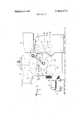
- FIG. 1is a fragmentary elevationalview of an intaglio printing press embodying the invention, with certain parts broken away.
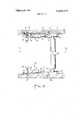
- FIG. 2is a fragmentary sectional view taken along the line 2-2 of FIGS. 1 and 3, on an enlargedscale.
- FIG. 3is a sectional view taken along the line 3-3 of FIG. 2, with certain parts omitted.
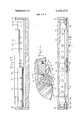
- FIG. 4is an enlarged fragmentary sectional view showing the mechanism for clamping the printing plates to the plate cylinder.
- FIG. 5is an exploded fragmentary view showing the mechanism for clamping the leading edge of the plate to the plate cylinder.
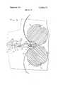
- FIG. 6is a sectional view taken along the line 6--6 of FIG. 4.
- FIG. 7is a sectional view taken along the line 7-7 of FIG. 6.
- FIG. 8is a sectional view taken along the line 8-8 of FIG. 6, showing the parts in positions in which the printing plate is under tension.
- FIG. 9is a view similar to FIG. 8, showing the parts in positions in which the plate tension is relieved.
- FIG. 10is a view taken along the line 10-10 of FIG. 4.
- FIG. 11is a sectional view on an enlarged scale, corresponding to a left to right reversed view of the lower portion of FIG. 4, with a cover for the clamping mechanisms added.
- FIG. 12is a sectional view taken along the line 12-12 of FIG. 11. 7
- the press illustratedincludes a front vertical frame member 1 and a rear vertical frame member 2 (FIG. 2).
- the press illustratedis a multicolor press.
- the ink applying mechanismincludes a carriage (FIG. 1) on which are mounted three ink reservoirs l1, l2 and 13 connected by ink conveying roller trains l5, l6 and 17 to rollers 20, 21 and 22, which transfer the ink to the plate on the cylinder 3.
- the rollers 20, 21 and 22are contoured, so that each contacts a portion only of the surface of the cylinder 3. Typically, only one color of ink will be applied to any given portion of the surface of the plate, although it may be arranged that colors overlap, if desired.
- the plate carrying cylinder 3turns clockwise, as viewed in FIG. 1.
- a wiping roll 25is rotatably mounted so that it runs with its periphery in contact with the plate cylinder 3, and also becomes immersed in a suitable solvent in a tank 26.
- the wiping roll 25removes the ink from the surface of the plate on the printing cylinder, between the lines on the plate, so that as the plate approaches the nip of the cylinders 3 and 4, the
- the plate cylinder 3is driven by a motor 27 through a multiple V-belt drive 28 and a suitable gear train (not shown).
- Conveyor 9is driven from the plate cylinder 5 through a bevel pass shown at 29 in FIG. 1.
- the wiping rollis driven by a motor 30, which may be controlled as described in our copending application, Ser. No. 173,555, mentioned above.
- An auxiliary roller 32is rotatably supported on a pivotally mounted carriage 33.
- the carriage 33comprises a pair of arms 34, 35, which are pivotally mounted on trunnions 36, 37, fixed on the inner sides of the front and rear frame members 1 and 2.
- the T-shaped head 35ahas formed therein an arcuate slot 35b which receives the shank of a screw 40, which is threadedly received in the frame member 2. By tightening the screw 40, the arm 35 may be locked in any angular position.
- each of the arms 34, 35is provided near its outer end with a housing 41, which encloses a locating pin 42.
- Each pin 42has an enlarged head, tapered at its end, and is receivable in any one of three holes 43, formed in the frame members 1 and 2.
- a spring 44is held in compression between a shoulder on the head 42 of the locating pin and the inner end of the housing 1, and biases the locating pin toward the position where its head is received in one of the holes 43.
- the outer end of the shank of pin 42extends through the top of the casing 41 and is provided at its inner end with a handle 45 by means of which the head 42 may be withdrawn from one of the holds 43 for the purpose of shifting the operating position of the carriage 33.
- the arms 34, 35are provided with a pair of exten- .sions 46, slidable in suitable channels provided in the arms 34, 35.
- the extensions 46are operated by means of hydraulic motors 47, which are pivotally fixed at their left-hand ends to posts 48 fastened to the arms 34, 35.
- the hydraulic motors 47operate piston rods 50, which are pivotally fixed to the extensions 46.
- a pair of stops 51are fixed on the frame members 1 and 2 in alignment with the ends of the extensions 46, when the carriage 33 is in its retracted position, as shown in full lines in FIG. 3.
- Each stop 51is provided with an adjustable screw 52, by means of which the stop positions of the extensions 46 may be varied as required.
- the carriage 33In the normal running condition of the press, the carriage 33 is in its retracted position, shown in full lines in FIG. 3, so that the extensions 46 engage their stop screws 52, and the surface of the roller 32 does not engage the surface of either the plate cylinder 5 or the pressure cylinder 4.
- the leading edge of the plateis first fastened to the plate cylinder 5 by means of a clamp generally indicated at in FIG. 3.
- the carriage 33is then released from its position illustrated in full lines and is turned clockwise from that position about the trunnions 36 to a position in which the pins 42 engage the uppermost holes 43 and the roller 32 engages the printing plate 61 adjacent the leading edge of the saddle St: on which the plate is to be mounted.
- Theplate cylinder 5is then rotated counterclockwise, with the roller 32 holding the plate 61 smoothly and firmly against the saddle 5a.
- a clamping mechanism 62shown in detail in FIGS. 4 and 6-12.
- a similar procedureis used in applying a flexible rigging sheet to the pressure cylinder 4.
- the clamps 63 and 64 used respectively at the leading and trailing edges of the rigging sheet on the pressure cylinder 4need not be exactly like the clamps 60 and 62 of the plate cylinder, since the location of the rigging sheet on the pressure cylinder 4 does not involve the degree of precision required for the location of the plate 61 on the plate cylinder 5.
- the clamping mechanism 60 for the leading edge of the printing plate 61is best seen in these two figures.
- This clamping mechanism 60includes an inner jaw 65 recessed in and fastened to the plate cylinder 5 by screws 69 (FIG. 10), and an outer jaw 66, which may be fastened to the inner jaw 65 by means of a series of spaced machine screws 67.
- Outer jaw 66is provided on its inner face, at its margin remote from the plate 61, with a projecting flat surface 68, whose thickness is less than the thickness of the plate 61, so that the jaws 65 and 66 will tend to contact on the inner teeth of the jaws when in their clamped positions.
- the face of the jaw 66 which engages the plate 61is provided with a plurality of rows of sharp pointed teeth 66a near the edge of the plate 61, and with a plurality of rows of teeth 66b having flattened or truncated points, engaging the plate 61 farther from the edge than the sharp points 660.
- This constructioninsures that the marginal edge of plate 61 will be held tightly by the sharp points 66a, and allows the plate 61 to shift laterally where it is located under the flat points 66b.
- the outer jaw 66is also provided with a plurality of spaced openings 66c (FIGS. 4, 8 and 9), which loosely receive the heads of locating pins 70, which are firmly fixed in the lower jaws 65, and which are received in openings in the plate 61 to fix its location precisely and accurately with respectto the cylinder 5.
- the trailing edge clamping mechanism 62includes an inner jaw 71 and an outer jaw 72.
- the jaws 71 and 72are located in a recess 73 formed in the outer surface of the cylinder between the plate supporting saddles.
- the inner jaw 71does not touch the bottom of that recess, but is supported outwardly from it, as clearly appears in the drawings, especially FIGS. 4 and 7-9.
- the inner jaw 71is provided at each end with a channel 71a (FIG. 7), extending parallel to the inner and outer surfaces of the jaw.
- a pair of rails 74are fixed to the bottom of the recess 73 by means of bolts 75.
- the upper ends of the rails 74have flanges projecting toward the inner jaw 71, and received in the channels 71a.
- Roller bearings 76are captured between the flanges of the rails 74 and the bottoms of the channels 71a.
- the flanges of the rails 74are provided with recesses 74a (FIG. 6), to receive the bearings 76 and hold them in position.
- the vertical dimensions of the inner jaw 71 and its channel 71a, as compared to the vertical dimensions of the rails 74 and its flange, as viewed in FIG. 7,are such that the inner jaw 71 is supported solely by the rails 74, and its under surface is spaced above the bottom of the recess 73.
- the inner jaw 71is provided with a plurality of spaced apertures 71b (FIGS. 4 and 7), in which are received springs 77, which are held in compression between one wall of the recess 73 and a spring retainer 78 threadedly received in the aperture 71b, and adjustable in position by means of a hexagonal head 78a. This assembly is best seen at the top of FIG. 4.
- the springs 77bias the inner jaw 71 and the entire clamping mechanism 62 in a direction to maintain the flexible printing plate 61 under tension.
- the inner jaw 71is provided with a secondrow of spaced apertures 710, in which are threadedly received a plurality of screws 80 having hexagonal heads 80a at their outer ends. The inner ends of the screws 80 abut against a surface at the side of the recess 73.
- the screws 80are backed off so that their ends are spaced from the side of the recess 73.
- the only force then tending to hold the printing plate 61 under tensionis the force due to the springs 77.
- the screws 80may be tightened, thereby placing the plate 61 under additional tension. Note that there is no structure limiting the movement of the lower jaw 71 in a downward direction as viewed in FIG. 6. In other words, the forces due to the spring 77 and the compression in the screws 80 are opposed only by the tension in the plate 61, so that the plate 61 is held firmly and smoothly in place on the press.
- a cam 82is provided for moving the lower jaw 71 against the compression of the springs 77.
- the cam 82is mounted on a pivot pin 83, and is rotatable on that pin by means of an externally applied key or other tool, as shown at 84 in FIGS. 8 and 9.
- the cam 82is spaced from a recess 71d formed in the lower jaw 71.
- a cam followeris located in the recess 71d, and comprises a roller bearing 85 rotatable on a stud 86.
- the outer jaw 72is similar in structure and function to the outer jaw 66 of the clamp 60, described above.
- the outer jaw 72is held in place in clamping position on the lower jaw 71 by means of a plurality of screws 87,.best seen in FIGS. 6-7.
- the outer jaw 72is longer than the inner jaw 71, so that its ends overhang that inner jaw and the rails 74, as seen in FIG. 7.
- a pair of springs 88are held in compression between the ends of the upper jaw 72 and the rails 74. When the screws 87 are loosened to remove a plate from the clamp, the springs 88 are effective to separate the jaw 72 from the jaw 71, thereby readily releasing the plate 61 from the grip of the clamp.
- FIGS. 11-12These figures illustrate a cover plate 91, which is placed over the clamp assemblies 60 and 62, to close the space between those clamp assemblies and thereby to prevent the accumulation of dirt or foreign material in the recess 73.
- the plate 91has a pair of wings 91a and 91b, each having a gasket 92, 93 of compressible material bonded to its extremity.
- the gasket 92is adapted to engage the leading edge of the printing plate 61
- the gasket 93is adapted to engage the outer surface of the outer jaw 71 of the clamp mechanism 72.
- the cover plate 91has integrally formed therewith two upstanding lugs 910, in which are received a pair of locking rods 92.
- Each rod 92has a tapered tip 92a adapted to engage a corresponding recess in an end plate 93 of the cylinder 5.
- a spring 94encircles each rod 92 between one of the lugs 91a and a shoulder 92b formed on the rod 92. The spring 94 biases the locking rod 92 toward the locking position shown in FIG. 12, in which the tip 92a engages the recess in end plate 93.
- the inner ends of the locking rods 92are encircled by a common sleeve 95.
- Each rod 92has pinned to its inner end a sleeve 96 to which is welded a handle 97 having a projecting end 97a accessible through an opening in the plate 91.
- the locking pins 92are withdrawn from the recesses in the end plates 93, so that the cover assembly 91 may be removed.
- a printing presscomprising:
- c. meansincluding a frame supporting said cylinders for rotation about said parallel axes and for movement of one of said cylinders in a directionv perpendicular to its axis to shift said one cylinder between a printing position in which the cylinders are'in rolling contact and a non-printing position in which the cylinders are separated;
- each cylinderfor clamping the leading edge of a sheet
- g.means including a carriage supporting the roller for movement between a retracted position spaced from both the cylinders and either of two active positions in which it engages one cylinder or the other.
- a printing press as in claim 1including means for 3.
- said plate cylinderhas a saddle for receiving a printing plate and a recess at the trailing end of the saddle for receiving a clamp;
- said trailing edge clamping meansincludes a pair of jaws extending substantially the full axial length of the plate and engageable with the trailing edge of the plate, at least one of said jaws having channels at its ends extending parallel to the plate;
- spring meansbiasing the slidable clamp in a direction to stress the plate in tension over the saddle
- cam meansoperable to stress the spring means in a sense to relieve the tension in the plate.
Landscapes
- Supply, Installation And Extraction Of Printed Sheets Or Plates (AREA)
Abstract
Description
Claims (7)
Priority Applications (1)
| Application Number | Priority Date | Filing Date | Title |
|---|---|---|---|
| US00298376AUS3828672A (en) | 1972-10-17 | 1972-10-17 | Apparatus for fitting flexible printing plates and rigging to printing press cylinders |
Applications Claiming Priority (1)
| Application Number | Priority Date | Filing Date | Title |
|---|---|---|---|
| US00298376AUS3828672A (en) | 1972-10-17 | 1972-10-17 | Apparatus for fitting flexible printing plates and rigging to printing press cylinders |
Publications (1)
| Publication Number | Publication Date |
|---|---|
| US3828672Atrue US3828672A (en) | 1974-08-13 |
Family
ID=23150226
Family Applications (1)
| Application Number | Title | Priority Date | Filing Date |
|---|---|---|---|
| US00298376AExpired - LifetimeUS3828672A (en) | 1972-10-17 | 1972-10-17 | Apparatus for fitting flexible printing plates and rigging to printing press cylinders |
Country Status (1)
| Country | Link |
|---|---|
| US (1) | US3828672A (en) |
Cited By (34)
| Publication number | Priority date | Publication date | Assignee | Title |
|---|---|---|---|---|
| EP0100778A1 (en)* | 1982-08-10 | 1984-02-22 | Mitsubishi Jukogyo Kabushiki Kaisha | Automatic printing plate exchange system |
| EP0100779A1 (en)* | 1982-08-10 | 1984-02-22 | Mitsubishi Jukogyo Kabushiki Kaisha | Printing plate exchange system |
| DE3519869A1 (en)* | 1985-06-03 | 1986-12-04 | Heidelberger Druckmaschinen Ag, 6900 Heidelberg | TENSION RAIL ON THE PLATE CYLINDER OF ROTARY PRINTING MACHINES |
| US4726293A (en)* | 1987-03-02 | 1988-02-23 | Miltope Business Products, Inc. | Wrinkle-preventing passive roller system for printing machines |
| US4766811A (en)* | 1985-11-08 | 1988-08-30 | M.A.N.-Roland Druckmaschinen Aktiengesellschaft | Apparatus for and method of protecting the circumferential surface of a printing cylinder and protective cylinder |
| US5322014A (en)* | 1992-08-25 | 1994-06-21 | Keller James J | Printing plate register system, device, and method |
| US5413043A (en)* | 1992-04-24 | 1995-05-09 | Man Roland Druckmaschinen Ag | Printing apparatus including a forme cylinder and method of preparing the forme cylinder for printing |
| US5562033A (en)* | 1994-10-29 | 1996-10-08 | Man Roland Druckmaschinen Ag | Suspension system for a plate nipping element in a printing machine |
| US6779452B2 (en) | 2000-05-17 | 2004-08-24 | Koenig & Bauer Aktiengesellschaft | Devices for pressing a blanket on a cylinder |
| EP1852258A1 (en)* | 2006-05-02 | 2007-11-07 | Komori Corporation | Processing device |
| US7658196B2 (en) | 2005-02-24 | 2010-02-09 | Ethicon Endo-Surgery, Inc. | System and method for determining implanted device orientation |
| US7775215B2 (en) | 2005-02-24 | 2010-08-17 | Ethicon Endo-Surgery, Inc. | System and method for determining implanted device positioning and obtaining pressure data |
| US7775966B2 (en) | 2005-02-24 | 2010-08-17 | Ethicon Endo-Surgery, Inc. | Non-invasive pressure measurement in a fluid adjustable restrictive device |
| US7844342B2 (en) | 2008-02-07 | 2010-11-30 | Ethicon Endo-Surgery, Inc. | Powering implantable restriction systems using light |
| US7927270B2 (en) | 2005-02-24 | 2011-04-19 | Ethicon Endo-Surgery, Inc. | External mechanical pressure sensor for gastric band pressure measurements |
| US8016744B2 (en) | 2005-02-24 | 2011-09-13 | Ethicon Endo-Surgery, Inc. | External pressure-based gastric band adjustment system and method |
| US8016745B2 (en) | 2005-02-24 | 2011-09-13 | Ethicon Endo-Surgery, Inc. | Monitoring of a food intake restriction device |
| US8034065B2 (en) | 2008-02-26 | 2011-10-11 | Ethicon Endo-Surgery, Inc. | Controlling pressure in adjustable restriction devices |
| US8057492B2 (en) | 2008-02-12 | 2011-11-15 | Ethicon Endo-Surgery, Inc. | Automatically adjusting band system with MEMS pump |
| US8066629B2 (en) | 2005-02-24 | 2011-11-29 | Ethicon Endo-Surgery, Inc. | Apparatus for adjustment and sensing of gastric band pressure |
| US8100870B2 (en) | 2007-12-14 | 2012-01-24 | Ethicon Endo-Surgery, Inc. | Adjustable height gastric restriction devices and methods |
| US8114345B2 (en) | 2008-02-08 | 2012-02-14 | Ethicon Endo-Surgery, Inc. | System and method of sterilizing an implantable medical device |
| US8142452B2 (en) | 2007-12-27 | 2012-03-27 | Ethicon Endo-Surgery, Inc. | Controlling pressure in adjustable restriction devices |
| US8152710B2 (en) | 2006-04-06 | 2012-04-10 | Ethicon Endo-Surgery, Inc. | Physiological parameter analysis for an implantable restriction device and a data logger |
| US8187163B2 (en) | 2007-12-10 | 2012-05-29 | Ethicon Endo-Surgery, Inc. | Methods for implanting a gastric restriction device |
| US8187162B2 (en) | 2008-03-06 | 2012-05-29 | Ethicon Endo-Surgery, Inc. | Reorientation port |
| US8192350B2 (en) | 2008-01-28 | 2012-06-05 | Ethicon Endo-Surgery, Inc. | Methods and devices for measuring impedance in a gastric restriction system |
| US8221439B2 (en) | 2008-02-07 | 2012-07-17 | Ethicon Endo-Surgery, Inc. | Powering implantable restriction systems using kinetic motion |
| US8233995B2 (en) | 2008-03-06 | 2012-07-31 | Ethicon Endo-Surgery, Inc. | System and method of aligning an implantable antenna |
| US8337389B2 (en) | 2008-01-28 | 2012-12-25 | Ethicon Endo-Surgery, Inc. | Methods and devices for diagnosing performance of a gastric restriction system |
| US8377079B2 (en) | 2007-12-27 | 2013-02-19 | Ethicon Endo-Surgery, Inc. | Constant force mechanisms for regulating restriction devices |
| US8591532B2 (en) | 2008-02-12 | 2013-11-26 | Ethicon Endo-Sugery, Inc. | Automatically adjusting band system |
| US8591395B2 (en) | 2008-01-28 | 2013-11-26 | Ethicon Endo-Surgery, Inc. | Gastric restriction device data handling devices and methods |
| US8870742B2 (en) | 2006-04-06 | 2014-10-28 | Ethicon Endo-Surgery, Inc. | GUI for an implantable restriction device and a data logger |
Citations (6)
| Publication number | Priority date | Publication date | Assignee | Title |
|---|---|---|---|---|
| US2629324A (en)* | 1947-11-17 | 1953-02-24 | Commercial Lithograph Company | Apparatus for making lithograph blankets |
| US2701521A (en)* | 1949-09-15 | 1955-02-08 | Arthur K Taylor | Registering cylindrical form |
| DE1034654B (en)* | 1953-07-09 | 1958-07-24 | Standard Rate & Data Service I | Machine for smoothing printing foils for offset printing |
| US2887317A (en)* | 1954-11-11 | 1959-05-19 | Koenig & Bauer Schnellpressfab | Drive of sheet-feeding device with sheetfeeders with printing machines |
| US3614926A (en)* | 1967-11-16 | 1971-10-26 | Albert Schnellpressen | Device for tensioning the mounting sheet onto printing machines |
| US3750573A (en)* | 1971-09-15 | 1973-08-07 | Roto Werke Gmbh | Apparatus for attaching a printing foil or master to the cylinder of a printing machine |
- 1972
- 1972-10-17USUS00298376Apatent/US3828672A/ennot_activeExpired - Lifetime
Patent Citations (6)
| Publication number | Priority date | Publication date | Assignee | Title |
|---|---|---|---|---|
| US2629324A (en)* | 1947-11-17 | 1953-02-24 | Commercial Lithograph Company | Apparatus for making lithograph blankets |
| US2701521A (en)* | 1949-09-15 | 1955-02-08 | Arthur K Taylor | Registering cylindrical form |
| DE1034654B (en)* | 1953-07-09 | 1958-07-24 | Standard Rate & Data Service I | Machine for smoothing printing foils for offset printing |
| US2887317A (en)* | 1954-11-11 | 1959-05-19 | Koenig & Bauer Schnellpressfab | Drive of sheet-feeding device with sheetfeeders with printing machines |
| US3614926A (en)* | 1967-11-16 | 1971-10-26 | Albert Schnellpressen | Device for tensioning the mounting sheet onto printing machines |
| US3750573A (en)* | 1971-09-15 | 1973-08-07 | Roto Werke Gmbh | Apparatus for attaching a printing foil or master to the cylinder of a printing machine |
Cited By (39)
| Publication number | Priority date | Publication date | Assignee | Title |
|---|---|---|---|---|
| EP0100778A1 (en)* | 1982-08-10 | 1984-02-22 | Mitsubishi Jukogyo Kabushiki Kaisha | Automatic printing plate exchange system |
| EP0100779A1 (en)* | 1982-08-10 | 1984-02-22 | Mitsubishi Jukogyo Kabushiki Kaisha | Printing plate exchange system |
| DE3519869A1 (en)* | 1985-06-03 | 1986-12-04 | Heidelberger Druckmaschinen Ag, 6900 Heidelberg | TENSION RAIL ON THE PLATE CYLINDER OF ROTARY PRINTING MACHINES |
| EP0204972A3 (en)* | 1985-06-03 | 1988-02-10 | Heidelberger Druckmaschinen Aktiengesellschaft | Tensioning bar for the plate cylinder of a rotary printing machine |
| US4757762A (en)* | 1985-06-03 | 1988-07-19 | Heidelberger Druckmaschinen Ag | Tensioning device on a plate cylinder of a rotary printing machine |
| AU586240B2 (en)* | 1985-06-03 | 1989-07-06 | Heidelberger Druckmaschinen Aktiengesellschaft | Improvements in and relating to rotary printing machines |
| US4766811A (en)* | 1985-11-08 | 1988-08-30 | M.A.N.-Roland Druckmaschinen Aktiengesellschaft | Apparatus for and method of protecting the circumferential surface of a printing cylinder and protective cylinder |
| EP0221322A3 (en)* | 1985-11-08 | 1989-03-08 | M.A.N.-ROLAND Druckmaschinen Aktiengesellschaft | Process for applying a protective covering to a printing cylinder, and device for carrying out the process |
| US4726293A (en)* | 1987-03-02 | 1988-02-23 | Miltope Business Products, Inc. | Wrinkle-preventing passive roller system for printing machines |
| US5413043A (en)* | 1992-04-24 | 1995-05-09 | Man Roland Druckmaschinen Ag | Printing apparatus including a forme cylinder and method of preparing the forme cylinder for printing |
| US5322014A (en)* | 1992-08-25 | 1994-06-21 | Keller James J | Printing plate register system, device, and method |
| US5562033A (en)* | 1994-10-29 | 1996-10-08 | Man Roland Druckmaschinen Ag | Suspension system for a plate nipping element in a printing machine |
| US6779452B2 (en) | 2000-05-17 | 2004-08-24 | Koenig & Bauer Aktiengesellschaft | Devices for pressing a blanket on a cylinder |
| US7927270B2 (en) | 2005-02-24 | 2011-04-19 | Ethicon Endo-Surgery, Inc. | External mechanical pressure sensor for gastric band pressure measurements |
| US7658196B2 (en) | 2005-02-24 | 2010-02-09 | Ethicon Endo-Surgery, Inc. | System and method for determining implanted device orientation |
| US7775215B2 (en) | 2005-02-24 | 2010-08-17 | Ethicon Endo-Surgery, Inc. | System and method for determining implanted device positioning and obtaining pressure data |
| US7775966B2 (en) | 2005-02-24 | 2010-08-17 | Ethicon Endo-Surgery, Inc. | Non-invasive pressure measurement in a fluid adjustable restrictive device |
| US8016744B2 (en) | 2005-02-24 | 2011-09-13 | Ethicon Endo-Surgery, Inc. | External pressure-based gastric band adjustment system and method |
| US8016745B2 (en) | 2005-02-24 | 2011-09-13 | Ethicon Endo-Surgery, Inc. | Monitoring of a food intake restriction device |
| US8066629B2 (en) | 2005-02-24 | 2011-11-29 | Ethicon Endo-Surgery, Inc. | Apparatus for adjustment and sensing of gastric band pressure |
| US8870742B2 (en) | 2006-04-06 | 2014-10-28 | Ethicon Endo-Surgery, Inc. | GUI for an implantable restriction device and a data logger |
| US8152710B2 (en) | 2006-04-06 | 2012-04-10 | Ethicon Endo-Surgery, Inc. | Physiological parameter analysis for an implantable restriction device and a data logger |
| US20070256582A1 (en)* | 2006-05-02 | 2007-11-08 | Komori Corporation | Processing device |
| EP1852258A1 (en)* | 2006-05-02 | 2007-11-07 | Komori Corporation | Processing device |
| US8187163B2 (en) | 2007-12-10 | 2012-05-29 | Ethicon Endo-Surgery, Inc. | Methods for implanting a gastric restriction device |
| US8100870B2 (en) | 2007-12-14 | 2012-01-24 | Ethicon Endo-Surgery, Inc. | Adjustable height gastric restriction devices and methods |
| US8142452B2 (en) | 2007-12-27 | 2012-03-27 | Ethicon Endo-Surgery, Inc. | Controlling pressure in adjustable restriction devices |
| US8377079B2 (en) | 2007-12-27 | 2013-02-19 | Ethicon Endo-Surgery, Inc. | Constant force mechanisms for regulating restriction devices |
| US8192350B2 (en) | 2008-01-28 | 2012-06-05 | Ethicon Endo-Surgery, Inc. | Methods and devices for measuring impedance in a gastric restriction system |
| US8337389B2 (en) | 2008-01-28 | 2012-12-25 | Ethicon Endo-Surgery, Inc. | Methods and devices for diagnosing performance of a gastric restriction system |
| US8591395B2 (en) | 2008-01-28 | 2013-11-26 | Ethicon Endo-Surgery, Inc. | Gastric restriction device data handling devices and methods |
| US8221439B2 (en) | 2008-02-07 | 2012-07-17 | Ethicon Endo-Surgery, Inc. | Powering implantable restriction systems using kinetic motion |
| US7844342B2 (en) | 2008-02-07 | 2010-11-30 | Ethicon Endo-Surgery, Inc. | Powering implantable restriction systems using light |
| US8114345B2 (en) | 2008-02-08 | 2012-02-14 | Ethicon Endo-Surgery, Inc. | System and method of sterilizing an implantable medical device |
| US8057492B2 (en) | 2008-02-12 | 2011-11-15 | Ethicon Endo-Surgery, Inc. | Automatically adjusting band system with MEMS pump |
| US8591532B2 (en) | 2008-02-12 | 2013-11-26 | Ethicon Endo-Sugery, Inc. | Automatically adjusting band system |
| US8034065B2 (en) | 2008-02-26 | 2011-10-11 | Ethicon Endo-Surgery, Inc. | Controlling pressure in adjustable restriction devices |
| US8187162B2 (en) | 2008-03-06 | 2012-05-29 | Ethicon Endo-Surgery, Inc. | Reorientation port |
| US8233995B2 (en) | 2008-03-06 | 2012-07-31 | Ethicon Endo-Surgery, Inc. | System and method of aligning an implantable antenna |
Similar Documents
| Publication | Publication Date | Title |
|---|---|---|
| US3828672A (en) | Apparatus for fitting flexible printing plates and rigging to printing press cylinders | |
| US3072050A (en) | Rotary printing machine | |
| US2525003A (en) | Method of making lithograph blankets | |
| US4421027A (en) | Multiple printing mode printing machine system | |
| US3736869A (en) | Pressure roller device for a rotogravure printing press | |
| JPS62173258A (en) | Bridge drum arranged between inking device for rotary press | |
| US5746132A (en) | Variable repeat plate and blanket cylinder mechanism | |
| US2294879A (en) | Plate mounting | |
| GB2065560A (en) | Banknote intaglio printing press | |
| US5345867A (en) | Doctor blade bar assembly | |
| US2850970A (en) | Lock-up | |
| EP0096181B1 (en) | Printing unit for an offset printing machine for printing sheets | |
| US5452659A (en) | Apparatus for the in-register adjusting of printing plates on the plate cylinder of printing machines | |
| JP2726228B2 (en) | Intaglio printing unit | |
| DE3403065C2 (en) | ||
| CA1066130A (en) | Ink ductor system | |
| US3108538A (en) | Flexible-printing-plate securing arrangement | |
| US4833988A (en) | Inking device for printing apparatus | |
| US3247790A (en) | Printing press | |
| US2012972A (en) | Securing means for printing forms | |
| GB928737A (en) | Improvements in or relating to printing | |
| US20070272104A1 (en) | Coating device | |
| US5735211A (en) | Clamping and tensioning device for printing plates | |
| US686380A (en) | Printing-press. | |
| US2045151A (en) | Adjustable plate cylinder for printing presses |
Legal Events
| Date | Code | Title | Description |
|---|---|---|---|
| AS | Assignment | Owner name:MELLON BANK, N.A. A NATIONAL BANKING ASSOCIATION O Free format text:ASSIGNMENT OF ASSIGNORS INTEREST. SUBJECT TO AGREEMENT RECITED;ASSIGNORS:INTERNATIONAL BANKNOTE COMPANY, INC.;AMERICAN BANK NOTE COMPANY;ABN DEVELOPMENT CORPORATION;AND OTHERS;REEL/FRAME:004381/0272 Effective date:19841130 | |
| AS | Assignment | Owner name:AMERICAN BANK NOTE COMPANY Free format text:RELEASED BY SECURED PARTY;ASSIGNOR:MELLON BANK, N.A.;REEL/FRAME:005029/0228 Effective date:19880128 | |
| AS | Assignment | Owner name:AMERICAN BANK NOTE COMPANY Free format text:SECURITY INTEREST;ASSIGNOR:MELLON BANK, N.A.;REEL/FRAME:004882/0603 Effective date:19880128 Owner name:ABN SECURITIES SYSTEMS, INC. Free format text:SECURITY INTEREST;ASSIGNOR:MELLON BANK, N.A.;REEL/FRAME:004882/0603 Effective date:19880128 Owner name:OLD DOMINION FOILS COMPANY, INC. Free format text:SECURITY INTEREST;ASSIGNOR:MELLON BANK, N.A.;REEL/FRAME:004882/0603 Effective date:19880128 Owner name:EIDETIC IMAGES, INC. Free format text:SECURITY INTEREST;ASSIGNOR:MELLON BANK, N.A.;REEL/FRAME:004882/0603 Effective date:19880128 Owner name:ABN DEVELOPMENT CORPORATION Free format text:SECURITY INTEREST;ASSIGNOR:MELLON BANK, N.A.;REEL/FRAME:004882/0603 Effective date:19880128 Owner name:HORSHAM HOLDING COMPANY, INC. Free format text:SECURITY INTEREST;ASSIGNOR:MELLON BANK, N.A.;REEL/FRAME:004882/0603 Effective date:19880128 Owner name:INTERNATIONAL BANKNOTE COMPANY, INC. Free format text:SECURITY INTEREST;ASSIGNOR:MELLON BANK, N.A.;REEL/FRAME:004882/0603 Effective date:19880128 | |
| AS | Assignment | Owner name:CITIBANK, N.A., NEW YORK Free format text:SECURITY INTEREST;ASSIGNOR:AMERICAN BANK NOTE COMPANY;REEL/FRAME:005435/0759 Effective date:19900725 Owner name:CITIBANK, N.A., 399 PARK AVE., NEW YORK, NY 10043 Free format text:SECURITY INTEREST;ASSIGNOR:AMERICAN BANK NOTE COMPANY, A CORP. OF NY;REEL/FRAME:005439/0348 Effective date:19900725 |