US3812843A - Method and apparatus for injecting contrast media into the vascular system - Google Patents
Method and apparatus for injecting contrast media into the vascular systemDownload PDFInfo
- Publication number
- US3812843A US3812843AUS00340226AUS34022673AUS3812843AUS 3812843 AUS3812843 AUS 3812843AUS 00340226 AUS00340226 AUS 00340226AUS 34022673 AUS34022673 AUS 34022673AUS 3812843 AUS3812843 AUS 3812843A
- Authority
- US
- United States
- Prior art keywords
- piston
- syringe
- syringe barrel
- assembly
- screw shaft
- Prior art date
- Legal status (The legal status is an assumption and is not a legal conclusion. Google has not performed a legal analysis and makes no representation as to the accuracy of the status listed.)
- Expired - Lifetime
Links
Images


Classifications
- A—HUMAN NECESSITIES
- A61—MEDICAL OR VETERINARY SCIENCE; HYGIENE
- A61M—DEVICES FOR INTRODUCING MEDIA INTO, OR ONTO, THE BODY; DEVICES FOR TRANSDUCING BODY MEDIA OR FOR TAKING MEDIA FROM THE BODY; DEVICES FOR PRODUCING OR ENDING SLEEP OR STUPOR
- A61M5/00—Devices for bringing media into the body in a subcutaneous, intra-vascular or intramuscular way; Accessories therefor, e.g. filling or cleaning devices, arm-rests
- A61M5/14—Infusion devices, e.g. infusing by gravity; Blood infusion; Accessories therefor
- A61M5/142—Pressure infusion, e.g. using pumps
- A61M5/145—Pressure infusion, e.g. using pumps using pressurised reservoirs, e.g. pressurised by means of pistons
- A61M5/1452—Pressure infusion, e.g. using pumps using pressurised reservoirs, e.g. pressurised by means of pistons pressurised by means of pistons
- A61M5/14546—Front-loading type injectors
- A—HUMAN NECESSITIES
- A61—MEDICAL OR VETERINARY SCIENCE; HYGIENE
- A61M—DEVICES FOR INTRODUCING MEDIA INTO, OR ONTO, THE BODY; DEVICES FOR TRANSDUCING BODY MEDIA OR FOR TAKING MEDIA FROM THE BODY; DEVICES FOR PRODUCING OR ENDING SLEEP OR STUPOR
- A61M5/00—Devices for bringing media into the body in a subcutaneous, intra-vascular or intramuscular way; Accessories therefor, e.g. filling or cleaning devices, arm-rests
- A61M5/14—Infusion devices, e.g. infusing by gravity; Blood infusion; Accessories therefor
- A61M5/168—Means for controlling media flow to the body or for metering media to the body, e.g. drip meters, counters ; Monitoring media flow to the body
- A61M5/16831—Monitoring, detecting, signalling or eliminating infusion flow anomalies
- A61M5/16854—Monitoring, detecting, signalling or eliminating infusion flow anomalies by monitoring line pressure
- A—HUMAN NECESSITIES
- A61—MEDICAL OR VETERINARY SCIENCE; HYGIENE
- A61M—DEVICES FOR INTRODUCING MEDIA INTO, OR ONTO, THE BODY; DEVICES FOR TRANSDUCING BODY MEDIA OR FOR TAKING MEDIA FROM THE BODY; DEVICES FOR PRODUCING OR ENDING SLEEP OR STUPOR
- A61M5/00—Devices for bringing media into the body in a subcutaneous, intra-vascular or intramuscular way; Accessories therefor, e.g. filling or cleaning devices, arm-rests
- A61M5/44—Devices for bringing media into the body in a subcutaneous, intra-vascular or intramuscular way; Accessories therefor, e.g. filling or cleaning devices, arm-rests having means for cooling or heating the devices or media
- Y—GENERAL TAGGING OF NEW TECHNOLOGICAL DEVELOPMENTS; GENERAL TAGGING OF CROSS-SECTIONAL TECHNOLOGIES SPANNING OVER SEVERAL SECTIONS OF THE IPC; TECHNICAL SUBJECTS COVERED BY FORMER USPC CROSS-REFERENCE ART COLLECTIONS [XRACs] AND DIGESTS
- Y10—TECHNICAL SUBJECTS COVERED BY FORMER USPC
- Y10S—TECHNICAL SUBJECTS COVERED BY FORMER USPC CROSS-REFERENCE ART COLLECTIONS [XRACs] AND DIGESTS
- Y10S128/00—Surgery
- Y10S128/01—Motorized syringe
Definitions
- ABSTRACTA method and apparatus by which fluid is delivered either sequentially at two different rates or at one rate as desired. Suitable controls are provided for independently selecting such different flow rates and the duration of time of each flow rate, which may either be manually or automatically delivered.
- a slow prolonged infusiontypically 2 ml per second for seconds is made into the femoral artery, immediately followed by a rapidly delivered bolus, typically 20 ml per second for 2 seconds.
- a rapidly delivered bolustypically 20 ml per second for 2 seconds.
- the low flow injectionhas reached the digital vessels and the high flow injection is localized in the distal aorta with all vessels between being opacified, whereby a single X-ray exposure may be taken from the aorta to the foot with the film positioned under the area of interest.
- the injection apparatusis relatively compact and permits both extension and retraction as well as rotation of the syringe assembly relative to the control cabinet.
- Suitable meansare also provided for accommodating any misalignment between the syringe piston and ball screw shaft and also for absorbing the rotational forces acting on the ball screw shaft during axial movement thereof.
- a ground fault interrupterguards against current leakage to ground by removing the power from the motor and controls when the current leakage to ground exceeds a predetermined low level, for example, 0.5 milliamps.
- An improved arteriographic techniquehas been devised which provides simultaneous visualization of the entire arterial tree of a lower extremity during a single injection without the use of a film changer.
- a slow prolonged infusiontypically 2 ml per second for 20 seconds
- a rapidly deliv ered bolustypically 20 ml per second for 2 seconds.
- the low flow injectionhas reached the digital vessels and the final bolus is calized in the distal aorta with all vessels between being opacified, whereby a single X-ray exposure may be taken from the aorta to the root with the film positioned under the area of interest.
- peripheral arteriography of the lower extremitiescan be accomplished without multiple X-ray exposures, and without the need for such expensive equipment as rapid film changers, moving table top, or tedious flow measurement methods.
- a single punctureis made in the femoral artery, followed by low flow injection down the extremity, high flow retrograde into the aorta, and a single X-ray exposure from the aorta to the foot. This not only minimizes the time required for angiography of the extremities, but also substantially contributes to more complete opacification and renders exceptionally good filling and visualization of the critical area.
- Another objectis to provide such a method and apparatus by which fluid may be delivered from the injector sequentially at two different rates or at one rate as desired.
- Still another objectis to provide such a method and apparatus which permit independent selection of both the flow rates and duration of time of each.
- Yet another objectis to provide such a method and apparatus which provides for sequential injection of fluid at such different flow rates and times utilizing either manual or automatic controls.
- Still another objectis to provide such an injection apparatus in which misalignment between the syringe piston and ball screw shaft is accommodated and the rotational force acting of the ball screw shaft is effectively absorbed during axial movement thereof.
- Another objectis to provide such an apparatus which is relatively simple in construction and compact and provides for ready adjustment of the position of the syringe assembly both vertically and horizontally as well as angularly relative to the control cabinet.
- Another objectis to provide such an injection apparatus with safety controls which remove the power from the syringe drive motor and controls when the current leakage to ground exceeds a predetermined low level, for example, 0.5 milliamps.
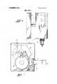
- FIG. 1is a front elevation view of a preferred form of injection apparatus constructed in accordance with this invention
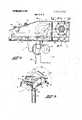
- FIG. 2is a fragmentary transverse section through the control cabinet and syringe assembly of the apparatus of FIG. 1, taken on the plane of the line 2-2 thereof;
- FIG. 3is a fragmentary isometric view on a somewhat reduced scale of the control cabinet and syringe assembly illustrating the range of movements of the syringe assembly relative to the control cabinet;
- FIG. 4is a top plan view of the syringe assembly of FIG. 2 as seen from the plane of the line 4-4 thereof;
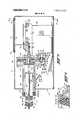
- FIG. 5is a fragmentary enlarged longitudinal section through the syringe assembly of FIG. 2, taken on the plane of the line 5-5;
- FIG. 6is an enlarged sectional view of the syringe piston seal of FIG. 5;
- FIG. 7is a fragmentary transverse section through the syringe assembly of FIG. 5 taken on the plane of the line '7-7;
- FIG. 8is a schematic diagram showing a control circuit for controlling the operation of the injector apparatus of FIGS. 1 through 7;
- FIG. 9is a schematic diagram showing a ground fault interrupter circuit for providing protection against current leaks to ground.
- FIGS. 1 and 2there is shown a preferred form of injection apparatus 1 in accordance with this invention including a syringe assembly 2 and control assembly 3 for controlling the operation thereof in a manner to be subsequently described.
- the syringe assembly 2is desirably connected to the control assembly by an elongated tube 4 which extends from one side of the syringe assembly box 5 into the control cabinet 6 as clearly illustrated in FIG. 2.
- a support 7suitably attached to the base plate 8 and having an opening therethrough in which the tube 4 is slidably received, permitting both longitudinal and rotational movement of the syringe assembly 2 relative to the control assembly 3.
- a pair of spaced apart stop rods 9 paralleling the tube 4limitsthe extent to which the syringe assembly 2 may be rotated in either direction for all longitudinal adjusted positions of the syringe assembly, there being provided a stop screw 10 on the distal end of the tube 4 which engages one or the other of the stop rods 9 during rotation of the syringe assembly in opposite directions to limit such rotation and protect the wiring harness 11 leading from the control assembly to the syringe assembly through the hollow tube 4 against breakage.
- the stop screw 10also limits the maximum extent to which the syringe assembly 2 may be extended relative to the control assembly 3 by engagement with the fixed support 7.
- the disposition of the stop rods 9, only one of which is shown,is such that the syringe 12 of the syringe assembly 2 may be tilted a maximum of +1 50 and l50 from the vertical as illustrated in FIG. 3, and the syringe assembly may also be extended from 0 to approximately 18 inches from the control cabinet 6.
- a lock knob 16is provided on the control cabinet 6. Tightening of the lock knob 16 causes the tube 4 to be clamped by a flexible collar 17 on the stationary support 7, the lock knob being connected to the collar 17 by a threaded rod 18. Further adjustments of the position of the syringe assembly 2 will be permitted upon loosening the lock knob 16 and subsequently retightening the same after the syringe assembly has been moved to the desired adjusted position.
- control assembly 3may be mounted on a mobile support stand 19 with a triangular base 20 on which are mounted swivel casters 21 as shown in FIG. 1 to permit the unit to be wheeled about.
- Each caster 21desirably includes a separate lock 22 which when turned in one direction locks the caster against rotation and when turned in the opposite direction unlocks the caster.
- a column adjustment handle 23Adjacent the upper end of the stand column 19 may be provided a column adjustment handle 23 for raising and lowering of the control assembly 3 and syringe assembly 2 attached thereto.
- the height of the injector 1is desirably adjustable from approximately 38 to 57 inches by rotation of the column adjustment handle 23 in opposite directions, and a column lock nut 24 is desirably provided for locking the control assembly and syringe assembly in the desired vertical adjusted position.
- the syringe assembly 2includes a main support housing 28 to which is bolted a syringe housing 29 for receipt of the barrel 30 of the syringe 12.
- the syringe barrel 30has a radial outwardly projecting flange 31 intermediate the ends of the barrel for accurately locating and clamping the barrel within the syringe housing 29.
- Axially extending into the syringe barrel 30is a ball screw shaft 34 which has a push-pull screw 35 threaded into the forward end thereof to facilitate positive attachment of a syringe piston 36 to the ball screw shaft.
- the syringe piston 36is shown screwed onto a screw lock-on nut 37 which has a polygonal shaped recess 38 therein of a shape corresponding to but slightly larger than the head 39 of the push-pull screw 35 for receipt of such head within the recess.
- the enlarged recess 38 within the screw lock-on nut 37provides a radial clearance with the push-pull screw 35 to accommodate any misalignment between the syringe piston 36 and ball screw shaft 34 while still permitting positive pushing and pulling of the syringe piston within the syringe barrel 30 during axial inward and outward movement of the ball screw shaft.
- Making the nut recess 38 and screw head 39 of a corresponding polygonal shapealso permits unscrewing of the syringe piston assembly 36 from the ball screw shaft 34 for sterilization of the syringe piston assembly as described hereafter.
- the syringe pistonmay be provided with an annular external groove 41 containing a Teflon slipper seal 42, with an O-ring 43 between the slipper seal 42 and bottom of the groove 41 which acts as a spring for maintaining the slipper seal in sealing contact with the syringe barrel wall as clearly shown in FIG. 6.
- a see-through syringe cap 45Threadedly received in the outer end of the syringe barrel 30 is a see-through syringe cap 45 having a central longitudinal passage 46 therethrough permitting expulsion of the fluid from the syringe during longitudinal movement of the syringe piston 36 within the syringe barrel 30 in the direction of the syringe cap.
- An O-ring 47is confined between the syringe cap 46 and an internal shoulder 48 on the syringe barrel to provide a fluid seal therebetween.
- the inner end of the ball screw shaft 34is received in a longitudinally extending generally channel-shape raceway 49 in the main housing 28 and is retained against rotation by a pair of ball bearing assemblies 50 disposed on opposite sides of the screw shaft and connected thereto by a dowel pin 51 extending through the center of the ball screw shaft and ball bearings.
- ball bearings 50absorb any rotational forces applied to the ball screw shaft 34 and support the inner end of the ball screw shaft for axial movement in either direction along the raceway 49.
- Axial movement of the ball screw shaft 34is obtained by rotation of a ball screw nut 55 having threaded engagement with the ball screw shaft and driven by a gear 56 suitably journaled within a gear box 57 between the main support housing 28 and the syringe housing 29 which provides a cover for the gear box.
- Rotation of the main gear 56may be accurately controlled by an electric motor 58, preferably a DC motor, with suitable motor mounts 59 being provided for direct attachment of the motor 58 to the main support housing 28.
- a suitable clutch mechanism 60is desirably used to transmit power from the drive motor 58 to the main gear 56 to protect the motor against overload and the various other parts of the syringe against damage in the event that the syringe piston 36 bottoms out with the motor still running or limits the pressure build up within the syringe barrel 30 due to fluid blockage or other reason.
- the clutch mechanism 60may comprise a drive pinion 61 with driven clutch face 62 freely rotatable on the outer end of the motor shaft 63 and retained in place by a thrust washer 64 and screw 65 attached to the free end of the motor shaft.
- a clutch disc 66 keyed to the motor shaft 63 for rotation therewithis maintained in driving engagement with the driven clutch face 62 by a clutch spring 67 as long as the force required to transmit axial motion to the ball screw shaft 34 and syringe piston 36 does not exceed a predetermined level.
- the clutch spring 67is confined between the clutch disc 66 and a clutch spring retainer 68 retained on the motor shaft by a snap ring 69 or the like.
- the axial location of the syringe piston 36 within the syringe barrel 30is indicated by a syringe piston position indicating rod 70 attached to the inner end of the ball screw shaft 34.
- the position indicating rod 70may be secured in place by a set screw 71 threaded into a recess in the inner end of the ball screw shaft.
- the sheet metal cover 5 which surrounds the syringe assembly 2has a longitudinally extending slot 72 in the top panel thereof for receipt of the upper end of the position indicator rod making it visible to the operator.
- a piston position indicator sight glass 73is shown covering the longitudinally extending slot 72 and retained in place by a pair of mounting brackets 74 suitably fastened to the cover 5 at opposite ends of the slot.
- the sight glass 73may have suitable indicia thereon and the sides of the longitudinal slot may have a calibrated scale to indicate the actual volume of contrast agent in the syringe 12 from to 120cc indicated by the position of the indicator rod 70 with respect to the calibrated scale.
- a pair of limit switches 75, 76 mounted in spaced apart relation on the main support housing 28 adjacent the raceway 49are engaged by the position indicator rod 70 when the syringe piston 36 reaches either end of its stroke to shut off the motor 58.
- the main support housing 28in addition to providing a gear box 57 and raceway 49 for the ball screw shaft 34 and support for the syringe drive motor 58 and limit switches 75, 76 therefor, also contains a recess 78 for receipt of one end of the tube 4 which connects the syringe assembly 2 to the control assembly 3.
- the connecting tube 4is retained in place within the recess 78 in the main support housing 28 by a bolt 79.
- a mounting ring 80 surrounding the connecting tube 4is attached to the main support housing 28 by suitable fasteners to secure the sheet metal cover 5 to the main support housing.
- a weight 81is also suitably attached to the main support housing 28 or motor 58 to locate the center of gravity of the syringe assembly 2 closely adjacent the axis of the tube 4 to facilitate tilting of the syringe assembly to any desired position as previously described.
- a thermostatically controlled syringe blanket 85for heating the contrast media from room temperature to 96 to 100 F and maintaining such temperature within twenty minutes after filling the syringe and turning on the main power.
- Both the blanket and thermostat 85are desirably molded in rubber and insulated from the syringe 12.
- the syringeis also electrically insulated from the syringe housing 29 by the plastic spacers 33'previously described, and the injector apparatus 1 has a ground clip 86 which is connected to the ground pin on the power cord 87.
- a ground fault interrupter circuit to be later describedis also desirably provided to remove the power from the motor and controls and provide a signal or alarm whenever there is a current leakage to ground exceeding 0.5 milliamps.
- Both the main support housing 28 and syringe housing 29are desirably made of aluminum for reduced weight, whereas the syringe barrel 30 is desirably made of non-corrosive high strength material such as stainless steel.
- the see-through syringe cap 45is desirably made of polycarbonate and the syringe piston 36 of delrin, both autoclavable to 250 F for sterilization.
- the various parts of the syringe 12are disassembled to permit sterilization thereof.
- the syringe piston 36is desirably moved to the Occ position as indicated by the volume indicator rod 70. Then the large nut 32 holding the syringe to the syringe housing 29 may be removed to permit the seethrough syringe cap 45 and syringe barrel 30 to be pulled out of the syringe housing.
- the see-through syringe cap 45may be unscrewed from the syringe barrel 30 and the O-ring 47 removed, after which the syringe piston assembly 36 may be unscrewed from the ball screw shaft 34, leaving the cap seal 42, 43 on the syringe piston.
- the syringe piston 36is screwed back onto the ball screw shaft 34 and the syringe barrel 30 is pushed into place and retained therein by screwing the large nut 32 back on to firmly clamp the radial flange 31 on the syringe barrel in place adjacent the end of the syringe housing 29.
- the syringe piston 36is retracted until the indicator reading corresponds to the desired volume of contrast media with which the syringe is to be filled. Then the lock knob 16 on the control cabinet 6 is loosened to permit the syringe assembly 2 to be rotated until the syringe 12 is pointing vertically upward so that the contrast media may be poured directly into the syringe barrel, keeping the fluid level below the O-ring groove 48.
- the O-ring 47Before filling the syringe barrel, the O-ring 47 is inserted into the O-ring groove 48 and afterwards the see-through cap 45 is screwed into the barrel until it bottoms against the O-ring.
- one end of a cathetermay be connected to the luer loc fitting on the seethrough syringe cap 45 and the other end inserted into an empty contrast media bottle to permit the syringe piston 36 to be moved slightly forward to express any trapped air from the syringe or catheter.
- the lock knob 16is loosened and the syringe assembly 2 rotated until the tip of the syringe 12 is pointing down from the horizontal at a maximum angle from the horizontal of approximately 60.
- Suitable controlsare provided on the control panel 88 which permit selection of two different flow rates for two different periods of time. Separate control knobs are provided for selecting each rate of flow in cubic centimeters per second and the time of each flow rate in seconds.
- the first slow inject flow control knob 89permits a selection of a flow rate of anywhere from 0.3 to cc per second for a period of time anywhere from off to 25 seconds as determined by the setting of a second control knob or dial 90.
- the first rapid inject flow control knob 91permits the selection of a flow control rate of anywhere from 5 to 40cc per second for a period of time anywhere from off to 6 seconds as determined by still another control knob 92.
- the product of the flow rate and time for each of the slow and rapid inject phaseswill determine the volume of fluid injected during each phase of injection.
- An additional control knob 93may also be provided on the control panel 88 for selecting a delay period, for example, from 0 to 2 seconds after completion of the entire injection phase for triggering the X-ray exposure.
- An X-ray cable connector 94is shown for connecting the control box to an X-ray machine.
- a lighted on-off power switch 95which includes a amp circuit breaker, a manual loading and unloading switch 96, and a lighted armed/unarmed selector switch 97.
- the manual loading or unloading switch 96is used to fill or empty the syringe 12 when the armed/unarmed switch 97 is in the unarmed position.
- the unitmay be operated by a remote control or hand trigger switch 98 to inject contrast media into a patient either manually or automatically as described hereafter.
- a lighted safe/unsafe ground fault interrupter switch 99 and associated circuitdetects current leaks to ground above 0.5 milliamps, and automatically moves from the safe to unsafe position when the power switch 95 is on to remove power from the control and syringe assemblies.
- a ground fault interrupter push to test switch 100is also provided for checking the operation of the ground fault interrupter circuit. Correct operation of the ground fault interrupter circuit is indicated during a test when the unsafe light comes on and an audible alarm sounds. To turn the unsafe light off and stop the audible alarm after completion of a test merely requires pushing the safe/unsafe switch 99 to the safe position.
- the injector apparatus lWith the armed/unarmed switch 97 in the armed position, depressing and releasing the automatic position on the hand trigger switch 98 will cause the injector apparatus l to automatically sequentially inject the two different flow rates selected on the flow and rapid inject flow rate and time control dials 89, 90 and 91, 92, respectively.
- the injectionmay be stopped at any time during the automatic injection phase by depressing and releasing the manual position on the hand trigger switch 98.
- the entire injection phasewill remain under the direct control of the operator by pressing the manual position on the hand trigger switch. Releasing the manual position on the hand trigger switch at any time will immediately'stop the injection.
- the control assembly 3should first be raised to the desired height by loosening the stand lock knob 24 and rotating the stand adjustment handle 23 to raise or lower the control and syringe assemblies 3, 2 to the desired height, after which the lock knob may be tightened to hold such assemblies in the desired vertical adjusted position.
- the power cord 87should then be plugged into a suitable power source and the lighted main power switch turned on, followed by a testing of the ground fault interrupter circuit as previously described. If the ground fault interrupter circuit checks out properly, the safe- Iunsafe switch 99 should be pushed to the safe position to turn off the unsafe light and stop the audible alarm which should have gone on when the test switch was depressed to indicate a correct operation of the ground fault interrupter circuit.
- the load/unload switch 96should then be held in the unload position until the syringe piston 36 is at the Doc position to facilitate disassembly and sterilization of the syringe as previously described. After sterilization, the syringe piston 36 and syringe barrel 30 should be reassembled and with the armed/unarmed switch 97 in the unarmed position the load/unload switch 96 moved to the unload position to retract the syringe piston to the desired volume of contrast media as shown on the indicator rod 70.
- the cabinet lock knob 16should be loosened to permit the syringe assembly 2 to be rotated until the syringe 12 extends vertically upward and with O-ring 47 in place the contrast media may be poured into the syringe barrel, keeping the fluid level below the O-ring groove 48.
- the syringe cap 45should be threaded into position in the upper end of the syringe barrel 30.
- one end of a cathetermay be connected to the syringe cap 45 and the other end inserted into an empty contrast media bottle so that the unload switch 96 may be depressed to express any trapped air in the syringe or catheter.
- the cabinet lock knob 16should be loosened to permit the syringe 12 to be rotated until its tip is pointing down from the horizontal.
- the syringe assembly 2may also be extended horizontally from the control assembly 3 to the extent desired, followed by a tightening of the cabinet lock knob to lock the syringe in the desired position.
- both the slow inject control knobs 89 and 90 and rapid inject control knobs 91 and 92should be set to the desired flow rates and periods of time for each flow rate, and the X-ray delay control knob 93 should also be set to the desired time delay for the X-ray exposure after completion of the entire injection phase.
- the X-ray cable 94should also be properly connected both to the control assembly 3 and to the X-ray machine.
- the injector apparatus 1is now ready to be used to inject contrast media or other fluid into the patient after the catheter needle has been properly inserted.
- the injection phaseis under the control of the hand trigger switch 98 as soon as the armed/unarmed unarmed selector switch 97 is moved to the armed position, whereby movement of the hand trigger switch either to the automatic or manual positions will cause the contrast media to be injected into the patient.
- the hand trigger switch 98is depressed in the automatic direction, the switch may be released and the injector apparatus will still continue to inject the fluid into the patient in accordance with the programmed flow rates and times. However, such procedure may be interrupted at any time by depressing the hand trigger switch 98 in the manual direction and releasing it. Moving the hand trigger switch 98 in the manual direction requires the operator to continue to press the switch during manual injection since releasing the trigger switch after pushing it in the manual direction will immediately stop the injection.
- the X-ray machineOn completion of the injection, the X-ray machine will be automatically triggered after a time delay of from to 2 seconds as determined by the setting of the X-ray delay control knob 93. By then the earliest delivered contrast media has reached the digital vessels, while the final bolus is in the distal aorta with all vessels in between opacified.
- the X-ray sourceis desirably elevated maximally, preferably to six feet, and the X-ray film is positioned along the entire length under study, with appropriate filters.
- a single, long film holderis preferred, but multiple, overlapping film holders may also be used.
- FIG. 8is a schematic diagram of the primary control circuit 105 for controlling the operation of the injection apparatus 1 previously described. Included in the circuit is the circuit breaker and on-off switch 95 which must be depressed to energize the circuit. A light 106 signals that the power is on, and the circuit breaker 107 protects the circuit against an overload. The power to the circuit passes through a differential transformer 108 which produces a signal in the transformer core 109 whenever the current through the two coils 110, 111 is different, as when there is a current leakage to ground. This signal is picked up by the output coil 112 of a ground fault interrupter amplifier circuit 115, schematically illustrated in FIG.
- a ground fault interrupter circuit 115is desirably sufficiently sensitive to detect current leaks to ground above 0.5 milliamps.
- the ground fault interrupter test switch 100is connected to a suitable resistor 118 for simulating a current leakage when the test switch 100 is depressed to check the operation of the fault interrupter circuit 115. Correct operation of the ground fault interrupter circuit 115 is indicated when, upon pushing the test switch 100, the unsafe light 116 goes on and the buzzer or alarm 117 sounds.
- the operatorneed only depress the ground fault interrupter switch 99 to energize the relay R2 which opens the portion of the circuit including the unsafe light 116 and buzzer 117 causing them to be turned off.
- the armed/unarmed selector switch 97may be moved between the unarmed position shown in FIG. 6 in which operation of the syringe drive motor 58 may be manually controlled by the loading and unloading switch 96 and the armed position in which such motor may be controlled by the hand trigger switch 98.
- the hand trigger switch 98is taken out of the primary control circuit and the load- /unload switch 96 is in the circuit permitting manual operation of the syringe drive motor 58 in opposite directions by moving the load/unload switch to the load and unload positions for respectively filling or emptying the syringe 12.
- the relay R3When the load/unload switch 96 is moved to the unload position, the relay R3 is activated which closes the associated motor contacts C3 causing the motor to extend the syringe piston 36 for unloading the syringe. Movement of the load/unload switch 96 to the load position activates another relay R4 which closes its respective motor contacts C4 causing the direction of rotation of the motor 58 to be reversed to retract the syringe piston 36 for loading the syringe.
- the speed of the drive motor 58 when under the control of the load/unload switch 96is desirably greater during operation in the loading direction than in the unloading direction and is controlled by the amount of resistance in the SCR firing circuit.
- a field relay FR in the load/unload circuitactivates its associated contacts CF 1 when the load/unload switch is moved either to the load or unload positions to supply current to the motor field circuit.
- a manual relay MRswitches between the two motor speeds for loading and unloading the syringe.
- the manual relay MRWhen the switch 96 is moved to the unload position, the manual relay MR is energized, causing the associated contact CMl to be opened, whereby the speed of the motor 58 is controlled by the resistor for unloading the syringe, whereas when the switch 96 is moved to the load position, the manual relay MR is not energized, causing the associated contact CMl to be closed, whereby the speed of the motor is controlled by the resistor 126 for loading the syringe.
- resistors 125, 126may be used to control the speed of the motor during such modes.
- resistors 125, 126are selected so that when the load- /unload switch 96 is moved to the load position the syringe piston will be retracted to fill the syringe at a rate of approximately 6cc per second and when the switch 96 is moved to the unload position the syringe will be extended to empty the syringe at a rate of approximately l.3cc per second.
- Separate limit switches 75 and 76are provided in the unload and load circuits, respectively, for opening their respective contacts when the syringe piston 36 reaches the respective ends of its stroke.
- Movement of the armed/unarmed switch 97 to the armed positionremoves the load/unload switch 96 from the primary control circuit and readies the circuit for the injection phase through actuation of the hand trigger or remote control switch 98.
- the position of the armed/unarmed switch 97may readily be indicated by providing indicator lights 127 and 128 in the respective armed and unarmed circuits. Current is continuously supplied to the motor field windings when the injector apparatus is in the armed mode to avoid any time lag in building up the magnetic field during the normal injection phase, whereas during the unarmed mode, the motor field is only turned on when the field relay FR is energized by movement of the load/unload switch 96 to either of the load or unload positions.
- the hand trigger switch 98desirably includes both an automatic position 130 and an off/manual position 131.
- the relay R6is activated causing the associated contacts C6, C6 to close, and such contacts C6, C6 will remain closed even though the hand trigger switch 98 is released to cause automatic sequential injection of the fluid as determined by the settings of the slow and rapid inject control knobs 89, 90 and 91, 92.
- the injectionmay be stopped at any time during the automatic injection phase by moving the switch 98 to the off/manual position 131 and releasing the switch.
- the switch 98When the switch 98 is moved to the off/manual position, it activates the jog relay R7 which opens the contact C7 in the automatic control circuit, deenergizing the relay R6 and opening the associated contacts C6, C6 whereby when the switch 98 is then released, the injector motor will stop. Movement of the switch 98 -to the off or manual position also causes the jog relay R7 to close another contact C7 for manual operation of the injector during the armed mode. Releasing the switch 98 from the manual position will automatically stop the injection.
- a relay LRWhen the hand trigger switch 98 is moved either to the automatic or manual positions 130 or 131, a relay LR is energized which closes its associated contact CL for controlling the speed of the drive motor during slow injection as determined by the setting of the potentiometer control knob 89.
- a time delay relay T1is energized at the end of its timing cycle as set by the slow inject time potentiometer control knob 90 to open the contact CTl associated with the slow inject potentiometer control knob 89 and close the contact CTl associated with the rapid inject potentiometer control knob 91 for automatically switching from slow inject to rapid inject at the end of the slow inject time.
- the time delay relay Tlalso closes a switch CTl for actuating a second time delay relay T2 at the end of its timing as set by the rapid inject time control knob 92.
- the time delay relay T2When the time delay relay T2 is energized, it closes the contact CTZ for activating the X-ray time delay relay T3 after a delay of from to 2 seconds as set on the X-ray delay control knob 93. If the syringe piston 36 reaches the end of its stroke during the armed mode before the relay T3 is activated, the limit switch [32 will be tripped, stopping the drive motor 58 and activating the X-ray time delay relay T3 as previously described.
- the relay contacts C3, C4 on the motorprovide dynamic braking when both contacts are closed by creating a magnetic field which brakes the motor, as well known in the art.
- the method and apparatus of the present inventionminimize the time required for angiography of the extremities, reduce the amount of apparatus, and substantially contribute to more complete opacification and visualization.
- Such a method and apparatusalso make X-ray exposure minimal with fewer injections and smaller volumes of contrast media.
- the injector apparatusmay also be used for other arteriographic procedures as well, including conventional angiography, by using either the slow inject or rapid inject modes separately.
- the controls for the mode not usedare simply set at 60.
- control meansfurther comprises means for selectively stopping and restarting said piston at any time during such advancement.
- control meansfurther comprises switch means including an automatic position which when depressed and released causes said piston to automatically sequentially advance at such preselected rates of speed for such preselected periods of time, and an olT/manual position which when depressed and released stops such automatic advancement of said piston but continues such advancement as long as such off/manual position is depressed.
- control meansfurther comprises means for preselecting a time delay for actuation of an X-ray machine upon completion of such sequential advancement of said piston.
- control meansfurther comprises limit switch means for activating said time delay for such X-ray machine in the event that said piston reaches the end of its stroke before the preselected time.
- control meansfurther comprises an electric motor for driving said piston, and means for varying the speed of said electric motor to vary the speed of advancement of said piston in accordance with the preselected settings of said control means.
- control meansfurther comprises means for causing said motor to rotate in opposite directions to retract and extend said piston for respectively filling and emptying said syringe barrel.
- control meansfurther comprises means for causing said motor to rotate at a slower speed during extension of said piston for emptying said syringe barrel than during retraction of said piston for filling said syringe barrel.
- the apparatus of claim 6further comprising a ground fault interrupter circuit associated with said control means for detecting current leaks to ground and removing the power from said control means.
- control meansfurther comprises means for testing said ground fault interrupter circuit to check its operation.
- the apparatus of claim 13further comprising means for moving said piston at a faster rate for filling said syringe barrel than for emptying said syringe barrel.
- the apparatus of claim Ifurther comprising means for checking said syringe assembly for current leaks to ground prior to filling said syringe assembly with the desired quantity of fluid.
- the apparatus of claim 1further comprising a syringe cap and associated seal on the outer end of said syringe barrel.
- Injection apparatusfor injecting a fluid into the vascular system of a mammal comprising a syringe assembly including a syringe barrel containing a piston, means mounting said piston for axial movement within said syringe barrel for expelling said fluid therefrom, and control means for controlling the rate of speed of advance movement of said piston within said syringe barrel, said control means comprising means for independently preselecting more than one rate of speed of advance movement of said piston within said syringe barrel and volumes of each advancement prior to such advancement, and means for sequentially advancing said piston at such preselected rates of speed for such preselected volumes during such advancement of said piston.
- Injection apparatus for injecting a fluid into the vascular system of a mammalcomprising a syringe assembly including a syringe barrel containing a piston, and means mounting said piston for axial movement within said syringe barrel for expelling fluid therefrom, said last-mentioned means comprising a ball screw shaft connected to said piston, means mounting said ball screw shaft for axial movement but not rotational movement, a ball nut threadedly engaging said ball screw shaft, whereby rotation of said nut causes axial movement of said piston, and means for rotating said nut, said means mounting said ball screw shaft for axial movement but not rotational movement comprising a main support housing containing a longitudinally extending raceway for said ball screw shaft, said raceway being of generally channel shape, and a pair of ball bearing assemblies disposed on opposite sides of said ball screw shaft and connected thereto by a dowel pin extending through the center of said ball screw shaft and ball bearing assemblies, said ball bearing assemblies engaging said raceway to support said ball screw shaft for axial movement along
- the apparatus of claim 17further comprising means providing a positive push-pull connection between said piston and ball screw shaft while accommodating any axial misalignment therebetween.
- said lastmentioned meanscomprises a nut onto which said piston is threaded, said nut having a polygonal shaped recess therein, a push-pull screw attached to the outer end of said ball screw shaft, said screw having a head of a shape corresponding to the polygonal recess in said nut but slightly smaller than said recess for receipt therein with some radial clearance to accommodate any such misalignment between said piston and ball screw shaft while still permitting positive pushing and pulling of said piston during axial inward and outward movement of said ball screw shaft.
- Injection apparatusfor injecting a fluid into the vascular system of a mammal comprising a syringe assembly including a syringe barrel containing a piston, means mounting said piston for axial movement within said syringe barrel for expelling fluid therefrom, and a main support housing for said syringe assembly, said main support housing having an elongated tube projecting therefrom, and a control assembly for controlling the operation of said syringe assembly, said elongated tube extending into said control assembly, said control assembly including a support having an opening therethrough in which said tube is slidably received to permit both longitudinal and rotational movement of said syringe assembly relative to said control assembly, a pair of spaced apart stop rods mounted within said control assembly paralleling said tube adjacent opposite sides thereof, a stop screw on the distal end of said tube engageable with said stop rods to limit the rotation of said tube in opposite directions for all longitudinal adjusted positions of said syringe assembly relative to said control assembly, and means for clamping said
- said means for clamping said syringe assembly in the desired longitudinal and rotational adjusted positionscomprises a lock knob on said control assembly, a flexible collar surrounding said tube, and a rod extending from said lock knob and having threaded engagement with said collar for loosening and tightening said collar on said tube by rotation of said lock nut in opposite directions.
- the apparatus of claimfurther comprising a weight attached to said syringe assembly for locating the center of gravity of said syringe assembly closely adjacent the axis of rotation of said tube to facilitate rotation of the syringe assembly to any desired adjusted position.
- the apparatus of claim 20further comprising a support stand for said control assembly, and means mounting said control assembly on said support stand for vertical movement to provide for adjustment of the vertical height of the control assembly and syringe assembly connected thereto.
- said means for moving said piston axially within said syringe barrelincludes an electric motor for driving said piston, and clutch means for transmitting power from said motor to said piston to protect against damage if said piston bottoms out and limit pressure developed.
- the apparatus of claim 24further comprising a syringe housing surrounding said syringe barrel, means for releasably mounting said syringe barrel within said syringe housing, and means for electrically isolating said syringe barrel from said syringe housing.
- said syringe housingincludes a gear box containing drive mechanism for driving said piston by said motor, said syringe housing being attached to said main housing to provide a cover for said gear box.
Landscapes
- Health & Medical Sciences (AREA)
- Vascular Medicine (AREA)
- Engineering & Computer Science (AREA)
- Anesthesiology (AREA)
- Biomedical Technology (AREA)
- Heart & Thoracic Surgery (AREA)
- Hematology (AREA)
- Life Sciences & Earth Sciences (AREA)
- Animal Behavior & Ethology (AREA)
- General Health & Medical Sciences (AREA)
- Public Health (AREA)
- Veterinary Medicine (AREA)
- Infusion, Injection, And Reservoir Apparatuses (AREA)
- Apparatus For Radiation Diagnosis (AREA)
Abstract
Description
Claims (26)
Priority Applications (5)
| Application Number | Priority Date | Filing Date | Title |
|---|---|---|---|
| US00340226AUS3812843A (en) | 1973-03-12 | 1973-03-12 | Method and apparatus for injecting contrast media into the vascular system |
| US434847AUS3880138A (en) | 1973-03-12 | 1974-01-21 | Method for injecting contrast media into the vascular system |
| DE2410868ADE2410868A1 (en) | 1973-03-12 | 1974-03-07 | DEVICE AND METHOD FOR INJECTING CONTRAST AGENTS |
| FR7408185AFR2221157A1 (en) | 1973-03-12 | 1974-03-11 | |
| JP49027779AJPS5026487A (en) | 1973-03-12 | 1974-03-12 |
Applications Claiming Priority (1)
| Application Number | Priority Date | Filing Date | Title |
|---|---|---|---|
| US00340226AUS3812843A (en) | 1973-03-12 | 1973-03-12 | Method and apparatus for injecting contrast media into the vascular system |
Publications (1)
| Publication Number | Publication Date |
|---|---|
| US3812843Atrue US3812843A (en) | 1974-05-28 |
Family
ID=23332420
Family Applications (1)
| Application Number | Title | Priority Date | Filing Date |
|---|---|---|---|
| US00340226AExpired - LifetimeUS3812843A (en) | 1973-03-12 | 1973-03-12 | Method and apparatus for injecting contrast media into the vascular system |
Country Status (4)
| Country | Link |
|---|---|
| US (1) | US3812843A (en) |
| JP (1) | JPS5026487A (en) |
| DE (1) | DE2410868A1 (en) |
| FR (1) | FR2221157A1 (en) |
Cited By (184)
| Publication number | Priority date | Publication date | Assignee | Title |
|---|---|---|---|---|
| US3897888A (en)* | 1974-03-11 | 1975-08-05 | Toledo Stamping & Mfg | Metering apparatus for particulate material |
| US3912127A (en)* | 1974-10-29 | 1975-10-14 | Graco Inc | Precision metering system |
| US4006736A (en)* | 1974-11-27 | 1977-02-08 | Medrad, Inc. | Angiographic injector |
| US4154227A (en)* | 1977-10-11 | 1979-05-15 | Krause Horst E | Method and apparatus for pumping blood within a vessel |
| US4157716A (en)* | 1977-03-07 | 1979-06-12 | Contraves Ag | Apparatus for the dosed dispensing of a liquid |
| US4191187A (en)* | 1977-03-09 | 1980-03-04 | National Research Development Corporation | Medical apparatus |
| WO1980002366A1 (en)* | 1979-05-07 | 1980-11-13 | H Krause | Method and apparatus for pumping blood within a vessel |
| FR2518410A1 (en)* | 1981-12-21 | 1983-06-24 | Intermedicat Gmbh | PRESSURE INJECTION APPARATUS FOR OPERATING A SYRINGE |
| US4435173A (en) | 1982-03-05 | 1984-03-06 | Delta Medical Industries | Variable rate syringe pump for insulin delivery |
| US4452251A (en)* | 1982-11-05 | 1984-06-05 | Medrad, Inc. | Syringe content indicating device |
| US4465473A (en)* | 1981-11-24 | 1984-08-14 | Contraves Ag | Injection apparatus for the dosed delivery of a liquid |
| US4519258A (en)* | 1983-10-11 | 1985-05-28 | Eastman Kodak Company | Motorized pipette |
| US4585439A (en)* | 1983-09-07 | 1986-04-29 | Disetronic Ag. | Portable infusion unit |
| US4636198A (en)* | 1985-11-18 | 1987-01-13 | Mallinckrodt, Inc. | Power syringe with volume reducing adapter |
| US4648872A (en)* | 1983-11-15 | 1987-03-10 | Kamen Dean L | Volumetric pump with replaceable reservoir assembly |
| US4731058A (en)* | 1986-05-22 | 1988-03-15 | Pharmacia Deltec, Inc. | Drug delivery system |
| US4749109A (en)* | 1983-11-15 | 1988-06-07 | Kamen Dean L | Volumetric pump with replaceable reservoir assembly |
| US4854324A (en)* | 1984-01-31 | 1989-08-08 | Medrad, Inc. | Processor-controlled angiographic injector device |
| GB2229497A (en)* | 1989-03-10 | 1990-09-26 | Graseby Medical Ltd | Infusion pump safety device |
| US4973334A (en)* | 1987-01-16 | 1990-11-27 | Allo Pro Ag | Device for ejecting or taking in liquid or paste-like media |
| AU633406B2 (en)* | 1990-03-09 | 1993-01-28 | Angiodynamics, Inc. | Contrast media injector |
| US5279569A (en)* | 1991-06-07 | 1994-01-18 | Liebel-Flarsheim Company | Front loading apparatus for insecting fluid into animals |
| US5346470A (en)* | 1990-12-20 | 1994-09-13 | E-Z-Em, Inc. | Contrast media injector |
| US5354273A (en)* | 1992-12-14 | 1994-10-11 | Mallinckrodt Medical, Inc. | Delivery apparatus with pressure controlled delivery |
| US5368572A (en)* | 1993-01-06 | 1994-11-29 | Shirota Denki Rozai Kabushiki Kaisha | Injection device for dental anesthetic or like |
| US5494036A (en)* | 1993-11-26 | 1996-02-27 | Medrad, Inc. | Patient infusion system for use with MRI |
| USD391638S (en) | 1996-11-22 | 1998-03-03 | Liebel-Flarsheim Company | Electronically controlled contrast media injector for medical diagnostic imaging |
| USD392388S (en) | 1996-11-26 | 1998-03-17 | Liebel-Flarsheim Company | Electronically controlled contrast media injector for medical diagnostic imaging |
| US5739508A (en)* | 1994-07-12 | 1998-04-14 | Medrad, Inc. | Closed loop information path for medical fluid delivery systems |
| US5806519A (en)* | 1993-10-28 | 1998-09-15 | Medrad, Inc. | Total system for contrast delivery |
| US5840026A (en)* | 1994-09-21 | 1998-11-24 | Medrad, Inc. | Patient specific dosing contrast delivery systems and methods |
| WO1998052478A1 (en)* | 1997-05-19 | 1998-11-26 | Angiosonics, Inc. | Cooling system for ultrasound device |
| US5843037A (en)* | 1993-10-28 | 1998-12-01 | Medrad Inc. | Multipatient fluid dispensing |
| FR2770136A1 (en)* | 1997-10-27 | 1999-04-30 | Njc Innovations | Motorized syringe for administering therapeutic substances |
| US5925018A (en)* | 1994-11-14 | 1999-07-20 | Cma/Microdialysis Ab | Infusion and microdialysis pump |
| US5950619A (en)* | 1995-03-14 | 1999-09-14 | Siemens Aktiengesellschaft | Ultrasonic atomizer device with removable precision dosating unit |
| US5970974A (en)* | 1995-03-14 | 1999-10-26 | Siemens Aktiengesellschaft | Dosating unit for an ultrasonic atomizer device |
| WO2000015280A1 (en)* | 1998-09-15 | 2000-03-23 | Njc Innovations | Devices with power-driven syringe for administering therapeutic substances |
| WO2001097901A2 (en) | 2000-06-22 | 2001-12-27 | The Research Foundation Of The State University Of New York At Buffalo | Micro-injection pump |
| US6402718B1 (en)* | 1992-08-17 | 2002-06-11 | Medrad, Inc. | Front-loading medical injector and syringe for use therewith |
| US20020117668A1 (en)* | 1999-11-30 | 2002-08-29 | Jong-Sung Kim | X-ray image sensor and method for fabricating the same |
| US20020123716A1 (en)* | 2001-03-01 | 2002-09-05 | Vandiver Mark H. | Fluid injection system for coronary intervention |
| US6475192B1 (en) | 1992-08-17 | 2002-11-05 | Medrad, Inc. | System and method for providing information from a syringe to an injector |
| US20020165491A1 (en)* | 1999-11-24 | 2002-11-07 | Reilly David M. | Injectors, injector systems, syringes and methods of connecting a syringe to an injector |
| US20020198496A1 (en)* | 1995-04-20 | 2002-12-26 | Duchon Douglas J. | System and method for multiple injection procedures on heart vessels |
| US20030028145A1 (en)* | 1995-04-20 | 2003-02-06 | Duchon Douglas J. | Angiographic injector system with multiple processor redundancy |
| WO2003024504A3 (en)* | 2001-09-19 | 2003-07-17 | Insulet Corp | Plunger for patient infusion device |
| US20030169234A1 (en)* | 2002-03-05 | 2003-09-11 | Kempisty Mark S. | Remote control system including an on-screen display (OSD) |
| US6652489B2 (en) | 2000-02-07 | 2003-11-25 | Medrad, Inc. | Front-loading medical injector and syringes, syringe interfaces, syringe adapters and syringe plungers for use therewith |
| US6656158B2 (en) | 2002-04-23 | 2003-12-02 | Insulet Corporation | Dispenser for patient infusion device |
| US6656159B2 (en) | 2002-04-23 | 2003-12-02 | Insulet Corporation | Dispenser for patient infusion device |
| US6669669B2 (en) | 2001-10-12 | 2003-12-30 | Insulet Corporation | Laminated patient infusion device |
| US20040015124A1 (en)* | 1999-11-24 | 2004-01-22 | Sciulli Francis J. | Fluid delivery system having a syringe interface module separate from but in communicaiton with a control unit |
| US20040030233A1 (en)* | 2000-06-02 | 2004-02-12 | Frazier Michael G. | Communication systems for use with magnetic resonance imaging systems |
| US20040027083A1 (en)* | 2002-04-26 | 2004-02-12 | Toyoda Koki Kabushiki Kaisha | Motor control device |
| US6692457B2 (en) | 2002-03-01 | 2004-02-17 | Insulet Corporation | Flow condition sensor assembly for patient infusion device |
| US6699218B2 (en) | 2000-11-09 | 2004-03-02 | Insulet Corporation | Transcutaneous delivery means |
| US20040049161A1 (en)* | 1999-02-09 | 2004-03-11 | Shearn James G. J. | Directly engaged syringe driver system |
| US20040064041A1 (en)* | 2002-05-30 | 2004-04-01 | Lazzaro Frank A. | Front-loading medical injector and syringes, syringe interfaces, syringe adapters and syringe plungers for use therewith |
| US20040064096A1 (en)* | 2002-09-30 | 2004-04-01 | Flaherty J. Christopher | Components and methods for patient infusion device |
| US20040064088A1 (en)* | 2002-09-30 | 2004-04-01 | William Gorman | Dispenser components and methods for patient infusion device |
| US6723072B2 (en) | 2002-06-06 | 2004-04-20 | Insulet Corporation | Plunger assembly for patient infusion device |
| US20040078028A1 (en)* | 2001-11-09 | 2004-04-22 | Flaherty J. Christopher | Plunger assembly for patient infusion device |
| US6726650B2 (en)* | 1997-12-04 | 2004-04-27 | Bracco Research S.A. | Automatic liquid injection system and method |
| US6740059B2 (en) | 2000-09-08 | 2004-05-25 | Insulet Corporation | Devices, systems and methods for patient infusion |
| US6749587B2 (en) | 2001-02-22 | 2004-06-15 | Insulet Corporation | Modular infusion device and method |
| US20040116866A1 (en)* | 2002-12-17 | 2004-06-17 | William Gorman | Skin attachment apparatus and method for patient infusion device |
| US6768425B2 (en) | 2000-12-21 | 2004-07-27 | Insulet Corporation | Medical apparatus remote control and method |
| US20040153032A1 (en)* | 2002-04-23 | 2004-08-05 | Garribotto John T. | Dispenser for patient infusion device |
| US6830558B2 (en) | 2002-03-01 | 2004-12-14 | Insulet Corporation | Flow condition sensor assembly for patient infusion device |
| US20050038386A1 (en)* | 2002-08-02 | 2005-02-17 | Mallinckrodt Inc. | Injector |
| US20050065760A1 (en)* | 2003-09-23 | 2005-03-24 | Robert Murtfeldt | Method for advising patients concerning doses of insulin |
| US20050070847A1 (en)* | 2003-09-29 | 2005-03-31 | Van Erp Wilhelmus Petrus Martinus Maria | Rapid-exchange balloon catheter with hypotube shaft |
| US20050182366A1 (en)* | 2003-04-18 | 2005-08-18 | Insulet Corporation | Method For Visual Output Verification |
| US20050238507A1 (en)* | 2002-04-23 | 2005-10-27 | Insulet Corporation | Fluid delivery device |
| US6960192B1 (en) | 2002-04-23 | 2005-11-01 | Insulet Corporation | Transcutaneous fluid delivery system |
| US20060041229A1 (en)* | 2002-07-16 | 2006-02-23 | Insulet Corporation | Flow restriction system and method for patient infusion device |
| US7008535B1 (en) | 2000-08-04 | 2006-03-07 | Wayne State University | Apparatus for oxygenating wastewater |
| US20060178633A1 (en)* | 2005-02-03 | 2006-08-10 | Insulet Corporation | Chassis for fluid delivery device |
| US20060288125A1 (en)* | 2005-05-23 | 2006-12-21 | Boyd William T | System and method for user space operations for direct I/O between an application instance and an I/O adapter |
| US20070213662A1 (en)* | 2004-11-24 | 2007-09-13 | Medrad, Inc. | System And Apparatus For Modeling Pressures Generated During An Injection Procedure |
| US20070255135A1 (en)* | 2004-11-16 | 2007-11-01 | Medrad, Inc. | Systems and methods of modeling pharmaceutical propagation in a patient |
| EP1920718A1 (en)* | 1995-04-20 | 2008-05-14 | ACIST Medical Systems, Inc. | Radiographic contrast material injector |
| US7419478B1 (en) | 2003-06-25 | 2008-09-02 | Medrad, Inc. | Front-loading syringe for medical injector having a flexible syringe retaining ring |
| US20080221513A1 (en)* | 2005-02-21 | 2008-09-11 | Novo Nordisk A/S | Method for Ensuring Constant Speed of a Motor in an Injection Device |
| US20090043239A1 (en)* | 2005-05-27 | 2009-02-12 | Alfred Gagel | Device and method for transporting medicinal liquids |
| US20090226867A1 (en)* | 2008-03-04 | 2009-09-10 | Medrad, Inc. | Dynamic anthropomorphic cardiovascular phantom |
| US20090316970A1 (en)* | 2008-06-24 | 2009-12-24 | Medrad, Inc. | Identification of regions of interest and extraction of time value curves in imaging procedures |
| US20100030073A1 (en)* | 2006-12-29 | 2010-02-04 | Medrad, Inc. | Modeling of pharmaceutical propagation |
| US20100114064A1 (en)* | 2008-11-03 | 2010-05-06 | Medrad, Inc. | Mitigation of contrast-induced nephropathy |
| US20100113887A1 (en)* | 2006-12-29 | 2010-05-06 | Medrad, Inc. | Patient-based parameter generation systems for medical injection procedures |
| US20100174175A1 (en)* | 1995-04-12 | 2010-07-08 | Prince Martin R | Method and apparatus for imaging abdominal aorta and aortic aneurysms |
| US20100204574A1 (en)* | 1995-04-20 | 2010-08-12 | Duchon Douglas J | System and method for multiple injection procedures on heart vessels |
| US20100204572A1 (en)* | 2007-07-17 | 2010-08-12 | Medrad, Inc. | Devices, Systems and Methods for Determination of Parameters for a Procedure, for Estimation of Cardiopulmonary Function and for Fluid Delivery |
| US20140364830A1 (en)* | 2004-02-17 | 2014-12-11 | Mallinckrodt Llc | Injector auto purge |
| US9108047B2 (en) | 2010-06-04 | 2015-08-18 | Bayer Medical Care Inc. | System and method for planning and monitoring multi-dose radiopharmaceutical usage on radiopharmaceutical injectors |
| US20150265764A1 (en)* | 2013-01-16 | 2015-09-24 | H & B Electronic Gmbh & Co. Kg | Continuous infusion device |
| US9173995B1 (en) | 2014-10-28 | 2015-11-03 | Bayer Healthcare Llc | Self-orienting syringe and syringe interface |
| US9199033B1 (en) | 2014-10-28 | 2015-12-01 | Bayer Healthcare Llc | Self-orienting syringe and syringe interface |
| CN105999452A (en)* | 2016-04-22 | 2016-10-12 | 山东大学齐鲁医院 | Stoma enema auxiliary device |
| US9480797B1 (en) | 2015-10-28 | 2016-11-01 | Bayer Healthcare Llc | System and method for syringe plunger engagement with an injector |
| US9694131B2 (en) | 2003-11-25 | 2017-07-04 | Bayer Healthcare Llc | Medical injector system |
| US9700672B2 (en) | 2011-09-21 | 2017-07-11 | Bayer Healthcare Llc | Continuous multi-fluid pump device, drive and actuating system and method |
| US9744305B2 (en) | 2012-09-28 | 2017-08-29 | Bayer Healthcare Llc | Quick release plunger |
| US9844622B2 (en) | 2000-07-10 | 2017-12-19 | Bayer Healthcare Llc | Syringes for medical injector systems |
| US9855390B2 (en) | 2006-03-15 | 2018-01-02 | Bayer Healthcare Llc | Plunger covers and plungers for use in syringes |
| US9949704B2 (en) | 2012-05-14 | 2018-04-24 | Bayer Healthcare Llc | Systems and methods for determination of pharmaceutical fluid injection protocols based on x-ray tube voltage |
| US9959389B2 (en) | 2010-06-24 | 2018-05-01 | Bayer Healthcare Llc | Modeling of pharmaceutical propagation and parameter generation for injection protocols |
| US9956377B2 (en) | 2002-09-20 | 2018-05-01 | Angiodynamics, Inc. | Method and apparatus for intra-aortic substance delivery to a branch vessel |
| US10279112B2 (en) | 2012-09-24 | 2019-05-07 | Angiodynamics, Inc. | Power injector device and method of use |
| USD847985S1 (en) | 2007-03-14 | 2019-05-07 | Bayer Healthcare Llc | Syringe plunger cover |
| US10363342B2 (en) | 2016-02-04 | 2019-07-30 | Insulet Corporation | Anti-inflammatory cannula |
| US10507319B2 (en) | 2015-01-09 | 2019-12-17 | Bayer Healthcare Llc | Multiple fluid delivery system with multi-use disposable set and features thereof |
| US10777319B2 (en) | 2014-01-30 | 2020-09-15 | Insulet Netherlands B.V. | Therapeutic product delivery system and method of pairing |
| US10792418B2 (en) | 2014-10-28 | 2020-10-06 | Bayer Healthcare Llc | Self-orienting pressure jacket and pressure jacket-to-injector interface |
| US10806852B2 (en) | 2014-03-19 | 2020-10-20 | Bayer Healthcare Llc | System for syringe engagement to an injector |
| US10835674B2 (en) | 2015-11-13 | 2020-11-17 | Bayer Healthcare Llc | Nested syringe assembly |
| US10898638B2 (en) | 2016-03-03 | 2021-01-26 | Bayer Healthcare Llc | System and method for improved fluid delivery in multi-fluid injector systems |
| US10898656B2 (en) | 2017-09-26 | 2021-01-26 | Insulet Corporation | Needle mechanism module for drug delivery device |
| US11045603B2 (en) | 2017-02-22 | 2021-06-29 | Insulet Corporation | Needle insertion mechanisms for drug containers |
| US11090434B2 (en) | 2015-11-24 | 2021-08-17 | Insulet Corporation | Automated drug delivery system |
| US11129934B2 (en) | 2014-10-28 | 2021-09-28 | Bayer Healthcare Llc | Self-orienting pressure jacket and pressure jacket-to-injector interface |
| US11141535B2 (en) | 2017-08-31 | 2021-10-12 | Bayer Healthcare Llc | Fluid path impedance assessment for improving fluid delivery performance |
| US11147931B2 (en) | 2017-11-17 | 2021-10-19 | Insulet Corporation | Drug delivery device with air and backflow elimination |
| US11191893B2 (en) | 2018-01-31 | 2021-12-07 | Bayer Healthcare Llc | System and method for syringe engagement with injector |
| USD942005S1 (en) | 2007-03-14 | 2022-01-25 | Bayer Healthcare Llc | Orange syringe plunger cover |
| US11278853B2 (en) | 2013-03-13 | 2022-03-22 | Bayer Healthcare Llc | Method for controlling fluid accuracy and backflow compensation |
| US11324889B2 (en) | 2020-02-14 | 2022-05-10 | Insulet Corporation | Compensation for missing readings from a glucose monitor in an automated insulin delivery system |
| US11364341B2 (en) | 2015-11-25 | 2022-06-21 | Insulet Corporation | Wearable medication delivery device |
| US11369739B2 (en) | 2013-01-21 | 2022-06-28 | Medline Industries, Lp | Method to provide injection system parameters for injecting fluid into patient |
| US11439754B1 (en) | 2021-12-01 | 2022-09-13 | Insulet Corporation | Optimizing embedded formulations for drug delivery |
| US11478581B2 (en) | 2017-08-31 | 2022-10-25 | Bayer Healthcare Llc | Fluid injector system volume compensation system and method |
| US11551802B2 (en) | 2020-02-11 | 2023-01-10 | Insulet Corporation | Early meal detection and calorie intake detection |
| US11547800B2 (en) | 2020-02-12 | 2023-01-10 | Insulet Corporation | User parameter dependent cost function for personalized reduction of hypoglycemia and/or hyperglycemia in a closed loop artificial pancreas system |
| US11565039B2 (en) | 2018-10-11 | 2023-01-31 | Insulet Corporation | Event detection for drug delivery system |
| US11565043B2 (en) | 2018-05-04 | 2023-01-31 | Insulet Corporation | Safety constraints for a control algorithm based drug delivery system |
| US11598664B2 (en) | 2017-08-31 | 2023-03-07 | Bayer Healthcare Llc | Injector pressure calibration system and method |
| US11596740B2 (en) | 2015-02-18 | 2023-03-07 | Insulet Corporation | Fluid delivery and infusion devices, and methods of use thereof |
| US11607493B2 (en) | 2020-04-06 | 2023-03-21 | Insulet Corporation | Initial total daily insulin setting for user onboarding |
| US11628251B2 (en) | 2018-09-28 | 2023-04-18 | Insulet Corporation | Activity mode for artificial pancreas system |
| US11684713B2 (en) | 2012-03-30 | 2023-06-27 | Insulet Corporation | Fluid delivery device, transcutaneous access tool and insertion mechanism for use therewith |
| US11684716B2 (en) | 2020-07-31 | 2023-06-27 | Insulet Corporation | Techniques to reduce risk of occlusions in drug delivery systems |
| US11724027B2 (en) | 2016-09-23 | 2023-08-15 | Insulet Corporation | Fluid delivery device with sensor |
| US11738144B2 (en) | 2021-09-27 | 2023-08-29 | Insulet Corporation | Techniques enabling adaptation of parameters in aid systems by user input |
| US11779702B2 (en) | 2017-08-31 | 2023-10-10 | Bayer Healthcare Llc | Method for dynamic pressure control in a fluid injector system |
| US11786652B2 (en) | 2017-08-31 | 2023-10-17 | Bayer Healthcare Llc | System and method for drive member position and fluid injector system mechanical calibration |
| USD1002840S1 (en) | 2007-03-14 | 2023-10-24 | Bayer Healthcare Llc | Syringe plunger |
| US11801344B2 (en) | 2019-09-13 | 2023-10-31 | Insulet Corporation | Blood glucose rate of change modulation of meal and correction insulin bolus quantity |
| US11833329B2 (en) | 2019-12-20 | 2023-12-05 | Insulet Corporation | Techniques for improved automatic drug delivery performance using delivery tendencies from past delivery history and use patterns |
| US11857763B2 (en) | 2016-01-14 | 2024-01-02 | Insulet Corporation | Adjusting insulin delivery rates |
| US11865299B2 (en) | 2008-08-20 | 2024-01-09 | Insulet Corporation | Infusion pump systems and methods |
| US11883636B2 (en) | 2018-02-27 | 2024-01-30 | Bayer Healthcare Llc | Syringe plunger engagement mechanism |
| US11904140B2 (en) | 2021-03-10 | 2024-02-20 | Insulet Corporation | Adaptable asymmetric medicament cost component in a control system for medicament delivery |
| US11929158B2 (en) | 2016-01-13 | 2024-03-12 | Insulet Corporation | User interface for diabetes management system |
| US11935637B2 (en) | 2019-09-27 | 2024-03-19 | Insulet Corporation | Onboarding and total daily insulin adaptivity |
| USD1020794S1 (en) | 2018-04-02 | 2024-04-02 | Bigfoot Biomedical, Inc. | Medication delivery device with icons |
| US11957875B2 (en) | 2019-12-06 | 2024-04-16 | Insulet Corporation | Techniques and devices providing adaptivity and personalization in diabetes treatment |
| USD1024090S1 (en) | 2019-01-09 | 2024-04-23 | Bigfoot Biomedical, Inc. | Display screen or portion thereof with graphical user interface associated with insulin delivery |
| US11969579B2 (en) | 2017-01-13 | 2024-04-30 | Insulet Corporation | Insulin delivery methods, systems and devices |
| US11969582B2 (en) | 2017-01-06 | 2024-04-30 | Bayer Healthcare Llc | Syringe plunger with dynamic seal |
| US11986630B2 (en) | 2020-02-12 | 2024-05-21 | Insulet Corporation | Dual hormone delivery system for reducing impending hypoglycemia and/or hyperglycemia risk |
| US11998718B2 (en) | 2020-06-18 | 2024-06-04 | Bayer Healthcare Llc | System and method for syringe plunger engagement with an injector |
| USD1031029S1 (en) | 2003-11-25 | 2024-06-11 | Bayer Healthcare Llc | Syringe plunger |
| US12036389B2 (en) | 2020-01-06 | 2024-07-16 | Insulet Corporation | Prediction of meal and/or exercise events based on persistent residuals |
| US12042630B2 (en) | 2017-01-13 | 2024-07-23 | Insulet Corporation | System and method for adjusting insulin delivery |
| US12064591B2 (en) | 2013-07-19 | 2024-08-20 | Insulet Corporation | Infusion pump system and method |
| US12076160B2 (en) | 2016-12-12 | 2024-09-03 | Insulet Corporation | Alarms and alerts for medication delivery devices and systems |
| US12097355B2 (en) | 2023-01-06 | 2024-09-24 | Insulet Corporation | Automatically or manually initiated meal bolus delivery with subsequent automatic safety constraint relaxation |
| US12106837B2 (en) | 2016-01-14 | 2024-10-01 | Insulet Corporation | Occlusion resolution in medication delivery devices, systems, and methods |
| US12115351B2 (en) | 2020-09-30 | 2024-10-15 | Insulet Corporation | Secure wireless communications between a glucose monitor and other devices |
| US12121701B2 (en) | 2021-01-29 | 2024-10-22 | Insulet Corporation | Systems and methods for incorporating co-formulations of insulin in an automatic insulin delivery system |
| US12121700B2 (en) | 2020-07-22 | 2024-10-22 | Insulet Corporation | Open-loop insulin delivery basal parameters based on insulin delivery records |
| US12128215B2 (en) | 2020-09-30 | 2024-10-29 | Insulet Corporation | Drug delivery device with integrated optical-based glucose monitor |
| US12208239B2 (en) | 2018-08-28 | 2025-01-28 | Bayer Healthcare Llc | Fluid injector system, method of preventing fluid backflow, and computer program product |
| US12251544B2 (en) | 2018-04-19 | 2025-03-18 | Bayer Healthcare Llc | System and method for air detection in fluid injector |
| US12263326B2 (en) | 2016-11-14 | 2025-04-01 | Bayer Healthcare Llc | Methods and systems for verifying the contents of a syringe used for medical fluid delivery |
| US12318577B2 (en) | 2017-01-13 | 2025-06-03 | Insulet Corporation | System and method for adjusting insulin delivery |
| US12343502B2 (en) | 2017-01-13 | 2025-07-01 | Insulet Corporation | System and method for adjusting insulin delivery |
| US12370307B2 (en) | 2020-02-03 | 2025-07-29 | Insulet Corporation | Use of fuzzy logic in predicting user behavior affecting blood glucose concentration in a closed loop control system of an automated insulin delivery device |
| US12383166B2 (en) | 2016-05-23 | 2025-08-12 | Insulet Corporation | Insulin delivery system and methods with risk-based set points |
| US12406760B2 (en) | 2021-06-07 | 2025-09-02 | Insulet Corporation | Exercise safety prediction based on physiological conditions |
| US12427249B2 (en) | 2018-08-28 | 2025-09-30 | Bayer Healthcare Llc | Fluid injector system with improved ratio performance |
| US12431229B2 (en) | 2021-03-10 | 2025-09-30 | Insulet Corporation | Medicament delivery device with an adjustable and piecewise analyte level cost component to address persistent positive analyte level excursions |
| US12433512B2 (en) | 2020-12-18 | 2025-10-07 | Insulet Corporation | Adhesive pad with a metallic coil for securing an on-body medical device |
Families Citing this family (4)
| Publication number | Priority date | Publication date | Assignee | Title |
|---|---|---|---|---|
| DE19647701A1 (en)* | 1996-11-08 | 1998-05-14 | Schering Ag | Device for obtaining constant densities of contrast media in tissues and organs |
| DE19859811C2 (en)* | 1998-12-23 | 2001-05-10 | Hilekes Guido | Contrast agent injection system |
| DE202014001525U1 (en) | 2014-02-19 | 2014-03-27 | H & B Electronic Gmbh & Co. Kg | Continuous infusion device |
| CN104342568A (en)* | 2014-10-14 | 2015-02-11 | 杨雯雯 | Preparation method of elastic alloy |
Citations (11)
| Publication number | Priority date | Publication date | Assignee | Title |
|---|---|---|---|---|
| US2602446A (en)* | 1950-02-27 | 1952-07-08 | Antonina S Glass | Automatic medical injection apparatus |
| US2627270A (en)* | 1946-02-09 | 1953-02-03 | Antonina S Glass | Self-propelled automatic syringe |
| US3156236A (en)* | 1961-12-07 | 1964-11-10 | Cordis Corp | Medical injector |
| US3335724A (en)* | 1964-07-24 | 1967-08-15 | Erich M Gienapp | Remote control, repeating, variable stroke hypodermic syringe device |
| US3415419A (en)* | 1966-10-27 | 1968-12-10 | Jewett | Fluid administering system |
| US3456649A (en)* | 1965-12-03 | 1969-07-22 | Warren R Jewett | Motor driven fluid administration apparatus |
| US3523523A (en)* | 1966-06-30 | 1970-08-11 | Contraves Ag | Power driven medical injector syringe with electromagnetic coupling means |
| US3623474A (en)* | 1966-07-25 | 1971-11-30 | Medrad Inc | Angiographic injection equipment |
| US3631847A (en)* | 1966-03-04 | 1972-01-04 | James C Hobbs | Method and apparatus for injecting fluid into the vascular system |
| US3701345A (en)* | 1970-09-29 | 1972-10-31 | Medrad Inc | Angiographic injector equipment |
| US3720211A (en)* | 1971-08-18 | 1973-03-13 | G Kyrias | Automatic injection system |
- 1973
- 1973-03-12USUS00340226Apatent/US3812843A/ennot_activeExpired - Lifetime
- 1974
- 1974-03-07DEDE2410868Apatent/DE2410868A1/enactivePending
- 1974-03-11FRFR7408185Apatent/FR2221157A1/frnot_activeWithdrawn
- 1974-03-12JPJP49027779Apatent/JPS5026487A/jaactivePending
Patent Citations (11)
| Publication number | Priority date | Publication date | Assignee | Title |
|---|---|---|---|---|
| US2627270A (en)* | 1946-02-09 | 1953-02-03 | Antonina S Glass | Self-propelled automatic syringe |
| US2602446A (en)* | 1950-02-27 | 1952-07-08 | Antonina S Glass | Automatic medical injection apparatus |
| US3156236A (en)* | 1961-12-07 | 1964-11-10 | Cordis Corp | Medical injector |
| US3335724A (en)* | 1964-07-24 | 1967-08-15 | Erich M Gienapp | Remote control, repeating, variable stroke hypodermic syringe device |
| US3456649A (en)* | 1965-12-03 | 1969-07-22 | Warren R Jewett | Motor driven fluid administration apparatus |
| US3631847A (en)* | 1966-03-04 | 1972-01-04 | James C Hobbs | Method and apparatus for injecting fluid into the vascular system |
| US3523523A (en)* | 1966-06-30 | 1970-08-11 | Contraves Ag | Power driven medical injector syringe with electromagnetic coupling means |
| US3623474A (en)* | 1966-07-25 | 1971-11-30 | Medrad Inc | Angiographic injection equipment |
| US3415419A (en)* | 1966-10-27 | 1968-12-10 | Jewett | Fluid administering system |
| US3701345A (en)* | 1970-09-29 | 1972-10-31 | Medrad Inc | Angiographic injector equipment |
| US3720211A (en)* | 1971-08-18 | 1973-03-13 | G Kyrias | Automatic injection system |
Cited By (320)
| Publication number | Priority date | Publication date | Assignee | Title |
|---|---|---|---|---|
| US3897888A (en)* | 1974-03-11 | 1975-08-05 | Toledo Stamping & Mfg | Metering apparatus for particulate material |
| US3912127A (en)* | 1974-10-29 | 1975-10-14 | Graco Inc | Precision metering system |
| US4006736A (en)* | 1974-11-27 | 1977-02-08 | Medrad, Inc. | Angiographic injector |
| US4157716A (en)* | 1977-03-07 | 1979-06-12 | Contraves Ag | Apparatus for the dosed dispensing of a liquid |
| US4191187A (en)* | 1977-03-09 | 1980-03-04 | National Research Development Corporation | Medical apparatus |
| US4154227A (en)* | 1977-10-11 | 1979-05-15 | Krause Horst E | Method and apparatus for pumping blood within a vessel |
| WO1980002366A1 (en)* | 1979-05-07 | 1980-11-13 | H Krause | Method and apparatus for pumping blood within a vessel |
| US4465473A (en)* | 1981-11-24 | 1984-08-14 | Contraves Ag | Injection apparatus for the dosed delivery of a liquid |
| FR2518410A1 (en)* | 1981-12-21 | 1983-06-24 | Intermedicat Gmbh | PRESSURE INJECTION APPARATUS FOR OPERATING A SYRINGE |
| US4435173A (en) | 1982-03-05 | 1984-03-06 | Delta Medical Industries | Variable rate syringe pump for insulin delivery |
| US4452251A (en)* | 1982-11-05 | 1984-06-05 | Medrad, Inc. | Syringe content indicating device |
| US4585439A (en)* | 1983-09-07 | 1986-04-29 | Disetronic Ag. | Portable infusion unit |
| US4519258A (en)* | 1983-10-11 | 1985-05-28 | Eastman Kodak Company | Motorized pipette |
| US4648872A (en)* | 1983-11-15 | 1987-03-10 | Kamen Dean L | Volumetric pump with replaceable reservoir assembly |
| US4749109A (en)* | 1983-11-15 | 1988-06-07 | Kamen Dean L | Volumetric pump with replaceable reservoir assembly |
| US4854324A (en)* | 1984-01-31 | 1989-08-08 | Medrad, Inc. | Processor-controlled angiographic injector device |
| US4636198A (en)* | 1985-11-18 | 1987-01-13 | Mallinckrodt, Inc. | Power syringe with volume reducing adapter |
| US4705509A (en)* | 1985-11-18 | 1987-11-10 | Mallinckrodt, Inc. | Power syringe with volume reducing adapter |
| US4731058A (en)* | 1986-05-22 | 1988-03-15 | Pharmacia Deltec, Inc. | Drug delivery system |
| US4973334A (en)* | 1987-01-16 | 1990-11-27 | Allo Pro Ag | Device for ejecting or taking in liquid or paste-like media |
| GB2229497A (en)* | 1989-03-10 | 1990-09-26 | Graseby Medical Ltd | Infusion pump safety device |
| GB2229497B (en)* | 1989-03-10 | 1992-06-03 | Graseby Medical Ltd | Infusion pump |
| AU633406B2 (en)* | 1990-03-09 | 1993-01-28 | Angiodynamics, Inc. | Contrast media injector |
| US5249579A (en)* | 1990-03-09 | 1993-10-05 | E-Z-Em, Inc. | Contrast media injector |
| US5346470A (en)* | 1990-12-20 | 1994-09-13 | E-Z-Em, Inc. | Contrast media injector |
| US5451211A (en)* | 1991-06-07 | 1995-09-19 | Liebel-Flarsheim Company | Disposable front loadable syringe for power injector for injecting fluid into animals |
| US5300031A (en)* | 1991-06-07 | 1994-04-05 | Liebel-Flarsheim Company | Apparatus for injecting fluid into animals and disposable front loadable syringe therefor |
| US20060264744A1 (en)* | 1991-06-07 | 2006-11-23 | Liebel-Flarsheim Company | Method and Apparatus for Injecting Fluid into Animals and Disposable Front Loadable Syringe Therefor |
| US7081104B2 (en) | 1991-06-07 | 2006-07-25 | Liebel-Flarsheim Company | Method and apparatus for injecting fluid into animals and disposable front loadable syringe therefor |
| US5738659A (en)* | 1991-06-07 | 1998-04-14 | Liebel-Flarsheim Company | Method of injecting fluid into animals |
| US5456670A (en)* | 1991-06-07 | 1995-10-10 | Liebel-Flarsheim Company | Power injector for injecting fluid into animals |
| US5456669A (en)* | 1991-06-07 | 1995-10-10 | Liebel-Flarsheim Company | Method of front loading an injector and injecting fluid into animals therewith |
| US6659979B2 (en) | 1991-06-07 | 2003-12-09 | Liebel Flarsheim Company | Method of injecting fluid into animals |
| EP0749757A3 (en)* | 1991-06-07 | 1997-05-07 | Liebel Flarsheim Co | Apparatus for injecting fluid into animals and disposable front loading syringe therefor |
| JP3324752B2 (en) | 1991-06-07 | 2002-09-17 | リーベル−フラーシャイム カンパニー | Method and apparatus for injecting fluids into animals and disposable front-loading syringes therefor |
| US5279569A (en)* | 1991-06-07 | 1994-01-18 | Liebel-Flarsheim Company | Front loading apparatus for insecting fluid into animals |
| US6475192B1 (en) | 1992-08-17 | 2002-11-05 | Medrad, Inc. | System and method for providing information from a syringe to an injector |
| US20050059932A1 (en)* | 1992-08-17 | 2005-03-17 | Reilly David M. | Injector system having a front loading pressure jacket assembly |
| US6562008B1 (en) | 1992-08-17 | 2003-05-13 | Medrad, Inc. | Front loading medical injector and syringe for use therewith |
| US6808513B2 (en) | 1992-08-17 | 2004-10-26 | Medrad, Inc. | Front loading medical injector and syringe for use therewith |
| US6733478B2 (en) | 1992-08-17 | 2004-05-11 | Medrad, Inc. | System and method for providing information from a syringe to an injector |
| US7081105B2 (en) | 1992-08-17 | 2006-07-25 | Medrad, Inc. | Injector system having a front loading pressure jacket assembly |
| US6402718B1 (en)* | 1992-08-17 | 2002-06-11 | Medrad, Inc. | Front-loading medical injector and syringe for use therewith |
| US5354273A (en)* | 1992-12-14 | 1994-10-11 | Mallinckrodt Medical, Inc. | Delivery apparatus with pressure controlled delivery |
| US5368572A (en)* | 1993-01-06 | 1994-11-29 | Shirota Denki Rozai Kabushiki Kaisha | Injection device for dental anesthetic or like |
| US6306117B1 (en) | 1993-10-28 | 2001-10-23 | Medrad, Inc. | Multi-patient fluid dispensing |
| US5885216A (en)* | 1993-10-28 | 1999-03-23 | Medrad, Inc. | Total system for contrast delivery |
| US6731971B2 (en) | 1993-10-28 | 2004-05-04 | Medrad, Inc. | Fluid delivery system including a reusable flow path and a per-patient disposable fluid path |
| US20040199075A1 (en)* | 1993-10-28 | 2004-10-07 | Medrad, Inc. | Total system for contrast delivery |
| US6149627A (en)* | 1993-10-28 | 2000-11-21 | Medrad, Inc. | Multi-patient fluid dispensing |
| US6901283B2 (en) | 1993-10-28 | 2005-05-31 | Medrad, Inc. | Adjusting a condition of a fluid medium to produce an image of a patient |
| US5806519A (en)* | 1993-10-28 | 1998-09-15 | Medrad, Inc. | Total system for contrast delivery |
| US5843037A (en)* | 1993-10-28 | 1998-12-01 | Medrad Inc. | Multipatient fluid dispensing |
| US7427281B2 (en) | 1993-10-28 | 2008-09-23 | Medrad, Inc. | Method of delivering fluid mixtures to multiple patients |
| US6442418B1 (en) | 1993-10-28 | 2002-08-27 | Medrad, Inc. | Total system for contrast delivery |
| US5494036A (en)* | 1993-11-26 | 1996-02-27 | Medrad, Inc. | Patient infusion system for use with MRI |
| USRE36648E (en)* | 1993-11-26 | 2000-04-11 | Medrad, Inc. | Patient infusion system for use with MRI |
| USRE37602E1 (en) | 1993-11-26 | 2002-03-26 | Medrad, Inc. | Patient infusion system for use with MRI |
| US5920054A (en)* | 1994-07-12 | 1999-07-06 | Medrad, Inc. | Closed loop information path for medical fluid delivery systems |
| US5739508A (en)* | 1994-07-12 | 1998-04-14 | Medrad, Inc. | Closed loop information path for medical fluid delivery systems |
| US6385483B1 (en) | 1994-09-21 | 2002-05-07 | Medrad, Inc. | Patient specific dosing contrast delivery systems and methods |
| US5840026A (en)* | 1994-09-21 | 1998-11-24 | Medrad, Inc. | Patient specific dosing contrast delivery systems and methods |
| US20080045834A1 (en)* | 1994-09-21 | 2008-02-21 | Medrad, Inc. | System and method for delivering fluids to a balloon catheter |
| US6889074B2 (en) | 1994-09-21 | 2005-05-03 | Medrad, Inc. | Patient specific dosing contrast delivery systems and methods |
| US7313431B2 (en) | 1994-09-21 | 2007-12-25 | Medrad, Inc. | System and method for inflating a balloon catheter and delivering fluid media to a patient |
| US20040162488A1 (en)* | 1994-09-21 | 2004-08-19 | Medrad, Inc. | Patient specific dosing contrast delivery systems and methods |
| US5925018A (en)* | 1994-11-14 | 1999-07-20 | Cma/Microdialysis Ab | Infusion and microdialysis pump |
| US5970974A (en)* | 1995-03-14 | 1999-10-26 | Siemens Aktiengesellschaft | Dosating unit for an ultrasonic atomizer device |
| US5950619A (en)* | 1995-03-14 | 1999-09-14 | Siemens Aktiengesellschaft | Ultrasonic atomizer device with removable precision dosating unit |
| US20100174175A1 (en)* | 1995-04-12 | 2010-07-08 | Prince Martin R | Method and apparatus for imaging abdominal aorta and aortic aneurysms |
| US8005530B2 (en)* | 1995-04-12 | 2011-08-23 | Prince Martin R | Method and apparatus for imaging abdominal aorta and aortic aneurysms |
| EP1920718A1 (en)* | 1995-04-20 | 2008-05-14 | ACIST Medical Systems, Inc. | Radiographic contrast material injector |
| US8082018B2 (en) | 1995-04-20 | 2011-12-20 | Acist Medical Systems, Inc. | System and method for multiple injection procedures on heart vessels |
| US20020198496A1 (en)* | 1995-04-20 | 2002-12-26 | Duchon Douglas J. | System and method for multiple injection procedures on heart vessels |
| US20100204574A1 (en)* | 1995-04-20 | 2010-08-12 | Duchon Douglas J | System and method for multiple injection procedures on heart vessels |
| US20030028145A1 (en)* | 1995-04-20 | 2003-02-06 | Duchon Douglas J. | Angiographic injector system with multiple processor redundancy |
| US7662124B2 (en) | 1995-04-20 | 2010-02-16 | Acist Medical Systems, Inc. | System and method for multiple injection procedures on heart vessels |
| US20080103437A1 (en)* | 1995-04-20 | 2008-05-01 | Acist Medical Systems, Inc. | Angiographic Injector System with Multiple Processor Redundancy |
| USD391638S (en) | 1996-11-22 | 1998-03-03 | Liebel-Flarsheim Company | Electronically controlled contrast media injector for medical diagnostic imaging |
| USD392388S (en) | 1996-11-26 | 1998-03-17 | Liebel-Flarsheim Company | Electronically controlled contrast media injector for medical diagnostic imaging |
| WO1998052478A1 (en)* | 1997-05-19 | 1998-11-26 | Angiosonics, Inc. | Cooling system for ultrasound device |
| FR2770136A1 (en)* | 1997-10-27 | 1999-04-30 | Njc Innovations | Motorized syringe for administering therapeutic substances |
| WO1999021597A1 (en)* | 1997-10-27 | 1999-05-06 | Njc Innovations | Device for administering therapeutic substances with power-operated syringe |
| US7534239B1 (en) | 1997-12-04 | 2009-05-19 | Bracco Research S.A. | Automatic liquid injection system and method |
| US6726650B2 (en)* | 1997-12-04 | 2004-04-27 | Bracco Research S.A. | Automatic liquid injection system and method |
| WO2000015280A1 (en)* | 1998-09-15 | 2000-03-23 | Njc Innovations | Devices with power-driven syringe for administering therapeutic substances |
| US7972306B2 (en) | 1999-02-09 | 2011-07-05 | Carefusion 303, Inc. | Directly engaged syringe driver system |
| US20040049161A1 (en)* | 1999-02-09 | 2004-03-11 | Shearn James G. J. | Directly engaged syringe driver system |
| US7338472B2 (en)* | 1999-02-09 | 2008-03-04 | Cardinal Health 303, Inc. | Directly engaged syringe driver system |
| US20080154203A1 (en)* | 1999-02-09 | 2008-06-26 | Cardinal Health 303, Inc. | Directly engaged syringe driver system |
| US6958053B1 (en) | 1999-11-24 | 2005-10-25 | Medrad, Inc. | Injector providing drive member advancement and engagement with syringe plunger, and method of connecting a syringe to an injector |
| US7465290B2 (en) | 1999-11-24 | 2008-12-16 | Medrad, Inc. | Injector system including an injector drive member that automatically advances and engages a syringe plunger |
| US7029459B2 (en) | 1999-11-24 | 2006-04-18 | Medrad, Inc. | Injector system including a powered loading device for connecting a syringe to an injector |
| US20020165491A1 (en)* | 1999-11-24 | 2002-11-07 | Reilly David M. | Injectors, injector systems, syringes and methods of connecting a syringe to an injector |
| US20040015124A1 (en)* | 1999-11-24 | 2004-01-22 | Sciulli Francis J. | Fluid delivery system having a syringe interface module separate from but in communicaiton with a control unit |
| US20040068223A1 (en)* | 1999-11-24 | 2004-04-08 | Reilly David M. | Injector system including an injector drive member that automatically advances and engages a syringe plunger |
| US20020117668A1 (en)* | 1999-11-30 | 2002-08-29 | Jong-Sung Kim | X-ray image sensor and method for fabricating the same |
| US9636452B2 (en) | 2000-02-07 | 2017-05-02 | Bayer Healthcare Llc | Front-loading medical injector adapted to releasably engage a syringe regardless of the orientation of the syringe with respect to the injector |
| US20040133153A1 (en)* | 2000-02-07 | 2004-07-08 | Mark Trocki | Syringe adapter for use with a medical injector and method for adapting an injector |
| US6652489B2 (en) | 2000-02-07 | 2003-11-25 | Medrad, Inc. | Front-loading medical injector and syringes, syringe interfaces, syringe adapters and syringe plungers for use therewith |
| US7540856B2 (en) | 2000-02-07 | 2009-06-02 | Medrad, Inc. | Front-loading medical injector adapted to releasably engage a syringe regardless of the orientation of the syringe with respect to the injector |
| US20040133161A1 (en)* | 2000-02-07 | 2004-07-08 | Mark Trocki | Front-loading syringe adapted to releasably engage a medical injector regardless of the orientation of the syringe with respect to the injector |
| US20040133162A1 (en)* | 2000-02-07 | 2004-07-08 | Mark Trocki | Front-loading medical injector adapted to releasably engage a syringe regardless of the orientation of the syringe with respect to the injector |
| US8721596B2 (en) | 2000-02-07 | 2014-05-13 | Bayer Medical Care Inc. | Front-loading syringe adapted to releasably engage a medical injector regardless of the orientation of the syringe with respect to the injector |
| US20040133183A1 (en)* | 2000-02-07 | 2004-07-08 | Mark Trocki | Method of preparing for a fluid injection procedure using a medical injector and a syringe |
| US6704592B1 (en) | 2000-06-02 | 2004-03-09 | Medrad, Inc. | Communication systems for use with magnetic resonance imaging systems |
| US7221159B2 (en) | 2000-06-02 | 2007-05-22 | Medrad, Inc. | Communication systems for use with magnetic resonance imaging systems |
| US7283860B2 (en) | 2000-06-02 | 2007-10-16 | Medrad, Inc. | Communication systems for use with magnetic resonance imaging systems |
| US20040030233A1 (en)* | 2000-06-02 | 2004-02-12 | Frazier Michael G. | Communication systems for use with magnetic resonance imaging systems |
| WO2001097901A2 (en) | 2000-06-22 | 2001-12-27 | The Research Foundation Of The State University Of New York At Buffalo | Micro-injection pump |
| US9844622B2 (en) | 2000-07-10 | 2017-12-19 | Bayer Healthcare Llc | Syringes for medical injector systems |
| US7294278B2 (en) | 2000-08-04 | 2007-11-13 | Wayne State University | Method for oxygenating wastewater |
| US7008535B1 (en) | 2000-08-04 | 2006-03-07 | Wayne State University | Apparatus for oxygenating wastewater |
| US20050171512A1 (en)* | 2000-09-08 | 2005-08-04 | Insulet Corporation | Devices, systems and methods for patient infusion |
| US7029455B2 (en) | 2000-09-08 | 2006-04-18 | Insulet Corporation | Devices, systems and methods for patient infusion |
| US6740059B2 (en) | 2000-09-08 | 2004-05-25 | Insulet Corporation | Devices, systems and methods for patient infusion |
| US7137964B2 (en) | 2000-09-08 | 2006-11-21 | Insulet Corporation | Devices, systems and methods for patient infusion |
| US6699218B2 (en) | 2000-11-09 | 2004-03-02 | Insulet Corporation | Transcutaneous delivery means |
| US6768425B2 (en) | 2000-12-21 | 2004-07-27 | Insulet Corporation | Medical apparatus remote control and method |
| US6749587B2 (en) | 2001-02-22 | 2004-06-15 | Insulet Corporation | Modular infusion device and method |
| US20020123716A1 (en)* | 2001-03-01 | 2002-09-05 | Vandiver Mark H. | Fluid injection system for coronary intervention |
| US7044933B2 (en) | 2001-03-01 | 2006-05-16 | Scimed Life Systems, Inc. | Fluid injection system for coronary intervention |
| WO2003024504A3 (en)* | 2001-09-19 | 2003-07-17 | Insulet Corp | Plunger for patient infusion device |
| US20050021005A1 (en)* | 2001-10-12 | 2005-01-27 | Flaherty J. Christopher | Laminated patient infusion device |
| US6669669B2 (en) | 2001-10-12 | 2003-12-30 | Insulet Corporation | Laminated patient infusion device |
| US20040078028A1 (en)* | 2001-11-09 | 2004-04-22 | Flaherty J. Christopher | Plunger assembly for patient infusion device |
| US20040127844A1 (en)* | 2002-03-01 | 2004-07-01 | Flaherty J. Christopher | Flow condition sensor assembly for patient infusion device |
| US6692457B2 (en) | 2002-03-01 | 2004-02-17 | Insulet Corporation | Flow condition sensor assembly for patient infusion device |
| US7887505B2 (en) | 2002-03-01 | 2011-02-15 | Insulet Corporation | Flow condition sensor assembly for patient infusion device |
| US6830558B2 (en) | 2002-03-01 | 2004-12-14 | Insulet Corporation | Flow condition sensor assembly for patient infusion device |
| US20030169234A1 (en)* | 2002-03-05 | 2003-09-11 | Kempisty Mark S. | Remote control system including an on-screen display (OSD) |
| US20040153032A1 (en)* | 2002-04-23 | 2004-08-05 | Garribotto John T. | Dispenser for patient infusion device |
| US6960192B1 (en) | 2002-04-23 | 2005-11-01 | Insulet Corporation | Transcutaneous fluid delivery system |
| US6656159B2 (en) | 2002-04-23 | 2003-12-02 | Insulet Corporation | Dispenser for patient infusion device |
| US20050238507A1 (en)* | 2002-04-23 | 2005-10-27 | Insulet Corporation | Fluid delivery device |
| US6656158B2 (en) | 2002-04-23 | 2003-12-02 | Insulet Corporation | Dispenser for patient infusion device |
| US7303549B2 (en) | 2002-04-23 | 2007-12-04 | Insulet Corporation | Transcutaneous fluid delivery system |
| US20040027083A1 (en)* | 2002-04-26 | 2004-02-12 | Toyoda Koki Kabushiki Kaisha | Motor control device |
| US8574200B2 (en) | 2002-05-30 | 2013-11-05 | Medrad, Inc. | Dual syringe injector system |
| US8133203B2 (en) | 2002-05-30 | 2012-03-13 | Medrad, Inc. | Method of injecting fluids from a dual syringe injector system |
| US7553294B2 (en) | 2002-05-30 | 2009-06-30 | Medrad, Inc. | Syringe plunger sensing mechanism for a medical injector |
| US20040064041A1 (en)* | 2002-05-30 | 2004-04-01 | Lazzaro Frank A. | Front-loading medical injector and syringes, syringe interfaces, syringe adapters and syringe plungers for use therewith |
| US20090312632A1 (en)* | 2002-05-30 | 2009-12-17 | Medrad, Inc. | Syringe plunger sensing mechanism for a medical injector |
| US6723072B2 (en) | 2002-06-06 | 2004-04-20 | Insulet Corporation | Plunger assembly for patient infusion device |
| US20060041229A1 (en)* | 2002-07-16 | 2006-02-23 | Insulet Corporation | Flow restriction system and method for patient infusion device |
| US7018360B2 (en) | 2002-07-16 | 2006-03-28 | Insulet Corporation | Flow restriction system and method for patient infusion device |
| US7854726B2 (en) | 2002-08-02 | 2010-12-21 | Liebel-Flarsheim Company | Injector |
| US7632246B2 (en)* | 2002-08-02 | 2009-12-15 | Liebel-Flarsheim Company | Injector |
| US20050038386A1 (en)* | 2002-08-02 | 2005-02-17 | Mallinckrodt Inc. | Injector |
| US8882704B2 (en) | 2002-08-02 | 2014-11-11 | Mallinckrodt Llc | Injector |
| US20090036771A1 (en)* | 2002-08-02 | 2009-02-05 | Liebel-Flarsheim Company | Injector |
| US20050038390A1 (en)* | 2002-08-02 | 2005-02-17 | Mallinckrodt Inc. | Injector |
| US20050038389A1 (en)* | 2002-08-02 | 2005-02-17 | Mallinckrodt Inc. | Injector |
| US20110184281A1 (en)* | 2002-08-02 | 2011-07-28 | Fago Frank M | Injector |
| US20070250005A1 (en)* | 2002-08-02 | 2007-10-25 | Mallinckrodt Inc. | Injector |
| US9956377B2 (en) | 2002-09-20 | 2018-05-01 | Angiodynamics, Inc. | Method and apparatus for intra-aortic substance delivery to a branch vessel |
| US20040064096A1 (en)* | 2002-09-30 | 2004-04-01 | Flaherty J. Christopher | Components and methods for patient infusion device |
| US20040064088A1 (en)* | 2002-09-30 | 2004-04-01 | William Gorman | Dispenser components and methods for patient infusion device |
| US7144384B2 (en) | 2002-09-30 | 2006-12-05 | Insulet Corporation | Dispenser components and methods for patient infusion device |
| US7128727B2 (en) | 2002-09-30 | 2006-10-31 | Flaherty J Christopher | Components and methods for patient infusion device |
| US20040116866A1 (en)* | 2002-12-17 | 2004-06-17 | William Gorman | Skin attachment apparatus and method for patient infusion device |
| US20050182366A1 (en)* | 2003-04-18 | 2005-08-18 | Insulet Corporation | Method For Visual Output Verification |
| US7419478B1 (en) | 2003-06-25 | 2008-09-02 | Medrad, Inc. | Front-loading syringe for medical injector having a flexible syringe retaining ring |
| US20050065760A1 (en)* | 2003-09-23 | 2005-03-24 | Robert Murtfeldt | Method for advising patients concerning doses of insulin |
| US20050070847A1 (en)* | 2003-09-29 | 2005-03-31 | Van Erp Wilhelmus Petrus Martinus Maria | Rapid-exchange balloon catheter with hypotube shaft |
| US9694131B2 (en) | 2003-11-25 | 2017-07-04 | Bayer Healthcare Llc | Medical injector system |
| US11596735B2 (en) | 2003-11-25 | 2023-03-07 | Bayer Healthcare Llc | Medical injector system |
| USD1031029S1 (en) | 2003-11-25 | 2024-06-11 | Bayer Healthcare Llc | Syringe plunger |
| US10434249B2 (en) | 2003-11-25 | 2019-10-08 | Bayer Healthcare Llc | Medical injector system |
| US10894124B2 (en) | 2003-11-25 | 2021-01-19 | Bayer Healthcare Llc | Medical injector system |
| US20140364830A1 (en)* | 2004-02-17 | 2014-12-11 | Mallinckrodt Llc | Injector auto purge |
| US20070255135A1 (en)* | 2004-11-16 | 2007-11-01 | Medrad, Inc. | Systems and methods of modeling pharmaceutical propagation in a patient |
| US8346342B2 (en) | 2004-11-16 | 2013-01-01 | Medrad, Inc. | Systems and methods of determining patient physiological parameters from an imaging procedure |
| US9616166B2 (en) | 2004-11-16 | 2017-04-11 | Bayer Healthcare Llc | Systems and methods of determining injection protocols for diagnostic imaging procedures |
| US20080097197A1 (en)* | 2004-11-16 | 2008-04-24 | Kalafut John F | Modeling of Pharmaceutical Propagation |
| US8197437B2 (en) | 2004-11-16 | 2012-06-12 | Medrad, Inc. | Systems and methods of modeling pharmaceutical propagation in a patient |
| US8295914B2 (en) | 2004-11-16 | 2012-10-23 | Medrad, Inc. | Systems and methods of determining patient transfer functions and modeling patient response to a pharmaceutical injection |
| US7925330B2 (en) | 2004-11-24 | 2011-04-12 | Medrad, Inc. | Devices, systems and methods for determining parameters of one or more phases of an injection procedure |
| US9238099B2 (en) | 2004-11-24 | 2016-01-19 | Bayer Healthcare Llc | System and apparatus for modeling pressures generated during an injection procedure |
| US20070282263A1 (en)* | 2004-11-24 | 2007-12-06 | Medrad, Inc. | Devices, systems and methods for determining parameters of one or more phases of an injection procedure |
| US9950107B2 (en) | 2004-11-24 | 2018-04-24 | Bayer Healthcare Llc | Systems and methods for managing workflow for injection procedures |
| US20070213662A1 (en)* | 2004-11-24 | 2007-09-13 | Medrad, Inc. | System And Apparatus For Modeling Pressures Generated During An Injection Procedure |
| US10166326B2 (en) | 2004-11-24 | 2019-01-01 | Bayer Healthcare Llc | Devices, systems and methods for determining parameters of one or more phases of an injection procedure |
| US20060178633A1 (en)* | 2005-02-03 | 2006-08-10 | Insulet Corporation | Chassis for fluid delivery device |
| US8382701B2 (en) | 2005-02-21 | 2013-02-26 | Novo Nordisk A/S | Method for ensuring constant speed of a motor in an injection device |
| US7993300B2 (en) | 2005-02-21 | 2011-08-09 | Novo Nordisk As | Method for ensuring constant speed of a motor in an injection device |
| US20080221513A1 (en)* | 2005-02-21 | 2008-09-11 | Novo Nordisk A/S | Method for Ensuring Constant Speed of a Motor in an Injection Device |
| US20060288125A1 (en)* | 2005-05-23 | 2006-12-21 | Boyd William T | System and method for user space operations for direct I/O between an application instance and an I/O adapter |
| US20090043239A1 (en)* | 2005-05-27 | 2009-02-12 | Alfred Gagel | Device and method for transporting medicinal liquids |
| US8430833B2 (en) | 2005-05-27 | 2013-04-30 | Fresenius Medical Care Deutschland Gmbh | Device and method for transporting medicinal liquids |
| US10668221B2 (en) | 2006-03-15 | 2020-06-02 | Bayer Healthcare Llc | Plunger covers and plungers for use in syringes |
| US9855390B2 (en) | 2006-03-15 | 2018-01-02 | Bayer Healthcare Llc | Plunger covers and plungers for use in syringes |
| US20100030073A1 (en)* | 2006-12-29 | 2010-02-04 | Medrad, Inc. | Modeling of pharmaceutical propagation |
| US10463782B2 (en) | 2006-12-29 | 2019-11-05 | Bayer Healthcare Llc | Patient-based parameter generation systems for medical injection procedures |
| US9302044B2 (en) | 2006-12-29 | 2016-04-05 | Bayer Healthcare Llc | Patient-based parameter generation systems for medical injection procedures |
| US20100113887A1 (en)* | 2006-12-29 | 2010-05-06 | Medrad, Inc. | Patient-based parameter generation systems for medical injection procedures |
| USD1030052S1 (en) | 2007-03-14 | 2024-06-04 | Bayer Healthcare Llc | Syringe plunger |
| USD847985S1 (en) | 2007-03-14 | 2019-05-07 | Bayer Healthcare Llc | Syringe plunger cover |
| USD942005S1 (en) | 2007-03-14 | 2022-01-25 | Bayer Healthcare Llc | Orange syringe plunger cover |
| USD1002840S1 (en) | 2007-03-14 | 2023-10-24 | Bayer Healthcare Llc | Syringe plunger |
| USD1030051S1 (en) | 2007-03-14 | 2024-06-04 | Bayer Healthcare Llc | Syringe plunger |
| US9008759B2 (en) | 2007-07-17 | 2015-04-14 | Bayer Medical Care Inc. | Devices and systems for determination of parameters for a procedure, for estimation of cardiopulmonary function and for fluid delivery |
| US8428694B2 (en) | 2007-07-17 | 2013-04-23 | Medrad, Inc. | Methods for determination of parameters for a procedure, for estimation of cardiopulmonary function and for fluid delivery |
| US20100204572A1 (en)* | 2007-07-17 | 2010-08-12 | Medrad, Inc. | Devices, Systems and Methods for Determination of Parameters for a Procedure, for Estimation of Cardiopulmonary Function and for Fluid Delivery |
| US20090226867A1 (en)* | 2008-03-04 | 2009-09-10 | Medrad, Inc. | Dynamic anthropomorphic cardiovascular phantom |
| US8608484B2 (en) | 2008-03-04 | 2013-12-17 | Medrad, Inc. | Dynamic anthropomorphic cardiovascular phantom |
| US20090316970A1 (en)* | 2008-06-24 | 2009-12-24 | Medrad, Inc. | Identification of regions of interest and extraction of time value curves in imaging procedures |
| US8699770B2 (en) | 2008-06-24 | 2014-04-15 | Bayer Medical Care Inc. | Identification of regions of interest and extraction of time value curves in imaging procedures |
| US8315449B2 (en) | 2008-06-24 | 2012-11-20 | Medrad, Inc. | Identification of regions of interest and extraction of time value curves in imaging procedures |
| US12296139B2 (en) | 2008-08-20 | 2025-05-13 | Insulet Corporation | Infusion pump systems and methods |
| US11865299B2 (en) | 2008-08-20 | 2024-01-09 | Insulet Corporation | Infusion pump systems and methods |
| US20100114064A1 (en)* | 2008-11-03 | 2010-05-06 | Medrad, Inc. | Mitigation of contrast-induced nephropathy |
| US9421330B2 (en) | 2008-11-03 | 2016-08-23 | Bayer Healthcare Llc | Mitigation of contrast-induced nephropathy |
| US9108047B2 (en) | 2010-06-04 | 2015-08-18 | Bayer Medical Care Inc. | System and method for planning and monitoring multi-dose radiopharmaceutical usage on radiopharmaceutical injectors |
| US9463335B2 (en) | 2010-06-04 | 2016-10-11 | Bayer Healthcare Llc | System and method for planning and monitoring multi-dose radiopharmaceutical usage on radiopharmaceutical injectors |
| US9959389B2 (en) | 2010-06-24 | 2018-05-01 | Bayer Healthcare Llc | Modeling of pharmaceutical propagation and parameter generation for injection protocols |
| US9700672B2 (en) | 2011-09-21 | 2017-07-11 | Bayer Healthcare Llc | Continuous multi-fluid pump device, drive and actuating system and method |
| US11684713B2 (en) | 2012-03-30 | 2023-06-27 | Insulet Corporation | Fluid delivery device, transcutaneous access tool and insertion mechanism for use therewith |
| US12329928B2 (en) | 2012-03-30 | 2025-06-17 | Insulet Corporation | Fluid delivery device, transcutaneous access tool and fluid drive mechanism for use therewith |
| US11191501B2 (en) | 2012-05-14 | 2021-12-07 | Bayer Healthcare Llc | Systems and methods for determination of pharmaceutical fluid injection protocols based on x-ray tube voltage |
| US9949704B2 (en) | 2012-05-14 | 2018-04-24 | Bayer Healthcare Llc | Systems and methods for determination of pharmaceutical fluid injection protocols based on x-ray tube voltage |
| US10279112B2 (en) | 2012-09-24 | 2019-05-07 | Angiodynamics, Inc. | Power injector device and method of use |
| US10286152B2 (en) | 2012-09-28 | 2019-05-14 | Bayer Healthcare Llc | Quick release plunger |
| US9744305B2 (en) | 2012-09-28 | 2017-08-29 | Bayer Healthcare Llc | Quick release plunger |
| US9579455B2 (en)* | 2013-01-16 | 2017-02-28 | H & B Electronic Gmbh & Co. Kg | Continuous infusion device |
| US20150265764A1 (en)* | 2013-01-16 | 2015-09-24 | H & B Electronic Gmbh & Co. Kg | Continuous infusion device |
| US11369739B2 (en) | 2013-01-21 | 2022-06-28 | Medline Industries, Lp | Method to provide injection system parameters for injecting fluid into patient |
| US11278853B2 (en) | 2013-03-13 | 2022-03-22 | Bayer Healthcare Llc | Method for controlling fluid accuracy and backflow compensation |
| US12064591B2 (en) | 2013-07-19 | 2024-08-20 | Insulet Corporation | Infusion pump system and method |
| US10777319B2 (en) | 2014-01-30 | 2020-09-15 | Insulet Netherlands B.V. | Therapeutic product delivery system and method of pairing |
| US11386996B2 (en) | 2014-01-30 | 2022-07-12 | Insulet Netherlands B.V. | Therapeutic product delivery system and method of pairing |
| US10806852B2 (en) | 2014-03-19 | 2020-10-20 | Bayer Healthcare Llc | System for syringe engagement to an injector |
| US11383029B2 (en) | 2014-03-19 | 2022-07-12 | Bayer Healthcare Llc | System for syringe engagement to an injector |
| US11103637B2 (en) | 2014-03-19 | 2021-08-31 | Bayer Healthcare Llc | System for syringe engagement to an injector |
| US11577022B2 (en) | 2014-10-28 | 2023-02-14 | Bayer Healthcare Llc | Self-orienting syringe and syringe interface |
| US11419977B2 (en) | 2014-10-28 | 2022-08-23 | Bayer Healthcare Llc | Self-orienting syringe and syringe interface |
| US10245375B2 (en) | 2014-10-28 | 2019-04-02 | Bayer Healthcare Llc | Self-orienting syringe and syringe interface |
| US9700670B2 (en) | 2014-10-28 | 2017-07-11 | Bayer Healthcare Llc | Self-orienting syringe and syringe interface |
| US11129934B2 (en) | 2014-10-28 | 2021-09-28 | Bayer Healthcare Llc | Self-orienting pressure jacket and pressure jacket-to-injector interface |
| US9173995B1 (en) | 2014-10-28 | 2015-11-03 | Bayer Healthcare Llc | Self-orienting syringe and syringe interface |
| US10512720B2 (en) | 2014-10-28 | 2019-12-24 | Bayer Healthcare Llc | Self-orienting syringe and syringe interface |
| US10792418B2 (en) | 2014-10-28 | 2020-10-06 | Bayer Healthcare Llc | Self-orienting pressure jacket and pressure jacket-to-injector interface |
| US9199033B1 (en) | 2014-10-28 | 2015-12-01 | Bayer Healthcare Llc | Self-orienting syringe and syringe interface |
| US10507319B2 (en) | 2015-01-09 | 2019-12-17 | Bayer Healthcare Llc | Multiple fluid delivery system with multi-use disposable set and features thereof |
| US11491318B2 (en) | 2015-01-09 | 2022-11-08 | Bayer Healthcare Llc | Multiple fluid delivery system with multi-use disposable set and features thereof |
| US11596740B2 (en) | 2015-02-18 | 2023-03-07 | Insulet Corporation | Fluid delivery and infusion devices, and methods of use thereof |
| US12102793B2 (en) | 2015-10-28 | 2024-10-01 | Bayer Healthcare Llc | System and method for syringe plunger engagement with an injector |
| US11547794B2 (en) | 2015-10-28 | 2023-01-10 | Bayer Healthcare Llc | System and method for syringe plunger engagement with an injector |
| US10512721B2 (en) | 2015-10-28 | 2019-12-24 | Bayer Healthcare Llc | System and method for syringe plunger engagement with an injector |
| US9480797B1 (en) | 2015-10-28 | 2016-11-01 | Bayer Healthcare Llc | System and method for syringe plunger engagement with an injector |
| US10835674B2 (en) | 2015-11-13 | 2020-11-17 | Bayer Healthcare Llc | Nested syringe assembly |
| US11744948B2 (en) | 2015-11-13 | 2023-09-05 | Bayer Healthcare Llc | Nested syringe assembly |
| US11090434B2 (en) | 2015-11-24 | 2021-08-17 | Insulet Corporation | Automated drug delivery system |
| US11744944B2 (en) | 2015-11-24 | 2023-09-05 | Insulet Corporation | Wearable automated medication delivery system |
| US11364341B2 (en) | 2015-11-25 | 2022-06-21 | Insulet Corporation | Wearable medication delivery device |
| US11929158B2 (en) | 2016-01-13 | 2024-03-12 | Insulet Corporation | User interface for diabetes management system |
| US12303668B2 (en) | 2016-01-14 | 2025-05-20 | Insulet Corporation | Adjusting insulin delivery rates |
| US12303667B2 (en) | 2016-01-14 | 2025-05-20 | Insulet Corporation | Adjusting insulin delivery rates |
| US12106837B2 (en) | 2016-01-14 | 2024-10-01 | Insulet Corporation | Occlusion resolution in medication delivery devices, systems, and methods |
| US11857763B2 (en) | 2016-01-14 | 2024-01-02 | Insulet Corporation | Adjusting insulin delivery rates |
| US10363342B2 (en) | 2016-02-04 | 2019-07-30 | Insulet Corporation | Anti-inflammatory cannula |
| US10898638B2 (en) | 2016-03-03 | 2021-01-26 | Bayer Healthcare Llc | System and method for improved fluid delivery in multi-fluid injector systems |
| US11672902B2 (en) | 2016-03-03 | 2023-06-13 | Bayer Healthcare Llc | System and method for improved fluid delivery in multi-fluid injector systems |
| CN105999452A (en)* | 2016-04-22 | 2016-10-12 | 山东大学齐鲁医院 | Stoma enema auxiliary device |
| US12383166B2 (en) | 2016-05-23 | 2025-08-12 | Insulet Corporation | Insulin delivery system and methods with risk-based set points |
| US11724027B2 (en) | 2016-09-23 | 2023-08-15 | Insulet Corporation | Fluid delivery device with sensor |
| US12263326B2 (en) | 2016-11-14 | 2025-04-01 | Bayer Healthcare Llc | Methods and systems for verifying the contents of a syringe used for medical fluid delivery |
| US12076160B2 (en) | 2016-12-12 | 2024-09-03 | Insulet Corporation | Alarms and alerts for medication delivery devices and systems |
| US11969582B2 (en) | 2017-01-06 | 2024-04-30 | Bayer Healthcare Llc | Syringe plunger with dynamic seal |
| US12161841B2 (en) | 2017-01-13 | 2024-12-10 | Insulet Corporation | Insulin delivery methods, systems and devices |
| US12318577B2 (en) | 2017-01-13 | 2025-06-03 | Insulet Corporation | System and method for adjusting insulin delivery |
| US11969579B2 (en) | 2017-01-13 | 2024-04-30 | Insulet Corporation | Insulin delivery methods, systems and devices |
| US12042630B2 (en) | 2017-01-13 | 2024-07-23 | Insulet Corporation | System and method for adjusting insulin delivery |
| US12343502B2 (en) | 2017-01-13 | 2025-07-01 | Insulet Corporation | System and method for adjusting insulin delivery |
| US11045603B2 (en) | 2017-02-22 | 2021-06-29 | Insulet Corporation | Needle insertion mechanisms for drug containers |
| US12214155B2 (en) | 2017-08-31 | 2025-02-04 | Bayer Healthcare Llc | Fluid injector system volume compensation system and method |
| US11141535B2 (en) | 2017-08-31 | 2021-10-12 | Bayer Healthcare Llc | Fluid path impedance assessment for improving fluid delivery performance |
| US11598664B2 (en) | 2017-08-31 | 2023-03-07 | Bayer Healthcare Llc | Injector pressure calibration system and method |
| US11786652B2 (en) | 2017-08-31 | 2023-10-17 | Bayer Healthcare Llc | System and method for drive member position and fluid injector system mechanical calibration |
| US11826553B2 (en) | 2017-08-31 | 2023-11-28 | Bayer Healthcare Llc | Fluid path impedance assessment for improving fluid delivery performance |
| US11779702B2 (en) | 2017-08-31 | 2023-10-10 | Bayer Healthcare Llc | Method for dynamic pressure control in a fluid injector system |
| US11478581B2 (en) | 2017-08-31 | 2022-10-25 | Bayer Healthcare Llc | Fluid injector system volume compensation system and method |
| US10898656B2 (en) | 2017-09-26 | 2021-01-26 | Insulet Corporation | Needle mechanism module for drug delivery device |
| US11147931B2 (en) | 2017-11-17 | 2021-10-19 | Insulet Corporation | Drug delivery device with air and backflow elimination |
| US11191893B2 (en) | 2018-01-31 | 2021-12-07 | Bayer Healthcare Llc | System and method for syringe engagement with injector |
| US11883636B2 (en) | 2018-02-27 | 2024-01-30 | Bayer Healthcare Llc | Syringe plunger engagement mechanism |
| USD1020794S1 (en) | 2018-04-02 | 2024-04-02 | Bigfoot Biomedical, Inc. | Medication delivery device with icons |
| US12251544B2 (en) | 2018-04-19 | 2025-03-18 | Bayer Healthcare Llc | System and method for air detection in fluid injector |
| US12090301B2 (en) | 2018-05-04 | 2024-09-17 | Insulet Corporation | Safety constraints for a control algorithm based drug delivery system |
| US11565043B2 (en) | 2018-05-04 | 2023-01-31 | Insulet Corporation | Safety constraints for a control algorithm based drug delivery system |
| US12427249B2 (en) | 2018-08-28 | 2025-09-30 | Bayer Healthcare Llc | Fluid injector system with improved ratio performance |
| US12208239B2 (en) | 2018-08-28 | 2025-01-28 | Bayer Healthcare Llc | Fluid injector system, method of preventing fluid backflow, and computer program product |
| US11628251B2 (en) | 2018-09-28 | 2023-04-18 | Insulet Corporation | Activity mode for artificial pancreas system |
| US11565039B2 (en) | 2018-10-11 | 2023-01-31 | Insulet Corporation | Event detection for drug delivery system |
| USD1024090S1 (en) | 2019-01-09 | 2024-04-23 | Bigfoot Biomedical, Inc. | Display screen or portion thereof with graphical user interface associated with insulin delivery |
| US11801344B2 (en) | 2019-09-13 | 2023-10-31 | Insulet Corporation | Blood glucose rate of change modulation of meal and correction insulin bolus quantity |
| US11935637B2 (en) | 2019-09-27 | 2024-03-19 | Insulet Corporation | Onboarding and total daily insulin adaptivity |
| US11957875B2 (en) | 2019-12-06 | 2024-04-16 | Insulet Corporation | Techniques and devices providing adaptivity and personalization in diabetes treatment |
| US11833329B2 (en) | 2019-12-20 | 2023-12-05 | Insulet Corporation | Techniques for improved automatic drug delivery performance using delivery tendencies from past delivery history and use patterns |
| US12036389B2 (en) | 2020-01-06 | 2024-07-16 | Insulet Corporation | Prediction of meal and/or exercise events based on persistent residuals |
| US12370307B2 (en) | 2020-02-03 | 2025-07-29 | Insulet Corporation | Use of fuzzy logic in predicting user behavior affecting blood glucose concentration in a closed loop control system of an automated insulin delivery device |
| US11551802B2 (en) | 2020-02-11 | 2023-01-10 | Insulet Corporation | Early meal detection and calorie intake detection |
| US11547800B2 (en) | 2020-02-12 | 2023-01-10 | Insulet Corporation | User parameter dependent cost function for personalized reduction of hypoglycemia and/or hyperglycemia in a closed loop artificial pancreas system |
| US11986630B2 (en) | 2020-02-12 | 2024-05-21 | Insulet Corporation | Dual hormone delivery system for reducing impending hypoglycemia and/or hyperglycemia risk |
| US11324889B2 (en) | 2020-02-14 | 2022-05-10 | Insulet Corporation | Compensation for missing readings from a glucose monitor in an automated insulin delivery system |
| US11607493B2 (en) | 2020-04-06 | 2023-03-21 | Insulet Corporation | Initial total daily insulin setting for user onboarding |
| US11998718B2 (en) | 2020-06-18 | 2024-06-04 | Bayer Healthcare Llc | System and method for syringe plunger engagement with an injector |
| US12121700B2 (en) | 2020-07-22 | 2024-10-22 | Insulet Corporation | Open-loop insulin delivery basal parameters based on insulin delivery records |
| US11684716B2 (en) | 2020-07-31 | 2023-06-27 | Insulet Corporation | Techniques to reduce risk of occlusions in drug delivery systems |
| US12128215B2 (en) | 2020-09-30 | 2024-10-29 | Insulet Corporation | Drug delivery device with integrated optical-based glucose monitor |
| US12115351B2 (en) | 2020-09-30 | 2024-10-15 | Insulet Corporation | Secure wireless communications between a glucose monitor and other devices |
| US12433512B2 (en) | 2020-12-18 | 2025-10-07 | Insulet Corporation | Adhesive pad with a metallic coil for securing an on-body medical device |
| US12121701B2 (en) | 2021-01-29 | 2024-10-22 | Insulet Corporation | Systems and methods for incorporating co-formulations of insulin in an automatic insulin delivery system |
| US11904140B2 (en) | 2021-03-10 | 2024-02-20 | Insulet Corporation | Adaptable asymmetric medicament cost component in a control system for medicament delivery |
| US12370309B2 (en) | 2021-03-10 | 2025-07-29 | Insulet Corporation | Adaptive update of automatic insulin delivery (AID) control parameters |
| US12431229B2 (en) | 2021-03-10 | 2025-09-30 | Insulet Corporation | Medicament delivery device with an adjustable and piecewise analyte level cost component to address persistent positive analyte level excursions |
| US12406760B2 (en) | 2021-06-07 | 2025-09-02 | Insulet Corporation | Exercise safety prediction based on physiological conditions |
| US11738144B2 (en) | 2021-09-27 | 2023-08-29 | Insulet Corporation | Techniques enabling adaptation of parameters in aid systems by user input |
| US11439754B1 (en) | 2021-12-01 | 2022-09-13 | Insulet Corporation | Optimizing embedded formulations for drug delivery |
| US12097355B2 (en) | 2023-01-06 | 2024-09-24 | Insulet Corporation | Automatically or manually initiated meal bolus delivery with subsequent automatic safety constraint relaxation |
Also Published As
| Publication number | Publication date |
|---|---|
| FR2221157A1 (en) | 1974-10-11 |
| DE2410868A1 (en) | 1974-09-19 |
| JPS5026487A (en) | 1975-03-19 |
Similar Documents
| Publication | Publication Date | Title |
|---|---|---|
| US3812843A (en) | Method and apparatus for injecting contrast media into the vascular system | |
| US3880138A (en) | Method for injecting contrast media into the vascular system | |
| US3631847A (en) | Method and apparatus for injecting fluid into the vascular system | |
| US4006736A (en) | Angiographic injector | |
| US3523523A (en) | Power driven medical injector syringe with electromagnetic coupling means | |
| EP1037682B1 (en) | Angiographic injector system with multiple processor redundancy | |
| US3752145A (en) | Method for preventing air embolism in a syringe for angiographic power injector | |
| US6673048B1 (en) | Pressure sleeve assembly | |
| US6099502A (en) | Dual port syringe | |
| US7662124B2 (en) | System and method for multiple injection procedures on heart vessels | |
| DE69630370T2 (en) | ANGIOGRAPHIC INJECTOR | |
| CN108339188B (en) | imaging device | |
| EP3474938A1 (en) | Appliance for conveying a catheter, light guide or cable in a controlled manner | |
| JPH04231966A (en) | Bubble detector | |
| JPH06319797A (en) | Automatic hydraulic pressure control system | |
| CA1135585A (en) | Constant feed device | |
| LT4835B (en) | PRIVATE COMPUTER-MANAGED MEDICAL OR SIMILAR DISTRIBUTION SYSTEM | |
| DE19825999A1 (en) | System for intracorporeal and intraluminal X-ray therapy | |
| CN111939378A (en) | High-pressure injection device and high-pressure injection system | |
| US4044764A (en) | Fluid infusion apparatus | |
| US3313291A (en) | Apparatus for the injection of radioopaque liquid in angiography | |
| EP0551416B1 (en) | Controlled pressure fluid delivery device | |
| Armin et al. | The artery of the denervated rabbit's ear as a sensitive pharmacological test object | |
| CN217645631U (en) | High-pressure injector with heating and heat-preserving functions | |
| US3584623A (en) | Cannulae-flushing means |
Legal Events
| Date | Code | Title | Description |
|---|---|---|---|
| STCF | Information on status: patent grant | Free format text:PATENTED FILE - (OLD CASE ADDED FOR FILE TRACKING PURPOSES) | |
| AS | Assignment | Owner name:BFM ACQUISITION CORP., 2040 EAST DYER ROAD, SANTA Free format text:SECURITY INTEREST;ASSIGNOR:BFM ROMEC CORPORATION;REEL/FRAME:004830/0589 Effective date:19871015 Owner name:WELLS FARGO BANK, N.A., Free format text:SECURITY INTEREST;ASSIGNOR:BFM ACQUISITION CORP.,;REEL/FRAME:004834/0242 Effective date:19871015 Owner name:WELLS FARGO BANK, N.A., Free format text:SECURITY INTEREST;ASSIGNOR:BFM ROMEC CORPORATION OF DELAWARE;REEL/FRAME:004837/0337 Effective date:19871015 Owner name:WELLS FARGO BANK, N.A., Free format text:SECURITY INTEREST;ASSIGNOR:BMF ROMEC CORPORATION OF DELAWARE;REEL/FRAME:004838/0054 Effective date:19871015 Owner name:WELLS FARGO BANK, N.A.,,STATELESS Free format text:SECURITY INTEREST;ASSIGNOR:BFM ROMEC CORPORATION OF DELAWARE;REEL/FRAME:004837/0337 Effective date:19871015 Owner name:WELLS FARGO BANK, N.A.,STATELESS Free format text:SECURITY INTEREST;ASSIGNOR:BMF ROMEC CORPORATION OF DELAWARE;REEL/FRAME:004838/0054 Effective date:19871015 Owner name:BFM ACQUISITION CORP.,CALIFORNIA Free format text:SECURITY INTEREST;ASSIGNOR:BFM ROMEC CORPORATION;REEL/FRAME:004830/0589 Effective date:19871015 Owner name:WELLS FARGO BANK, N.A.,STATELESS Free format text:SECURITY INTEREST;ASSIGNOR:BFM ACQUISITION CORP.,;REEL/FRAME:004834/0242 Effective date:19871015 | |
| AS | Assignment | Owner name:BFM ROMEC CORP., A DE CORP. Free format text:ASSIGNMENT OF ASSIGNORS INTEREST.;ASSIGNOR:LEAR SIEGLER, INC.;REEL/FRAME:004837/0837 Effective date:19871111 Owner name:BFM ROMEC CORP., A DE CORP.,DELAWARE Free format text:ASSIGNMENT OF ASSIGNORS INTEREST;ASSIGNOR:LEAR SIEGLER, INC.;REEL/FRAME:004837/0837 Effective date:19871111 | |
| AS | Assignment | Owner name:BFM AEROSPACE CORPORATION Free format text:SECURITY INTEREST;ASSIGNOR:BFM ROMEC CORPORATION;REEL/FRAME:004854/0900 Effective date:19871125 Owner name:BFM AEROSPACE CORPORATION,CALIFORNIA Free format text:SECURITY INTEREST;ASSIGNOR:BFM ROMEC CORPORATION;REEL/FRAME:004854/0900 Effective date:19871125 | |
| AS | Assignment | Owner name:LEAR ROMEC CORP., A CA CORP., CALIFORNIA Free format text:ASSIGNMENT OF ASSIGNORS INTEREST.;ASSIGNOR:BFM ROMEC CORP. OF DE.;REEL/FRAME:005043/0985 Effective date:19890403 |