US3807713A - Bottle containing fluid for inhalation therapy apparatus - Google Patents
Bottle containing fluid for inhalation therapy apparatusDownload PDFInfo
- Publication number
- US3807713A US3807713AUS00307460AUS30746072AUS3807713AUS 3807713 AUS3807713 AUS 3807713AUS 00307460 AUS00307460 AUS 00307460AUS 30746072 AUS30746072 AUS 30746072AUS 3807713 AUS3807713 AUS 3807713A
- Authority
- US
- United States
- Prior art keywords
- container
- bottle
- integral
- conduit
- chamber
- Prior art date
- Legal status (The legal status is an assumption and is not a legal conclusion. Google has not performed a legal analysis and makes no representation as to the accuracy of the status listed.)
- Expired - Lifetime
Links
- 239000012530fluidSubstances0.000titleclaimsdescription3
- 238000002664inhalation therapyMethods0.000titleabstractdescription7
- 229920001169thermoplasticPolymers0.000claimsdescription16
- 239000004416thermosoftening plasticSubstances0.000claimsdescription16
- 239000012815thermoplastic materialSubstances0.000claimsdescription12
- 238000007789sealingMethods0.000claimsdescription10
- 238000004891communicationMethods0.000claimsdescription4
- 230000000717retained effectEffects0.000claimsdescription2
- XLYOFNOQVPJJNP-UHFFFAOYSA-NwaterSubstancesOXLYOFNOQVPJJNP-UHFFFAOYSA-N0.000abstractdescription14
- QVGXLLKOCUKJST-UHFFFAOYSA-Natomic oxygenChemical compound[O]QVGXLLKOCUKJST-UHFFFAOYSA-N0.000abstractdescription12
- 239000001301oxygenSubstances0.000abstractdescription12
- 229910052760oxygenInorganic materials0.000abstractdescription12
- NJPPVKZQTLUDBO-UHFFFAOYSA-NnovaluronChemical compoundC1=C(Cl)C(OC(F)(F)C(OC(F)(F)F)F)=CC=C1NC(=O)NC(=O)C1=C(F)C=CC=C1FNJPPVKZQTLUDBO-UHFFFAOYSA-N0.000abstractdescription9
- 239000006199nebulizerSubstances0.000abstractdescription5
- 239000008225water for inhalationSubstances0.000abstractdescription2
- 238000007373indentationMethods0.000description11
- 210000002445nippleAnatomy0.000description8
- 239000007789gasSubstances0.000description4
- 238000000465mouldingMethods0.000description4
- -1polyethylenePolymers0.000description4
- 238000004519manufacturing processMethods0.000description3
- 239000004698PolyethyleneSubstances0.000description2
- 239000004743PolypropyleneSubstances0.000description2
- 238000001816coolingMethods0.000description2
- 238000007599dischargingMethods0.000description2
- 210000003811fingerAnatomy0.000description2
- 239000007788liquidSubstances0.000description2
- 238000000034methodMethods0.000description2
- 229920000573polyethylenePolymers0.000description2
- 229920001155polypropylenePolymers0.000description2
- 238000000889atomisationMethods0.000description1
- 230000015572biosynthetic processEffects0.000description1
- 238000010276constructionMethods0.000description1
- 239000011521glassSubstances0.000description1
- 238000001746injection mouldingMethods0.000description1
- 230000001788irregularEffects0.000description1
- 230000013011matingEffects0.000description1
- 239000002184metalSubstances0.000description1
- 239000003595mistSubstances0.000description1
- 238000006213oxygenation reactionMethods0.000description1
- 239000004033plasticSubstances0.000description1
- 229920003023plasticPolymers0.000description1
- 230000000241respiratory effectEffects0.000description1
- 239000007787solidSubstances0.000description1
- 239000008223sterile waterSubstances0.000description1
- 210000003813thumbAnatomy0.000description1
Images

Classifications
- A—HUMAN NECESSITIES
- A61—MEDICAL OR VETERINARY SCIENCE; HYGIENE
- A61M—DEVICES FOR INTRODUCING MEDIA INTO, OR ONTO, THE BODY; DEVICES FOR TRANSDUCING BODY MEDIA OR FOR TAKING MEDIA FROM THE BODY; DEVICES FOR PRODUCING OR ENDING SLEEP OR STUPOR
- A61M16/00—Devices for influencing the respiratory system of patients by gas treatment, e.g. ventilators; Tracheal tubes
- A61M16/10—Preparation of respiratory gases or vapours
- A61M16/14—Preparation of respiratory gases or vapours by mixing different fluids, one of them being in a liquid phase
- A61M16/16—Devices to humidify the respiration air
- A—HUMAN NECESSITIES
- A61—MEDICAL OR VETERINARY SCIENCE; HYGIENE
- A61M—DEVICES FOR INTRODUCING MEDIA INTO, OR ONTO, THE BODY; DEVICES FOR TRANSDUCING BODY MEDIA OR FOR TAKING MEDIA FROM THE BODY; DEVICES FOR PRODUCING OR ENDING SLEEP OR STUPOR
- A61M11/00—Sprayers or atomisers specially adapted for therapeutic purposes
- A61M11/06—Sprayers or atomisers specially adapted for therapeutic purposes of the injector type
- B—PERFORMING OPERATIONS; TRANSPORTING
- B65—CONVEYING; PACKING; STORING; HANDLING THIN OR FILAMENTARY MATERIAL
- B65D—CONTAINERS FOR STORAGE OR TRANSPORT OF ARTICLES OR MATERIALS, e.g. BAGS, BARRELS, BOTTLES, BOXES, CANS, CARTONS, CRATES, DRUMS, JARS, TANKS, HOPPERS, FORWARDING CONTAINERS; ACCESSORIES, CLOSURES, OR FITTINGS THEREFOR; PACKAGING ELEMENTS; PACKAGES
- B65D1/00—Rigid or semi-rigid containers having bodies formed in one piece, e.g. by casting metallic material, by moulding plastics, by blowing vitreous material, by throwing ceramic material, by moulding pulped fibrous material or by deep-drawing operations performed on sheet material
- B65D1/02—Bottles or similar containers with necks or like restricted apertures, designed for pouring contents
- B65D1/04—Multi-cavity bottles
- A—HUMAN NECESSITIES
- A61—MEDICAL OR VETERINARY SCIENCE; HYGIENE
- A61M—DEVICES FOR INTRODUCING MEDIA INTO, OR ONTO, THE BODY; DEVICES FOR TRANSDUCING BODY MEDIA OR FOR TAKING MEDIA FROM THE BODY; DEVICES FOR PRODUCING OR ENDING SLEEP OR STUPOR
- A61M2209/00—Ancillary equipment
- A61M2209/08—Supports for equipment
- A61M2209/084—Supporting bases, stands for equipment
- Y—GENERAL TAGGING OF NEW TECHNOLOGICAL DEVELOPMENTS; GENERAL TAGGING OF CROSS-SECTIONAL TECHNOLOGIES SPANNING OVER SEVERAL SECTIONS OF THE IPC; TECHNICAL SUBJECTS COVERED BY FORMER USPC CROSS-REFERENCE ART COLLECTIONS [XRACs] AND DIGESTS
- Y10—TECHNICAL SUBJECTS COVERED BY FORMER USPC
- Y10S—TECHNICAL SUBJECTS COVERED BY FORMER USPC CROSS-REFERENCE ART COLLECTIONS [XRACs] AND DIGESTS
- Y10S261/00—Gas and liquid contact apparatus
- Y10S261/65—Vaporizers
Definitions
- a disposable sealed container as it is formedis aseptically filled with water for inhalation therapy.
- a first duct fashioned integrally with the containerhas an integral breachable seal to provide an opening for passing oxygen under pressure through the water when the container comprises a humidifier reservoir for operating in a first mode and for removing water when the container comprises a nebulizer reservoir for operating in a second mode.
- a second duct fashioned integrally'with the containerhas an integral breachable seal to provide an opening through which wetted oxygen is'forced outwardly when the container operates in its first mode and through which atmospheric air is drawn when the container operates in its second mode.
- the containeralso possesses an integrally molded foot arrangement into which one end of the first duct terminates. The foot is constructed by laterally indenting the lower portion of the container. Thereby, a series of communicating channels is provided between the foot and the main part of the container. In order to provide a stand for the bottle with the foot a socket containing pedestal is provided.
- the present matterrelates, generally, to inhalation therapy. Particularly, it relates to bottles and containers useful in connection with humidifiers and nebulizers of the type used in inhalation therapy.
- Inhalation therapyis an art of treating with oxygen having a high moisture content.
- the moisturemay be provided by humidification of oxygen or atomization of water.
- Apparatus known as humidifiersare adapted for effecting the former by discharging into the atmosphere oxygen which has been broken into bubbles and has been forced under pressure through a volume of water.
- Apparatus known as nebulizersare adapted for effecting the latter by discharging into the atmosphere water which has been broken into a mist of fine drops.
- a conventional humidifiercomprises a water container of glass fabrication with an upper closure.
- a metal oxygen supply tubeextends through the closure. It carries a radial perforated plate as its lower end for breaking up oxygen, introduced under pressure through the tube, into bubbles. As the bubbles rise through the water, they become moisture coated for discharge into the atmosphere.
- a conventional nebulizerincludes a Venturi tube which may be of rigid plastic fabrication.
- the nebulizer meansis associated with the closure. It utilizes oxygen under pressure to atomize water in the container and force the atomized water through a tube opening into the atmosphere.
- Disposable humidifiers and nebulizersare provided by manufacturers in completed condition with sterile water. Therefore, an institution, such as a hospital, is required to have an inventory of humidifiers and nebulizers, each with its water container, if it is to satisfy all requirements. Due to the high cost attendant using conventional inhalation therapy apparatus, many institutions use reusable humidifiers and nebulizers. This practice creates a burden on trained personnel, already in short supply. As a consequence, a prefilled container has been developed which may be selectively adapted as a reservoir for a humidifier and a nebulizer. Such a container is the subject of US. Pat. application Ser. No. 856,756 filed Sept. 10, 1969.
- the container disclosed in the patent applicationdoes not operate as well as should be desired when it is in the humidifier mode of operation. Due to a lack of means to break up the bubbles distributed to the bottom of the container by an integral duct, the humidification is not as efficient as it would be under circumstances when the bubbles are severely broken up. Accordingly, the present invention is an improvement over the container disclosed in the mentioned patent application as means is provided for breaking up the gas flow into minute bubbles thereby considerably increasing the efficiency.
- the present inventionrelates to a container which may be termed a bottle constructed of thermoplastic material such as polyethylene or polypropylene.
- the bottlehas a first duct terminating with a breachable seal at the top and is integral with respect to a side of the bottle.
- the first ductterminates at the other end at substantially the bottom portion of the bottle and communicates internally therewith.
- the bottom portion of the bottleincludes a foot portion defined into a space by the bottom, the immediate adjacent sides and two indentations which provide a narrow constriction in horizontal plane to the bottle. The severity of the constriction is so pronounced that the indentations are permitted to meet along spaced points, thereby providing a plurality of separate openings for communication between the bottom portion of the bottle and the upper remainder of the bottle.
- gassuch as oxygen
- the gaswill, of course, rise upwardly. In so doing, it will be broken up into bubbles as the gas passes through the plurality of openings.
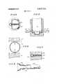
- FIG. 1is a perspective view of the bottle of the present invention exploded from its stand.
- FIG. 2is a cross-sectional view taken along line 22 of FIG. 1.
- FIG. 3is a cross-sectional view taken along line 3--3 of FIG. 2
- FIG. 4is a cross-sectional view taken along line 4-4 of FIG. 2.
- FIG. 5is a fragmentary cross-sectional view of the bottle in the mold showing means for providing the two indentations.
- FIG. 6-is a cross-sectional view looking towards the bottom with indentation forming means positioned at the beginning of a stroke.
- FIG. 7is' the same cross-sectional view as in FIG. 6 with indentation forming means at the close of a stroke.
- FIG. 8is a close up view partly in cross-section showing application of a tube to the nipple on the bottle of the present invention.
- FIG. 1depicts the bottle of the present invention.
- the bottleis constructed of a thermoplastic material such as polyethylene or polypropylene.
- the bottleis blow-molded and is produced in a completely sealed condition. That is, the bottle prior to completion of all the steps necessary to form the bottle is filled with a predetermined quantity of a liquid, such as water.
- the bottle 10has a fairly complex shape. Much of the shape and other structural features have already been disclosed in a prior patent application as mentioned in the above. The present being a considerable improvement over the latter. With regard thereto, attention is directed to the sealed nipple 11 positioned horizontally between the top conduit portion 12 of the bottle and the chamber 13 of the bottle.
- the nipple 1 1is formed integral with a substantially vertical breakaway member 14.
- the memberhas an elongated upper portion and a downwardly depending lower portion 16.
- the lower portionhas facing rearwardly a convenient finger grip 17 consisting of a concavity and rearwardly extending portions 18 and 19. In use the inside portion of a finger is placed in the concavity and the thumb is positioned on the outer forwardly facing surface 15.
- member 14By pivoting member 14 at the area of contact with the nipple, accomplished by moving the lower portion 16 forward, the member 14 may be easily broken off. The removal thereof provides communication to the inside of the bottle as exemplified in' FIG. 8.
- the nipple 11 freed of member 14may now have applied to it a tubular conduit 20 which is adapted to fit snugly onto the nipple having on the surface thereof a series of axially disposed serrations 21.
- Top conduit portion 12communicates with a conduit which is formed integral along one side of the bottle.
- the conduit 25terminates near the bottom portion of the bottle.
- the bottom portionhas the appearance of a foot 26.
- the conduit 25terminates into this foot.
- the foothas a bottom 27 which is, of course, also the bottom of the bottle.
- the footis separated from the main part of the bottle, that is, chamber 13 due to indentations 28 and perforated wall 29. It will be appreciated that when the bottle is used as a humidifier and oxygen is passed into the foot 26 it will be broken up into discrete bubbles when it passes through the perforations of wall 29.
- the perforations 30have, generally, a diamond-shaped configuration.
- Theconfigurationsare due to the unique mode of fabrication as will be now discussed.
- the elongated vertical conduitis molded integral with the formation of the bottle.
- the bottleis also molded in a similar fashion.
- theretois the utilization of special inserts in the mold dies having oppositely disposed protrusions having confronting non-mating notches as depicted in FIG. 6 by reference numeral 31.
- the molding surfacesare brought together as in essentially the same manner as when the integral conduit is formed. Now, however, the notches on the confronting leading edges of each side of the thermoplastic material is not brought together in a single sealing line.
- thermoplastic materialwill follow the irregular edges of the molding device, the diamondshaped openings will be formed as shown in FIG. 7.
- the two opposite sides of the thermoplastic materialwill touch and become affixed in that position after cooling the mold and thermoplastic material. Cooling is usually assisted by the introduction of the liquid with which the container is to be filled.
- F IG. 5shows another molding technique for producing the stated indentations and perforations. Being a cross-sectional view taken along a vertical line, the bottle is molded in accordance with the mentioned U.S. patent application. Openings 41 are provided at each side of the mold into which separate indentations producing means 42 are thrust having the notched leading edges, as in the other embodiment.
- a pedestal 51is associated 'with the bottle of the present invention. While the bottle has the capacity to remain in an upright position without a special pedestal, the fact that it is fairly narrow, plus the devices that are attached to the ports, some unbalance may occur.
- The'attachable and removable pedestalis designed to provide additional support.
- the pedestalhas a socket 52 which is an indentation in the upper surface of the pedestal.
- the upper surfacehas upstanding walls 53 at both sides of the socket 52.
- the indentation 53is adapted to accept the foot portion of the bottle in a fairly secure friction fitted manner.
- the upstanding walls 53are designed to part slightly as the foot is inserted and to then grasp more of the foot portion than would be possible with the indentation 52.
- the pedestalmay be constructed by injection molding techniques. As a result, the pedestal will be quite thin having no solid base and will be hollow underneath.
- thermoplastic bottlecomprising a chamber for containing a fluid, a lower portion, said lower portion being integrally formed with said chamber and being separated from each other by a relatively narrow band of thermoplastic material having a plurality of perforations whereby there is communication between the said chamber and the said lower portion, conduit means, said conduit means being integrally molded along a side of said chamber, one end of said conduit means terminating and communicating with the said lower portion, the other end of said conduit means terminating above said chamber with a breachable sealing means, said chamber having a' neck portion thereabove and below said upper terminating portion of said conduit means, a port meanspositioned between said chamber and said other end of said conduit means, said port means having an integral sealing means.
- thermoplastic bottle of claim 1wherein the said narrow band of thermoplastic material having the said perforations is perpendicular to the axis of said integral conduit.
- thermoplastic bottle of claim 1 wherein the integral sealing means on said port meansis an elongated breakaway member perpendicular to the axis of the port means.
- thermoplastic bottle of claim 5wherein the bottle has a base means, said base means has a relatively flat bottom, said base means has at the upper surface an elongated socket adapted to receive a portion of the said lower portion and to be retained together by a friction fit.
- thermoplastic bottle of claim 6wherein the said narrow band of thermoplastic material having the said perforations is perpendicular to the axis of said integral conduit.
- thermoplastic bottle of claim 7 wherein the integral sealing means in said port meansis an elongated breakaway member perpendicular to the axis of the port means.
Landscapes
- Health & Medical Sciences (AREA)
- Engineering & Computer Science (AREA)
- Anesthesiology (AREA)
- Biomedical Technology (AREA)
- Heart & Thoracic Surgery (AREA)
- Hematology (AREA)
- Life Sciences & Earth Sciences (AREA)
- Animal Behavior & Ethology (AREA)
- General Health & Medical Sciences (AREA)
- Public Health (AREA)
- Veterinary Medicine (AREA)
- Ceramic Engineering (AREA)
- Mechanical Engineering (AREA)
- Emergency Medicine (AREA)
- Pulmonology (AREA)
- Details Of Rigid Or Semi-Rigid Containers (AREA)
Abstract
Description
Claims (8)
Priority Applications (1)
| Application Number | Priority Date | Filing Date | Title |
|---|---|---|---|
| US00307460AUS3807713A (en) | 1972-11-17 | 1972-11-17 | Bottle containing fluid for inhalation therapy apparatus |
Applications Claiming Priority (1)
| Application Number | Priority Date | Filing Date | Title |
|---|---|---|---|
| US00307460AUS3807713A (en) | 1972-11-17 | 1972-11-17 | Bottle containing fluid for inhalation therapy apparatus |
Publications (1)
| Publication Number | Publication Date |
|---|---|
| US3807713Atrue US3807713A (en) | 1974-04-30 |
Family
ID=23189874
Family Applications (1)
| Application Number | Title | Priority Date | Filing Date |
|---|---|---|---|
| US00307460AExpired - LifetimeUS3807713A (en) | 1972-11-17 | 1972-11-17 | Bottle containing fluid for inhalation therapy apparatus |
Country Status (1)
| Country | Link |
|---|---|
| US (1) | US3807713A (en) |
Cited By (27)
| Publication number | Priority date | Publication date | Assignee | Title |
|---|---|---|---|---|
| US4012472A (en)* | 1975-07-17 | 1977-03-15 | Arbrook, Inc. | Medical fluids container |
| US4012473A (en)* | 1975-07-16 | 1977-03-15 | Arbrook, Inc. | Nebulizer-humidifier |
| US4012471A (en)* | 1975-06-06 | 1977-03-15 | Kunkle Jr George E | Disposable container |
| US4025590A (en)* | 1976-06-10 | 1977-05-24 | Victor Igich | Self-sealing humidifier for inhalation therapy |
| US4036919A (en)* | 1974-06-26 | 1977-07-19 | Inhalation Therapy Equipment, Inc. | Nebulizer-humidifier system |
| US4061698A (en)* | 1975-04-18 | 1977-12-06 | Aerwey Laboratories, Inc. | Humidifier-nebulizer apparatus |
| US4149556A (en)* | 1978-09-26 | 1979-04-17 | Respiratory Care, Inc. | Tubular connector having audible relief valve |
| US4172105A (en)* | 1979-02-15 | 1979-10-23 | Respiratory Care, Inc. | Pediatric cartridge humidifier |
| US4187951A (en)* | 1978-05-11 | 1980-02-12 | Respiratory Care, Inc. | Blow molded bottle with diffuser and method for making same |
| US4198969A (en)* | 1978-10-06 | 1980-04-22 | Baxter Travenol Laboratories, Inc. | Suction-operated nebulizer |
| USD258910S (en) | 1978-11-06 | 1981-04-14 | Baxter Travenol Laboratories, Inc. | Nebulizer cup |
| US4270934A (en)* | 1978-06-05 | 1981-06-02 | General Motors Corporation | Universal internal tube accumulator |
| JPS56111519U (en)* | 1980-01-25 | 1981-08-28 | ||
| JPS56109728A (en)* | 1980-01-24 | 1981-08-31 | Kendall & Co | Vessel* which is molded by blow* with diffuser and its manufacture |
| USD267975S (en) | 1980-08-20 | 1983-02-15 | Baxter Travenol Laboratories, Inc. | Nebulizer cup |
| US4838464A (en)* | 1987-06-11 | 1989-06-13 | Graham Engineering Corporation | Vented plastic bottle |
| US4865777A (en)* | 1986-09-19 | 1989-09-12 | Automatic Liquid Packaging, Inc. | Manufacture of humidifier container |
| US4891171A (en)* | 1986-09-19 | 1990-01-02 | Automatic Liquid Packaging, Inc. | Humidifier container |
| US5000674A (en)* | 1986-09-19 | 1991-03-19 | Automatic Liquid Packaging, Inc. | Manufacture of humidifier container and mold assembly therefor |
| EP0645157A3 (en)* | 1993-09-24 | 1995-06-07 | Kendall Med Erzeugnisse Gmbh | Container for the humidification of respiratory gas. |
| FR2807397A1 (en)* | 2000-04-07 | 2001-10-12 | Wolf Concept | CONTAINER FOR LIQUIDS |
| US20040140286A1 (en)* | 2002-12-19 | 2004-07-22 | Zoller Wolfgang P. | Container made of a transparent material having an insert in a side wall |
| USD505332S1 (en) | 2002-12-19 | 2005-05-24 | Wolf Concept S.A.R.L. | Container having an insert in a side wall |
| US20060202362A1 (en)* | 2002-07-25 | 2006-09-14 | Mitsuru Chiba | Liquid bag, liquid bag mouth member, and method of producing the same |
| CN103432676A (en)* | 2013-08-20 | 2013-12-11 | 宁波圣宇瑞医疗器械有限公司 | Humidification bottle with repeated using preventing function |
| US20180071464A1 (en)* | 2007-05-15 | 2018-03-15 | Caddo Medical Technologies Llc | Pre-Filled, Small-Volume Nebulizer and Method of Manufacture |
| US11065401B2 (en)* | 2018-11-21 | 2021-07-20 | Shl Medical Ag | Stand for medicament delivery device, and system comprising stand and medicament delivery device |
Citations (5)
| Publication number | Priority date | Publication date | Assignee | Title |
|---|---|---|---|---|
| US2753990A (en)* | 1953-07-02 | 1956-07-10 | Chalfin Philip | Container |
| US3509879A (en)* | 1967-11-24 | 1970-05-05 | American Hospital Supply Corp | Parenteral liquid container having frangible part structure |
| US3652015A (en)* | 1970-05-11 | 1972-03-28 | Respiratory Care | Nebulizer |
| US3682168A (en)* | 1970-06-10 | 1972-08-08 | Ahldea Corp | Sterile liquid entraining system |
| US3744771A (en)* | 1970-07-20 | 1973-07-10 | Ahldea Corp | Disposable liquid entraining system |
- 1972
- 1972-11-17USUS00307460Apatent/US3807713A/ennot_activeExpired - Lifetime
Patent Citations (5)
| Publication number | Priority date | Publication date | Assignee | Title |
|---|---|---|---|---|
| US2753990A (en)* | 1953-07-02 | 1956-07-10 | Chalfin Philip | Container |
| US3509879A (en)* | 1967-11-24 | 1970-05-05 | American Hospital Supply Corp | Parenteral liquid container having frangible part structure |
| US3652015A (en)* | 1970-05-11 | 1972-03-28 | Respiratory Care | Nebulizer |
| US3682168A (en)* | 1970-06-10 | 1972-08-08 | Ahldea Corp | Sterile liquid entraining system |
| US3744771A (en)* | 1970-07-20 | 1973-07-10 | Ahldea Corp | Disposable liquid entraining system |
Cited By (35)
| Publication number | Priority date | Publication date | Assignee | Title |
|---|---|---|---|---|
| US4036919A (en)* | 1974-06-26 | 1977-07-19 | Inhalation Therapy Equipment, Inc. | Nebulizer-humidifier system |
| US4061698A (en)* | 1975-04-18 | 1977-12-06 | Aerwey Laboratories, Inc. | Humidifier-nebulizer apparatus |
| US4100235A (en)* | 1975-04-18 | 1978-07-11 | Aerwey Laboratories, Inc. | Humidifier-nebulizer apparatus |
| US4012471A (en)* | 1975-06-06 | 1977-03-15 | Kunkle Jr George E | Disposable container |
| US4012473A (en)* | 1975-07-16 | 1977-03-15 | Arbrook, Inc. | Nebulizer-humidifier |
| US4012472A (en)* | 1975-07-17 | 1977-03-15 | Arbrook, Inc. | Medical fluids container |
| US4025590A (en)* | 1976-06-10 | 1977-05-24 | Victor Igich | Self-sealing humidifier for inhalation therapy |
| US4187951A (en)* | 1978-05-11 | 1980-02-12 | Respiratory Care, Inc. | Blow molded bottle with diffuser and method for making same |
| US4270934A (en)* | 1978-06-05 | 1981-06-02 | General Motors Corporation | Universal internal tube accumulator |
| US4149556A (en)* | 1978-09-26 | 1979-04-17 | Respiratory Care, Inc. | Tubular connector having audible relief valve |
| US4198969A (en)* | 1978-10-06 | 1980-04-22 | Baxter Travenol Laboratories, Inc. | Suction-operated nebulizer |
| USD258910S (en) | 1978-11-06 | 1981-04-14 | Baxter Travenol Laboratories, Inc. | Nebulizer cup |
| FR2449389A1 (en)* | 1979-02-15 | 1980-09-12 | Kendall & Co | CARTRIDGE HUMIDIFIER FOR USE IN PEDIATRICS |
| US4172105A (en)* | 1979-02-15 | 1979-10-23 | Respiratory Care, Inc. | Pediatric cartridge humidifier |
| JPS56109728A (en)* | 1980-01-24 | 1981-08-31 | Kendall & Co | Vessel* which is molded by blow* with diffuser and its manufacture |
| JPS56111519U (en)* | 1980-01-25 | 1981-08-28 | ||
| USD267975S (en) | 1980-08-20 | 1983-02-15 | Baxter Travenol Laboratories, Inc. | Nebulizer cup |
| US4865777A (en)* | 1986-09-19 | 1989-09-12 | Automatic Liquid Packaging, Inc. | Manufacture of humidifier container |
| US4891171A (en)* | 1986-09-19 | 1990-01-02 | Automatic Liquid Packaging, Inc. | Humidifier container |
| US5000674A (en)* | 1986-09-19 | 1991-03-19 | Automatic Liquid Packaging, Inc. | Manufacture of humidifier container and mold assembly therefor |
| US4838464A (en)* | 1987-06-11 | 1989-06-13 | Graham Engineering Corporation | Vented plastic bottle |
| EP0382967A3 (en)* | 1989-01-19 | 1992-03-04 | Automatic Liquid Packaging, Inc. | Manufacture of humidifier container and mold assembly therefor |
| EP0702974A2 (en) | 1989-01-19 | 1996-03-27 | Automatic Liquid Packaging, Inc. | Humidifier container |
| EP0645157A3 (en)* | 1993-09-24 | 1995-06-07 | Kendall Med Erzeugnisse Gmbh | Container for the humidification of respiratory gas. |
| WO2001076953A1 (en)* | 2000-04-07 | 2001-10-18 | Wolf Concept | Container for liquids |
| FR2807397A1 (en)* | 2000-04-07 | 2001-10-12 | Wolf Concept | CONTAINER FOR LIQUIDS |
| US20060202362A1 (en)* | 2002-07-25 | 2006-09-14 | Mitsuru Chiba | Liquid bag, liquid bag mouth member, and method of producing the same |
| US7198255B2 (en)* | 2002-07-25 | 2007-04-03 | Senko Medical Instrument Mig. Co., Ltd. | Liquid bag, liquid bag mouth member, and method of producing the same |
| US20040140286A1 (en)* | 2002-12-19 | 2004-07-22 | Zoller Wolfgang P. | Container made of a transparent material having an insert in a side wall |
| USD505332S1 (en) | 2002-12-19 | 2005-05-24 | Wolf Concept S.A.R.L. | Container having an insert in a side wall |
| US7357265B2 (en) | 2002-12-19 | 2008-04-15 | Wolf Concept S.A.R.L. | Container made of a transparent material having an insert in a side wall |
| US20180071464A1 (en)* | 2007-05-15 | 2018-03-15 | Caddo Medical Technologies Llc | Pre-Filled, Small-Volume Nebulizer and Method of Manufacture |
| US10149950B2 (en)* | 2007-05-15 | 2018-12-11 | Caddo Medical Technologies Llc | Pre-filled, small-volume nebulizer and method of manufacture |
| CN103432676A (en)* | 2013-08-20 | 2013-12-11 | 宁波圣宇瑞医疗器械有限公司 | Humidification bottle with repeated using preventing function |
| US11065401B2 (en)* | 2018-11-21 | 2021-07-20 | Shl Medical Ag | Stand for medicament delivery device, and system comprising stand and medicament delivery device |
Similar Documents
| Publication | Publication Date | Title |
|---|---|---|
| US3807713A (en) | Bottle containing fluid for inhalation therapy apparatus | |
| US3892235A (en) | Multi-use inhalation therapy apparatus | |
| US4101041A (en) | Prefillable, hermetically sealed container adapted for use with a humidifier or nebulizer head | |
| US3864326A (en) | Spraying devices, in particular nebulizing devices | |
| US2951644A (en) | Dispensing device | |
| US4036919A (en) | Nebulizer-humidifier system | |
| US3097645A (en) | Nebulizer | |
| USRE37734E1 (en) | Dispensing bulb | |
| CN100536953C (en) | Liquid storage bag, pocket member for liquid storage bag and manufacturing method thereof | |
| US4267974A (en) | Nebulizer device | |
| US3804280A (en) | Multi-use inhalation therapy apparatus | |
| JPH08159015A (en) | Foamed raw-material distributing weighing apparatus | |
| US3162370A (en) | Container, atomizer and adapter spraying device | |
| US4865777A (en) | Manufacture of humidifier container | |
| ATE94042T1 (en) | DEVICE FOR DELIVERING FLOWABLE MEDIA. | |
| JPH0510146B2 (en) | ||
| JPWO2002087675A1 (en) | Liquid bags and liquid bag assemblies | |
| JPS6349371U (en) | ||
| CN220083265U (en) | Indoor air improvement components and packaging | |
| CN211244996U (en) | Aerosol administration device | |
| JPH0441284U (en) | ||
| CN2477198Y (en) | Surface medicinal spraying vessel for nasal cavity and pharyngeal cavity | |
| CN214970481U (en) | Atomizer | |
| JP7344615B1 (en) | chemical sprayer | |
| CN217138877U (en) | Disposable atomizer for respiratory tract |
Legal Events
| Date | Code | Title | Description |
|---|---|---|---|
| PS | Patent suit(s) filed | ||
| AS | Assignment | Owner name:MANUFACTURERS HANOVER TRUST COMPANY Free format text:SECURITY INTEREST;ASSIGNOR:RESPIRATORY CARE INC.;REEL/FRAME:005060/0188 Effective date:19881031 | |
| AS | Assignment | Owner name:RESPIRATORY CARE, INC., ILLINOIS Free format text:RELEASED BY SECURED PARTY;ASSIGNOR:MANUFACTURERS HANOVER TRUST COMPANY, AS AGENT;REEL/FRAME:005249/0733 Effective date:19890712 | |
| AS | Assignment | Owner name:HUDSON OXYGEN THERAPY SALES COMPANY, A CA CORP., C Free format text:ASSIGNMENT OF ASSIGNORS INTEREST.;ASSIGNOR:RESPIRATORY CARE, INC.;REEL/FRAME:005228/0683 Effective date:19890712 | |
| AS | Assignment | Owner name:FIRST INTERSTATE BANK OF CALIFORNIA Free format text:SECURITY INTEREST;ASSIGNOR:HUDSON RESPIRATORY CARE, INC.;REEL/FRAME:005302/0948 Effective date:19900209 | |
| AS | Assignment | Owner name:HOMEFED BANK, F.S.B. Free format text:SECURITY INTEREST;ASSIGNOR:HUDSON RESPIRATORY CARE INC.;REEL/FRAME:005300/0204 Effective date:19900509 | |
| AS | Assignment | Owner name:CREDITANSTALT-BANKVEREIN, CALIFORNIA Free format text:ASSIGNMENT OF ASSIGNORS INTEREST;ASSIGNOR:HUDSON RESPIRATORY CARE INC.;REEL/FRAME:006570/0759 Effective date:19920914 |