US3807403A - Cryosurgical apparatus - Google Patents
Cryosurgical apparatusDownload PDFInfo
- Publication number
- US3807403A US3807403AUS00262543AUS26254372AUS3807403AUS 3807403 AUS3807403 AUS 3807403AUS 00262543 AUS00262543 AUS 00262543AUS 26254372 AUS26254372 AUS 26254372AUS 3807403 AUS3807403 AUS 3807403A
- Authority
- US
- United States
- Prior art keywords
- exhaust conduit
- instrument
- conduit
- probe tip
- gas
- Prior art date
- Legal status (The legal status is an assumption and is not a legal conclusion. Google has not performed a legal analysis and makes no representation as to the accuracy of the status listed.)
- Expired - Lifetime
Links
- 239000000523sampleSubstances0.000claimsabstractdescription26
- 239000012212insulatorSubstances0.000claimsabstractdescription18
- 239000012530fluidSubstances0.000claimsdescription7
- 238000004891communicationMethods0.000claimsdescription2
- 238000010276constructionMethods0.000abstractdescription8
- 230000008602contractionEffects0.000abstractdescription4
- 239000007789gasSubstances0.000description30
- 230000035882stressEffects0.000description3
- 238000010257thawingMethods0.000description3
- CURLTUGMZLYLDI-UHFFFAOYSA-NCarbon dioxideChemical compoundO=C=OCURLTUGMZLYLDI-UHFFFAOYSA-N0.000description2
- GQPLMRYTRLFLPF-UHFFFAOYSA-NNitrous OxideChemical compound[O-][N+]#NGQPLMRYTRLFLPF-UHFFFAOYSA-N0.000description2
- 239000004809TeflonSubstances0.000description2
- 229920006362Teflon®Polymers0.000description2
- 230000005680Thomson effectEffects0.000description2
- 238000004519manufacturing processMethods0.000description2
- 229910001220stainless steelInorganic materials0.000description2
- 239000010935stainless steelSubstances0.000description2
- 238000001356surgical procedureMethods0.000description2
- RYGMFSIKBFXOCR-UHFFFAOYSA-NCopperChemical compound[Cu]RYGMFSIKBFXOCR-UHFFFAOYSA-N0.000description1
- XUIMIQQOPSSXEZ-UHFFFAOYSA-NSiliconChemical compound[Si]XUIMIQQOPSSXEZ-UHFFFAOYSA-N0.000description1
- 229910000831SteelInorganic materials0.000description1
- 208000006374Uterine CervicitisDiseases0.000description1
- 229910002092carbon dioxideInorganic materials0.000description1
- 239000001569carbon dioxideSubstances0.000description1
- 206010008323cervicitisDiseases0.000description1
- 239000003795chemical substances by applicationSubstances0.000description1
- 230000006835compressionEffects0.000description1
- 238000007906compressionMethods0.000description1
- 238000001816coolingMethods0.000description1
- 229910052802copperInorganic materials0.000description1
- 239000010949copperSubstances0.000description1
- 230000000994depressogenic effectEffects0.000description1
- 230000001627detrimental effectEffects0.000description1
- 238000004880explosionMethods0.000description1
- 239000011152fibreglassSubstances0.000description1
- 238000012986modificationMethods0.000description1
- 230000004048modificationEffects0.000description1
- 230000017074necrotic cell deathEffects0.000description1
- 239000001272nitrous oxideSubstances0.000description1
- 230000000717retained effectEffects0.000description1
- 229910052710siliconInorganic materials0.000description1
- 239000010703siliconSubstances0.000description1
- 239000010959steelSubstances0.000description1
- 230000008646thermal stressEffects0.000description1
Images

Classifications
- A—HUMAN NECESSITIES
- A61—MEDICAL OR VETERINARY SCIENCE; HYGIENE
- A61F—FILTERS IMPLANTABLE INTO BLOOD VESSELS; PROSTHESES; DEVICES PROVIDING PATENCY TO, OR PREVENTING COLLAPSING OF, TUBULAR STRUCTURES OF THE BODY, e.g. STENTS; ORTHOPAEDIC, NURSING OR CONTRACEPTIVE DEVICES; FOMENTATION; TREATMENT OR PROTECTION OF EYES OR EARS; BANDAGES, DRESSINGS OR ABSORBENT PADS; FIRST-AID KITS
- A61F7/00—Heating or cooling appliances for medical or therapeutic treatment of the human body
- A61F7/12—Devices for heating or cooling internal body cavities
- A—HUMAN NECESSITIES
- A61—MEDICAL OR VETERINARY SCIENCE; HYGIENE
- A61B—DIAGNOSIS; SURGERY; IDENTIFICATION
- A61B18/00—Surgical instruments, devices or methods for transferring non-mechanical forms of energy to or from the body
- A61B18/02—Surgical instruments, devices or methods for transferring non-mechanical forms of energy to or from the body by cooling, e.g. cryogenic techniques
- F—MECHANICAL ENGINEERING; LIGHTING; HEATING; WEAPONS; BLASTING
- F25—REFRIGERATION OR COOLING; COMBINED HEATING AND REFRIGERATION SYSTEMS; HEAT PUMP SYSTEMS; MANUFACTURE OR STORAGE OF ICE; LIQUEFACTION SOLIDIFICATION OF GASES
- F25B—REFRIGERATION MACHINES, PLANTS OR SYSTEMS; COMBINED HEATING AND REFRIGERATION SYSTEMS; HEAT PUMP SYSTEMS
- F25B2309/00—Gas cycle refrigeration machines
- F25B2309/02—Gas cycle refrigeration machines using the Joule-Thompson effect
- F25B2309/021—Gas cycle refrigeration machines using the Joule-Thompson effect with a cryosurgical probe tip having a specific construction
- F—MECHANICAL ENGINEERING; LIGHTING; HEATING; WEAPONS; BLASTING
- F25—REFRIGERATION OR COOLING; COMBINED HEATING AND REFRIGERATION SYSTEMS; HEAT PUMP SYSTEMS; MANUFACTURE OR STORAGE OF ICE; LIQUEFACTION SOLIDIFICATION OF GASES
- F25B—REFRIGERATION MACHINES, PLANTS OR SYSTEMS; COMBINED HEATING AND REFRIGERATION SYSTEMS; HEAT PUMP SYSTEMS
- F25B2309/00—Gas cycle refrigeration machines
- F25B2309/02—Gas cycle refrigeration machines using the Joule-Thompson effect
- F25B2309/022—Gas cycle refrigeration machines using the Joule-Thompson effect characterised by the expansion element
Definitions
- cryosurgical apparatusof the type which operates from a source of compressed gas. It includes an improved nozzle which is substantially less critical tnan prior art nozzles and permits simplified andless expensive construction. A defrost valve in the exhaust conduit permits easy and quiet operation by the surgeon. An insulator tube is resiliently secured to the probe to allow thermal expansion and contraction without stress.
- the gas expansion orificeis of an extremely small size and in all prior art instruments the spacing between the orifice and the inner wall of the cooling tip is extremely critical. For example, with prior art instruments, the orifice is positioned approximately 0.050 inch from the inner wall of the tip and the permitted tolerance is only 0.010 inch. This resultsin such instruments being difficult and costly to manufacture. For example, the parts of such instruments are commonly threaded so that they may be factory adjusted prior to shipment.
- the inventioncomprises a gas operated cryosurgical instrument including a tubular exhaust conduit terminating at one end in a hollow probe tip of high thermal conductivity.
- a high pressure gas delivery conduitextends through the exhaust conduit and terminates at a nozzle within the probe tip.
- Thenozzlehas a cylindrical gas discharge passage of smaller diameter than the delivery conduit and a smoothly curved reduction passage therebetween.
- a normally open valveis connected in fluid flow relationship with the exhaust conduit.
- An insulator tubesurrounds but is spaced from the exhaust conduit and is connected thereto by-a resilient connection.
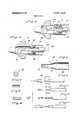
- FIG. 1is a perspective view of a cryosurgical instrument in accordance with the present invention shown connected to a source of bottled gas;
- FIG. 2is an enlarged cross section taken through the instrument of FIG. 1;
- FIG. 3is an enlarged cross section of the exhaust valve of FIG. 2;
- FIG. 4is a greatly enlarged cross section of the nozzle portion of the apparatus
- FIG. 5is an illustration of the gas jet obtained with the nozzle of FIG/4;
- FIG. 6is a cross section taken substantially along the line 6-6 of FIG. 5; g
- FIG. 7is an illustration of one type nozzle used in the .prior art.
- FIG. 8is a cross section taken substantially along the line 88 of FIG. 7;
- FIG. 9is an illustration of another type of nozzle used in the prior art.
- FIG. 10is an enlarged cross section showing the orifice of the FIG. 9 nozzle
- FIG. 11shows still another type of nozzle used in the prior art
- FIG. 12illustrates the resilient connection between the warm insulator tube and the cold portions of the probe; and g FIG. 13 is an illustration similar to FIG. 12 showing the manner in which the resilient connection operates.
- an instrument of the type utilized in treating cervicitiscomprises an elongated probe 10 mounted in a handle 12 and terminating in a substantially conical applicator tip 14. The other end of the probe extends from the handle and is connected to a line 16 which, in turn, is connected to a suitable source 18 of pressurized gas. Atrigger 20 extends from the handle for selective defrosting as will be explained.
- FIG. 2the handle 12 will be seen to support the rear portion 22a of a stainless steel insulator tube 22.
- the rear portion 220 and a forward portion 22bare each welded to the circumferential flange 24 of an internally threaded sleeve 26. Threaded into sleeve 26 is a bushing 28 which is welded to the end of an exhaust tube 30.
- the end of exhaust tube 30has a bevelled valve seat 32 as shown in FIG. 3.
- the other end of exhaust tube 30is welded to a bushing 34 which, in turn, is welded to the cylindrical stem 36 of the hollow copper tip 14.
- the forward end of the insulator tube 22extends over the surface of stem 36 but is not secured thereto. Instead, a resilient bushing 38 frictionally engages both the exhaust tube 30 and the insulator tube 32.
- the line 16is a coaxial conduit comprising a silicon coated fiberglass exhaust line 40 secured by a spring 42 to the end of insulator tube 22. Carried within the exhaust line is a high pressure delivery line 44 secured by means of a high pressure connector 46 to the threaded end 48 of a steel valve member 50 which is illustrated in more detail in FIG. 3.
- the valve member 50in addition to the threaded end 48, has an unthreaded forward portion 52 and a central circumferential flange 54.
- the forward surface of flange 54carries a circular knife edge 56.
- a Teflon valve member 58is press fitted over the forward portion 52 and has a flat rear surface which engages the knife edge 56.
- the forward surface of valve seat 58is tapered to engage the valve seat 32 on exhaust tube 30.
- the upper end of trigger 20defines a drilled opening 60 through which the threaded end 48 of valve member 50 extends. It is held in place by a nut 62.
- the trigger 20is mounted on a pivot 64 positioned approximately one inch below its upper end. The length of trigger 20 below the pivot 64 is approximately 4 inches in the described embodiment.
- a delivery tube 66which in one embodiment is a 15 gauge stainless steel hypodermic tube having an internal diameter of 0.059 inch.
- the forward end of delivery tube 66has a reduced diameter portion forming a nozzle 68 positioned within the hollow probe tip 14.
- nozzle 68The construction of nozzle 68 will be best understood by reference to FIG. 4.
- the internal diameter of the delivery tube.66is reduced via a smooth wall reduction passage 70 to a cylindrical gas discharge passage 72.
- This configurationis achieved by inserting into the end of the hypodermic tube a hardened wire having an external diameter equal to the desired diameter of the gas discharge passage. The end of the tube is then swaged onto the wire and the wire is removed.
- the tube 66has an internal diameter of 0.059 inch and the internal diameter of the gas discharge passage 72 is 0.01065 inch.
- the distance from the nozzle to the beginning of reduction (A FIG. 4)is 0.20 inch and the distance between the nozzle tip and the end of reduction (B) is 0.12 inch.
- the performance of the nozzle 68is strikingly superior to those of the prior art. The reason for this is not fully understood but is believed to be due to the smooth continuous inner surface formed by the reduction passage 70 and the gas discharge passage 72. This is believed to prevent gas turbulence and permit laminar fiow out of nozzle 68.
- FIG.illustrates the gas flow from the nozzle 68 as actually observed in practice. As will be seen, it presents an elongated flame like" appearance and shape.
- FIGS. 7-11illustrate three prior art nozzle constructions and the jets obtained thereby.
- FIGS. 7 and 8illustrate a pinched tube configuration.
- FIGS. 9 andillustrate a rolled end construction and
- FIG. 11illustrates a type of orifice known as a double reduction orifice which comprises a series of tubes of reduced diameter.
- the jets from these prior art nozzlesappear as indicated.
- the distance from the orifice to the wall of the applicator tipis very critical and the spacing must be quite close. As an example, this distance may be 0.050 inch with a tolerance of or 0.0l0 inch.
- the distance from the nozzle tip to the wallmay be 0.250 inch with a tolerance of or -0.060 inch. Accordingly, by means of this invention, manufacture and assembly are greatly simplified, resulting in a highly effective instrument at a much lower cost.
- the resilient tip constructionis illustrated in detail in FIGS. 12 and 13.
- the insulator tube 22is spaced from exhaust tube 30, providing an insulating air space therebetween.
- the end of the insulator tube 22slidingly encircles the stem 36 of tip 14.
- a resilient bushing 38engages both the insulator tube and the exhaust tube. As the probe tip is cooled, the tip 14 and the exhaust line 30 will both cool and contract. This is shown in an exaggerated manner in FIG. 13 wherein it will be seen that the normal resilience of bushing 38 compensates for expansion and contraction and prevents stresses from building up in the instrument.
- the nozzle and the resilient tip constructionmay be utilized in connection with either a non-defrostable or a defrostable cryosurgical probe.
- the probe illustrated hereinis of the defrostable type. Defrosting is obtained by means of the valve illustrated in detail in FIG. 3.
- high pressure gas entering through delivery line 44passes through the hollow passage in the valve member 50 an through delivery tube 66 to nozzle 68. From the nozzle it expands into tip 14, causing the tip to be cooled by the Joule Thomson effect. The expanded gas then passes rearwardly through exhaust tube 30 and out the exhaust line 40. It may then be exhausted to atmosphere through any suitable opening such as the vent 74 shown in FIG. 1.
- the high pressure exhaust gastends to maintain the exhaust valve in its normally open position without the need for springs or similar devices.
- the trigger 20is depressed by the surgeon, whereupon it assumes the dashed line position illustrated in FIG. 2 and forces the Teflon valve member 58 against the bevelled valve seat 32'of the exhaust tube 30.
- the circular knife edge 56forms a gas tight seal with the rear of the valve member. With the exhaust valve closed, the gas pressure within tip 14 rises to bottle pressure and the heat of compression causes rapid defrosting of the probe tip.
- the diameter of the valve member 58 which is exposed to gas pressureis approximately 0.187 inch.
- a gas operated cryosurgical instrumentwhich comprises: a tubular exhaust conduit terminating at one end in a hollow probe tip of high thermal conductivity; a remote source of high pressure gas; a gas delivery conduit extending through said exhaust conduit in fluid flow communication with said source and terminating at a nozzle within said probe tip; normally open valve means connected in fluid flow relationship between said exhaust conduit and atmosphere; and means for controllably closing and opening said valve means.
- valve meanscomprises: a stationary valve seat defined by saidexhaust conduit; and a moveable valve member carried by said delivery conduit.
- closing meanscomprises a manually operable trigger connected to advance both of said delivery conduit and valve member.
- a gas operated cryosurgical instrumentwhich comprises: a tubular exhaust conduit terminating at one end in a hollow probe tip of high thermal conductivity; a gas delivery conduit extending through said exhaust conduit and terminating at a nozzle within said probe tip,-said nozzle including a cylindrical gas discharge passage of smaller diameter than said delivery conduit and a smoothly curved reduction passage therebetween; normally open valve means connected in fluid flow relationship between said exhaust conduit and atmosphere; an insulator tube surrounding, but spaced from, said exhaust conduit; resilient means interconnecting said insulatortube and exhaust conduit; and means for controllably closing and opening said valve means.
- said resilient meanscomprises an annular bushing encircling said exhaust conduit adjacent said probe tip and frictionally engaging both of said exhaust conduit and insulator tube to permit relative motion therebetween.
Landscapes
- Health & Medical Sciences (AREA)
- Life Sciences & Earth Sciences (AREA)
- Surgery (AREA)
- Animal Behavior & Ethology (AREA)
- Public Health (AREA)
- Heart & Thoracic Surgery (AREA)
- Nuclear Medicine, Radiotherapy & Molecular Imaging (AREA)
- Engineering & Computer Science (AREA)
- Veterinary Medicine (AREA)
- General Health & Medical Sciences (AREA)
- Biomedical Technology (AREA)
- Physics & Mathematics (AREA)
- Vascular Medicine (AREA)
- Thermal Sciences (AREA)
- Otolaryngology (AREA)
- Medical Informatics (AREA)
- Molecular Biology (AREA)
- Surgical Instruments (AREA)
Abstract
Description
Claims (6)
Priority Applications (2)
| Application Number | Priority Date | Filing Date | Title |
|---|---|---|---|
| US00262543AUS3807403A (en) | 1972-06-14 | 1972-06-14 | Cryosurgical apparatus |
| US413684AUS3886945A (en) | 1972-06-14 | 1973-11-07 | Cryosurgical apparatus |
Applications Claiming Priority (1)
| Application Number | Priority Date | Filing Date | Title |
|---|---|---|---|
| US00262543AUS3807403A (en) | 1972-06-14 | 1972-06-14 | Cryosurgical apparatus |
Publications (1)
| Publication Number | Publication Date |
|---|---|
| US3807403Atrue US3807403A (en) | 1974-04-30 |
Family
ID=22997946
Family Applications (1)
| Application Number | Title | Priority Date | Filing Date |
|---|---|---|---|
| US00262543AExpired - LifetimeUS3807403A (en) | 1972-06-14 | 1972-06-14 | Cryosurgical apparatus |
Country Status (1)
| Country | Link |
|---|---|
| US (1) | US3807403A (en) |
Cited By (61)
| Publication number | Priority date | Publication date | Assignee | Title |
|---|---|---|---|---|
| US3886945A (en)* | 1972-06-14 | 1975-06-03 | Frigitronics Of Conn Inc | Cryosurgical apparatus |
| US3933156A (en)* | 1974-01-15 | 1976-01-20 | Giovanni Riggi | Cooling apparatus particularly for medical-surgical use |
| US4211231A (en)* | 1978-05-15 | 1980-07-08 | Cryomedics, Inc. | Cryosurgical instrument |
| US4236518A (en)* | 1978-04-14 | 1980-12-02 | Gyne-Tech Instrument Corporation | Cryogenic device selectively operable in a continuous freezing mode, a continuous thawing mode or a combination thereof |
| US4345598A (en)* | 1980-03-07 | 1982-08-24 | Vyzkumny Ustav Silnoproude Elektrotechniky | Cryogenic apparatus for surgery |
| US4831846A (en)* | 1988-04-12 | 1989-05-23 | The United States Of America As Represented By The United States Department Of Energy | Low temperature cryoprobe |
| US5433717A (en)* | 1993-03-23 | 1995-07-18 | The Regents Of The University Of California | Magnetic resonance imaging assisted cryosurgery |
| US6161543A (en)* | 1993-02-22 | 2000-12-19 | Epicor, Inc. | Methods of epicardial ablation for creating a lesion around the pulmonary veins |
| EP1102666A1 (en)* | 1998-08-06 | 2001-05-30 | Aga Aktiebolag | Point cooling |
| US20030191462A1 (en)* | 1996-05-03 | 2003-10-09 | Jacobs Clemens J. | Method for interrupting conduction paths within the heart |
| US20040015219A1 (en)* | 2002-05-16 | 2004-01-22 | Francischelli David E. | Device and method for ablation of cardiac tissue |
| US20040049179A1 (en)* | 2001-04-26 | 2004-03-11 | Francischelli David E. | Ablation system |
| US20040078069A1 (en)* | 2001-12-11 | 2004-04-22 | Francischelli David E. | Method and system for treatment of atrial tachyarrhythmias |
| US20040138621A1 (en)* | 2003-01-14 | 2004-07-15 | Jahns Scott E. | Devices and methods for interstitial injection of biologic agents into tissue |
| US20040138656A1 (en)* | 2000-04-27 | 2004-07-15 | Francischelli David E. | System and method for assessing transmurality of ablation lesions |
| US20040143260A1 (en)* | 2001-04-26 | 2004-07-22 | Francischelli David E. | Method and apparatus for tissue ablation |
| US20040215183A1 (en)* | 1995-02-22 | 2004-10-28 | Medtronic, Inc. | Apparatus and method for creating, maintaining, and controlling a virtual electrode used for the ablation of tissue |
| US20040220560A1 (en)* | 2003-04-29 | 2004-11-04 | Briscoe Roderick E. | Endocardial dispersive electrode for use with a monopolar RF ablation pen |
| US20040236322A1 (en)* | 1997-07-18 | 2004-11-25 | Mulier Peter M.J. | Device and method for ablating tissue |
| US20040267326A1 (en)* | 2002-01-25 | 2004-12-30 | Ocel Jon M | Cardiac mapping instrument with shapeable electrode |
| US20050165392A1 (en)* | 2002-01-25 | 2005-07-28 | Medtronic, Inc. | System and method of performing an electrosurgical procedure |
| US20050256522A1 (en)* | 2004-05-12 | 2005-11-17 | Medtronic, Inc. | Device and method for determining tissue thickness and creating cardiac ablation lesions |
| US20050267454A1 (en)* | 2000-01-19 | 2005-12-01 | Medtronic, Inc. | Methods of using high intensity focused ultrasound to form an ablated tissue area containing a plurality of lesions |
| US20050273006A1 (en)* | 2000-10-10 | 2005-12-08 | Medtronic, Inc. | Heart wall ablation/mapping catheter and method |
| US20060009759A1 (en)* | 2004-06-02 | 2006-01-12 | Chrisitian Steven C | Loop ablation apparatus and method |
| US20060009756A1 (en)* | 2004-05-14 | 2006-01-12 | Francischelli David E | Method and devices for treating atrial fibrillation by mass ablation |
| US20060009760A1 (en)* | 1998-07-07 | 2006-01-12 | Medtronic, Inc. | Method and apparatus for creating a bi-polar virtual electrode used for the ablation of tissue |
| US20060020263A1 (en)* | 2004-06-02 | 2006-01-26 | Rothstein Paul T | Clamping ablation tool and method |
| US20060020271A1 (en)* | 2004-06-18 | 2006-01-26 | Stewart Mark T | Methods and devices for occlusion of an atrial appendage |
| US20060025756A1 (en)* | 2000-01-19 | 2006-02-02 | Francischelli David E | Methods of using high intensity focused ultrasound to form an ablated tissue area |
| US20060036236A1 (en)* | 2004-06-02 | 2006-02-16 | Rothstein Paul T | Compound bipolar ablation device and method |
| US20060041254A1 (en)* | 2002-10-30 | 2006-02-23 | Medtronic, Inc. | Electrosurgical hemostat |
| US20060052770A1 (en)* | 1998-07-07 | 2006-03-09 | Medtronic, Inc. | Helical needle apparatus for creating a virtual electrode used for the ablation of tissue |
| US7118566B2 (en) | 2002-05-16 | 2006-10-10 | Medtronic, Inc. | Device and method for needle-less interstitial injection of fluid for ablation of cardiac tissue |
| US20060229594A1 (en)* | 2000-01-19 | 2006-10-12 | Medtronic, Inc. | Method for guiding a medical device |
| US7166105B2 (en) | 1995-02-22 | 2007-01-23 | Medtronic, Inc. | Pen-type electrosurgical instrument |
| US20070118107A1 (en)* | 2000-04-27 | 2007-05-24 | Francischelli David E | Vibration sensitive ablation device and method |
| US7250048B2 (en) | 2001-04-26 | 2007-07-31 | Medtronic, Inc. | Ablation system and method of use |
| US20080015562A1 (en)* | 2001-04-26 | 2008-01-17 | Medtronic, Inc. | Transmural ablation systems and methods |
| US20080039746A1 (en)* | 2006-05-25 | 2008-02-14 | Medtronic, Inc. | Methods of using high intensity focused ultrasound to form an ablated tissue area containing a plurality of lesions |
| US7435250B2 (en) | 2000-04-27 | 2008-10-14 | Medtronic, Inc. | Method and apparatus for tissue ablation |
| US20080275439A1 (en)* | 2002-01-25 | 2008-11-06 | David Francischelli | Cardiac ablation and electrical interface system and instrument |
| US7507235B2 (en) | 2001-01-13 | 2009-03-24 | Medtronic, Inc. | Method and system for organ positioning and stabilization |
| US7566334B2 (en) | 2004-06-02 | 2009-07-28 | Medtronic, Inc. | Ablation device with jaws |
| US7615015B2 (en) | 2000-01-19 | 2009-11-10 | Medtronic, Inc. | Focused ultrasound ablation devices having selectively actuatable emitting elements and methods of using the same |
| US20090299365A1 (en)* | 2008-05-13 | 2009-12-03 | Medtronic , Inc. | Tissue Lesion Evaluation |
| US7628780B2 (en) | 2001-01-13 | 2009-12-08 | Medtronic, Inc. | Devices and methods for interstitial injection of biologic agents into tissue |
| US20100042110A1 (en)* | 2004-06-18 | 2010-02-18 | Medtronic, Inc. | Method and system for placement of electrical lead inside heart |
| US20100145361A1 (en)* | 2004-06-18 | 2010-06-10 | Francischelli David E | Methods and Devices for Occlusion of an Atrial Appendage |
| US7740623B2 (en) | 2001-01-13 | 2010-06-22 | Medtronic, Inc. | Devices and methods for interstitial injection of biologic agents into tissue |
| US7818039B2 (en) | 2000-04-27 | 2010-10-19 | Medtronic, Inc. | Suction stabilized epicardial ablation devices |
| US7824399B2 (en) | 2001-04-26 | 2010-11-02 | Medtronic, Inc. | Ablation system and method of use |
| US8512337B2 (en) | 2001-04-26 | 2013-08-20 | Medtronic, Inc. | Method and system for treatment of atrial tachyarrhythmias |
| US8568409B2 (en) | 2000-03-06 | 2013-10-29 | Medtronic Advanced Energy Llc | Fluid-assisted medical devices, systems and methods |
| US8632533B2 (en) | 2009-02-23 | 2014-01-21 | Medtronic Advanced Energy Llc | Fluid-assisted electrosurgical device |
| US8663245B2 (en) | 2004-06-18 | 2014-03-04 | Medtronic, Inc. | Device for occlusion of a left atrial appendage |
| US9381061B2 (en) | 2000-03-06 | 2016-07-05 | Medtronic Advanced Energy Llc | Fluid-assisted medical devices, systems and methods |
| RU167325U1 (en)* | 2016-04-13 | 2017-01-10 | Общество с ограниченной ответственностью инновационное предприятие 'Биостандарт" (ООО ИП "Биостандарт") | DEVICE FOR LOCAL CRYOTHERAPY |
| US9974599B2 (en) | 2014-08-15 | 2018-05-22 | Medtronic Ps Medical, Inc. | Multipurpose electrosurgical device |
| US10335280B2 (en) | 2000-01-19 | 2019-07-02 | Medtronic, Inc. | Method for ablating target tissue of a patient |
| US11628007B2 (en)* | 2018-09-14 | 2023-04-18 | Atricure, Inc. | Cryoprobe |
Citations (4)
| Publication number | Priority date | Publication date | Assignee | Title |
|---|---|---|---|---|
| US3393679A (en)* | 1965-12-27 | 1968-07-23 | Frigitronics Of Conn Inc | Cryosurgical instrument |
| US3502081A (en)* | 1965-04-13 | 1970-03-24 | Selig Percy Amoils | Cryosurgical instrument |
| US3575176A (en)* | 1968-10-21 | 1971-04-20 | Frigitronics Of Conn Inc | Rechargeable cryosurgical instrument |
| US3696813A (en)* | 1971-10-06 | 1972-10-10 | Cryomedics | Cryosurgical instrument |
- 1972
- 1972-06-14USUS00262543Apatent/US3807403A/ennot_activeExpired - Lifetime
Patent Citations (4)
| Publication number | Priority date | Publication date | Assignee | Title |
|---|---|---|---|---|
| US3502081A (en)* | 1965-04-13 | 1970-03-24 | Selig Percy Amoils | Cryosurgical instrument |
| US3393679A (en)* | 1965-12-27 | 1968-07-23 | Frigitronics Of Conn Inc | Cryosurgical instrument |
| US3575176A (en)* | 1968-10-21 | 1971-04-20 | Frigitronics Of Conn Inc | Rechargeable cryosurgical instrument |
| US3696813A (en)* | 1971-10-06 | 1972-10-10 | Cryomedics | Cryosurgical instrument |
Cited By (133)
| Publication number | Priority date | Publication date | Assignee | Title |
|---|---|---|---|---|
| US3886945A (en)* | 1972-06-14 | 1975-06-03 | Frigitronics Of Conn Inc | Cryosurgical apparatus |
| US3933156A (en)* | 1974-01-15 | 1976-01-20 | Giovanni Riggi | Cooling apparatus particularly for medical-surgical use |
| US4236518A (en)* | 1978-04-14 | 1980-12-02 | Gyne-Tech Instrument Corporation | Cryogenic device selectively operable in a continuous freezing mode, a continuous thawing mode or a combination thereof |
| US4211231A (en)* | 1978-05-15 | 1980-07-08 | Cryomedics, Inc. | Cryosurgical instrument |
| US4345598A (en)* | 1980-03-07 | 1982-08-24 | Vyzkumny Ustav Silnoproude Elektrotechniky | Cryogenic apparatus for surgery |
| US4831846A (en)* | 1988-04-12 | 1989-05-23 | The United States Of America As Represented By The United States Department Of Energy | Low temperature cryoprobe |
| US6161543A (en)* | 1993-02-22 | 2000-12-19 | Epicor, Inc. | Methods of epicardial ablation for creating a lesion around the pulmonary veins |
| US5433717A (en)* | 1993-03-23 | 1995-07-18 | The Regents Of The University Of California | Magnetic resonance imaging assisted cryosurgery |
| US5706810A (en)* | 1993-03-23 | 1998-01-13 | The Regents Of The University Of California | Magnetic resonance imaging assisted cryosurgery |
| US9770282B2 (en) | 1995-02-22 | 2017-09-26 | Medtronic, Inc. | Apparatus and method for creating, maintaining, and controlling a virtual electrode used for the ablation of tissue |
| US7247155B2 (en) | 1995-02-22 | 2007-07-24 | Medtronic, Inc. | Apparatus and method for creating, maintaining, and controlling a virtual electrode used for the ablation of tissue |
| US7794460B2 (en) | 1995-02-22 | 2010-09-14 | Medtronic, Inc. | Method of ablating tissue |
| US7166105B2 (en) | 1995-02-22 | 2007-01-23 | Medtronic, Inc. | Pen-type electrosurgical instrument |
| US20040215183A1 (en)* | 1995-02-22 | 2004-10-28 | Medtronic, Inc. | Apparatus and method for creating, maintaining, and controlling a virtual electrode used for the ablation of tissue |
| US7422588B2 (en) | 1995-02-22 | 2008-09-09 | Medtronic, Inc. | Pen-type electrosurgical instrument |
| US7128740B2 (en) | 1996-05-03 | 2006-10-31 | Jacobs Clemens J | Method for interrupting conduction paths within the heart |
| US20030191462A1 (en)* | 1996-05-03 | 2003-10-09 | Jacobs Clemens J. | Method for interrupting conduction paths within the heart |
| US7678111B2 (en) | 1997-07-18 | 2010-03-16 | Medtronic, Inc. | Device and method for ablating tissue |
| US7470272B2 (en) | 1997-07-18 | 2008-12-30 | Medtronic, Inc. | Device and method for ablating tissue |
| US20040236322A1 (en)* | 1997-07-18 | 2004-11-25 | Mulier Peter M.J. | Device and method for ablating tissue |
| US20070093808A1 (en)* | 1998-07-07 | 2007-04-26 | Mulier Peter M J | Method and apparatus for creating a bi-polar virtual electrode used for the ablation of tissue |
| US9113896B2 (en) | 1998-07-07 | 2015-08-25 | Medtronic, Inc. | Method and apparatus for creating a bi-polar virtual electrode used for the ablation of tissue |
| US7169144B2 (en) | 1998-07-07 | 2007-01-30 | Medtronic, Inc. | Apparatus and method for creating, maintaining, and controlling a virtual electrode used for the ablation of tissue |
| US20060052770A1 (en)* | 1998-07-07 | 2006-03-09 | Medtronic, Inc. | Helical needle apparatus for creating a virtual electrode used for the ablation of tissue |
| US20080091194A1 (en)* | 1998-07-07 | 2008-04-17 | Mulier Peter M | Helical coil apparatus for ablation of tissue |
| US7699805B2 (en) | 1998-07-07 | 2010-04-20 | Medtronic, Inc. | Helical coil apparatus for ablation of tissue |
| US7309325B2 (en) | 1998-07-07 | 2007-12-18 | Medtronic, Inc. | Helical needle apparatus for creating a virtual electrode used for the ablation of tissue |
| US20060009760A1 (en)* | 1998-07-07 | 2006-01-12 | Medtronic, Inc. | Method and apparatus for creating a bi-polar virtual electrode used for the ablation of tissue |
| US7156845B2 (en) | 1998-07-07 | 2007-01-02 | Medtronic, Inc. | Method and apparatus for creating a bi-polar virtual electrode used for the ablation of tissue |
| EP1102666A1 (en)* | 1998-08-06 | 2001-05-30 | Aga Aktiebolag | Point cooling |
| US20060025756A1 (en)* | 2000-01-19 | 2006-02-02 | Francischelli David E | Methods of using high intensity focused ultrasound to form an ablated tissue area |
| US8221402B2 (en) | 2000-01-19 | 2012-07-17 | Medtronic, Inc. | Method for guiding a medical device |
| US20050267454A1 (en)* | 2000-01-19 | 2005-12-01 | Medtronic, Inc. | Methods of using high intensity focused ultrasound to form an ablated tissue area containing a plurality of lesions |
| US7615015B2 (en) | 2000-01-19 | 2009-11-10 | Medtronic, Inc. | Focused ultrasound ablation devices having selectively actuatable emitting elements and methods of using the same |
| US7706882B2 (en) | 2000-01-19 | 2010-04-27 | Medtronic, Inc. | Methods of using high intensity focused ultrasound to form an ablated tissue area |
| US10335280B2 (en) | 2000-01-19 | 2019-07-02 | Medtronic, Inc. | Method for ablating target tissue of a patient |
| US20060229594A1 (en)* | 2000-01-19 | 2006-10-12 | Medtronic, Inc. | Method for guiding a medical device |
| US8568409B2 (en) | 2000-03-06 | 2013-10-29 | Medtronic Advanced Energy Llc | Fluid-assisted medical devices, systems and methods |
| US9381061B2 (en) | 2000-03-06 | 2016-07-05 | Medtronic Advanced Energy Llc | Fluid-assisted medical devices, systems and methods |
| US9693819B2 (en) | 2000-04-27 | 2017-07-04 | Medtronic, Inc. | Vibration sensitive ablation device and method |
| US8162933B2 (en) | 2000-04-27 | 2012-04-24 | Medtronic, Inc. | Vibration sensitive ablation device and method |
| US20110066146A1 (en)* | 2000-04-27 | 2011-03-17 | Jahns Scott E | Suction Stabilized Epicardial Ablation Devices |
| US20070118107A1 (en)* | 2000-04-27 | 2007-05-24 | Francischelli David E | Vibration sensitive ablation device and method |
| US7435250B2 (en) | 2000-04-27 | 2008-10-14 | Medtronic, Inc. | Method and apparatus for tissue ablation |
| US20040138656A1 (en)* | 2000-04-27 | 2004-07-15 | Francischelli David E. | System and method for assessing transmurality of ablation lesions |
| US7818039B2 (en) | 2000-04-27 | 2010-10-19 | Medtronic, Inc. | Suction stabilized epicardial ablation devices |
| US8706260B2 (en) | 2000-10-10 | 2014-04-22 | Medtronic, Inc. | Heart wall ablation/mapping catheter and method |
| US7706894B2 (en) | 2000-10-10 | 2010-04-27 | Medtronic, Inc. | Heart wall ablation/mapping catheter and method |
| US20050273006A1 (en)* | 2000-10-10 | 2005-12-08 | Medtronic, Inc. | Heart wall ablation/mapping catheter and method |
| US20100168740A1 (en)* | 2000-10-10 | 2010-07-01 | Medtronic, Inc. | Heart Wall Ablation/Mapping Catheter and Method |
| US7507235B2 (en) | 2001-01-13 | 2009-03-24 | Medtronic, Inc. | Method and system for organ positioning and stabilization |
| US20090143638A1 (en)* | 2001-01-13 | 2009-06-04 | Medtronic, Inc. | Method and System for Organ Positioning and Stabilization |
| US7628780B2 (en) | 2001-01-13 | 2009-12-08 | Medtronic, Inc. | Devices and methods for interstitial injection of biologic agents into tissue |
| US7740623B2 (en) | 2001-01-13 | 2010-06-22 | Medtronic, Inc. | Devices and methods for interstitial injection of biologic agents into tissue |
| US8512337B2 (en) | 2001-04-26 | 2013-08-20 | Medtronic, Inc. | Method and system for treatment of atrial tachyarrhythmias |
| US8221415B2 (en) | 2001-04-26 | 2012-07-17 | Medtronic, Inc. | Method and apparatus for tissue ablation |
| US20070270799A1 (en)* | 2001-04-26 | 2007-11-22 | Francischelli David E | Method and apparatus for tissue ablation |
| US20080071271A1 (en)* | 2001-04-26 | 2008-03-20 | Francischelli David E | Method and apparatus for tissue ablation |
| US7959626B2 (en) | 2001-04-26 | 2011-06-14 | Medtronic, Inc. | Transmural ablation systems and methods |
| US7250048B2 (en) | 2001-04-26 | 2007-07-31 | Medtronic, Inc. | Ablation system and method of use |
| US7250051B2 (en) | 2001-04-26 | 2007-07-31 | Medtronic, Inc. | Method and apparatus for tissue ablation |
| US7367972B2 (en) | 2001-04-26 | 2008-05-06 | Medtronic, Inc. | Ablation system |
| US8262649B2 (en) | 2001-04-26 | 2012-09-11 | Medtronic, Inc. | Method and apparatus for tissue ablation |
| US20080015562A1 (en)* | 2001-04-26 | 2008-01-17 | Medtronic, Inc. | Transmural ablation systems and methods |
| US20040143260A1 (en)* | 2001-04-26 | 2004-07-22 | Francischelli David E. | Method and apparatus for tissue ablation |
| US7824399B2 (en) | 2001-04-26 | 2010-11-02 | Medtronic, Inc. | Ablation system and method of use |
| US20060195082A1 (en)* | 2001-04-26 | 2006-08-31 | Francischelli David E | Method and apparatus for tissue ablation |
| US7094235B2 (en) | 2001-04-26 | 2006-08-22 | Medtronic, Inc. | Method and apparatus for tissue ablation |
| US20040049179A1 (en)* | 2001-04-26 | 2004-03-11 | Francischelli David E. | Ablation system |
| US20040078069A1 (en)* | 2001-12-11 | 2004-04-22 | Francischelli David E. | Method and system for treatment of atrial tachyarrhythmias |
| US7347858B2 (en) | 2001-12-11 | 2008-03-25 | Medtronic, Inc. | Method and system for treatment of atrial tachyarrhythmias |
| US7967816B2 (en) | 2002-01-25 | 2011-06-28 | Medtronic, Inc. | Fluid-assisted electrosurgical instrument with shapeable electrode |
| US20050165392A1 (en)* | 2002-01-25 | 2005-07-28 | Medtronic, Inc. | System and method of performing an electrosurgical procedure |
| US20070043397A1 (en)* | 2002-01-25 | 2007-02-22 | Ocel Jon M | Cardiac mapping instrument with shapeable electrode |
| US8623010B2 (en) | 2002-01-25 | 2014-01-07 | Medtronic, Inc. | Cardiac mapping instrument with shapeable electrode |
| US20090326527A1 (en)* | 2002-01-25 | 2009-12-31 | Ocel Jon M | Cardiac Mapping Instrument with Shapeable Electrode |
| US7364578B2 (en) | 2002-01-25 | 2008-04-29 | Medtronic, Inc. | System and method of performing an electrosurgical procedure |
| US20040267326A1 (en)* | 2002-01-25 | 2004-12-30 | Ocel Jon M | Cardiac mapping instrument with shapeable electrode |
| US20080275439A1 (en)* | 2002-01-25 | 2008-11-06 | David Francischelli | Cardiac ablation and electrical interface system and instrument |
| US7294143B2 (en) | 2002-05-16 | 2007-11-13 | Medtronic, Inc. | Device and method for ablation of cardiac tissue |
| US20070049923A1 (en)* | 2002-05-16 | 2007-03-01 | Jahns Scott E | Device and method for needle-less interstitial injection of fluid for ablation of cardiac tissue |
| US7118566B2 (en) | 2002-05-16 | 2006-10-10 | Medtronic, Inc. | Device and method for needle-less interstitial injection of fluid for ablation of cardiac tissue |
| US8414573B2 (en) | 2002-05-16 | 2013-04-09 | Medtronic, Inc. | Device and method for ablation of cardiac tissue |
| US20040015219A1 (en)* | 2002-05-16 | 2004-01-22 | Francischelli David E. | Device and method for ablation of cardiac tissue |
| US7975703B2 (en) | 2002-05-16 | 2011-07-12 | Medtronic, Inc. | Device and method for needle-less interstitial injection of fluid for ablation of cardiac tissue |
| US20070032786A1 (en)* | 2002-05-16 | 2007-02-08 | Francischelli David E | Device and method for ablation of cardiac tissue |
| US20060195083A1 (en)* | 2002-10-30 | 2006-08-31 | Jahns Scott E | Electrosurgical hemostat |
| US7083620B2 (en) | 2002-10-30 | 2006-08-01 | Medtronic, Inc. | Electrosurgical hemostat |
| US7963963B2 (en) | 2002-10-30 | 2011-06-21 | Medtronic, Inc. | Electrosurgical hemostat |
| US20060041254A1 (en)* | 2002-10-30 | 2006-02-23 | Medtronic, Inc. | Electrosurgical hemostat |
| US20040138621A1 (en)* | 2003-01-14 | 2004-07-15 | Jahns Scott E. | Devices and methods for interstitial injection of biologic agents into tissue |
| US7744562B2 (en) | 2003-01-14 | 2010-06-29 | Medtronics, Inc. | Devices and methods for interstitial injection of biologic agents into tissue |
| US8273072B2 (en) | 2003-01-14 | 2012-09-25 | Medtronic, Inc. | Devices and methods for interstitial injection of biologic agents into tissue |
| US7497857B2 (en) | 2003-04-29 | 2009-03-03 | Medtronic, Inc. | Endocardial dispersive electrode for use with a monopolar RF ablation pen |
| US7871409B2 (en) | 2003-04-29 | 2011-01-18 | Medtronic, Inc. | Endocardial dispersive electrode for use with a monopolar RF ablation pen |
| US20090138008A1 (en)* | 2003-04-29 | 2009-05-28 | Medtronic, Inc. | Endocardial Dispersive Electrode for Use with a Monopolar RF Ablation Pen |
| US20040220560A1 (en)* | 2003-04-29 | 2004-11-04 | Briscoe Roderick E. | Endocardial dispersive electrode for use with a monopolar RF ablation pen |
| US8333764B2 (en) | 2004-05-12 | 2012-12-18 | Medtronic, Inc. | Device and method for determining tissue thickness and creating cardiac ablation lesions |
| US20050256522A1 (en)* | 2004-05-12 | 2005-11-17 | Medtronic, Inc. | Device and method for determining tissue thickness and creating cardiac ablation lesions |
| US20060009756A1 (en)* | 2004-05-14 | 2006-01-12 | Francischelli David E | Method and devices for treating atrial fibrillation by mass ablation |
| US8801707B2 (en) | 2004-05-14 | 2014-08-12 | Medtronic, Inc. | Method and devices for treating atrial fibrillation by mass ablation |
| US8172837B2 (en) | 2004-06-02 | 2012-05-08 | Medtronic, Inc. | Clamping ablation tool and method |
| US7566334B2 (en) | 2004-06-02 | 2009-07-28 | Medtronic, Inc. | Ablation device with jaws |
| US20060036236A1 (en)* | 2004-06-02 | 2006-02-16 | Rothstein Paul T | Compound bipolar ablation device and method |
| US20090270857A1 (en)* | 2004-06-02 | 2009-10-29 | Christian Steven C | Ablation Device with Jaws |
| US20060020263A1 (en)* | 2004-06-02 | 2006-01-26 | Rothstein Paul T | Clamping ablation tool and method |
| US8162941B2 (en) | 2004-06-02 | 2012-04-24 | Medtronic, Inc. | Ablation device with jaws |
| US20110071519A1 (en)* | 2004-06-02 | 2011-03-24 | Rothstein Paul T | Clamping Ablation Tool and Method |
| US7758580B2 (en) | 2004-06-02 | 2010-07-20 | Medtronic, Inc. | Compound bipolar ablation device and method |
| US7875028B2 (en) | 2004-06-02 | 2011-01-25 | Medtronic, Inc. | Ablation device with jaws |
| US7678108B2 (en) | 2004-06-02 | 2010-03-16 | Medtronic, Inc. | Loop ablation apparatus and method |
| US20060009759A1 (en)* | 2004-06-02 | 2006-01-12 | Chrisitian Steven C | Loop ablation apparatus and method |
| US7758576B2 (en) | 2004-06-02 | 2010-07-20 | Medtronic, Inc. | Clamping ablation tool and method |
| US20100042110A1 (en)* | 2004-06-18 | 2010-02-18 | Medtronic, Inc. | Method and system for placement of electrical lead inside heart |
| US8663245B2 (en) | 2004-06-18 | 2014-03-04 | Medtronic, Inc. | Device for occlusion of a left atrial appendage |
| US8409219B2 (en) | 2004-06-18 | 2013-04-02 | Medtronic, Inc. | Method and system for placement of electrical lead inside heart |
| US20060020271A1 (en)* | 2004-06-18 | 2006-01-26 | Stewart Mark T | Methods and devices for occlusion of an atrial appendage |
| US9656063B2 (en) | 2004-06-18 | 2017-05-23 | Medtronic, Inc. | Method and system for placement of electrical lead inside heart |
| US8926635B2 (en) | 2004-06-18 | 2015-01-06 | Medtronic, Inc. | Methods and devices for occlusion of an atrial appendage |
| US20100145361A1 (en)* | 2004-06-18 | 2010-06-10 | Francischelli David E | Methods and Devices for Occlusion of an Atrial Appendage |
| US20080039746A1 (en)* | 2006-05-25 | 2008-02-14 | Medtronic, Inc. | Methods of using high intensity focused ultrasound to form an ablated tissue area containing a plurality of lesions |
| US9227088B2 (en) | 2006-05-25 | 2016-01-05 | Medtronic, Inc. | Methods of using high intensity focused ultrasound to form an ablated tissue area containing a plurality of lesions |
| US9724119B2 (en) | 2006-05-25 | 2017-08-08 | Medtronic, Inc. | Methods of using high intensity focused ultrasound to form an ablated tissue area containing a plurality of lesions |
| US20100217162A1 (en)* | 2006-05-25 | 2010-08-26 | Medtronic, Inc. | Methods of using high intensity focused ultrasound to form an ablated tissue area containing a plurality of lesions |
| US9931134B2 (en) | 2006-05-25 | 2018-04-03 | Medtronic, Inc. | Methods of using high intensity focused ultrasound to form an ablated tissue area containing a plurality of lesions |
| US10589130B2 (en) | 2006-05-25 | 2020-03-17 | Medtronic, Inc. | Methods of using high intensity focused ultrasound to form an ablated tissue area containing a plurality of lesions |
| US8821488B2 (en) | 2008-05-13 | 2014-09-02 | Medtronic, Inc. | Tissue lesion evaluation |
| US20090299365A1 (en)* | 2008-05-13 | 2009-12-03 | Medtronic , Inc. | Tissue Lesion Evaluation |
| US9486283B2 (en) | 2009-02-23 | 2016-11-08 | Medtronic Advanced Energy Llc | Fluid-assisted electrosurgical device |
| US8632533B2 (en) | 2009-02-23 | 2014-01-21 | Medtronic Advanced Energy Llc | Fluid-assisted electrosurgical device |
| US9974599B2 (en) | 2014-08-15 | 2018-05-22 | Medtronic Ps Medical, Inc. | Multipurpose electrosurgical device |
| RU167325U1 (en)* | 2016-04-13 | 2017-01-10 | Общество с ограниченной ответственностью инновационное предприятие 'Биостандарт" (ООО ИП "Биостандарт") | DEVICE FOR LOCAL CRYOTHERAPY |
| US11628007B2 (en)* | 2018-09-14 | 2023-04-18 | Atricure, Inc. | Cryoprobe |
Similar Documents
| Publication | Publication Date | Title |
|---|---|---|
| US3807403A (en) | Cryosurgical apparatus | |
| US3886945A (en) | Cryosurgical apparatus | |
| US3696813A (en) | Cryosurgical instrument | |
| US3613689A (en) | Cryosurgical apparatus | |
| US3548829A (en) | Cryosurgical instrument | |
| EP1087710B1 (en) | Cryosurgical system | |
| US3830239A (en) | Cryosurgical device | |
| DE60114832T2 (en) | DEVICE FOR CYCLING | |
| US3630203A (en) | Cryogenic biological apparatus | |
| US20040073203A1 (en) | Cryosurgical probe with adjustable freeze zone | |
| CN113842204B (en) | double-J-T groove cryoablation needle | |
| TW327672B (en) | Field serviceable fill tube for use on heat pipes | |
| DE1541099A1 (en) | MEDICAL INSTRUMENT FOR KELTE SURGERY (CRYO SURGERY) | |
| US9247951B1 (en) | Microsurgical handle and instrument | |
| CN113768610B (en) | Cryoablation needle with adjustable vacuum wall position | |
| US3457959A (en) | Test plug | |
| US6585728B2 (en) | Cryoablation catheter with an improved gas expansion chamber | |
| US3259131A (en) | Cryogenic probes for surgical use | |
| US7303024B2 (en) | Actuator for fire extinguisher | |
| US3933156A (en) | Cooling apparatus particularly for medical-surgical use | |
| EP4431036A1 (en) | Cryoablation needle having j-t slot sleeve | |
| JP7667914B2 (en) | Cryoablation needle with adjustable J-T slot position | |
| US3534739A (en) | Cryosurgical delivery and application of liquified gas coolant | |
| US1541615A (en) | Syringe | |
| FR2360031A1 (en) | Silenced gas spray for examination of ear - has supple tube attached to an aerosol and filled with foam which allows laminar flow of gas and reduces noise |
Legal Events
| Date | Code | Title | Description |
|---|---|---|---|
| AS | Assignment | Owner name:FRIGITRONICS OF CONN., INC. Free format text:MERGER;ASSIGNORS:FRG TWENTY-NINE CORPORATION (MERGED INTO);FRG TWENTY-EIGHT CORPORATION (CHANGED TO);REEL/FRAME:004858/0786 Effective date:19870126 Owner name:FRIGITRONICS, INC., A CORP. OF DE Free format text:MERGER;ASSIGNORS:FRIGITRONICS, INC., A CORP. OF CT.;FRIGITRONICS OF CONN., INC., A CORP. OF CT;REEL/FRAME:004858/0780;SIGNING DATES FROM 19680314 TO 19861208 | |
| AS | Assignment | Owner name:FRIGITRONICS INC., A DE CORPORATION Free format text:ASSIGNMENT OF ASSIGNORS INTEREST.;ASSIGNOR:FRIGITRONICS OF CONN., INC.;REEL/FRAME:004935/0794 Effective date:19870724 Owner name:BANK OF NEW YORK COMMERCIAL CORPORATION, THE, 530 Free format text:SECURITY INTEREST;ASSIGNOR:FRIGITRONICS OF CONNECTICUT, INC.,;REEL/FRAME:004935/0800 Effective date:19870724 | |
| AS | Assignment | Owner name:FRIGI ACQUISITION, INC., 3145 PORTER DRIVE, PALO A Free format text:ASSIGNMENT OF ASSIGNORS INTEREST.;ASSIGNOR:FRIGITRONICS OF CONN., INC.;REEL/FRAME:005262/0818 Effective date:19900316 Owner name:FRIGI ACQUISITION, INC., A CORP. OF DE, CALIFORNIA Free format text:ASSIGNMENT OF ASSIGNORS INTEREST;ASSIGNOR:FRIGITRONICS OF CONN., INC.;REEL/FRAME:005262/0818 Effective date:19900316 | |
| AS | Assignment | Owner name:FRIGITRONICS OF CONN., INC. Free format text:RELEASED BY SECURED PARTY;ASSIGNOR:BANK OF NEW YORK COMMERCIAL CORPORATION, THE;REEL/FRAME:005395/0050 Effective date:19900612 | |
| AS | Assignment | Owner name:COOPERVISION, INC. A NY CORPORATION, NEW YORK Free format text:NUNC PRO TUNC ASSIGNMENT;ASSIGNOR:FRIGI ACQUISITION, INC., A CORPORATION OF DE;REEL/FRAME:006047/0568 Effective date:19911004 Owner name:FRIGI ACQUISITION, INC., CONNECTICUT Free format text:NUNC PRO TUNC ASSIGNMENT;ASSIGNOR:COOPERVISION, INC. A CORP. OF NEW YORK;REEL/FRAME:006047/0578 Effective date:19911004 |