US3779312A - Internally ridged heat transfer tube - Google Patents
Internally ridged heat transfer tubeDownload PDFInfo
- Publication number
- US3779312A US3779312AUS00232571AUS3779312DAUS3779312AUS 3779312 AUS3779312 AUS 3779312AUS 00232571 AUS00232571 AUS 00232571AUS 3779312D AUS3779312D AUS 3779312DAUS 3779312 AUS3779312 AUS 3779312A
- Authority
- US
- United States
- Prior art keywords
- tube
- heat transfer
- ridge
- transfer tube
- metal heat
- Prior art date
- Legal status (The legal status is an assumption and is not a legal conclusion. Google has not performed a legal analysis and makes no representation as to the accuracy of the status listed.)
- Expired - Lifetime
Links
- 238000012546transferMethods0.000titleclaimsabstractdescription45
- 229910052751metalInorganic materials0.000claimsabstractdescription20
- 239000002184metalSubstances0.000claimsabstractdescription20
- 238000000034methodMethods0.000abstractdescription8
- 239000012530fluidSubstances0.000abstractdescription6
- 230000005494condensationEffects0.000abstractdescription3
- 238000009833condensationMethods0.000abstractdescription3
- 238000013461designMethods0.000description7
- XLYOFNOQVPJJNP-UHFFFAOYSA-NwaterSubstancesOXLYOFNOQVPJJNP-UHFFFAOYSA-N0.000description6
- 239000000463materialSubstances0.000description5
- 239000007788liquidSubstances0.000description3
- 238000012986modificationMethods0.000description3
- 230000004048modificationEffects0.000description3
- 238000012360testing methodMethods0.000description3
- 229910000570CupronickelInorganic materials0.000description2
- 229910045601alloyInorganic materials0.000description2
- 239000000956alloySubstances0.000description2
- 229910052799carbonInorganic materials0.000description2
- 230000000694effectsEffects0.000description2
- 229910000975Carbon steelInorganic materials0.000description1
- RTAQQCXQSZGOHL-UHFFFAOYSA-NTitaniumChemical compound[Ti]RTAQQCXQSZGOHL-UHFFFAOYSA-N0.000description1
- 229910052782aluminiumInorganic materials0.000description1
- XAGFODPZIPBFFR-UHFFFAOYSA-NaluminiumChemical compound[Al]XAGFODPZIPBFFR-UHFFFAOYSA-N0.000description1
- 239000010962carbon steelSubstances0.000description1
- 230000007797corrosionEffects0.000description1
- 238000005260corrosionMethods0.000description1
- 101150047356dec-1 geneProteins0.000description1
- 230000007547defectEffects0.000description1
- 230000001419dependent effectEffects0.000description1
- 238000011161developmentMethods0.000description1
- 238000002474experimental methodMethods0.000description1
- 230000003014reinforcing effectEffects0.000description1
- 229910001220stainless steelInorganic materials0.000description1
- 239000010935stainless steelSubstances0.000description1
- 229910052719titaniumInorganic materials0.000description1
- 239000010936titaniumSubstances0.000description1
Images

Classifications
- F—MECHANICAL ENGINEERING; LIGHTING; HEATING; WEAPONS; BLASTING
- F28—HEAT EXCHANGE IN GENERAL
- F28F—DETAILS OF HEAT-EXCHANGE AND HEAT-TRANSFER APPARATUS, OF GENERAL APPLICATION
- F28F1/00—Tubular elements; Assemblies of tubular elements
- F28F1/10—Tubular elements and assemblies thereof with means for increasing heat-transfer area, e.g. with fins, with projections, with recesses
- F28F1/42—Tubular elements and assemblies thereof with means for increasing heat-transfer area, e.g. with fins, with projections, with recesses the means being both outside and inside the tubular element
- F28F1/424—Means comprising outside portions integral with inside portions
- F28F1/426—Means comprising outside portions integral with inside portions the outside portions and the inside portions forming parts of complementary shape, e.g. concave and convex
- B—PERFORMING OPERATIONS; TRANSPORTING
- B21—MECHANICAL METAL-WORKING WITHOUT ESSENTIALLY REMOVING MATERIAL; PUNCHING METAL
- B21D—WORKING OR PROCESSING OF SHEET METAL OR METAL TUBES, RODS OR PROFILES WITHOUT ESSENTIALLY REMOVING MATERIAL; PUNCHING METAL
- B21D15/00—Corrugating tubes
- B21D15/04—Corrugating tubes transversely, e.g. helically
- B21D15/06—Corrugating tubes transversely, e.g. helically annularly
- F—MECHANICAL ENGINEERING; LIGHTING; HEATING; WEAPONS; BLASTING
- F28—HEAT EXCHANGE IN GENERAL
- F28F—DETAILS OF HEAT-EXCHANGE AND HEAT-TRANSFER APPARATUS, OF GENERAL APPLICATION
- F28F1/00—Tubular elements; Assemblies of tubular elements
- F28F1/10—Tubular elements and assemblies thereof with means for increasing heat-transfer area, e.g. with fins, with projections, with recesses
- F28F1/42—Tubular elements and assemblies thereof with means for increasing heat-transfer area, e.g. with fins, with projections, with recesses the means being both outside and inside the tubular element
Definitions
- ABSTRACT Metal heat transfer tubehas a single start helical ridge on its inner surface which conforms to a range of values of a disclosed equation relating the height of the ridge to its pitch and to the inner diameter of the tube.
- a method of designing a tube for maximum performanceis also disclosed, The improved tube provides especially good results in systems, such as steam condensation systems, wherein a single phase fluid is carried by the tube.
- This inventionrelates to metal tubing for heat transfer purposes and particularly to such tubing wherein a special configuration is given to the inner surface to improve its performance.
- the dimensionless inside heat transfer coefficient constant C, for the particular tubecan be determined by means of a modified Wilson plot technique as described at pages 19-30 of Industrial Engineering Chemistry Process Design & Development, Vol. 10, No. 1, 1971, in an article entitled Steam Condensing On Vertical Rows Of Horizontal Corrugated And Plain Tubes by LG. Withers and EH. Young.
- Cdimensionless inside heat transfer coefficient constant
- Another desirable design featureis to have the corrugated section of the tube have a diameter equal to the diameter of the tube ends since a tube will exhibit less friction loss and pressure drop if its corrugated portion has a diameter as large as the tube ends rather than a smaller one.
- the metal heat transfer tube of the present inventionwhich includes a single start helical ridge on its inner surface.
- the function of the ridgeis to perturb the liquid flowing in the tube so that the liquid can not build up boundary layers along the tube wall which would inhibit the transfer of heat from the fluid to the tube wall.
- This parameteris a dimensionless severity parameter, which involves ridge height (e), pitch (p) and inside diameter ((1,), in such a way that:
- FIG. 1is a partially sectioned side plan view of a plain ended corrugated tube
- FIG. 2is an enlarged sectional view of a portion of the corrugated tube section in FIG. 1;
- FIG. 3is a fragmentary sectional view similar to FIG. 2 but showing a modified corrugation shape
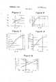
- FIG. 4is a graph illustrating the heat transfer performance of a plurality of single-helix internal-ridged tubes which plots the Sieder-Tate-Equation Constant, C, as a function of the Severity Parameter 4);
- FIG. 5is a graph illustrating the heat transfer performance of a plurality of single-helix internal-ridged tubes which plots the Sieder-Tate-Equation Constant, C,, in relation to a function, which includes the ridge cap dimensions of the tube;
- FIG. 6is a graph illustrating the heat transfer performance of single-helix, internal-ridged tubes, expressed as an improvement ratio over a plain tube;
- FIG. 7is a graph illustrating the Pressure Drop characteristics of single-helix internal-ridged tubes taken at an arbitrary reference Reynolds Number equal to 35,000 as a function of Severity Parameter, (b;
- FIG. 8is a graph illustrating the effect of helix pitch on outside tube diameter when internal single-start helical ridges are formed by an external corrugating operation.
- FIG. 9is a graph illustrating a correlation of helix pitch reguired for a uniform diameter corrugated tube with the product of the outside diameter and the wall thickness.
- FIG. 1shows a corrugated tube indicated generally at 10 having a plain end 12 and a corrugated section 14.
- the outer diameter A? of the plain end 12is preferably equal to or very slightly greater than the outer diameter CT) of the corrugated section 14 while the plain end wall thickness E is equal to the corrugated section wall thickness (T.
- the distance GE between identical points on adjacent internal ridges produced by the corrugationsis defined as the pitch p.
- the internal corrugationscomprise ridge portions indicated generally at 20 and connecting portions indicated generally at 22.
- the ridge portion 20is generally convex toward the inside of the tube while the connecting portion 22 is generally concave.
- the portions 20 and 22join each other smoothly at points of inflection 26 where the ridge arc 20' and the connecting are 22' have a common tangent.
- the convex curved portion 27 of the ridge 20 between the points 26is termed the ridge cap.
- the ridge caphas a width between points 26, 26 defined as t and a height y between its crest 28 and points 26.
- the ridge height 2is the radial distance between ridge crest 28 and the outermost point 30 on the inner surface of connecting portion 22.
- the internal diameter dis the diametral distance between points 30 on opposite sides of the tube.
- the pitch, pis the distance between any pair of identical points on adjacent ridges 20, such as the points 28.
- FIG. 3illustrates a modification of the tube shown in FIGS. 1 and 2 in that connecting portions 122 are altered in shape as compared to the concave connecting portions 22 of FIG. 2.
- the connecting portion 122is flat over a portion 34 of its length.
- the outer surface of the tubeis broken away in FIG. to illustrate the fact that the tube could have a number of different outer surface configurations other than the shape shown in FIG. 2. Since our invention is concerned with improving the tube side heat transfer properties, there is no need to discuss particular external shapes since these will depend on the external heat transfer conditions.
- FIG. 4is a plot of the data derived from testing a plain tube and many single-helix internally ridged tubes using the modified Wilson plot technique previously referenced to determine the value of the Sieder-Tate Equation constant C,.
- the abcissa of the plotis the severity parameter d) which is equal to e/;; d, where e is the height of the corrugations (FIG. 2), p is the pitch and d, is the internal diameter.
- the parameter d)is defined as a severity parameter since it is strongly dependent on the ridge height or severity of the corrugations. From the curve 36 it can be seen that C, reaches a peak value when d) 0.365 X 10 and then drops off as 4; increases.
- the right hand portion of the curve 36represents several prior art tubes.
- Point 38represents the l in. tube and point 40 represents the 5/8 in. tube discussed in the aforementioned Withers and Young article.
- the single-helix ridged tubes testedrepresent variations in ridge height depth e from 0.0l40.046 in.
- pitch pfrom 0.240-0.625 and internal diameter d, from 0.530-l .288 in. These values are not meant to be limiting, however, since it is felt that e could be at least as large as 0.09 in., the pitch p at least as great as 1.2 in. and the internal diameter d, any value up to about 3 inches.
- FIG. 6is a plot similar to FIG. 4 except that it relates, by curve 50, the improvement ratio over plain tube [C i/ (C 01?] to the d) parameter.
- This alternative method of displaying the C vs 41 correlationis useful in comparing results from different laboratories since the base value, (C i)p, for plain tube may vary somewhat among different test setups.
- FIG. 7illustrates a correlation of pressure drop characteristics of single-helix, internal-ridge tubes as a function of the severity parameter 4; where the pressure drop is expressed as Friction Factor, f, at a reference Reynolds number of 35,000. It is commonly understood that the friction factor, f, is a direct index of pressure drop per unit length of tube, as long as one compares tubes of a given diameter at the same Reynolds number. Since it is evident from the curve 56 of FIG. 7 that pressure drop increases significantly with increases in the severity parameter qb, it is desirable that tubes be configured so that 4: not be permitted to increase beyond the optimum value of 0.365 X 10'. Such an increase in (1) would not only result in a lower value of C,, but would also cause a presumably undesirable increase in pressure drop.
- FIG. 8illustrates the effect of the helix pitch, p, on the outside diameter of a corrugated tube when internal single-start helical ridges are formed by an external corrugating operation of the type shown in Anderson U.S. Pat. No. 3,128,821.
- the curve 58shows that by varying the pitch, p, the outside diameter G (FIG. 2)
- the curve 58is obtained for any particular alloy, diameter and wall thickness by arbitrarily selecting a given corrugation depth, corrugating the tube at various helix angles, and measuring the resulting outer diameter and corresponding pitch for each of the helix angles. By connecting the test points with a curve as shown in FIG. 8, the pitch required to provide a uniform diameter can be readily determined.
- FIG. 9is a graph illustrating the helical pitch required to obtain a uniform diameter corrugated tube for any particular product of the tube outside diameter times its wall thickness.
- the particular correlation curve 60 shownwas determined from data derived from a given tube material (l0 cupronickel) and given groove depth (0.032 in.) where the tube was corrugated in a single helix style by apparatus such as shown in Anderson U.S. Pat. No. 3,128,821. A family of such curves could be determined for other tube materials and groove depths.
- the correlationis possible since experiments have shown that there exists a certain helix pitch, (p),, which will yield a uniform diameter product in the sense that the maximum projected outer diameter of the corrugated section is essentially equal to the outside diameter of the plain starting tube.
- teachings of the present invention relative to designing tubes for maximum internal heat transferare applicable to any of the common tube materials such as cuprous alloys, titanium, stainless steel, carbon steel and aluminum and are independent of outside diameter and the outer configuration of the tube.
- the metal heat transfer tube of claim 1 wherein the helical ridgehas a convex ridge cap, the axial thickness t of said cap being equal to or greater than 0.085 inches.
Landscapes
- Engineering & Computer Science (AREA)
- Physics & Mathematics (AREA)
- Mechanical Engineering (AREA)
- Geometry (AREA)
- Thermal Sciences (AREA)
- General Engineering & Computer Science (AREA)
- Heat-Exchange Devices With Radiators And Conduit Assemblies (AREA)
- Heat Treatment Of Articles (AREA)
- Rigid Pipes And Flexible Pipes (AREA)
Abstract
Description
Claims (8)
Applications Claiming Priority (1)
| Application Number | Priority Date | Filing Date | Title |
|---|---|---|---|
| US23257172A | 1972-03-07 | 1972-03-07 |
Publications (1)
| Publication Number | Publication Date |
|---|---|
| US3779312Atrue US3779312A (en) | 1973-12-18 |
Family
ID=22873680
Family Applications (1)
| Application Number | Title | Priority Date | Filing Date |
|---|---|---|---|
| US00232571AExpired - LifetimeUS3779312A (en) | 1972-03-07 | 1972-03-07 | Internally ridged heat transfer tube |
Country Status (16)
| Country | Link |
|---|---|
| US (1) | US3779312A (en) |
| JP (1) | JPS5641915B2 (en) |
| AR (1) | AR196754A1 (en) |
| AT (1) | AT329608B (en) |
| AU (1) | AU469249B2 (en) |
| BR (1) | BR7301661D0 (en) |
| CA (1) | CA968342A (en) |
| CH (1) | CH564752A5 (en) |
| DE (1) | DE2310315B2 (en) |
| EG (1) | EG10775A (en) |
| ES (1) | ES214248Y (en) |
| FR (1) | FR2174872B1 (en) |
| GB (1) | GB1418113A (en) |
| IL (1) | IL41446A (en) |
| IT (1) | IT977286B (en) |
| ZA (1) | ZA73737B (en) |
Cited By (43)
| Publication number | Priority date | Publication date | Assignee | Title |
|---|---|---|---|---|
| JPS5169164U (en)* | 1974-11-27 | 1976-06-01 | ||
| US4007774A (en)* | 1975-09-23 | 1977-02-15 | Uop Inc. | Heat exchange apparatus and method of controlling fouling therein |
| FR2374610A1 (en)* | 1976-12-15 | 1978-07-13 | Gen Atomic Co | HELICOIDAL RIBBON TUBE FOR HEAT EXCHANGES AND ITS MANUFACTURING PROCESS |
| DE3007380A1 (en)* | 1979-02-27 | 1980-09-04 | Gen Atomic Co | HEAT TRANSFER TUBES |
| US4228852A (en)* | 1979-02-28 | 1980-10-21 | Akira Togashi | Tubular body |
| US4245697A (en)* | 1976-05-24 | 1981-01-20 | Akira Togashi | Tubular body |
| US4305460A (en)* | 1979-02-27 | 1981-12-15 | General Atomic Company | Heat transfer tube |
| US4330036A (en)* | 1980-08-21 | 1982-05-18 | Kobe Steel, Ltd. | Construction of a heat transfer wall and heat transfer pipe and method of producing heat transfer pipe |
| US4332294A (en)* | 1978-04-06 | 1982-06-01 | Metallgesellschaft Aktiengesellschaft | Gas cooler with multiply deformed lead tubes |
| US4583389A (en)* | 1978-08-28 | 1986-04-22 | Ltv Steel | Method for removing certain of the corrugations in a helically corrugated pipe |
| US4658892A (en)* | 1983-12-28 | 1987-04-21 | Hitachi Cable, Ltd. | Heat-transfer tubes with grooved inner surface |
| US4679544A (en)* | 1983-11-04 | 1987-07-14 | Modern Home Products Corp. | Threaded adjustable gas intake assembly |
| US4685292A (en)* | 1985-09-09 | 1987-08-11 | Zwick Energy Research Organization, Inc. | Exhaust cooling system for internal combustion engine |
| US4690211A (en)* | 1984-06-20 | 1987-09-01 | Hitachi, Ltd. | Heat transfer tube for single phase flow |
| US4773384A (en)* | 1983-11-04 | 1988-09-27 | Modern Home Products Corp. | Adjustable gas intake assembly |
| US5271376A (en)* | 1991-08-12 | 1993-12-21 | Rheem Manufacturing Company | Serpentined tubular heat exchanger apparatus for a fuel-fired forced air heating furnace |
| US5590711A (en)* | 1993-12-14 | 1997-01-07 | Kabushiki Kaisha Kobe Seiko Sho | Heat transfer tube for absorber |
| US5655599A (en)* | 1995-06-21 | 1997-08-12 | Gas Research Institute | Radiant tubes having internal fins |
| US5680772A (en)* | 1995-11-29 | 1997-10-28 | Sanyo Electric Co., Ltd. | Absorption type refrigerating machine |
| US5697430A (en)* | 1995-04-04 | 1997-12-16 | Wolverine Tube, Inc. | Heat transfer tubes and methods of fabrication thereof |
| US5979548A (en)* | 1996-12-23 | 1999-11-09 | Fafco, Inc. | Heat exchanger having heat exchange tubes with angled heat-exchange performance-improving indentations |
| US7017651B1 (en)* | 2000-09-13 | 2006-03-28 | Raytheon Company | Method and apparatus for temperature gradient control in an electronic system |
| US20060201568A1 (en)* | 2002-11-18 | 2006-09-14 | Henry Petersen | Flexible, tubular device e.g. a bellows |
| US20070028984A1 (en)* | 2003-03-18 | 2007-02-08 | Imperial College Innovations Limited | Helical piping |
| EP1793188A1 (en)* | 2005-12-05 | 2007-06-06 | GEA Ibérica S.A. | Surface condenser |
| US20080017550A1 (en)* | 2004-09-21 | 2008-01-24 | Caro Colin G | Piping |
| US20080257436A1 (en)* | 2004-09-21 | 2008-10-23 | Caro Colin G | Piping |
| US20090013676A1 (en)* | 2007-07-11 | 2009-01-15 | Andreas Capelle | Lightweight flow heat exchanger |
| US20090014151A1 (en)* | 2007-07-11 | 2009-01-15 | Andreas Capelle | Exhaust gas heat exchanger with an oscillationattenuated bundle of exchanger tubes |
| US20090250198A1 (en)* | 2006-09-08 | 2009-10-08 | Tsinghua University | Hot water corrugated heat transfer tube |
| US20100218912A1 (en)* | 2008-04-07 | 2010-09-02 | Lane Lawless | Method, apparatus, header, and composition for ground heat exchange |
| US20110174469A1 (en)* | 2010-01-15 | 2011-07-21 | Kim Hongseong | Double-pipe heat exchanger |
| US8029749B2 (en) | 2004-09-21 | 2011-10-04 | Technip France S.A.S. | Cracking furnace |
| US20120060727A1 (en)* | 2009-03-17 | 2012-03-15 | ToTAL PETROCHECMICALS RESEARCH FELUY | Process for quenching the effluent gas of a furnace |
| US8162040B2 (en) | 2006-03-10 | 2012-04-24 | Spinworks, LLC | Heat exchanging insert and method for fabricating same |
| US8354084B2 (en) | 2008-09-19 | 2013-01-15 | Technip France S.A.S. | Cracking furnace |
| US9121630B1 (en) | 2008-04-07 | 2015-09-01 | Rygan Corp. | Method, apparatus, conduit, and composition for low thermal resistance ground heat exchange |
| US20150294764A1 (en)* | 2012-12-25 | 2015-10-15 | Yazaki Corporation | Wire harness |
| US20150362174A1 (en)* | 2014-06-17 | 2015-12-17 | Doosan Heavy Industries Construction Co., Ltd. | Transfer pipe for furnace |
| US9885523B2 (en) | 2013-03-15 | 2018-02-06 | Caloris Engineering, LLC | Liquid to liquid multi-pass countercurrent heat exchanger |
| US20180104731A1 (en)* | 2015-03-12 | 2018-04-19 | Jfe Steel Corporation | Steel pipe, steel pipe structure, method of manufacturing steel pipe, and method of designing steel pipe |
| US11493282B2 (en)* | 2016-08-05 | 2022-11-08 | Obshestvo S Ogranichennoi Otvetstvennost'u “Reinnolts Lab” | Shell and tube condenser and the heat exchange tube of a shell and tube condenser (variants) |
| US11542440B2 (en)* | 2019-05-31 | 2023-01-03 | Centre National De La Recherche Scientifique | Tube for a steam cracking furnace having a segment with an elliptical or lobed cross section |
Families Citing this family (8)
| Publication number | Priority date | Publication date | Assignee | Title |
|---|---|---|---|---|
| JPS5132456U (en)* | 1974-08-31 | 1976-03-10 | ||
| JPS5238663A (en)* | 1975-09-22 | 1977-03-25 | Hitachi Ltd | Heat transmission tube |
| JPS5514956Y2 (en)* | 1978-05-04 | 1980-04-05 | ||
| JPS5526706Y2 (en)* | 1978-12-13 | 1980-06-26 | ||
| DE102006004704A1 (en)* | 2006-01-31 | 2007-08-09 | BRÜNDERMANN, Georg | Method for optimizing waste heat boilers |
| DE102008030423B4 (en) | 2007-12-05 | 2016-03-03 | GIB - Gesellschaft für Innovation im Bauwesen mbH | Pipe with a surface profile-modified outer surface by pimples |
| JP6223298B2 (en)* | 2014-07-31 | 2017-11-01 | 株式会社コベルコ マテリアル銅管 | Heat transfer tube for single-phase flow in tube |
| DE102018204746A1 (en)* | 2018-03-28 | 2019-10-02 | Hanon Systems | exhaust gas cooler |
Citations (1)
| Publication number | Priority date | Publication date | Assignee | Title |
|---|---|---|---|---|
| US3612175A (en)* | 1969-07-01 | 1971-10-12 | Olin Corp | Corrugated metal tubing |
Family Cites Families (3)
| Publication number | Priority date | Publication date | Assignee | Title |
|---|---|---|---|---|
| US3088494A (en)* | 1959-12-28 | 1963-05-07 | Babcock & Wilcox Co | Ribbed vapor generating tubes |
| US3213525A (en)* | 1961-02-10 | 1965-10-26 | Babcock & Wilcox Co | Method of forming an internal rib in the bore of a tube |
| US3217799A (en)* | 1962-03-26 | 1965-11-16 | Calumet & Hecla | Steam condenser of the water tube type |
- 1972
- 1972-03-07USUS00232571Apatent/US3779312A/ennot_activeExpired - Lifetime
- 1973
- 1973-01-29CACA162,276Apatent/CA968342A/ennot_activeExpired
- 1973-02-01ZAZA730737Apatent/ZA73737B/enunknown
- 1973-02-01ILIL41446Apatent/IL41446A/enunknown
- 1973-02-02AUAU51715/73Apatent/AU469249B2/ennot_activeExpired
- 1973-02-09ITIT7348173Apatent/IT977286B/enactive
- 1973-02-22JPJP2072073Apatent/JPS5641915B2/janot_activeExpired
- 1973-02-27ATAT175473Apatent/AT329608B/ennot_activeIP Right Cessation
- 1973-02-28ARAR246868Apatent/AR196754A1/enactive
- 1973-02-28FRFR7307041Apatent/FR2174872B1/frnot_activeExpired
- 1973-02-28ESES1973214248Upatent/ES214248Y/ennot_activeExpired
- 1973-03-01DEDE2310315Apatent/DE2310315B2/enactiveGranted
- 1973-03-01CHCH305073Apatent/CH564752A5/xxnot_activeIP Right Cessation
- 1973-03-05EGEG80/73Apatent/EG10775A/enactive
- 1973-03-06GBGB1070873Apatent/GB1418113A/ennot_activeExpired
- 1973-03-07BRBR731661Apatent/BR7301661D0/enunknown
Patent Citations (1)
| Publication number | Priority date | Publication date | Assignee | Title |
|---|---|---|---|---|
| US3612175A (en)* | 1969-07-01 | 1971-10-12 | Olin Corp | Corrugated metal tubing |
Cited By (52)
| Publication number | Priority date | Publication date | Assignee | Title |
|---|---|---|---|---|
| JPS5169164U (en)* | 1974-11-27 | 1976-06-01 | ||
| US4007774A (en)* | 1975-09-23 | 1977-02-15 | Uop Inc. | Heat exchange apparatus and method of controlling fouling therein |
| US4245697A (en)* | 1976-05-24 | 1981-01-20 | Akira Togashi | Tubular body |
| FR2374610A1 (en)* | 1976-12-15 | 1978-07-13 | Gen Atomic Co | HELICOIDAL RIBBON TUBE FOR HEAT EXCHANGES AND ITS MANUFACTURING PROCESS |
| US4332294A (en)* | 1978-04-06 | 1982-06-01 | Metallgesellschaft Aktiengesellschaft | Gas cooler with multiply deformed lead tubes |
| US4583389A (en)* | 1978-08-28 | 1986-04-22 | Ltv Steel | Method for removing certain of the corrugations in a helically corrugated pipe |
| DE3007380A1 (en)* | 1979-02-27 | 1980-09-04 | Gen Atomic Co | HEAT TRANSFER TUBES |
| US4305460A (en)* | 1979-02-27 | 1981-12-15 | General Atomic Company | Heat transfer tube |
| US4228852A (en)* | 1979-02-28 | 1980-10-21 | Akira Togashi | Tubular body |
| US4330036A (en)* | 1980-08-21 | 1982-05-18 | Kobe Steel, Ltd. | Construction of a heat transfer wall and heat transfer pipe and method of producing heat transfer pipe |
| US4679544A (en)* | 1983-11-04 | 1987-07-14 | Modern Home Products Corp. | Threaded adjustable gas intake assembly |
| US4773384A (en)* | 1983-11-04 | 1988-09-27 | Modern Home Products Corp. | Adjustable gas intake assembly |
| US4658892A (en)* | 1983-12-28 | 1987-04-21 | Hitachi Cable, Ltd. | Heat-transfer tubes with grooved inner surface |
| US4690211A (en)* | 1984-06-20 | 1987-09-01 | Hitachi, Ltd. | Heat transfer tube for single phase flow |
| US4685292A (en)* | 1985-09-09 | 1987-08-11 | Zwick Energy Research Organization, Inc. | Exhaust cooling system for internal combustion engine |
| US5271376A (en)* | 1991-08-12 | 1993-12-21 | Rheem Manufacturing Company | Serpentined tubular heat exchanger apparatus for a fuel-fired forced air heating furnace |
| US5590711A (en)* | 1993-12-14 | 1997-01-07 | Kabushiki Kaisha Kobe Seiko Sho | Heat transfer tube for absorber |
| US5697430A (en)* | 1995-04-04 | 1997-12-16 | Wolverine Tube, Inc. | Heat transfer tubes and methods of fabrication thereof |
| US5655599A (en)* | 1995-06-21 | 1997-08-12 | Gas Research Institute | Radiant tubes having internal fins |
| US5680772A (en)* | 1995-11-29 | 1997-10-28 | Sanyo Electric Co., Ltd. | Absorption type refrigerating machine |
| US5979548A (en)* | 1996-12-23 | 1999-11-09 | Fafco, Inc. | Heat exchanger having heat exchange tubes with angled heat-exchange performance-improving indentations |
| US7017651B1 (en)* | 2000-09-13 | 2006-03-28 | Raytheon Company | Method and apparatus for temperature gradient control in an electronic system |
| US20060201568A1 (en)* | 2002-11-18 | 2006-09-14 | Henry Petersen | Flexible, tubular device e.g. a bellows |
| US7334609B2 (en)* | 2002-11-18 | 2008-02-26 | Norsk Hydro Asa | Flexible tubular device |
| US20070028984A1 (en)* | 2003-03-18 | 2007-02-08 | Imperial College Innovations Limited | Helical piping |
| US20080017550A1 (en)* | 2004-09-21 | 2008-01-24 | Caro Colin G | Piping |
| US20080257436A1 (en)* | 2004-09-21 | 2008-10-23 | Caro Colin G | Piping |
| US7749462B2 (en)* | 2004-09-21 | 2010-07-06 | Technip France S.A.S. | Piping |
| US8029749B2 (en) | 2004-09-21 | 2011-10-04 | Technip France S.A.S. | Cracking furnace |
| US8088345B2 (en) | 2004-09-21 | 2012-01-03 | Technip France S.A.S. | Olefin production furnace having a furnace coil |
| USRE43650E1 (en) | 2004-09-21 | 2012-09-11 | Technip France S.A.S. | Piping |
| EP1793188A1 (en)* | 2005-12-05 | 2007-06-06 | GEA Ibérica S.A. | Surface condenser |
| US8162040B2 (en) | 2006-03-10 | 2012-04-24 | Spinworks, LLC | Heat exchanging insert and method for fabricating same |
| US20090250198A1 (en)* | 2006-09-08 | 2009-10-08 | Tsinghua University | Hot water corrugated heat transfer tube |
| US20090013676A1 (en)* | 2007-07-11 | 2009-01-15 | Andreas Capelle | Lightweight flow heat exchanger |
| US20090014151A1 (en)* | 2007-07-11 | 2009-01-15 | Andreas Capelle | Exhaust gas heat exchanger with an oscillationattenuated bundle of exchanger tubes |
| US8387684B2 (en)* | 2007-07-11 | 2013-03-05 | Visteon Global Technologies, Inc. | Exhaust gas heat exchanger with an oscillationattenuated bundle of exchanger tubes |
| US20100218912A1 (en)* | 2008-04-07 | 2010-09-02 | Lane Lawless | Method, apparatus, header, and composition for ground heat exchange |
| US9121630B1 (en) | 2008-04-07 | 2015-09-01 | Rygan Corp. | Method, apparatus, conduit, and composition for low thermal resistance ground heat exchange |
| US9816023B2 (en)* | 2008-04-07 | 2017-11-14 | Rygan Corp | Method, apparatus, header, and composition for ground heat exchange |
| US8354084B2 (en) | 2008-09-19 | 2013-01-15 | Technip France S.A.S. | Cracking furnace |
| US20120060727A1 (en)* | 2009-03-17 | 2012-03-15 | ToTAL PETROCHECMICALS RESEARCH FELUY | Process for quenching the effluent gas of a furnace |
| US20110174469A1 (en)* | 2010-01-15 | 2011-07-21 | Kim Hongseong | Double-pipe heat exchanger |
| US9627102B2 (en)* | 2012-12-25 | 2017-04-18 | Yazaki Corporation | Wire harness |
| US20150294764A1 (en)* | 2012-12-25 | 2015-10-15 | Yazaki Corporation | Wire harness |
| US9885523B2 (en) | 2013-03-15 | 2018-02-06 | Caloris Engineering, LLC | Liquid to liquid multi-pass countercurrent heat exchanger |
| US20150362174A1 (en)* | 2014-06-17 | 2015-12-17 | Doosan Heavy Industries Construction Co., Ltd. | Transfer pipe for furnace |
| US10274193B2 (en)* | 2014-06-17 | 2019-04-30 | DOOSAN Heavy Industries Construction Co., LTD | Transfer pipe for furnace |
| US20180104731A1 (en)* | 2015-03-12 | 2018-04-19 | Jfe Steel Corporation | Steel pipe, steel pipe structure, method of manufacturing steel pipe, and method of designing steel pipe |
| US10189065B2 (en)* | 2015-03-12 | 2019-01-29 | Jfe Steel Corporation | Steel pipe, steel pipe structure, method of manufacturing steel pipe, and method of designing steel pipe |
| US11493282B2 (en)* | 2016-08-05 | 2022-11-08 | Obshestvo S Ogranichennoi Otvetstvennost'u “Reinnolts Lab” | Shell and tube condenser and the heat exchange tube of a shell and tube condenser (variants) |
| US11542440B2 (en)* | 2019-05-31 | 2023-01-03 | Centre National De La Recherche Scientifique | Tube for a steam cracking furnace having a segment with an elliptical or lobed cross section |
Also Published As
| Publication number | Publication date |
|---|---|
| IT977286B (en) | 1974-09-10 |
| JPS5641915B2 (en) | 1981-10-01 |
| GB1418113A (en) | 1975-12-17 |
| IL41446A (en) | 1975-06-25 |
| DE2310315C3 (en) | 1979-07-26 |
| ATA175473A (en) | 1975-08-15 |
| EG10775A (en) | 1976-05-31 |
| FR2174872A1 (en) | 1973-10-19 |
| JPS48101642A (en) | 1973-12-21 |
| FR2174872B1 (en) | 1976-04-30 |
| DE2310315A1 (en) | 1973-09-13 |
| BR7301661D0 (en) | 1974-05-16 |
| CA968342A (en) | 1975-05-27 |
| DE2310315B2 (en) | 1978-11-16 |
| AR196754A1 (en) | 1974-02-19 |
| AU469249B2 (en) | 1976-02-05 |
| ES214248U (en) | 1976-07-01 |
| CH564752A5 (en) | 1975-07-31 |
| AT329608B (en) | 1976-05-25 |
| ZA73737B (en) | 1973-11-28 |
| AU5171573A (en) | 1974-08-08 |
| IL41446A0 (en) | 1973-04-30 |
| ES214248Y (en) | 1976-12-01 |
Similar Documents
| Publication | Publication Date | Title |
|---|---|---|
| US3779312A (en) | Internally ridged heat transfer tube | |
| Vicente et al. | Experimental investigation on heat transfer and frictional characteristics of spirally corrugated tubes in turbulent flow at different Prandtl numbers | |
| US2960114A (en) | Innerfinned heat transfer tubes | |
| US11835302B2 (en) | Tubeless heat exchanger for fluid heating systems | |
| US4305460A (en) | Heat transfer tube | |
| US10024607B2 (en) | Heat exchanger tube and methods for producing a heat exchanger tube | |
| US3467180A (en) | Method of making a composite heat-exchanger tube | |
| US3662582A (en) | Heat-exchange tubing and method of making it | |
| US3750709A (en) | Heat-exchange tubing and method of making it | |
| US3407874A (en) | Fin tube assemblage for heat exchangers | |
| US5690167A (en) | Inner ribbed tube of hard metal and method | |
| KR960001709A (en) | Metal fin tube | |
| US2735698A (en) | Header plate-tube joint for heat- | |
| Córcoles et al. | Influence of corrugation shape on heat transfer performance in corrugated tubes using numerical simulations | |
| US4086959A (en) | Automotive oil cooler | |
| US4040479A (en) | Finned tubing having enhanced nucleate boiling surface | |
| JPS5924311B2 (en) | Heat transfer tube with multiple internal ridges | |
| JP2005526945A (en) | Reversible grooved tube for heat exchanger | |
| KR20100123599A (en) | Metal heat exchanger tube | |
| US3762468A (en) | Heat transfer members | |
| US2990163A (en) | Turbulizer | |
| US1909005A (en) | Method of making corrugated wall tubing | |
| US3200848A (en) | Heat exchanger tubes | |
| JP2009174833A (en) | Heat exchanger tube for heat exchanger and heat exchanger using the same | |
| US2586653A (en) | Method of producing heat exchange elements |
Legal Events
| Date | Code | Title | Description |
|---|---|---|---|
| STCF | Information on status: patent grant | Free format text:PATENTED FILE - (OLD CASE ADDED FOR FILE TRACKING PURPOSES) | |
| AS | Assignment | Owner name:WOLVERINE TUBE, INC., A DE. CORP.,ALABAMA Free format text:ASSIGNMENT OF ASSIGNORS INTEREST;ASSIGNOR:UOP INC.,;REEL/FRAME:004657/0711 Effective date:19861027 Owner name:WOLVERINE TUBE, INC., 2100 MARKET STREET, N.E., DE Free format text:ASSIGNMENT OF ASSIGNORS INTEREST.;ASSIGNOR:UOP INC.,;REEL/FRAME:004657/0711 Effective date:19861027 | |
| AS | Assignment | Owner name:BANK OF NOVA SCOTIA, THE, 44 KING STREET, WEST, TO Free format text:ASSIGNMENT OF ASSIGNORS INTEREST.;ASSIGNOR:WOLVERINE ACQUISITION CORP. A CORP. OF DE;REEL/FRAME:004696/0897 Effective date:19870313 | |
| AS | Assignment | Owner name:WOLVERINE ACQUISITION CORP., A DE CORP,DELAWARE Free format text:ASSIGNMENT OF ASSIGNORS INTEREST;ASSIGNOR:WOLVERINE TUBE, INC.,;REEL/FRAME:004728/0083 Effective date:19870318 Owner name:WOLVERINE ACQUISITION CORP., CORPORATION TRUST CEN Free format text:ASSIGNMENT OF ASSIGNORS INTEREST.;ASSIGNOR:WOLVERINE TUBE, INC.,;REEL/FRAME:004728/0083 Effective date:19870318 | |
| AS | Assignment | Owner name:WOLVERINE TUBE, INC., A CORP. OF AL,ALABAMA Free format text:CHANGE OF NAME;ASSIGNOR:WOLVERINE ACQUISITION CORP.;REEL/FRAME:004827/0237 Effective date:19870626 Owner name:WOLVERINE TUBE, INC., A CORP. OF AL Free format text:CHANGE OF NAME;ASSIGNOR:WOLVERINE ACQUISITION CORP.;REEL/FRAME:004827/0237 Effective date:19870626 |