US3777430A - Complementary mating elements for double-skin foam core panel - Google Patents
Complementary mating elements for double-skin foam core panelDownload PDFInfo
- Publication number
- US3777430A US3777430AUS00285060AUS3777430DAUS3777430AUS 3777430 AUS3777430 AUS 3777430AUS 00285060 AUS00285060 AUS 00285060AUS 3777430D AUS3777430D AUS 3777430DAUS 3777430 AUS3777430 AUS 3777430A
- Authority
- US
- United States
- Prior art keywords
- panels
- facing sheet
- recess
- panel
- central web
- Prior art date
- Legal status (The legal status is an assumption and is not a legal conclusion. Google has not performed a legal analysis and makes no representation as to the accuracy of the status listed.)
- Expired - Lifetime
Links
Images

Classifications
- E—FIXED CONSTRUCTIONS
- E04—BUILDING
- E04F—FINISHING WORK ON BUILDINGS, e.g. STAIRS, FLOORS
- E04F13/00—Coverings or linings, e.g. for walls or ceilings
- E04F13/07—Coverings or linings, e.g. for walls or ceilings composed of covering or lining elements; Sub-structures therefor; Fastening means therefor
- E04F13/08—Coverings or linings, e.g. for walls or ceilings composed of covering or lining elements; Sub-structures therefor; Fastening means therefor composed of a plurality of similar covering or lining elements
- E04F13/0875—Coverings or linings, e.g. for walls or ceilings composed of covering or lining elements; Sub-structures therefor; Fastening means therefor composed of a plurality of similar covering or lining elements having a basic insulating layer and at least one covering layer
- E04F13/0878—Coverings or linings, e.g. for walls or ceilings composed of covering or lining elements; Sub-structures therefor; Fastening means therefor composed of a plurality of similar covering or lining elements having a basic insulating layer and at least one covering layer the basic insulating layer comprising mutual alignment or interlocking means
- E—FIXED CONSTRUCTIONS
- E04—BUILDING
- E04C—STRUCTURAL ELEMENTS; BUILDING MATERIALS
- E04C2/00—Building elements of relatively thin form for the construction of parts of buildings, e.g. sheet materials, slabs, or panels
- E04C2/02—Building elements of relatively thin form for the construction of parts of buildings, e.g. sheet materials, slabs, or panels characterised by specified materials
- E04C2/26—Building elements of relatively thin form for the construction of parts of buildings, e.g. sheet materials, slabs, or panels characterised by specified materials composed of materials covered by two or more of groups E04C2/04, E04C2/08, E04C2/10 or of materials covered by one of these groups with a material not specified in one of the groups
- E04C2/284—Building elements of relatively thin form for the construction of parts of buildings, e.g. sheet materials, slabs, or panels characterised by specified materials composed of materials covered by two or more of groups E04C2/04, E04C2/08, E04C2/10 or of materials covered by one of these groups with a material not specified in one of the groups at least one of the materials being insulating
- E04C2/292—Building elements of relatively thin form for the construction of parts of buildings, e.g. sheet materials, slabs, or panels characterised by specified materials composed of materials covered by two or more of groups E04C2/04, E04C2/08, E04C2/10 or of materials covered by one of these groups with a material not specified in one of the groups at least one of the materials being insulating composed of insulating material and sheet metal
Definitions
- ABSTRACTA double-skin building construction panel having a [73] Assignee:
- This inventionrelates to double-skin foam core building construction panels of the type erected without externally visible fasteners, and more particularly to improvements in complementary mating elements formed in at least the outer facing sheets of such building construction panels.
- Double-skin building construction panels having no lateral adjustment capability and which are erected without externally visible fastenersare known in the prior art for use in the construction of buildings, see U.S. Pat. Nos. 3,290,845 (SNYDER, Dec. 13, 1966), 3,535,844 (GLAROS, Oct. 27, 1970); 3,667,180 (TIS- CHUK, June 6, 1972).
- Double-skin building construction panels having some lateral adjustment capability and which are erected without externally visible fastenersalso are known in the prior art, see U.S. Pat. No. 3,372,520 (HENSEL, Mar. 12, 1968).
- the SNYDER, GLAROS and TISCHUK panelsrequire extensive field cutting and fitting to conform the lateral coverage of the panels with that dictated by the structural-framework.
- the HENSEL arrangementrequires the use of specially shaped, slotted and apertured subgirts in combination with a special clamping plate and fastener to achieve erection and lateral adjustment of the panels.
- the erection and lateral adjustmentrequire the cooperative effort of workmen positioned exteriorly and interiorly of the building framework.
- the principal object of this inventionis to provide an improved laterally adjustable weather-tight joint between double-skin foam core building construction panels.
- Another object of this inventionis to provide improved complementary mating elements for at least the outer facing sheet of a double-skin foam core building construction panel, which mating elements permit the panels to be gathered or spread apart thereby to conform the lateral coverage of the panels with that required by the structural framework.
- Still another object of this inventionis to provide improved complementary mating elements which permit lateral adjustment of the position of each panel relative to a previously erected panel without impairing the weather seal.
- each of the facing sheetsincludes a central web, first and second side walls extending along the opposite side edges of the central web and a flange extending outwardly from the second side wall generally parallel to the central web.
- the facing sheetsare assembled such that the flange of each facing sheet confronts the opposing central web of the other facing sheet and is laterally spaced-apart from the first side wall of the other facing sheet.
- connecting means formed in the first and second side walls of the outer facing sheetprovide a positive mechanical connection between the outer facing sheets of adjacent panels.
- the connecting meansin the form of a recess and a complementary tongue, are arranged such that the position of each panel relative to the previously erected panel may be adjusted laterally, whereby the lateral coverage provided by all of the panels is conformed with that required by the lateral dimensions of the building structural framework.
- the recessis formed integrally with the second side wall of the outer facing sheet and is spaced-apart from both the central web and the flange.
- the recesshaving a generally U-shaped configuration, presents confronting first and second interior wall segments extending generally parallel with the central web, and a connecting wall segment.
- the complementary tongueis formed integrally with the first side wall of the outer facing sheet and extends outwardly therefrom into the recess of the adjacent facing sheet.
- the complementary tonguecomprises a first exterior wall segment which is generally parallel with the first interior wall segment of the recess.
- a second exterior wall segmentadjoins the first exterior wall segment to provide a leading edge remote from the first side wall.
- the second exterior wall segment of the tongueforms an acute angle with the first exterior wall segment.
- a sealant in the fOlIl'l of a bead of caulking material or a sealant strip formed from a soft, closed cell plastic or sponge rubber,is introduced into the recess at a location wherein the sealant is penetrated by the leading edge of the adjacent facing sheet to provide a weather-tight seal.
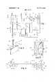
- FIG. 1is a fragmentary elevation view of the present building wall panels erected on a building structural framework
- FIG. 2is a cross-sectional view taken along the line 22 of FIG. 1, illustrating the transverse profile of the present building construction panel;
- FIG. 3is an exploded, isometric view of clip and fastener means
- FIG. 4is a fragmentary cross-sectional view taken along the line 4-4 of FIG. 1;
- FIG. 5is an end view illustrating the profile of the facing sheets used in the building panel of FIG. 2;
- FIG. 6is a fragmentary cross-sectional view, taken along the line 6--6 of FIG. 1, illustrating the normal joint spacing between adjacent panels;
- FIGS. 7 and 8are fragmentary cross-sectional views, similar to FIG. 6, illustrating the minimum and maximum joint spacing between adjacent building panels;
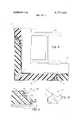
- FIG. 9is a fragmentary cross-sectional view taken along the line 99 of FIG. 1;
- FIG. 10is an isometric view illustrating an alternative sealant strip
- FIG. 11is a fragmentary cross-sectional view similar to the right hand half of FIG. 6, illustrating the sealant strip of FIG. 10 installed in the present panel.
- FIG. 1illustrates a building structural framework 10 of which only vertically spaced horizontal sub-girts 11 and two laterally spaced vertical columns 12a, 12b are illustrated.
- the building structural framework 10supports a wall structure 13.
- the wall structure 13is assembled from plural building panels 14 erected in edge overlapped relation and presenting plural joints 15. Each of the panels 14 is secured to selected ones of the subgirts 11 by clip and fastener means 16.
- Each of the panels 14(FIG. 2) comprises an outer facing sheet 17, an inner facing sheet 18 and a plastic foam core 19 disposed between the facing sheets 17, 18.
- Each of the facing sheets 17, 18includes a central web 20 having first and second side walls 21, 22 provided along the opposite longitudinal edges thereof.
- a flange 23extends outwardly from the second side wall and is generally parallel with the central web 20.
- the facing sheets 17, 18are laterally offset from one another, overall arrangement being such that the flange 23 of each facing sheet 17(18) confronts the opposing central web 20 of the other facing sheet 18(17) and is laterally spaced-apart from the first side wall 21 of the other facing sheet 18(17).
- the panel 14presents an overlapping edge portion 24 and an overlapped edge portion 25.
- a gap 26is presented at each of the edge portions 24, 25 between the flange 23 and the adjacent first side wall 21.
- the foam core 19is exposed at the gaps 26.
- the fastening means 16(FIG. 3) comprises a clip member 27 and a fastener 28.
- the clip member 27includes a first arm 29 provided with central and end apertures 30 and a second arm 31.
- the clip member 27preferably is in the form of an angle wherein the first and second arms 29, 31 are mutually perpendicular.
- the fastener 28preferably is of the self-tapping type.
- each of the facing sheets 17 (18)presents a recess 32 and a complementary tongue 33.
- the recess 32is formed in the second side wall 22 and is spaced-apart from both the central web and the flange 23.
- the recess 32has a generally U-shaped configuration including confronting first and second interior wall segments 34, 35 which extend generally parallel with the central web 20, and a connecting wall segment 36.
- the complementary tongue 33is formed in the first side wall 21 and comprises first and second exterior wall segments 37, 38.
- the first exterior wall segment 37adjoins the first side wall 21 and extends outwardly therefrom generally parallel with the central web 20.
- the second exterior wall segment 38adjoins the first exterior wall segment 37 to provide a leading edge 39 remote from the first wall segment 21.
- the second exterior wall segment 38extends away from the central web 20 and forms an acute angle indicated at 40, with the first exterior wall segment 37.
- the recess 32has an interior height indicated at 41 and that the tongue 33 has an exterior thickness indicated at 42.
- the hidden face 45 of the first exterior wall segment 34 of the recess 32is spaced from the exterior web face 47 at a distance indicated at 43; and that the exposed face 46 of the first exterior wall segment 37 of the tongue 33 is spaced from the exterior web face 47 at a distance indicated at 44.
- the interior height 41 of the recess 32exceeds the thickness 42 of the tongue 33 by 2 to 4 metal thicknesses; and the distance 44 exceeds the distance 43 by l to 2 metal thicknesses.
- the overall arrangementis such that when adjacent panels 14A, 14B (FIG. 6) are assembled to form the joint 15, the tongue 33 of the panel 14B is centered with respect to the recess 32 of the adjacent panel 14A.
- the exposed tongue face 46is spaced apart from the hidden recess face 45.
- a bead 56 of sealant material(FIG. 5) is applied across substantially the entire width and along the entire length of the hidden face 45 of the recess 32.
- FIG. 6illustrates the normal installed position of the adjacent panels 14A, 14B. It will be observed that a space 50 normal joint spacing is presented at the joint 15. However, the dimensions 48 and 49 (FIG. 5) are such that the normal joint spacing 50 can be adjusted between two extremes, that is, wherein no space minimum joint spacing 55 (FIG. 8) is presented at the joint 15; and wherein a maximum joint spacing 51 (FIG. 7) is presented at the joint 15. Thus in accordance with this invention, the position of each panel may be adjusted laterally with respect to that of the previously erected panel prior to securing each panel to the subgirts 11.
- the normal joint spacingis three-thirtysecondth inch; the maximum permissible joint spacing is three-sixteenth inch; and the permissible variation in the joint space from three-thirtysecondth inch is plus or minus threethirtysecondth inch.
- FIG. 5A fragment of a panel 14C is illustrated in dotted outline at the right hand side of FIG. 6. It will be observed that as the tongue 33 of the panel 14C enters the recess 32 of the previously erected panel 148, the leading edge 39 is positioned to engage the sealant bead 56. When the tongue 33 reaches its final position, as shown at the left hand side of FIG. 6, a portion of the sealant head 56 has been displaced from its initial position.
- corner panels 14a, 14bare applied to the vertical columns 12a, 12b.
- the construction and installed position of a typical corner panelis illustrated in FIG. 9.
- the corner panel 14a (14b)has no exposed trim elements and provides an aesthetically pleasing, visual continuity in the appearance of the panels along adjacent building faces.
- the panel 14amay comprise one of the panels 14 which is bent along its longitudinal center line of the facing sheet 17.
- each of the panels 14has a modular width indicated at M, which corresponds to the distance between the first and second side walls 21, 22 (FIG. 5).
- the overall distance indicated at D in FIG. 1Prior to erecting the panels 14, the overall distance indicated at D in FIG. 1, between the corner panels 14a and 14b is determined. If the position of the vertical columns 12a, 12b is in accordance with the engineering drawings, then the panels 14 can be erected at the normal joint spacing 50 (FIG. 6). However, if the distance between the vertical columns 12a, 12b is ei ther less than or greater than that specified, the difference will be reflected in the overall distance D.
- the joint spacingis determined by subtracting from the overall distance D, the product of the number of panels times the modular coverage M. The remainder is then divided by the number ofjoints. Erection of the panels 14 to the desired joint spacing may be accomplished by the aid of gauges 52 of which only one is illustrated in FIGS. 6 and 7.
- the gauge 52has a gauging end 53 adapted to be inserted between the adjacent panels 14a, 14b and a handle 54.
- the gauging end 53may, for example, be provided with one or more strips 55 of predetermined thickness to arrive at the desired joint spacing.
- FIG.illustrates an alternative sealant strip 57 formed from soft polyvinyl chloride or soft silicone rubber preferably of the closed cell type.
- One face of the sealant strip 57is provided with an adhesive coating 58 which is protected by a stripable backing sheet 59.
- the sealant strip 57is installed in the recess 32 of the panel 14D (FIG. 11). When installed, the sealant strip 57 is secured by the adhesive coating 58 (FIG. 10) to the connecting wall segment 36.
- the sealant strip 57also engages the interior face 45 of the first interior wall segment 34 and is thus positioned for engagement by the tongue 33 of the adjacent panel 14E thereby to provide a weather-tight seal.
- each of said panelshaving an outer facing sheet laterally offset from and spacedapart from an inner facing sheet, and a foam core disposed therebetween; each of said facing sheets including a central web, first and second side walls extending along the opposite sides of said central web, and a flange extending outwardly from the second side wallgenerally parallel to said central web, the flange of each facing sheet confronting the opposing central web of the other facing sheet and being laterally spaced-apart from the first side wall of the other facing sheet; said panels being erected (a) with the first side wall of each facing sheet confronting the second side wall of the adjacent facing sheet, and (b) with said flange of each outer facing sheet positioned inboard of and spacedapart from said flange of each said inner facing sheet; and clip and fastener means engageable with the flanges of the outer facing sheets
- each outer facing sheethaving a recess formed integrally therein and sacedapart from said central web and from said flange.
- said recesscomprising confronting first and second interior wall segments extending generally parallel with said central web, and a connecting wall segment; and a complementary tongue formed integrally with said first side wall of each outer facing sheet and extending outwardly therefrom into the recess of the adjacent facing sheet, said complementary tongue comprising a first exterior wall segment confronting said first interior wall segment and being generally parallel therewith, and a second exterior wall segment adjoining said first exterior wall segment to provide a leading edge remote from said first side wall; the width of said complementary tongue and the depth of said recess being such that prior to securing said panels to said subgirts, the position of each panel may be adjusted laterally with respect to the previously erected panel, thereby to conform the lateral coverage provided by all of said panels with that required by said structural framework.
- each said inner facing sheetis provided with a said recess and a said complementary tongue, whereby laterally adjustable positive mechanical connections also are provided between the inner facing sheets of adjacent panels.
Landscapes
- Engineering & Computer Science (AREA)
- Architecture (AREA)
- Civil Engineering (AREA)
- Structural Engineering (AREA)
- Building Environments (AREA)
Abstract
Description
Claims (6)
Applications Claiming Priority (1)
| Application Number | Priority Date | Filing Date | Title |
|---|---|---|---|
| US28506072A | 1972-08-30 | 1972-08-30 |
Publications (1)
| Publication Number | Publication Date |
|---|---|
| US3777430Atrue US3777430A (en) | 1973-12-11 |
Family
ID=23092575
Family Applications (1)
| Application Number | Title | Priority Date | Filing Date |
|---|---|---|---|
| US00285060AExpired - LifetimeUS3777430A (en) | 1972-08-30 | 1972-08-30 | Complementary mating elements for double-skin foam core panel |
Country Status (2)
| Country | Link |
|---|---|
| US (1) | US3777430A (en) |
| CA (1) | CA976717A (en) |
Cited By (46)
| Publication number | Priority date | Publication date | Assignee | Title |
|---|---|---|---|---|
| US3998023A (en)* | 1975-08-04 | 1976-12-21 | H. H. Robertson Company | Double-skin insulated building panel |
| US3998024A (en)* | 1975-08-04 | 1976-12-21 | H. H. Robertson Company | Double-skin insulated building panel |
| US3999344A (en)* | 1974-08-12 | 1976-12-28 | Jansen Wilhelmus Theodorus Mar | Building construction and wall panel for such construction |
| US4044449A (en)* | 1975-02-07 | 1977-08-30 | Thomson-Brandt | Method of making refrigerating units and the like and product thereof |
| US4104840A (en)* | 1977-01-10 | 1978-08-08 | Inryco, Inc. | Metal building panel |
| US4123885A (en)* | 1976-04-30 | 1978-11-07 | Cyclops Corporation | Building panel joint |
| DE2837195A1 (en)* | 1977-08-27 | 1979-03-01 | Robertson Co H H | CONNECTION BETWEEN ADDITIONAL WALL PANELS |
| US4143498A (en)* | 1977-07-14 | 1979-03-13 | Armco Steel Corporation | Concealed fastener clip for building panels |
| FR2401289A1 (en)* | 1977-08-27 | 1979-03-23 | Robertson Co H H | FIXING DEVICE FOR ROOF PANEL JOINTS |
| FR2401288A1 (en)* | 1977-08-27 | 1979-03-23 | Robertson Co H H | JOINT SYSTEM BETWEEN ROOF PANELS |
| FR2401286A1 (en)* | 1977-08-27 | 1979-03-23 | Robertson Co H H | ROOF INSULATION PANELS |
| US4267679A (en)* | 1976-12-27 | 1981-05-19 | Steelite, Inc. | Insulated building panel wall construction |
| US4304083A (en)* | 1979-10-23 | 1981-12-08 | H. H. Robertson Company | Anchor element for panel joint |
| US4316351A (en)* | 1980-05-27 | 1982-02-23 | Ting Raymond M L | Thermally insulated building construction panel and a wall formed from such panels |
| FR2573457A1 (en)* | 1984-11-22 | 1986-05-23 | Carrie Claude | Method for thermally insulating walls made of masonry and of concrete by using insulating shell-blocks as facing |
| US4841710A (en)* | 1987-07-23 | 1989-06-27 | The Original Lincoln Logs Ltd. | Structural wall panel, method of manufacture and assembly system for a housing unit |
| US4842669A (en)* | 1987-07-23 | 1989-06-27 | The Original Lincoln Logs Ltd. | Method of manufacture and assembly system for a structural wall panel |
| EP0361727A1 (en)* | 1988-09-29 | 1990-04-04 | Hunter Douglas Industries B.V. | Sandwich panel for ceiling application |
| US5247770A (en)* | 1992-01-13 | 1993-09-28 | Ting Raymond M L | Exterior composite foam panel wall joint design |
| US5277011A (en)* | 1991-07-12 | 1994-01-11 | Serrano Martin Jose A | Watertight roof for buildings and constructions in general |
| US5625999A (en)* | 1994-08-23 | 1997-05-06 | International Paper Company | Fiberglass sandwich panel |
| US5664826A (en)* | 1996-04-12 | 1997-09-09 | Wilkens; Arthur L. | Light weight trailer walls with smooth surfaces |
| US5749282A (en)* | 1995-06-29 | 1998-05-12 | United Dominion Industries | Building panel with double interlock joint and internal gutter |
| US6233892B1 (en) | 1997-10-25 | 2001-05-22 | The Namlyt Company | Structural panel system |
| US6575102B2 (en) | 2001-02-09 | 2003-06-10 | Trn Business Trust | Temperature controlled railway car |
| US20030196567A1 (en)* | 2001-02-09 | 2003-10-23 | Trn Business Trust | Pultruded panel |
| US6722287B2 (en) | 2001-02-09 | 2004-04-20 | Trn Business Trust | Roof assembly and airflow management system for a temperature controlled railway car |
| US6892433B2 (en) | 2001-02-09 | 2005-05-17 | Trn Business Trust | Manufacturing method of assembling temperature controlled railway car |
| US20050178285A1 (en)* | 2003-04-28 | 2005-08-18 | Beers Albert A. | Temperature controlled railway car |
| US20050204536A1 (en)* | 2001-02-09 | 2005-09-22 | Beers Albert A | Manufacturing facility and method of assembling a temperature controlled railway car |
| US7003924B2 (en)* | 2001-01-11 | 2006-02-28 | Witex Ag | Parquet board |
| US20070207305A1 (en)* | 2006-03-06 | 2007-09-06 | York International Corporation | Panel construction for an air handling unit |
| US20070234927A1 (en)* | 2003-04-28 | 2007-10-11 | Beers Albert A | Temperature controlled railway car |
| US20070261348A1 (en)* | 2006-04-24 | 2007-11-15 | Surowiecki Matt F | Sheet metal mounting member for wallboard panel |
| US20080302040A1 (en)* | 2005-04-14 | 2008-12-11 | Bs1 | Building Block |
| US20100170173A1 (en)* | 2006-01-20 | 2010-07-08 | Centria | Advanced building envelope delivery system and method |
| US20100205883A1 (en)* | 2008-03-04 | 2010-08-19 | Carson Craig D | Method and apparatus for mounting a wall system |
| DE102009035528A1 (en)* | 2009-07-31 | 2011-02-03 | R&M Kühllagerbau Holding GmbH | cold storage |
| US20140360128A1 (en)* | 2011-07-19 | 2014-12-11 | Redglaze Group, Llc | Wall attachment clip, wall panel system, and system and method for supporting wall panels |
| JP2017020192A (en)* | 2015-07-08 | 2017-01-26 | 明正工業株式会社 | Roof panel and its fixing structure |
| US20180036631A1 (en)* | 2015-02-17 | 2018-02-08 | Murray HEASMAN | Apparatus for playing a game |
| US10072411B1 (en)* | 2017-06-16 | 2018-09-11 | Mccain Manufacturing, Inc. | Modular panels and related elements to form a variety of wall segments and enclosures |
| US20180340331A1 (en)* | 2017-05-26 | 2018-11-29 | Duraframe, LLC | Weather resistant temporary wall system and method |
| US10557262B2 (en) | 2017-06-16 | 2020-02-11 | Mccain Manufacturing, Inc. | Modular panels and related elements to form a variety of wall segments and enclosures |
| US20220259856A1 (en)* | 2019-06-12 | 2022-08-18 | Frank Cato Lahti | Wall-Building Element System and Building Element for Use in the System |
| US20230113988A1 (en)* | 2021-10-08 | 2023-04-13 | Nucor Insulated Panel Group LLC., a Nucor Company | Wall panel clip |
Citations (4)
| Publication number | Priority date | Publication date | Assignee | Title |
|---|---|---|---|---|
| US3290845A (en)* | 1965-05-24 | 1966-12-13 | Butler Manufacturing Co | Prefabricated insulated panel system |
| US3372520A (en)* | 1964-07-24 | 1968-03-12 | Hunter Douglas International | Tongue and groove insulated panels and demountable barrier construction thereof |
| US3535844A (en)* | 1969-10-30 | 1970-10-27 | Glaros Products Inc | Structural panels |
| US3667180A (en)* | 1970-11-03 | 1972-06-06 | Robertson Co H H | Fastening means for double-skin foam core building construction panel |
- 1972
- 1972-08-30USUS00285060Apatent/US3777430A/ennot_activeExpired - Lifetime
- 1973
- 1973-06-15CACA174,153Apatent/CA976717A/ennot_activeExpired
Patent Citations (4)
| Publication number | Priority date | Publication date | Assignee | Title |
|---|---|---|---|---|
| US3372520A (en)* | 1964-07-24 | 1968-03-12 | Hunter Douglas International | Tongue and groove insulated panels and demountable barrier construction thereof |
| US3290845A (en)* | 1965-05-24 | 1966-12-13 | Butler Manufacturing Co | Prefabricated insulated panel system |
| US3535844A (en)* | 1969-10-30 | 1970-10-27 | Glaros Products Inc | Structural panels |
| US3667180A (en)* | 1970-11-03 | 1972-06-06 | Robertson Co H H | Fastening means for double-skin foam core building construction panel |
Cited By (66)
| Publication number | Priority date | Publication date | Assignee | Title |
|---|---|---|---|---|
| US3999344A (en)* | 1974-08-12 | 1976-12-28 | Jansen Wilhelmus Theodorus Mar | Building construction and wall panel for such construction |
| US4044449A (en)* | 1975-02-07 | 1977-08-30 | Thomson-Brandt | Method of making refrigerating units and the like and product thereof |
| US3998023A (en)* | 1975-08-04 | 1976-12-21 | H. H. Robertson Company | Double-skin insulated building panel |
| US3998024A (en)* | 1975-08-04 | 1976-12-21 | H. H. Robertson Company | Double-skin insulated building panel |
| US4123885A (en)* | 1976-04-30 | 1978-11-07 | Cyclops Corporation | Building panel joint |
| US4267679A (en)* | 1976-12-27 | 1981-05-19 | Steelite, Inc. | Insulated building panel wall construction |
| US4104840A (en)* | 1977-01-10 | 1978-08-08 | Inryco, Inc. | Metal building panel |
| US4143498A (en)* | 1977-07-14 | 1979-03-13 | Armco Steel Corporation | Concealed fastener clip for building panels |
| US4195460A (en)* | 1977-08-27 | 1980-04-01 | H. H. Robertson Company | Insulated roof panel |
| FR2401288A1 (en)* | 1977-08-27 | 1979-03-23 | Robertson Co H H | JOINT SYSTEM BETWEEN ROOF PANELS |
| FR2401281A1 (en)* | 1977-08-27 | 1979-03-23 | Robertson Co H H | FIXING DEVICE FOR WALL PANEL JOINTS |
| FR2401286A1 (en)* | 1977-08-27 | 1979-03-23 | Robertson Co H H | ROOF INSULATION PANELS |
| US4177615A (en)* | 1977-08-27 | 1979-12-11 | H. H. Robertson Company | Fastening device for roof panel joints |
| US4184301A (en)* | 1977-08-27 | 1980-01-22 | H. H. Robertson Company | Fastening device for wall panel joints |
| FR2401289A1 (en)* | 1977-08-27 | 1979-03-23 | Robertson Co H H | FIXING DEVICE FOR ROOF PANEL JOINTS |
| US4196554A (en)* | 1977-08-27 | 1980-04-08 | H. H. Robertson Company | Roof panel joint |
| DE2837195A1 (en)* | 1977-08-27 | 1979-03-01 | Robertson Co H H | CONNECTION BETWEEN ADDITIONAL WALL PANELS |
| US4304083A (en)* | 1979-10-23 | 1981-12-08 | H. H. Robertson Company | Anchor element for panel joint |
| US4316351A (en)* | 1980-05-27 | 1982-02-23 | Ting Raymond M L | Thermally insulated building construction panel and a wall formed from such panels |
| FR2573457A1 (en)* | 1984-11-22 | 1986-05-23 | Carrie Claude | Method for thermally insulating walls made of masonry and of concrete by using insulating shell-blocks as facing |
| US4841710A (en)* | 1987-07-23 | 1989-06-27 | The Original Lincoln Logs Ltd. | Structural wall panel, method of manufacture and assembly system for a housing unit |
| US4842669A (en)* | 1987-07-23 | 1989-06-27 | The Original Lincoln Logs Ltd. | Method of manufacture and assembly system for a structural wall panel |
| EP0361727A1 (en)* | 1988-09-29 | 1990-04-04 | Hunter Douglas Industries B.V. | Sandwich panel for ceiling application |
| AU615339B2 (en)* | 1988-09-29 | 1991-09-26 | Hunter Douglas International N.V. | Sandwich panel for ceiling application |
| US5277011A (en)* | 1991-07-12 | 1994-01-11 | Serrano Martin Jose A | Watertight roof for buildings and constructions in general |
| US5247770A (en)* | 1992-01-13 | 1993-09-28 | Ting Raymond M L | Exterior composite foam panel wall joint design |
| US5625999A (en)* | 1994-08-23 | 1997-05-06 | International Paper Company | Fiberglass sandwich panel |
| US5749282A (en)* | 1995-06-29 | 1998-05-12 | United Dominion Industries | Building panel with double interlock joint and internal gutter |
| US5664826A (en)* | 1996-04-12 | 1997-09-09 | Wilkens; Arthur L. | Light weight trailer walls with smooth surfaces |
| US6233892B1 (en) | 1997-10-25 | 2001-05-22 | The Namlyt Company | Structural panel system |
| US7003924B2 (en)* | 2001-01-11 | 2006-02-28 | Witex Ag | Parquet board |
| US20030213399A1 (en)* | 2001-02-09 | 2003-11-20 | Trn Business Trust | Temperature controlled railway car |
| US7543367B2 (en) | 2001-02-09 | 2009-06-09 | Trinity Industries, Inc. | Method of assembling a temperature controlled railway car |
| US6722287B2 (en) | 2001-02-09 | 2004-04-20 | Trn Business Trust | Roof assembly and airflow management system for a temperature controlled railway car |
| US20040173119A1 (en)* | 2001-02-09 | 2004-09-09 | Trn Business Trust | Roof assembly and airflow management system for a temperature controlled railway car |
| US6871600B2 (en) | 2001-02-09 | 2005-03-29 | Trn Business Trust | Pultruded panel |
| US6892433B2 (en) | 2001-02-09 | 2005-05-17 | Trn Business Trust | Manufacturing method of assembling temperature controlled railway car |
| US6904848B2 (en) | 2001-02-09 | 2005-06-14 | Trn Business Trust | Roof assembly and airflow management system for a temperature controlled railway car |
| US20030196567A1 (en)* | 2001-02-09 | 2003-10-23 | Trn Business Trust | Pultruded panel |
| US6941875B2 (en) | 2001-02-09 | 2005-09-13 | Trn Business Trust | Temperature controlled railway car |
| US20050204536A1 (en)* | 2001-02-09 | 2005-09-22 | Beers Albert A | Manufacturing facility and method of assembling a temperature controlled railway car |
| US6575102B2 (en) | 2001-02-09 | 2003-06-10 | Trn Business Trust | Temperature controlled railway car |
| US20070234927A1 (en)* | 2003-04-28 | 2007-10-11 | Beers Albert A | Temperature controlled railway car |
| US7478600B2 (en) | 2003-04-28 | 2009-01-20 | Trinity Industries, Inc. | Temperature controlled railway car |
| US20050178285A1 (en)* | 2003-04-28 | 2005-08-18 | Beers Albert A. | Temperature controlled railway car |
| US7228805B2 (en) | 2003-04-28 | 2007-06-12 | Trinity Industries, Inc. | Temperature controlled railway car |
| US20080302040A1 (en)* | 2005-04-14 | 2008-12-11 | Bs1 | Building Block |
| US8631620B2 (en)* | 2006-01-20 | 2014-01-21 | Centria | Advanced building envelope delivery system and method |
| US20100170173A1 (en)* | 2006-01-20 | 2010-07-08 | Centria | Advanced building envelope delivery system and method |
| US20070207305A1 (en)* | 2006-03-06 | 2007-09-06 | York International Corporation | Panel construction for an air handling unit |
| US20070261348A1 (en)* | 2006-04-24 | 2007-11-15 | Surowiecki Matt F | Sheet metal mounting member for wallboard panel |
| US20100205883A1 (en)* | 2008-03-04 | 2010-08-19 | Carson Craig D | Method and apparatus for mounting a wall system |
| DE102009035528B4 (en)* | 2009-07-31 | 2014-12-24 | R&M Kühllagerbau Holding GmbH | cold storage |
| DE102009035528A1 (en)* | 2009-07-31 | 2011-02-03 | R&M Kühllagerbau Holding GmbH | cold storage |
| US20140360128A1 (en)* | 2011-07-19 | 2014-12-11 | Redglaze Group, Llc | Wall attachment clip, wall panel system, and system and method for supporting wall panels |
| US9951517B2 (en)* | 2011-07-19 | 2018-04-24 | Hgi Resources Llc | Wall attachment clip, wall panel system, and system and method for supporting wall panels |
| US20180036631A1 (en)* | 2015-02-17 | 2018-02-08 | Murray HEASMAN | Apparatus for playing a game |
| US10245503B2 (en)* | 2015-02-17 | 2019-04-02 | Murray HEASMAN | Apparatus for playing a game |
| JP2017020192A (en)* | 2015-07-08 | 2017-01-26 | 明正工業株式会社 | Roof panel and its fixing structure |
| US20180340331A1 (en)* | 2017-05-26 | 2018-11-29 | Duraframe, LLC | Weather resistant temporary wall system and method |
| US10501933B2 (en)* | 2017-05-26 | 2019-12-10 | Duraframe, LLC | Weather resistant temporary wall system and method |
| US10072411B1 (en)* | 2017-06-16 | 2018-09-11 | Mccain Manufacturing, Inc. | Modular panels and related elements to form a variety of wall segments and enclosures |
| US10557262B2 (en) | 2017-06-16 | 2020-02-11 | Mccain Manufacturing, Inc. | Modular panels and related elements to form a variety of wall segments and enclosures |
| US20220259856A1 (en)* | 2019-06-12 | 2022-08-18 | Frank Cato Lahti | Wall-Building Element System and Building Element for Use in the System |
| US12291865B2 (en)* | 2019-06-12 | 2025-05-06 | Frank Cato Lahti | Wall-building element system and building element for use in the system |
| US20230113988A1 (en)* | 2021-10-08 | 2023-04-13 | Nucor Insulated Panel Group LLC., a Nucor Company | Wall panel clip |
Also Published As
| Publication number | Publication date |
|---|---|
| CA976717A (en) | 1975-10-28 |
Similar Documents
| Publication | Publication Date | Title |
|---|---|---|
| US3777430A (en) | Complementary mating elements for double-skin foam core panel | |
| US3667180A (en) | Fastening means for double-skin foam core building construction panel | |
| US3583123A (en) | Foamed-in-place double-skin building construction panel | |
| US4037377A (en) | Foamed-in-place double-skin building panel | |
| US4506486A (en) | Composite siding panel | |
| US3465488A (en) | Dry wall structure | |
| US4316351A (en) | Thermally insulated building construction panel and a wall formed from such panels | |
| US2808136A (en) | Partition construction | |
| US3826054A (en) | Building insulation and sheathing | |
| CA1313461C (en) | Panel system and method | |
| US4622794A (en) | Panel wall system | |
| US3998021A (en) | Insulated siding panel assembly | |
| US3255561A (en) | Wallboard trim construction | |
| US4122643A (en) | Construction panel | |
| US3535844A (en) | Structural panels | |
| US3553918A (en) | Insulated curtain wall construction | |
| US3998023A (en) | Double-skin insulated building panel | |
| US4127974A (en) | Outside corner trim for building | |
| US3998015A (en) | Resilient-edged wallboard and wall assembled therewith | |
| US7526897B2 (en) | J-channel backer material | |
| US3238679A (en) | Prefabricated window finishing and framing member | |
| EP0856613A1 (en) | Insulation system for metal furred walls | |
| US3140763A (en) | Curtain wall | |
| US3932974A (en) | Glazing system | |
| US3274743A (en) | Interlocking wallboard |
Legal Events
| Date | Code | Title | Description |
|---|---|---|---|
| AS | Assignment | Owner name:EQUITABLE BANK, NATIONAL ASSOCIATION, AS AGENT Free format text:SECURITY INTEREST;ASSIGNOR:H.H. ROBERTSON COMPANY;REEL/FRAME:005261/0382 Effective date:19891013 | |
| AS | Assignment | Owner name:FIRST CITY SECURITIES INC., 499 PARK AVE., NEW YOR Free format text:SECURITY INTEREST;ASSIGNOR:H. H. ROBERTSON COMPANY;REEL/FRAME:005261/0098 Effective date:19891013 | |
| AS | Assignment | Owner name:WELLS FARGO BANK, N.A., A NATIONAL BANKING ASSOCIA Free format text:SECURITY INTEREST;ASSIGNOR:ROBERTSON CECO CORPORATION, A DE CORP.;REEL/FRAME:005617/0421 Effective date:19901108 Owner name:H. H. ROBERTSON, A CORP. OF DELAWARE, PENNSYLVANIA Free format text:RELEASED BY SECURED PARTY;ASSIGNOR:FIRST CITY SECURITIES INC.;REEL/FRAME:005518/0137 Effective date:19901106 Owner name:WELLS FARGO BANK, N.A., A NATIONAL BANKING ASSOCIA Free format text:SECURITY INTEREST;ASSIGNOR:ROBERTSON-CECO CORPORATION, A DE CORP.;REEL/FRAME:005498/0434 Effective date:19901108 Owner name:H. H. ROBERTSON, A CORP. OF DELAWARE, PENNSYLVANIA Free format text:RELEASED BY SECURED PARTY;ASSIGNOR:MARYLAND NATIONAL BANK;REEL/FRAME:005518/0120 Effective date:19901107 | |
| AS | Assignment | Owner name:ROBERTSON-CECO CORPORATION, A DE CORP. Free format text:ASSIGNMENT OF ASSIGNORS INTEREST. EFFECTIVE NOVEMBER 8, 1990;ASSIGNOR:H.H. ROBERTSON COMPANY;REEL/FRAME:005587/0020 Effective date:19901105 |