US3774603A - Medical liquid administration set with optical liquid level indicator - Google Patents
Medical liquid administration set with optical liquid level indicatorDownload PDFInfo
- Publication number
- US3774603A US3774603AUS00202243AUS3774603DAUS3774603AUS 3774603 AUS3774603 AUS 3774603AUS 00202243 AUS00202243 AUS 00202243AUS 3774603D AUS3774603D AUS 3774603DAUS 3774603 AUS3774603 AUS 3774603A
- Authority
- US
- United States
- Prior art keywords
- chamber
- transparent
- liquid
- stripes
- tubular
- Prior art date
- Legal status (The legal status is an assumption and is not a legal conclusion. Google has not performed a legal analysis and makes no representation as to the accuracy of the status listed.)
- Expired - Lifetime
Links
- 239000007788liquidSubstances0.000titleclaimsabstractdescription71
- 230000003287optical effectEffects0.000titleclaimsdescription8
- 238000004040coloringMethods0.000description2
- 239000000463materialSubstances0.000description2
- 238000005259measurementMethods0.000description2
- 238000012986modificationMethods0.000description2
- 230000004048modificationEffects0.000description2
- 208000034423DeliveryDiseases0.000description1
- FAPWRFPIFSIZLT-UHFFFAOYSA-MSodium chlorideChemical compound[Na+].[Cl-]FAPWRFPIFSIZLT-UHFFFAOYSA-M0.000description1
- 239000000654additiveSubstances0.000description1
- 230000000996additive effectEffects0.000description1
- 230000008034disappearanceEffects0.000description1
- 239000012153distilled waterSubstances0.000description1
- 229940079593drugDrugs0.000description1
- 239000003814drugSubstances0.000description1
- 230000004438eyesightEffects0.000description1
- 235000019239indanthrene blue RSNutrition0.000description1
- UHOKSCJSTAHBSO-UHFFFAOYSA-Nindanthrone blueChemical compoundC1=CC=C2C(=O)C3=CC=C4NC5=C6C(=O)C7=CC=CC=C7C(=O)C6=CC=C5NC4=C3C(=O)C2=C1UHOKSCJSTAHBSO-UHFFFAOYSA-N0.000description1
- 239000000203mixtureSubstances0.000description1
- 239000007787solidSubstances0.000description1
- 238000012384transportation and deliveryMethods0.000description1
- XLYOFNOQVPJJNP-UHFFFAOYSA-NwaterChemical compoundOXLYOFNOQVPJJNP-UHFFFAOYSA-N0.000description1
Images

Classifications
- A—HUMAN NECESSITIES
- A61—MEDICAL OR VETERINARY SCIENCE; HYGIENE
- A61M—DEVICES FOR INTRODUCING MEDIA INTO, OR ONTO, THE BODY; DEVICES FOR TRANSDUCING BODY MEDIA OR FOR TAKING MEDIA FROM THE BODY; DEVICES FOR PRODUCING OR ENDING SLEEP OR STUPOR
- A61M5/00—Devices for bringing media into the body in a subcutaneous, intra-vascular or intramuscular way; Accessories therefor, e.g. filling or cleaning devices, arm-rests
- A61M5/14—Infusion devices, e.g. infusing by gravity; Blood infusion; Accessories therefor
- A61M5/1411—Drip chambers
- G—PHYSICS
- G01—MEASURING; TESTING
- G01F—MEASURING VOLUME, VOLUME FLOW, MASS FLOW OR LIQUID LEVEL; METERING BY VOLUME
- G01F23/00—Indicating or measuring liquid level or level of fluent solid material, e.g. indicating in terms of volume or indicating by means of an alarm
- G01F23/02—Indicating or measuring liquid level or level of fluent solid material, e.g. indicating in terms of volume or indicating by means of an alarm by gauge glasses or other apparatus involving a window or transparent tube for directly observing the level to be measured or the level of a liquid column in free communication with the main body of the liquid
Definitions
- ABSTRACTA medical liquid administration set with an enlarged transparent measuring chamber that has two vertical opaque stripes on a rear half of the chamber and has volumetric calibrations on its front half.
- the transparent chamber wall, opaque stripes, and a transparent liquid partially filling the chambercombine to create an optical illusion of a lateral offset in at least one of the stripes between air and liquid in the chamber. This provides an easy-to-read indicator of liquid level within the chamber.
- the transparent measuring chamber of my inventionincludes on its outer surface two vertical opaque vertical stripes that extend from top to bottom of the chamber. These stripes are on a rear half of the transparent chamber while the front half has volumetric calibrations.
- the measuring chamberhas a cylindrical transparent wall and when partially filled with transparent liquid combines with the two vertical opaque stripes to create an optical illusion of a lateral offset in at least one of the stripes exactly at the air-liquid interface.
- the two stripes separated by vertical transparent section of the chambercreate this lateral offset illusion over a wide angle viewing range even though the offset may appear different from different viewing angles.
- the offset of one or more stripesappears to be on the left, while at other view angles it appears to be on the right.
- the opaque stripes below the air-liquid interfaceappear to disappear altogether. From another viewing angle the two opaque stripes below the air-liquid interface form an optical illusion that blends them together so the entire chamber below the interface appears to be opaque.
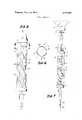
- FIG. 1is a front elevational view of the measuring chamber showing the optical illusion of the lateral offset in the two stripes when viewed straight on from its frontal calibrations;
- FIG. 3is a view of the measuring chamber of this invention when viewed from the right of the calibrations;
- FIG. 4is a sectional view taken along line 44 of FIG. 3 showing the directional view
- FIG. 5is a view of the measuring chamber taken from the left of the calibrations along the direction shown in FIG. 6;
- FIG. 6is a sectional view taken along line 66 of FIG. 5 showing the viewing angle
- FIG. 7is a reduced front elevational view of the empty measuring chamber containing the two opaqure stripes and showing the administration set connecting between a liquid supply bottle and a venous needle.
- the administration set described in this inventionincludes a flexible conduit 1.
- This conduitconnects between a liquid supply bottle and a patient as will be explained in more detail in FIG. 7.
- the flexible conduithas an enlarged measuring chamber 2 connected in series with this flexible conduit.
- This enlarged chamberhas calibrated inidicia 3 shown here to measure between 0 and ml. If desired, the chamber can be made longer and have a capacity of ml.
- This chamber 2includes a cylindrical transparent side wall 4 connected at its upper end to a top cap 5 and at its lower end to a bottom cap 6.
- the top caphas an inlet 7, an additive medication puncture site 8 and a valved vent system 9.
- top cap and valve 9The details of the top cap and valve 9 are explained in more detail in a co-pending application entitled MEDICAL LIQUID ADMINIS- TRATION SET FOR RATE OR VOLUME DELIV- ERY, Ser. No. 202,505, filed Nov. 26, 1971.
- a secondary drip chamber 10Connected to bottom cap 6 is also a secondary drip chamber 10 with a drip former 11. The purpose of this secondary drip chamber is to measure the flow rate of liquid in the administration set simultaneously with the volume measurement taken in the enlarged chamber 2.
- the transparent chamberhas an air-liquid interface 12 which shows the chamber contains 90 ml. of liquid. As liquid is dispensed from this .chamber this interface or liquid surface level will descend. Because the volume delivered is directly measured by interface 12, it is very important to accurately know it s position.
- each stripeoccupies approximately 50 of the circumference of the cylindrical side wall. These stripes could each cover between 30 and 65 of the cylindrical walls surface. Also each stripe is spaced approximately 12 rearwardly of a diametric plane 15 shown in dotted line in FIG. 2, but could be from 5 to 20 back from the diametric plane. There is a transparent segment between the two stripes of from 40 to 70 of the circumference of the chamber. This plane 15 separates the rear half of the chamber from the front half. The front half contains the indicia 3.
- the arrow 16indicates the position of the viewer and the direction of his eyesight.
- the two opaque stripes l3 and 14will appear as shown in FIG.
- FIG. 1the two stripes are readily visible above interface 12. Below interface 12 the liquid which might be distilled water, normal saline, etc., causes an optical defraction of the light rays causing the two stripes to optically disappear below the interface 12. This disappearance is an optical illusion which provides very sharp apparent offsets 17 and 18 at the interface 12. Thus a nurse can readily see how full the chamber 2 is even though she may be several feet from the administration set.
- FIG. 3a very similar administration set is shown having conduit 20 and enlarged chamber 21 with a top cap 22 and a bottom cap 23.
- the chamber portion of this administration setis identical with that shown in FIG. 1 in regard to the indicia 24 and the opaque stripes 25 and 26.
- the sectional view through 44 as shown in FIG. 4illustrates the optical illusion created when the chamber 21 is rotated from that shown in FIG. 2 so the viewer sites along arrow 32.
- the front and rear half of the chamberare still shown separated by a diametric plane 33.
- the two opaque stripes and 26give an optical illusion that the entire chamber beneath an interface 34 is opaque.
- some of the numeralshave been blanked out to better illustrate the opaqueness that appears below interface 34 when viewed from this angle.
- the actual chamber 21will readily show both the indicia 24 and the opaque stripes 25 and 26. This is because the indicia will be on the forward half of the chamber toward the viewer.
- the opaque stripes 25 and 26will form an opaque background on a rear half of the chamber.
- the transparent liquidwill be between the indicia and opaque background.
- FIG. 5a chamber 40 is shown which is similar to the other two previously mentioned transparent chambers. However, here the two opaque stripes 41 and 42 extend only along the calibrated length of the transparent side wall 43. The stripes 41 and 42 and indicia 44 all have the same relationship to each other as the stripes and indicia of the FIG. 1 and FIG. 3 versions.
- the chamberhas been rotated so the viewer sites along arrow 46. The front and rear half of the chamber are separated by diametric plane 47.
- the stripe 42is not directly centered behind the viewing site of arrow 46 and the optical illusion appears as shown in FIG. 5.
- the interface 48is shown as having dropped to approximately 55 ml. because of liquid drainage.
- the opaque stripe 41appears as a straight thin band along the left side of the chamber.
- Opaque stripe 42appears to substantially widen at interface 48 to provide an opaque lateral offset at both sides of stripe 42. Because of the viewing angle the two opaque stripes do not make the entire liquid portion of the chamber contents to appear backed by solid opaque background. At this viewing angle there is a transparent section 49. As in FIG. 3 the numerical scale has been sectioned out for purposes of clarity in the drawings. In' actual use these numbers would be readily apparent to the viewer.
- FIG. 7the chamber shown in FIG. 1 is illustrated in reduced scale and attached to a liquid supply bottle 50 through a spike 51 at its top end and has an adapter 52 and venous needle 53 connected at its lower end.
- FIG. 7the chamber 4 is illustrated containing I no liquid. Since there is no transparent liquid to defract the light and create the optical illusion, the two opaque stripes 13 and 14 appear as thin vertical bands along the left and right side of the chamber.
- each of these three measuring chambers(FIG. 1, FIG. 3 and FIG. 5) have the indicia and two opaque stripes in the same annular position relative to each other.
- the different appearing lateral offsets in the opaque stripesoccur because of the different viewing angles as represented by arrow 16 of FIG. 2, arrow 32 of FIG. 4, and arrow 46 of FIG. 6.
- a medical liquid administration setcomprising an enlarged liquid holding measuring chamber having a tubular transparent wall connected to top and bottom closures; said adminstration set having an inlet opening through the top closures; and an outlet opening through the bottom closure, both of said openings being substantially smaller in cross section than the transparent tubular wall; an inlet conduit and an outlet conduit respectively connected to the inlet and outlet openings of the closures, said inlet and outlet conduits being substantially smaller in cross section than the transparent tubular wall; connector means at an end of the inlet conduit for connecting with a liquid supply source; adapter means at an end of the outlet conduit for dispensing liquid; said chamber including a front half and rear half; a plurality of permanent, opaque stripes extending longitudinally on the rear half of the chamber; said tubular transparent wall having an intermediate longitudinal transparent area separating the opaque stripes; permanent, volumetric measuring indicia on a front half of the tubular transparent wall; the opaque stripes and volumetric measuring indicia having a fixed relationship to each other regardless of rotational movement of a tubular transparent wall relative to
- each opaque stripeshas a width of from 30 to 65 of the tubular chambers circumference.
- each opaque stripeis spaced rearwardly from 5 to back from the diametric plane.
- a medical liquid administration setcomprising an elongated tubular conduit having an upper end portion adapted to connect to a liquid supply source, a lower end portion adapted to connect with a patient; an enlarged volumetrically measuring chamber connected in series with the conduit, said chamber including a top cap, a bottom cap and a cylindrical transparent wall having ends joined to said respective caps; two vertical parallel opaque stripes on said transparent tubular wall, said stripes being spaced apart by a vertical transparent section of the tubular wall covering between 40 and of its circumfemece, each of said stripes occupying between 40 and 60 portions of the circumferential distance of the transparent cylindrcal chamber; both of said stripes being located on a rear half portion of the culindrical chamber defined by a vertical diametric plane; and volumetric indicia located on a front half of the cylindrical chamber, the opaque stripes and vertical longitudinal transparent wall section therebetween combining to form optical illusionary lateral offsets immediately adjacent one or more of the opaque stripes at an interface between air and liquid in said measuring chamber partially filled with said liquid and the front half
Landscapes
- Health & Medical Sciences (AREA)
- Heart & Thoracic Surgery (AREA)
- Life Sciences & Earth Sciences (AREA)
- Fluid Mechanics (AREA)
- Vascular Medicine (AREA)
- Engineering & Computer Science (AREA)
- Anesthesiology (AREA)
- General Physics & Mathematics (AREA)
- Biomedical Technology (AREA)
- Hematology (AREA)
- Physics & Mathematics (AREA)
- Animal Behavior & Ethology (AREA)
- General Health & Medical Sciences (AREA)
- Public Health (AREA)
- Veterinary Medicine (AREA)
- Infusion, Injection, And Reservoir Apparatuses (AREA)
- Medical Preparation Storing Or Oral Administration Devices (AREA)
Abstract
Description
Claims (6)
Applications Claiming Priority (1)
| Application Number | Priority Date | Filing Date | Title |
|---|---|---|---|
| US20224371A | 1971-11-26 | 1971-11-26 |
Publications (1)
| Publication Number | Publication Date |
|---|---|
| US3774603Atrue US3774603A (en) | 1973-11-27 |
Family
ID=22749044
Family Applications (1)
| Application Number | Title | Priority Date | Filing Date |
|---|---|---|---|
| US00202243AExpired - LifetimeUS3774603A (en) | 1971-11-26 | 1971-11-26 | Medical liquid administration set with optical liquid level indicator |
Country Status (1)
| Country | Link |
|---|---|
| US (1) | US3774603A (en) |
Cited By (19)
| Publication number | Priority date | Publication date | Assignee | Title |
|---|---|---|---|---|
| US3881640A (en)* | 1973-12-12 | 1975-05-06 | Terrance O Noble | Apparatus for measuring liquid in the reconstitution of antibiotics |
| US4280637A (en)* | 1978-09-15 | 1981-07-28 | Susann I. C. Runciman | Constant feed device |
| US4292969A (en)* | 1979-12-19 | 1981-10-06 | Raible Donald A | Fluid regulating device with torsional control |
| US4673397A (en)* | 1985-08-02 | 1987-06-16 | Baxter Travenol Laboratories, Inc. | Splash back reduction drip chamber |
| US4687473A (en)* | 1986-02-06 | 1987-08-18 | Burron Medical Inc. | Self-contained secondary solution set |
| US4877212A (en)* | 1985-03-02 | 1989-10-31 | Nippo Kabushiki Kaisha | Document stand |
| US5062828A (en)* | 1989-03-13 | 1991-11-05 | Waltz Roger L | Hypodermic syringe |
| US6315760B1 (en) | 2000-05-09 | 2001-11-13 | Inviro Medical Devices Ltd. | Syringe with a background for writing and reading index markings |
| EP1143227A3 (en)* | 2000-04-08 | 2002-06-05 | Flutec Fluidtechnische Geräte Gmbh | Device for the display and control of fluid states |
| US6634524B1 (en)* | 1999-09-14 | 2003-10-21 | Fischbach Kg Kunststoff-Technik | Two-component cartridge for free-flowing media |
| US6877640B1 (en)* | 2003-03-26 | 2005-04-12 | Kevin Frushone | Device for dispensing liquid or powder to washing machine and the like |
| US20050109794A1 (en)* | 2003-11-21 | 2005-05-26 | Thermos L.L.C | Carafe with contents volume indicator |
| US20060178578A1 (en)* | 2005-02-10 | 2006-08-10 | Dennis Tribble | Vision system to calculate a fluid volume in a container |
| US20070088285A1 (en)* | 2005-09-12 | 2007-04-19 | Inviro Medical Devices, Ltd. | Syringe marking template |
| WO2011151656A1 (en) | 2010-06-04 | 2011-12-08 | Ian Guy | Intravenous infusion device with drip chamber and elastic float |
| US20120268741A1 (en)* | 2009-09-18 | 2012-10-25 | Sanofi-Aventis Deutschland Gmbh | Arrangement for determining a longitudinal position of a stopper |
| US9155839B1 (en)* | 2011-04-13 | 2015-10-13 | Perrigo Diabetes Care, Llc | Syringe assembly including volume indicating indicia |
| US9155840B1 (en)* | 2011-04-13 | 2015-10-13 | Perrigo Diabetes Care, Llc | Syringe assembly including volume indicating indicia |
| US11183284B2 (en) | 2015-06-01 | 2021-11-23 | Digital Hospital, Inc. | Dosage confirmation apparatus |
Citations (6)
| Publication number | Priority date | Publication date | Assignee | Title |
|---|---|---|---|---|
| FR595775A (en)* | 1925-03-25 | 1925-10-09 | Improvements in the manufacture of level tubes with scales or colored refracting ribbons, superimposed or juxtaposed, facilitating reading by refraction of the level, in particular in steam boilers and similar vessels | |
| US2303154A (en)* | 1941-12-16 | 1942-11-24 | Ace Glass Inc | Measuring tube |
| US2356267A (en)* | 1942-06-06 | 1944-08-22 | Rudolph J Pelunis | Activated gauge glass refractor |
| US3216419A (en)* | 1963-10-17 | 1965-11-09 | Abbott Lab | Apparatus for administering a parenteral solution provided with a diaphragm float valve |
| US3217709A (en)* | 1962-12-27 | 1965-11-16 | Abbott Lab | Drip meter with reflector for facilitating the countability of transparent and translucent drops of liquid at low levels of general illumination |
| US3690312A (en)* | 1969-12-16 | 1972-09-12 | Saul Leibinzohn | Venous pressure manometric with level magnifying means |
- 1971
- 1971-11-26USUS00202243Apatent/US3774603A/ennot_activeExpired - Lifetime
Patent Citations (6)
| Publication number | Priority date | Publication date | Assignee | Title |
|---|---|---|---|---|
| FR595775A (en)* | 1925-03-25 | 1925-10-09 | Improvements in the manufacture of level tubes with scales or colored refracting ribbons, superimposed or juxtaposed, facilitating reading by refraction of the level, in particular in steam boilers and similar vessels | |
| US2303154A (en)* | 1941-12-16 | 1942-11-24 | Ace Glass Inc | Measuring tube |
| US2356267A (en)* | 1942-06-06 | 1944-08-22 | Rudolph J Pelunis | Activated gauge glass refractor |
| US3217709A (en)* | 1962-12-27 | 1965-11-16 | Abbott Lab | Drip meter with reflector for facilitating the countability of transparent and translucent drops of liquid at low levels of general illumination |
| US3216419A (en)* | 1963-10-17 | 1965-11-09 | Abbott Lab | Apparatus for administering a parenteral solution provided with a diaphragm float valve |
| US3690312A (en)* | 1969-12-16 | 1972-09-12 | Saul Leibinzohn | Venous pressure manometric with level magnifying means |
Cited By (23)
| Publication number | Priority date | Publication date | Assignee | Title |
|---|---|---|---|---|
| US3881640A (en)* | 1973-12-12 | 1975-05-06 | Terrance O Noble | Apparatus for measuring liquid in the reconstitution of antibiotics |
| US4280637A (en)* | 1978-09-15 | 1981-07-28 | Susann I. C. Runciman | Constant feed device |
| US4292969A (en)* | 1979-12-19 | 1981-10-06 | Raible Donald A | Fluid regulating device with torsional control |
| US4877212A (en)* | 1985-03-02 | 1989-10-31 | Nippo Kabushiki Kaisha | Document stand |
| US4673397A (en)* | 1985-08-02 | 1987-06-16 | Baxter Travenol Laboratories, Inc. | Splash back reduction drip chamber |
| US4687473A (en)* | 1986-02-06 | 1987-08-18 | Burron Medical Inc. | Self-contained secondary solution set |
| US5062828A (en)* | 1989-03-13 | 1991-11-05 | Waltz Roger L | Hypodermic syringe |
| US6634524B1 (en)* | 1999-09-14 | 2003-10-21 | Fischbach Kg Kunststoff-Technik | Two-component cartridge for free-flowing media |
| EP1143227A3 (en)* | 2000-04-08 | 2002-06-05 | Flutec Fluidtechnische Geräte Gmbh | Device for the display and control of fluid states |
| US6315760B1 (en) | 2000-05-09 | 2001-11-13 | Inviro Medical Devices Ltd. | Syringe with a background for writing and reading index markings |
| US6877640B1 (en)* | 2003-03-26 | 2005-04-12 | Kevin Frushone | Device for dispensing liquid or powder to washing machine and the like |
| US20050109794A1 (en)* | 2003-11-21 | 2005-05-26 | Thermos L.L.C | Carafe with contents volume indicator |
| US7163125B2 (en)* | 2003-11-21 | 2007-01-16 | Thermos L.L.C. | Carafe with contents volume indicator |
| US20060178578A1 (en)* | 2005-02-10 | 2006-08-10 | Dennis Tribble | Vision system to calculate a fluid volume in a container |
| US7499581B2 (en)* | 2005-02-10 | 2009-03-03 | Forhealth Technologies, Inc. | Vision system to calculate a fluid volume in a container |
| WO2006086222A3 (en)* | 2005-02-10 | 2009-04-23 | Forhealth Technologies Inc | Vision system to calculate a fluid volume in a container |
| US20070088285A1 (en)* | 2005-09-12 | 2007-04-19 | Inviro Medical Devices, Ltd. | Syringe marking template |
| US20120268741A1 (en)* | 2009-09-18 | 2012-10-25 | Sanofi-Aventis Deutschland Gmbh | Arrangement for determining a longitudinal position of a stopper |
| US8773660B2 (en)* | 2009-09-18 | 2014-07-08 | Sanofi—Aventis Deutschland GmbH | Arrangement for determining a longitudinal position of a stopper |
| WO2011151656A1 (en) | 2010-06-04 | 2011-12-08 | Ian Guy | Intravenous infusion device with drip chamber and elastic float |
| US9155839B1 (en)* | 2011-04-13 | 2015-10-13 | Perrigo Diabetes Care, Llc | Syringe assembly including volume indicating indicia |
| US9155840B1 (en)* | 2011-04-13 | 2015-10-13 | Perrigo Diabetes Care, Llc | Syringe assembly including volume indicating indicia |
| US11183284B2 (en) | 2015-06-01 | 2021-11-23 | Digital Hospital, Inc. | Dosage confirmation apparatus |
Similar Documents
| Publication | Publication Date | Title |
|---|---|---|
| US3774603A (en) | Medical liquid administration set with optical liquid level indicator | |
| US3776229A (en) | Medical liquid administration set for rate or volume delivery | |
| CA2699402C (en) | Medical fluid container | |
| US4191183A (en) | Mixing chamber for use in plural medical liquid intravenous administration set | |
| US5423750A (en) | Transparent color-coding of intravenous tubing and intravenous fluid reservoir | |
| US4909790A (en) | Liquid infusion device | |
| US4391598A (en) | Intravenous drug additive delivery system with electronic control | |
| US3921630A (en) | Thermoplastic bottle with controlled lateral collapse and method of dispensing liquid therefrom | |
| US3216418A (en) | Apparatus for administering parenteral solutions | |
| US5885250A (en) | Fluid delivery device with conformable ullage | |
| US3965897A (en) | Measured volume drug administration device for use with intravenous feeding pump | |
| US4223695A (en) | Novel valve employing hydrophobic and hydrophilic membranes | |
| US4433974A (en) | Mixing system for parenteral liquids | |
| CA1127042A (en) | Valve employing hydrophobic and hydrophilic membranes | |
| US4576594A (en) | Vented drip chamber for use with a syringe | |
| ATE43503T1 (en) | INFUSION SYSTEM WITH VACUUM BOTTLE. | |
| SE468464B (en) | DEVICE FOR CONNECTING A SPIRIT OF A CATHETER FOR LIQUID MEDICINES TO A DEVICE FOR CONNECTING A SUBJECT SPRAY TO A Vial FOR THE MEDICINAL PRODUCT | |
| US2969063A (en) | Parenteral fluid administration equipment | |
| ES2553127T3 (en) | Bypass duct connector for composition system | |
| US3233457A (en) | Regulatable flow meter unit for intravenous fluids | |
| US3690312A (en) | Venous pressure manometric with level magnifying means | |
| US3951145A (en) | Intravenous measuring chamber | |
| US4250879A (en) | Equipment sets and system for the sequential administration of medical liquids at dual flow rates employing a combined air barrier and liquid sequencing valve | |
| US4372306A (en) | Equipment sets having a combined air barrier and liquid sequencing device for the sequential administration of medical liquids at dual flow rates | |
| CA1323003C (en) | Fluid dispensing apparatus |
Legal Events
| Date | Code | Title | Description |
|---|---|---|---|
| STCF | Information on status: patent grant | Free format text:PATENTED FILE - (OLD CASE ADDED FOR FILE TRACKING PURPOSES) | |
| AS | Assignment | Owner name:KENDALL MCGAW LABORATORIES, INC., A CORP OF OH,CAL Free format text:ASSIGNMENT OF ASSIGNORS INTEREST;ASSIGNOR:AMERICAN HOSPITAL SUPPLY CORPORATION, A CORP OF IL;REEL/FRAME:004600/0460 Effective date:19851126 Owner name:KENDALL MCGAW LABORATORIES, INC., 2525 MCGAW AVENU Free format text:ASSIGNMENT OF ASSIGNORS INTEREST. EFFECTIVE NOVEMBER 26, 1985.;ASSIGNOR:AMERICAN HOSPITAL SUPPLY CORPORATION, A CORP OF IL;REEL/FRAME:004600/0460 Effective date:19851126 | |
| AS | Assignment | Owner name:WELLS FARGO BANK, N.A. Free format text:SECURITY INTEREST;ASSIGNOR:MCGAW, INC., A CORP. OF OH;REEL/FRAME:005477/0809 Effective date:19901022 | |
| AS | Assignment | Owner name:KENDALL MCGAW LABORATORIES, INC. AN OH CORPORAT Free format text:RELEASED BY SECURED PARTY;ASSIGNOR:MANUFACTURERS HANOVER TRUST COMPANY;REEL/FRAME:005709/0001 Effective date:19901015 | |
| AS | Assignment | Owner name:KENDALL MCGAW LABORATORIES, INC., AN OH CORP. Free format text:RELEASED BY SECURED PARTY;ASSIGNOR:MANUFACTURERS HANOVER TRUST COMPANY;REEL/FRAME:005515/0206 Effective date:19901015 | |
| AS | Assignment | Owner name:MCGAW, INC. A CORP. OF DELAWARE Free format text:SECURITY INTEREST;ASSIGNOR:WELLS FARGO BANK, N.A.;REEL/FRAME:006139/0057 Effective date:19920401 |