US3765494A - Circulating sleeve - Google Patents
Circulating sleeveDownload PDFInfo
- Publication number
- US3765494A US3765494AUS00246293AUS3765494DAUS3765494AUS 3765494 AUS3765494 AUS 3765494AUS 00246293 AUS00246293 AUS 00246293AUS 3765494D AUS3765494D AUS 3765494DAUS 3765494 AUS3765494 AUS 3765494A
- Authority
- US
- United States
- Prior art keywords
- sleeve
- bore
- conduit
- pipe
- shoulder
- Prior art date
- Legal status (The legal status is an assumption and is not a legal conclusion. Google has not performed a legal analysis and makes no representation as to the accuracy of the status listed.)
- Expired - Lifetime
Links
- 238000005553drillingMethods0.000claimsabstractdescription32
- 239000012530fluidSubstances0.000claimsabstractdescription11
- 230000013011matingEffects0.000claimsdescription4
- 238000000034methodMethods0.000description8
- 230000015572biosynthetic processEffects0.000description3
- 239000004020conductorSubstances0.000description3
- 238000005755formation reactionMethods0.000description3
- 238000012986modificationMethods0.000description2
- 230000004048modificationEffects0.000description2
- 230000002093peripheral effectEffects0.000description2
- 239000003208petroleumSubstances0.000description2
- 230000002596correlated effectEffects0.000description1
- 238000012423maintenanceMethods0.000description1
- 238000004519manufacturing processMethods0.000description1
- 239000003129oil wellSubstances0.000description1
Images

Classifications
- E—FIXED CONSTRUCTIONS
- E21—EARTH OR ROCK DRILLING; MINING
- E21B—EARTH OR ROCK DRILLING; OBTAINING OIL, GAS, WATER, SOLUBLE OR MELTABLE MATERIALS OR A SLURRY OF MINERALS FROM WELLS
- E21B17/00—Drilling rods or pipes; Flexible drill strings; Kellies; Drill collars; Sucker rods; Cables; Casings; Tubings
- E—FIXED CONSTRUCTIONS
- E21—EARTH OR ROCK DRILLING; MINING
- E21B—EARTH OR ROCK DRILLING; OBTAINING OIL, GAS, WATER, SOLUBLE OR MELTABLE MATERIALS OR A SLURRY OF MINERALS FROM WELLS
- E21B23/00—Apparatus for displacing, setting, locking, releasing or removing tools, packers or the like in boreholes or wells
- E21B23/02—Apparatus for displacing, setting, locking, releasing or removing tools, packers or the like in boreholes or wells for locking the tools or the like in landing nipples or in recesses between adjacent sections of tubing
- E—FIXED CONSTRUCTIONS
- E21—EARTH OR ROCK DRILLING; MINING
- E21B—EARTH OR ROCK DRILLING; OBTAINING OIL, GAS, WATER, SOLUBLE OR MELTABLE MATERIALS OR A SLURRY OF MINERALS FROM WELLS
- E21B47/00—Survey of boreholes or wells
- E21B47/01—Devices for supporting measuring instruments on drill bits, pipes, rods or wirelines; Protecting measuring instruments in boreholes against heat, shock, pressure or the like
Definitions
- ABSTRACTIn a drilling system, a subassembly provides a means for seating an instrument housing in the drill strin during a drilling operation and for permittin flowof drilling fluids around the instrume [52] US Cl 175/320, 175/45 [51] Int. E2lb l7/00 g a normal nt housing.
- the seatalso provides means for orienting the instr ment housing in a predetermined position relative to a [56] References cued portion of the drill system.
- the present inventionpertains to a circulating sleeve and more particularly to an apparatus for orienting an instrument within a drill string and providing for the circulation of fluid about the instrument tov permit drilling when an instrument is seated therein.
- directional drillingis applied to such operations.
- One example of the use of such directional drilling operationsis found in the drilling of oil wells from offshore platforms. It is a common practice to build large drilling platforms which are permanently secured to the ocean floor and from which a multiplicity of wells are drilled. Because of the number of wells which are drilled from a single platform, it is necessary to drill the holes laterally away from the platform so that earth formations containing petroleum reservoirs may be penetrated at distances laterally spaced from the platform. This procedure permits production from as great an area as possible from a single platform. It is easily understood how important the maintenance of direction and dip of such boreholes is in order to penetrate particular formations at predetermined depths and thereby intersect the desired petroleum reservoirs.
- One technique for obtaining such information as to the direction of a boreholeis to cease drilling and run a surveying instrument into the drill pipe on a wire line.
- the instrumentmay be go-deviled to the bottom of the drill pipe.
- the instrumentis oriented with respect to the drill stem by means of a muleshoe sub located at the lower end of the drill stem.
- the muleshoeis simply a device for capturing the tool and orienting the tool in a predetermined radial direction with respect to a position on the drill ste'm.
- the drill stem normally used in such'a directional drilling operationincludes what is normally termed a bent sub," at its lower end which places a bend in the lower end of the stem and thereby permits angular deviation of the drill bit.
- the muleshoeis normally oriented with respect to the bent sub. This in turn orients the instrument which is being positioned in the lower end of the drill stem. This series of orientation procedures provides a correlation between the direction in which the drill bit is angled and the directional alignment of the survey instrument.
- the survey instrumentis operated to generate a record, generally be means of a timing mechanism, the tool is retrieved to the surface by means of a wire line. The record is then processed and examined to determine the direction in which the hole is being drilled.
- the present inventioncontemplates a drill pipe having a recessed portion therein forming a seat within the bore of the pipe.
- a sleeve which is sized for reception within the recessed portionhas a shoulder which when received within the recess mates with the seat.
- a plurality of Iongitudinal ribsare formed on the sleeve and extend upwardly from the shoulder. Means extend inwardly from the sleeve for engaging a mating surface on an instrument housing to thereby locate the instrument in a predetermined manner within the sleeve.
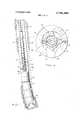
- FIG. 1 of the drawingsthe lower end of the'drill stem is shown including a drill collar 27 and a muleshoe orienting sub 28.
- a bent sub 29, mud motor'or turbine 31, and a rotating bit sub 32are positioned below the orienting sub.
- An instrument which for the purpose of this disclosure shall be referred to as an orienting tool 33is shown positioned within the interior bore of the drill collar and is connected at its upper end with a conductor cable 26 extending to the surface.
- the conductor cablewould extend through a line wiper at the surface and be taken up on a motor driven drum which permits its playout and take up during operations.
- the line wiperis constructed to seal off well pressure at the wellhead during line operations in the drill pipe.
- muleshoe sleeve 34is shown positioned within the muleshoe orienting sub 28 and is oriented therein in a predetermined fashion.
- the sleeve 34is held in the predetermined position within the sub by means of a screw or the like 36 extending through the side wall of the sub 28.
- the muleshoe sleeve 34is shown having a key 37 positionedin its sidewall and extending inwardly into the sleeve bore.
- the muleshoe and its keyare normally oriented directionally with respect to the bent sub and thus with respect to the drill bit which derives its direction of inclination by means of the bent sub.
- This predetermined alignment of the muleshoe key with respect to the bent subis convenient for purposes of determining the original orientation of the drill with respect to surface indications of tool direction and thereafter for making compensating changes in drilling direction.
- the muleshoe sleeve or circulating sleeve as it will be hereinafter referred to,may be utilized to positionally locate various types of instruments within a drill 'pipe; however, since one of its primary uses is for locating directional drilling orienting instruments this disclosure will continue to use such an instrument as an example.
- the orienting tool 33which is shown schematically in FIG. 1 includes a muleshoe 39 which is secured to the lower end of the tool string.
- the muleshoeincludes a protruding shaft or stinger 41 having a tapered end 42 (see FIG. 2) for guiding the stinger into the muleshoe sleeve 34.
- a shoulder 43extends spirally around'opposite sides of the stinger, meeting at a pointed terminus 44, to form a camming surface. On the opposite side of the tool from the terminus 44, the spiral shoulders 43 meet to form a short longitudinally extending slot 45.
- the slot 45is sized to receive the inwardly extending key 37 on the muleshoe sleeve 34 when the tool 33 is positioned in the drill pipe.
- the tool string 33further includes a muleshoe adjuster which permits rotation of the muleshoe 39 relative to the tool string 33.
- the adjusterincludes includes mating portions (not shown) between the muleshoe and tool string to permit relative rotation therebetween, and a locking collar 35 for securing the tool string and muleshoe in a fixed rotational position. Greater detail of the muleshoe and its functional use with an orienting tool is shown in co-pending U.S. Pat. application Ser. No. 86,877, now U.S. Pat. No. 3,7l8,l94, which is assigned to same assignor as the present application.
- Sub 28has a recessed bore portion 46 with a tapered seat 47 at its lower end.
- the circulating sleeve 34is shown positioned within the sub 28.
- the sleeve 34has a body portion 49 with longitudinal ribs 48 extending outwardly therefrom into contact with the recessed inner bore portion 46 of the sub 28.
- the longitudinal ribs 48extend downwardly below the lower end of the body portion 49.
- a cylindrical sleeve 51is formed at the bottom end of the longitudinal ribs. Tapered top and bottom surfaces 52 and 53, respectively, are formed on the sleeve 51.
- the lower surface 53is arranged to matingly seat on the tapered surface 47 of the recessed bore 46 in sub 28.
- Upper and lower peripheral grooves 54 and 56are formed on the surface of the exterior wall of sleeve 51, and are sized to receive O-ring seals therein.
- Another peripheral groove 57is formed between the grooves 54 and 56 in the outer wall of the sleeve 51 for receiving an inwardly extending end portion of a set screw 36.
- the body portion 49 of the circulating sleeve 34 and one of the longitudinal ribs 48have an'aligned opening formed through the rib and body portion for receiving the key 37.
- the key 37has an enlarged shoulder portion 61 formed thereon which abuts a complimentary shoulder formed in the rib opening.
- the circulating sleeve 34is inserted into the upper end of sub 28 until the lower tapered surface 53 on sleeve 51 is matingly seated on tapered surface 47 within the bore of sub 28.
- the circulating sleeveis then rotated within the bore of sub 28 until the key 37 which extends inwardly from the sleeve is positioned in accordance with a predetermined arrangement to permit orientation with respect to a portion of the drill stem.
- the predetermined alignment of the key 37is in some relationship with the bent sub 29 so that it is known that the muleshoe key 37 is pointing in a particular direction with respect to that in which the drill is pointing.
- This arrangementprovides means for determining, by means of an orienting instrument to be located within the muleshoe sub in what direction the drilling operation is being conducted.
- set screws 36are rotated until they extend inwardly into the groove 57 on lower sleeve 51 and tightened therein to hole the sleeve in a fixed relationship with the sub 28 and thereby prevent its rotation within the sub.
- the sub 28is made up in the drill string and the drill string is lowered into the wellbore for purposes of performing the drilling operation.
- the volume of fluid that may be circulated through the systemis sufficient to drive the mud motor or turbine during drilling operations while permitting the continuous use of an orienting instrument.
- a drilling systemutilizing a hollow conduit for carrying a drilling fluid means for seating an instrument housing within the conduit while performing a drilling operation
- which meansincludes: a seat formed within the bore of said conduit, a sleeve sized for reception within the bore of said conduit, shoulder means on one end of-said sleeve for providing a mating reception of said sleeve within said seat, said shoulder means being sized for close fitting reception within said conduit, a plurality of longitudinal ribs on said sleeve extending above said shoulder means and key means extending inwardly from said sleeve for orienting an instrument housing.
- a circulating sleeve for seating and orienting an instrument housing within the bore of a drill pipe during a drilling operation and arranged to permit the flow of fluids through the drill pipe when an instrument housing is positioned thereincomprising: a sleeve for reception within the bore of the pipe, and having a cylindrical portion with longitudinal ribs formed thereon for engaging the bore of the pipe and maintain said cylindrical portion in a spaced position from said bore; a shoulder formed on said sleeve for engaging a seat in the pipe; key means extending from the wall of said cylindrical portion into its bore for engaging a portion of the instrument housing to orient the housing with respect to said sleeve; and means on said sleeve for receiving a member extending from the wall of the pipe for holding said sleeve against rotation relative to the pipe.
Landscapes
- Engineering & Computer Science (AREA)
- Life Sciences & Earth Sciences (AREA)
- Geology (AREA)
- Mining & Mineral Resources (AREA)
- Physics & Mathematics (AREA)
- Environmental & Geological Engineering (AREA)
- Fluid Mechanics (AREA)
- General Life Sciences & Earth Sciences (AREA)
- Geochemistry & Mineralogy (AREA)
- Mechanical Engineering (AREA)
- Geophysics (AREA)
- Earth Drilling (AREA)
Abstract
Description
Claims (5)
Applications Claiming Priority (1)
| Application Number | Priority Date | Filing Date | Title |
|---|---|---|---|
| US24629372A | 1972-04-21 | 1972-04-21 |
Publications (1)
| Publication Number | Publication Date |
|---|---|
| US3765494Atrue US3765494A (en) | 1973-10-16 |
Family
ID=22930055
Family Applications (1)
| Application Number | Title | Priority Date | Filing Date |
|---|---|---|---|
| US00246293AExpired - LifetimeUS3765494A (en) | 1972-04-21 | 1972-04-21 | Circulating sleeve |
Country Status (1)
| Country | Link |
|---|---|
| US (1) | US3765494A (en) |
Cited By (38)
| Publication number | Priority date | Publication date | Assignee | Title |
|---|---|---|---|---|
| US4130162A (en)* | 1977-07-01 | 1978-12-19 | Wilson Industries, Inc. | Flow-through mule shoe sub |
| US4181014A (en)* | 1978-05-04 | 1980-01-01 | Scientific Drilling Controls, Inc. | Remote well signalling apparatus and methods |
| US4550392A (en)* | 1982-03-08 | 1985-10-29 | Exploration Logging, Inc. | Apparatus for well logging telemetry |
| US4789032A (en)* | 1987-09-25 | 1988-12-06 | Rehm William A | Orienting and circulating sub |
| GB2232177A (en)* | 1989-05-25 | 1990-12-05 | Coal Ind | Mule shoe assembly |
| WO1998054438A1 (en)* | 1997-05-27 | 1998-12-03 | Pegasus Drilling Technologies, L.L.C. | Bottomhole assembly orienting sub |
| US20060266555A1 (en)* | 1998-12-21 | 2006-11-30 | Chen Chen-Kang D | Steerable drilling system and method |
| US20070227780A1 (en)* | 2006-03-31 | 2007-10-04 | Macpherson Calum Robert | Drill string system for performing measurement while drilling and logging while drilling operations |
| US7658196B2 (en) | 2005-02-24 | 2010-02-09 | Ethicon Endo-Surgery, Inc. | System and method for determining implanted device orientation |
| US7775966B2 (en) | 2005-02-24 | 2010-08-17 | Ethicon Endo-Surgery, Inc. | Non-invasive pressure measurement in a fluid adjustable restrictive device |
| US7775215B2 (en) | 2005-02-24 | 2010-08-17 | Ethicon Endo-Surgery, Inc. | System and method for determining implanted device positioning and obtaining pressure data |
| US7844342B2 (en) | 2008-02-07 | 2010-11-30 | Ethicon Endo-Surgery, Inc. | Powering implantable restriction systems using light |
| US7927270B2 (en) | 2005-02-24 | 2011-04-19 | Ethicon Endo-Surgery, Inc. | External mechanical pressure sensor for gastric band pressure measurements |
| US8016745B2 (en) | 2005-02-24 | 2011-09-13 | Ethicon Endo-Surgery, Inc. | Monitoring of a food intake restriction device |
| US8016744B2 (en) | 2005-02-24 | 2011-09-13 | Ethicon Endo-Surgery, Inc. | External pressure-based gastric band adjustment system and method |
| US8034065B2 (en) | 2008-02-26 | 2011-10-11 | Ethicon Endo-Surgery, Inc. | Controlling pressure in adjustable restriction devices |
| US8057492B2 (en) | 2008-02-12 | 2011-11-15 | Ethicon Endo-Surgery, Inc. | Automatically adjusting band system with MEMS pump |
| US8066629B2 (en) | 2005-02-24 | 2011-11-29 | Ethicon Endo-Surgery, Inc. | Apparatus for adjustment and sensing of gastric band pressure |
| US8100870B2 (en) | 2007-12-14 | 2012-01-24 | Ethicon Endo-Surgery, Inc. | Adjustable height gastric restriction devices and methods |
| US8114345B2 (en) | 2008-02-08 | 2012-02-14 | Ethicon Endo-Surgery, Inc. | System and method of sterilizing an implantable medical device |
| US8142452B2 (en) | 2007-12-27 | 2012-03-27 | Ethicon Endo-Surgery, Inc. | Controlling pressure in adjustable restriction devices |
| US8152710B2 (en) | 2006-04-06 | 2012-04-10 | Ethicon Endo-Surgery, Inc. | Physiological parameter analysis for an implantable restriction device and a data logger |
| US8187163B2 (en) | 2007-12-10 | 2012-05-29 | Ethicon Endo-Surgery, Inc. | Methods for implanting a gastric restriction device |
| US8187162B2 (en) | 2008-03-06 | 2012-05-29 | Ethicon Endo-Surgery, Inc. | Reorientation port |
| US8192350B2 (en) | 2008-01-28 | 2012-06-05 | Ethicon Endo-Surgery, Inc. | Methods and devices for measuring impedance in a gastric restriction system |
| US8221439B2 (en) | 2008-02-07 | 2012-07-17 | Ethicon Endo-Surgery, Inc. | Powering implantable restriction systems using kinetic motion |
| US8233995B2 (en) | 2008-03-06 | 2012-07-31 | Ethicon Endo-Surgery, Inc. | System and method of aligning an implantable antenna |
| US8337389B2 (en) | 2008-01-28 | 2012-12-25 | Ethicon Endo-Surgery, Inc. | Methods and devices for diagnosing performance of a gastric restriction system |
| US8377079B2 (en) | 2007-12-27 | 2013-02-19 | Ethicon Endo-Surgery, Inc. | Constant force mechanisms for regulating restriction devices |
| US8591395B2 (en) | 2008-01-28 | 2013-11-26 | Ethicon Endo-Surgery, Inc. | Gastric restriction device data handling devices and methods |
| US8591532B2 (en) | 2008-02-12 | 2013-11-26 | Ethicon Endo-Sugery, Inc. | Automatically adjusting band system |
| US8870742B2 (en) | 2006-04-06 | 2014-10-28 | Ethicon Endo-Surgery, Inc. | GUI for an implantable restriction device and a data logger |
| US20160245068A1 (en)* | 2015-02-20 | 2016-08-25 | Aps Technology, Inc. | Pressure locking device for downhole tools |
| US9765613B2 (en) | 2014-03-03 | 2017-09-19 | Aps Technology, Inc. | Drilling system and electromagnetic telemetry tool with an electrical connector assembly and associated methods |
| US9790784B2 (en) | 2014-05-20 | 2017-10-17 | Aps Technology, Inc. | Telemetry system, current sensor, and related methods for a drilling system |
| EP3140496A4 (en)* | 2014-05-06 | 2017-12-13 | Sharewell Energy Services, LLC | Orienting hanger assembly for deploying mwd tools |
| US20180363377A1 (en)* | 2017-06-20 | 2018-12-20 | Subhra Kanchan Dey | Downhole tool assemblies with selectively orientable and lockable members |
| US10190408B2 (en) | 2013-11-22 | 2019-01-29 | Aps Technology, Inc. | System, apparatus, and method for drilling |
Citations (5)
| Publication number | Priority date | Publication date | Assignee | Title |
|---|---|---|---|---|
| US2197227A (en)* | 1938-10-17 | 1940-04-16 | Thomas C Strength | Directional well drilling tool |
| US3052309A (en)* | 1958-10-30 | 1962-09-04 | Eastman Oil Well Survey Co | Apparatus for orienting well drilling equipment |
| US3361204A (en)* | 1965-06-25 | 1968-01-02 | Pan American Petroleum Corp | Method and apparatus for treating an underground formation |
| US3414071A (en)* | 1966-09-26 | 1968-12-03 | Halliburton Co | Oriented perforate test and cement squeeze apparatus |
| US3450216A (en)* | 1965-05-21 | 1969-06-17 | Christensen Diamond Prod Co | Core orienting apparatus and method |
- 1972
- 1972-04-21USUS00246293Apatent/US3765494A/ennot_activeExpired - Lifetime
Patent Citations (5)
| Publication number | Priority date | Publication date | Assignee | Title |
|---|---|---|---|---|
| US2197227A (en)* | 1938-10-17 | 1940-04-16 | Thomas C Strength | Directional well drilling tool |
| US3052309A (en)* | 1958-10-30 | 1962-09-04 | Eastman Oil Well Survey Co | Apparatus for orienting well drilling equipment |
| US3450216A (en)* | 1965-05-21 | 1969-06-17 | Christensen Diamond Prod Co | Core orienting apparatus and method |
| US3361204A (en)* | 1965-06-25 | 1968-01-02 | Pan American Petroleum Corp | Method and apparatus for treating an underground formation |
| US3414071A (en)* | 1966-09-26 | 1968-12-03 | Halliburton Co | Oriented perforate test and cement squeeze apparatus |
Cited By (41)
| Publication number | Priority date | Publication date | Assignee | Title |
|---|---|---|---|---|
| US4130162A (en)* | 1977-07-01 | 1978-12-19 | Wilson Industries, Inc. | Flow-through mule shoe sub |
| US4181014A (en)* | 1978-05-04 | 1980-01-01 | Scientific Drilling Controls, Inc. | Remote well signalling apparatus and methods |
| US4550392A (en)* | 1982-03-08 | 1985-10-29 | Exploration Logging, Inc. | Apparatus for well logging telemetry |
| US4789032A (en)* | 1987-09-25 | 1988-12-06 | Rehm William A | Orienting and circulating sub |
| GB2232177A (en)* | 1989-05-25 | 1990-12-05 | Coal Ind | Mule shoe assembly |
| WO1998054438A1 (en)* | 1997-05-27 | 1998-12-03 | Pegasus Drilling Technologies, L.L.C. | Bottomhole assembly orienting sub |
| US5881824A (en)* | 1997-05-27 | 1999-03-16 | Pegasus Drilling Technologies L.L.C. | Bottomhole assembly orienting sub |
| US7621343B2 (en) | 1998-12-21 | 2009-11-24 | Halliburton Energy Services, Inc. | Steerable drilling system and method |
| US20060266555A1 (en)* | 1998-12-21 | 2006-11-30 | Chen Chen-Kang D | Steerable drilling system and method |
| US7658196B2 (en) | 2005-02-24 | 2010-02-09 | Ethicon Endo-Surgery, Inc. | System and method for determining implanted device orientation |
| US7775966B2 (en) | 2005-02-24 | 2010-08-17 | Ethicon Endo-Surgery, Inc. | Non-invasive pressure measurement in a fluid adjustable restrictive device |
| US7775215B2 (en) | 2005-02-24 | 2010-08-17 | Ethicon Endo-Surgery, Inc. | System and method for determining implanted device positioning and obtaining pressure data |
| US7927270B2 (en) | 2005-02-24 | 2011-04-19 | Ethicon Endo-Surgery, Inc. | External mechanical pressure sensor for gastric band pressure measurements |
| US8016745B2 (en) | 2005-02-24 | 2011-09-13 | Ethicon Endo-Surgery, Inc. | Monitoring of a food intake restriction device |
| US8016744B2 (en) | 2005-02-24 | 2011-09-13 | Ethicon Endo-Surgery, Inc. | External pressure-based gastric band adjustment system and method |
| US8066629B2 (en) | 2005-02-24 | 2011-11-29 | Ethicon Endo-Surgery, Inc. | Apparatus for adjustment and sensing of gastric band pressure |
| US20070227780A1 (en)* | 2006-03-31 | 2007-10-04 | Macpherson Calum Robert | Drill string system for performing measurement while drilling and logging while drilling operations |
| US8870742B2 (en) | 2006-04-06 | 2014-10-28 | Ethicon Endo-Surgery, Inc. | GUI for an implantable restriction device and a data logger |
| US8152710B2 (en) | 2006-04-06 | 2012-04-10 | Ethicon Endo-Surgery, Inc. | Physiological parameter analysis for an implantable restriction device and a data logger |
| US8187163B2 (en) | 2007-12-10 | 2012-05-29 | Ethicon Endo-Surgery, Inc. | Methods for implanting a gastric restriction device |
| US8100870B2 (en) | 2007-12-14 | 2012-01-24 | Ethicon Endo-Surgery, Inc. | Adjustable height gastric restriction devices and methods |
| US8377079B2 (en) | 2007-12-27 | 2013-02-19 | Ethicon Endo-Surgery, Inc. | Constant force mechanisms for regulating restriction devices |
| US8142452B2 (en) | 2007-12-27 | 2012-03-27 | Ethicon Endo-Surgery, Inc. | Controlling pressure in adjustable restriction devices |
| US8591395B2 (en) | 2008-01-28 | 2013-11-26 | Ethicon Endo-Surgery, Inc. | Gastric restriction device data handling devices and methods |
| US8192350B2 (en) | 2008-01-28 | 2012-06-05 | Ethicon Endo-Surgery, Inc. | Methods and devices for measuring impedance in a gastric restriction system |
| US8337389B2 (en) | 2008-01-28 | 2012-12-25 | Ethicon Endo-Surgery, Inc. | Methods and devices for diagnosing performance of a gastric restriction system |
| US7844342B2 (en) | 2008-02-07 | 2010-11-30 | Ethicon Endo-Surgery, Inc. | Powering implantable restriction systems using light |
| US8221439B2 (en) | 2008-02-07 | 2012-07-17 | Ethicon Endo-Surgery, Inc. | Powering implantable restriction systems using kinetic motion |
| US8114345B2 (en) | 2008-02-08 | 2012-02-14 | Ethicon Endo-Surgery, Inc. | System and method of sterilizing an implantable medical device |
| US8591532B2 (en) | 2008-02-12 | 2013-11-26 | Ethicon Endo-Sugery, Inc. | Automatically adjusting band system |
| US8057492B2 (en) | 2008-02-12 | 2011-11-15 | Ethicon Endo-Surgery, Inc. | Automatically adjusting band system with MEMS pump |
| US8034065B2 (en) | 2008-02-26 | 2011-10-11 | Ethicon Endo-Surgery, Inc. | Controlling pressure in adjustable restriction devices |
| US8233995B2 (en) | 2008-03-06 | 2012-07-31 | Ethicon Endo-Surgery, Inc. | System and method of aligning an implantable antenna |
| US8187162B2 (en) | 2008-03-06 | 2012-05-29 | Ethicon Endo-Surgery, Inc. | Reorientation port |
| US10190408B2 (en) | 2013-11-22 | 2019-01-29 | Aps Technology, Inc. | System, apparatus, and method for drilling |
| US9765613B2 (en) | 2014-03-03 | 2017-09-19 | Aps Technology, Inc. | Drilling system and electromagnetic telemetry tool with an electrical connector assembly and associated methods |
| EP3140496A4 (en)* | 2014-05-06 | 2017-12-13 | Sharewell Energy Services, LLC | Orienting hanger assembly for deploying mwd tools |
| US9790784B2 (en) | 2014-05-20 | 2017-10-17 | Aps Technology, Inc. | Telemetry system, current sensor, and related methods for a drilling system |
| US20160245068A1 (en)* | 2015-02-20 | 2016-08-25 | Aps Technology, Inc. | Pressure locking device for downhole tools |
| US9976413B2 (en)* | 2015-02-20 | 2018-05-22 | Aps Technology, Inc. | Pressure locking device for downhole tools |
| US20180363377A1 (en)* | 2017-06-20 | 2018-12-20 | Subhra Kanchan Dey | Downhole tool assemblies with selectively orientable and lockable members |
Similar Documents
| Publication | Publication Date | Title |
|---|---|---|
| US3765494A (en) | Circulating sleeve | |
| AU736692B2 (en) | Method and apparatus for locating indexing systems in a cased well and conducting multilateral branch operations | |
| EP0840834B1 (en) | Apparatus and process for drilling and completing multiple wells | |
| EP1440220B1 (en) | An entry well with slanted well bores and method | |
| US6412574B1 (en) | Method of forming a subsea borehole from a drilling vessel in a body of water of known depth | |
| US4852666A (en) | Apparatus for and a method of drilling offset wells for producing hydrocarbons | |
| EP0452126B1 (en) | Apparatus for orienting perforating gun | |
| US5330007A (en) | Template and process for drilling and completing multiple wells | |
| US20120043134A1 (en) | Method and apparatus for cementing drill strings in place for one pass drilling and completion of oil and gas wells | |
| NO316291B1 (en) | Method for drilling underground wells | |
| US6138756A (en) | Milling guide having orientation and depth determination capabilities | |
| US9976413B2 (en) | Pressure locking device for downhole tools | |
| US4379493A (en) | Method and apparatus for preventing wireline kinking in a directional drilling system | |
| US7228901B2 (en) | Method and apparatus for cementing drill strings in place for one pass drilling and completion of oil and gas wells | |
| Gearhart et al. | Mud pulse MWD systems report | |
| US3789936A (en) | Method and apparatus for simultaneously drilling and logging | |
| US7055623B2 (en) | Method for the drilling of the initial phase of deep water oil wells with an underwater well head | |
| US10830040B2 (en) | Field-level analysis of downhole operation logs | |
| US3804168A (en) | Wire line clamp | |
| US10941622B2 (en) | System and methodology utilizing conductor sharing offset shoe | |
| US20190112920A1 (en) | Reciprocating Rotary Valve Actuator System | |
| GB2170842A (en) | Drilling at least one deviated well | |
| US3741013A (en) | Signal responsive display apparatus | |
| US20250020059A1 (en) | Fluid multisample capturing with translating member | |
| Brooks et al. | Development & Application of a Through Tubing Multi-Lateral Re-Entry System. |
Legal Events
| Date | Code | Title | Description |
|---|---|---|---|
| AS | Assignment | Owner name:SPERRY-SUN, INC. Free format text:CERTIFICATE OF INCORPORATION TO RESTATE INCORPORATION, EFFECTIVE JULY 21, 1976;ASSIGNOR:SPERRY-SUN WELL SURVEYING COMPANY;REEL/FRAME:005024/0918 Effective date:19760617 Owner name:BAROID TECHNOLOGY, INC., 3000 NORTH SAM HOUSTON PA Free format text:ASSIGNMENT OF ASSIGNORS INTEREST.;ASSIGNOR:SPERRY-SUN DRILLING SERVICES, INC.;REEL/FRAME:005024/0898 Effective date:19890210 Owner name:SPERRY-SUN DRILLING SERVICES, INC. Free format text:CHANGE OF NAME;ASSIGNOR:NL SPERRY - SUN, INC.;REEL/FRAME:005024/0939 Effective date:19880214 | |
| AS | Assignment | Owner name:CHASE MANHATTAN BANK (NATIONAL ASSOCIATION), THE Free format text:SECURITY INTEREST;ASSIGNOR:BAROID CORPORATION, A CORP. OF DE.;REEL/FRAME:005196/0501 Effective date:19881222 | |
| AS | Assignment | Owner name:SPERRY-SUN, INC., A CORP. OF DE., DELAWARE Free format text:CHANGE OF NAME;ASSIGNOR:SPERRY-SUN WELL SURVEYING COMPANY;REEL/FRAME:005208/0153 Effective date:19760617 Owner name:SPERRY-SUN DRILLING SERVICES, INC. Free format text:CHANGE OF NAME;ASSIGNORS:NL ACQUISTION CORPORATION, (CHANGED TO);SPERRY-SUN, INC., (CHANGED TO );NLSPERRY-SUN, INC., (CHANGED TO);REEL/FRAME:005208/0157 Effective date:19810421 Owner name:BAROID TECHNOLOGY, INC., A CORP. OF DE., DELAWARE Free format text:ASSIGNMENT OF ASSIGNORS INTEREST.;ASSIGNOR:SPERRY-SUN DRILLING SERVICES, INC., A CORP. OF DE.;REEL/FRAME:005208/0161 Effective date:19890613 | |
| AS | Assignment | Owner name:BAROID CORPORATION, TEXAS Free format text:RELEASED BY SECURED PARTY;ASSIGNOR:CHASE MANHATTAN BANK, THE;REEL/FRAME:006085/0590 Effective date:19911021 |