US3749491A - Microfiche duplicator - Google Patents
Microfiche duplicatorDownload PDFInfo
- Publication number
- US3749491A US3749491AUS00224100AUS3749491DAUS3749491AUS 3749491 AUS3749491 AUS 3749491AUS 00224100 AUS00224100 AUS 00224100AUS 3749491D AUS3749491D AUS 3749491DAUS 3749491 AUS3749491 AUS 3749491A
- Authority
- US
- United States
- Prior art keywords
- belt
- film
- roller
- exposure
- copy
- Prior art date
- Legal status (The legal status is an assumption and is not a legal conclusion. Google has not performed a legal analysis and makes no representation as to the accuracy of the status listed.)
- Expired - Lifetime
Links
- 230000005855radiationEffects0.000claimsdescription6
- 238000004140cleaningMethods0.000claims2
- 239000002245particleSubstances0.000claims1
- 239000007787solidSubstances0.000claims1
- 238000013459approachMethods0.000description3
- 230000006835compressionEffects0.000description2
- 238000007906compressionMethods0.000description2
- 238000001816coolingMethods0.000description2
- 239000000428dustSubstances0.000description2
- 230000001105regulatory effectEffects0.000description2
- 229920002379silicone rubberPolymers0.000description2
- 239000004945silicone rubberSubstances0.000description2
- 229910052709silverInorganic materials0.000description2
- 239000004332silverSubstances0.000description2
- -1silver halideChemical class0.000description2
- 229910052782aluminiumInorganic materials0.000description1
- XAGFODPZIPBFFR-UHFFFAOYSA-NaluminiumChemical compound[Al]XAGFODPZIPBFFR-UHFFFAOYSA-N0.000description1
- 238000012993chemical processingMethods0.000description1
- 238000010073coating (rubber)Methods0.000description1
- 125000000664diazo groupChemical group[N-]=[N+]=[*]0.000description1
- 239000000839emulsionSubstances0.000description1
- 239000004744fabricSubstances0.000description1
- 239000002783friction materialSubstances0.000description1
- 238000010438heat treatmentMethods0.000description1
- 239000003779heat-resistant materialSubstances0.000description1
- 230000001788irregularEffects0.000description1
- 238000004519manufacturing processMethods0.000description1
- 239000000463materialSubstances0.000description1
- 229910052751metalInorganic materials0.000description1
- 239000002184metalSubstances0.000description1
- 229920001296polysiloxanePolymers0.000description1
- 229920000136polysorbatePolymers0.000description1
- 239000010453quartzSubstances0.000description1
- 230000002040relaxant effectEffects0.000description1
- 239000011347resinSubstances0.000description1
- 229920005989resinPolymers0.000description1
- VYPSYNLAJGMNEJ-UHFFFAOYSA-Nsilicon dioxideInorganic materialsO=[Si]=OVYPSYNLAJGMNEJ-UHFFFAOYSA-N0.000description1
- WFKWXMTUELFFGS-UHFFFAOYSA-NtungstenChemical compound[W]WFKWXMTUELFFGS-UHFFFAOYSA-N0.000description1
- 229910052721tungstenInorganic materials0.000description1
- 239000010937tungstenSubstances0.000description1
Images
Classifications
- G—PHYSICS
- G03—PHOTOGRAPHY; CINEMATOGRAPHY; ANALOGOUS TECHNIQUES USING WAVES OTHER THAN OPTICAL WAVES; ELECTROGRAPHY; HOLOGRAPHY
- G03D—APPARATUS FOR PROCESSING EXPOSED PHOTOGRAPHIC MATERIALS; ACCESSORIES THEREFOR
- G03D13/00—Processing apparatus or accessories therefor, not covered by groups G11B3/00 - G11B11/00
- G03D13/002—Heat development apparatus, e.g. Kalvar
- G—PHYSICS
- G03—PHOTOGRAPHY; CINEMATOGRAPHY; ANALOGOUS TECHNIQUES USING WAVES OTHER THAN OPTICAL WAVES; ELECTROGRAPHY; HOLOGRAPHY
- G03B—APPARATUS OR ARRANGEMENTS FOR TAKING PHOTOGRAPHS OR FOR PROJECTING OR VIEWING THEM; APPARATUS OR ARRANGEMENTS EMPLOYING ANALOGOUS TECHNIQUES USING WAVES OTHER THAN OPTICAL WAVES; ACCESSORIES THEREFOR
- G03B27/00—Photographic printing apparatus
- G03B27/02—Exposure apparatus for contact printing
- G03B27/14—Details
- G03B27/18—Maintaining or producing contact pressure between original and light-sensitive material
- G03B27/22—Maintaining or producing contact pressure between original and light-sensitive material by stretching over a curved surface
- G—PHYSICS
- G03—PHOTOGRAPHY; CINEMATOGRAPHY; ANALOGOUS TECHNIQUES USING WAVES OTHER THAN OPTICAL WAVES; ELECTROGRAPHY; HOLOGRAPHY
- G03B—APPARATUS OR ARRANGEMENTS FOR TAKING PHOTOGRAPHS OR FOR PROJECTING OR VIEWING THEM; APPARATUS OR ARRANGEMENTS EMPLOYING ANALOGOUS TECHNIQUES USING WAVES OTHER THAN OPTICAL WAVES; ACCESSORIES THEREFOR
- G03B27/00—Photographic printing apparatus
- G03B27/02—Exposure apparatus for contact printing
- G03B27/14—Details
- G03B27/30—Details adapted to be combined with processing apparatus
- G03B27/303—Gas processing
Definitions
- ABSTRACTA device for duplicating individual microfiche onto heat developable vesicular film is described. This device utilizes a single drive system driving a single belt to first carry the original and copy films through an ex- UNITED STATES PATENTS posure station and then to carry the copy film alone 951 52 3 1934 S 355 0 through a heat development station.
- a simple and efg 411951 l 354110 fective adjustment systemis provided to assure proper 2 641 980 I 6/1953 Brunt 1:21.... 1:: 355/106 tracking and peratin the drive 2,983,210 5/1961 Bari], Jr. et a1...
- This inventionrelates to image duplication and, more specifically, to devices for duplicating individual microfiche images.
- Micro-imagesare generally produced on original silver halide film either by means of a camera photographing a printed page or photographing an image on the face of a cathode ray tube in computer output microfilming equipment.
- Microfichehave come to be one of the most convenient forms for recording such information.
- a microficheis a sheet or card of film bearing rows and columns of reduced images.
- Typical microfichehave dimensions of about 4 by 6 inches and are produced in sequence on a long roll of film. Where duplicates are required, the original roll is brought into contact with a roll of copy film, such as heat developable vesicular film, diazo film or silver halide film. The sequence of images is copied, and individual microfiche are cut from the roll.
- microfiche copiersrequire the original to be part of a long web which is threadable through a copying device. These devices generally cannot copy individual microfiche.
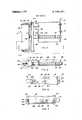
- FIG. 7is an elevation view of the latch mechanism
- Copying devices for use with elongated film websgenerally guide the web along a roller, belt and roller or multiple belt guide system. Often, belt tracking problems develop in the system using guide belts. Complex belt adjustment servo systems using belt edge de tectors, etc., are required to obtain consistent tracking. These systems are complex and expensive and often prove unreliable.
- Another object of this inventionis to provide a simple and reliable copier for individual microfiche.
- Still another object of this inventionis to provide an improved tracing adjustment arrangement for a film carrying belt.
- a microfiche copierwhich makes copies of individual microfiche on heat developable vesicular film.
- a single beltis provided to carry a sandwich of original and copy film through an exposure station, returns the sandwich to the operator, then carries the copy film through a heat-development station.
- a simple and effective belt tracking adjustment meansis provided utilizing a guide roller which is adjustable in two planes to maintain the tracking .path of a wide belt constant through a system of unflanged rollers.
- the adjustment systemalso serves to tension the belt system and includes a latch means for relaxing tension during belt removal and replacement.
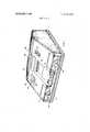
- FIG. Iis a perspective ⁇ view of a microfiche duplicator according to this invention.
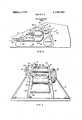
- FIG. 2is a schematic elevation view illustrating the general layout and operation of the duplicator
- FIG. 3is a perspective view of the duplicator with cover removed
- FIG. 4is a plan view of the film carrying belt tracking adjustment means
- FIG. 5is an elevation view showing the right side of the adjustment means partly in section taken on line 5:5 of FIG. 4;
- FIG. 6is sectional view taken on line 6:6 in FIG. 4;
- FIG. 1there is seen a microfiche duplicator enclosed within a housing or cover 10 mounted on a base 12.
- Two storage compartments l4 and 16are provided in'which original microfiche to be duplicated and unexposed copy film may be stored.
- Hinged covers 18 and 20are provided to cover compartments I4 and 16, respectively.
- a power switch 22is provided which turns on blowers, film drive, exposure lamp, developer lamp (which are described below) andpower indicator lamp 24.
- An operate switch 26is provided to switch the system between the print mode where the blowers, film drive and lamps are fully operating for film duplication and a standby mode in which the exposure lamp stays on, the developer lamp stays partially on and the film drive is turnedoff, but the system is ready for operation without a warm-up period.
- the desired exposure levelis set by rotating dial 28.
- An initialexposure level'is selectedon a l-l0 scale ac-' tween through which actinic radiation passes to the copy film. Since the film moves at constantspeed, total exposure is regulated by varying this gap, to vary the length of time the film is exposed.
- the operating mechanism within the duplicatorbasically consists of a wide, filrn transporting belt 36 entrained around a number of rollers.
- a conventional drive motor(not shown) operatively copy film are removed from compartments l4 and 16,
- the exposed copy filmis separated from the original and is inserted into developer entrance 48 (as seen in FIG. 1).
- the copy filmfollows the path indicated by arrows 50 in FIG. 2 through a development station including a heat development cylinder 52, then out to developed film tray 54.
- Belt 36passes along a cooling drum 56 after the heat development station to return the belt to approximately room temperature.
- the arrangement of the belt and guide meansis further shown in FIG. 3.
- the various rollers carrying belt 36, the exposure cylinder 44, the heat development cylinder 55, etc.,are journaled on two main side walls 58 and 60 which are secured to base 12.
- the frontmost guide roller 62is mounted on a retractable adjustment assembly, generally designated 64, shown in detail in FIGS. 4-6.
- Various drive componentssuch as a drive motor to drive belt 36, a blower to direct cool air through cooling drum 56, a transformer to supply power to the heater and exposure lamp, etc., would be mounted on base 12 beside or behind side walls 58 and 60. These conventional components are not shown for drawingsimplicity and clarity.
- Exposure cylinder 44is mounted on a plurality of flanged wheels 66 which permit the cylinder to be rotated by belt 36.
- cylinder 44which is transparent to ultraviolet light are a pair of telescoping cylindrical metal sleeves having matching openings 68 and 70 in their walls.
- Wheel 28is rotatable to rotate one of these sleeves to vary the overlap of openings 68 and 70.
- the exposure of film passing the openings on belt 36 to ultraviolet light from a lamp (not shown) within the sleevesdepends upon the degree of overlap. Thus, film exposure is varied by moving wheel 28.
- a lint collecting belt 72is positioned in contact with the surface of cylinder 44.
- Belt 72is mounted on three rollers 74, 76 and 78. Since belt 72 does not move as cylinder 44 rotates, the contacting portion of belt 72 continually wipes the cylinder surface. When the dust collecting capacity of the contacting portion is reached, belt 72 is moved slightly to bring a clean portion of the belt into contact'with cylinder 44. Eventually, belt 72 is replaced with a clean belLPreferably, belt 72 has a soft, high-nap surface,
- the latent vesicular film imageis made visible by heating the film while in contact with-heat development cylinder 52.
- Cylinder 52preferably comprises a thin wall aluminum cylinder having a thin silicone rubber coating over most of its outer surface.
- problems of film adhering to heat development surfaceshave often been encountered.
- Cylinder 52can be heated to operating temperature very rapidly when power is applied, since both the tungsten filament and the thin wall of cylinder 52 have low thermal inertia.
- the wall of cylinder 52is preferably less than about 0.06 inch thick to minimize warm up time.
- the temperature of the outer surface of cylinder 52is measured and regulated by a thermister sensor which is lightly spring pressed against cylinder 52.
- a thermister sensorwhich is lightly spring pressed against cylinder 52.
- the area of thermister 75 which is in contact with cylinder 52has a low friction surface, such as a flurocarbon resin. This arrangement is preferred because thermister 75 does not rotate, eliminating electrical slip rings which otherwise would be required to connect thermister 75 to the conventional temperature control circuits (not shown).
- Belt 36may be made from any suitable low-stretch, heat resistant material.
- the beltpreferably, the belt consists of a silicone coated fabric. As discussed below, proper tracking of belt 36 over the unflanged guide rollers is assured by adjusting guide roller 62.
- This assemblyincludes a belt guiding roller 62 mounted on an axle 82 which is secured to support yoke 84. Roller 62 is preferably mounted on ball bearings (not shown) for rotation relative to axle 82.
- a narrow end 86 of main support shaft 88extends through an arcuate slot 90 (as seen in FIG. 6) in the center portion of yoke 84.
- a retaining ring assembly 92(shown only in FIG. 4) holds yoke 84 in place. Slot 90 prevents vertical relative movement between yoke 84 and shaft 88, while permitting slight relative movement in an arcuate direction during roller adjustment, as further discussed below.
- Shaft 88is secured to end block 94 which is positioned immediately adjacent to yoke 84. Shaft 88 passes through openings in end walls 96 and 98 of .tray 100. Shaft 88 is a sliding fit in these end wall openings. Preferably, a collar (not shown) of low friction material is included around each opening, in sliding contact with shaft 88.
- a guide pin 102is secured to end block 94 and projects through an arcuate slot 104 in yoke 84 and an opening in end wall 96 of tray 100.
- Slot 104permits relative arcuate movement of yoke 84 relative to pin 102 during roller adjustment, while preventing relative transverse. movement.
- Slots 90 and 104are both arcuate in shape, with the center of both lying in the plane of the lower edge of roller 62, as schematically indicated by point 91 in FIG.-6. As further detailed below, this permits roller 62 to pivot about point 91 during belt tracking adjustment.
- a compression spring 106surrounds shaft 88 within tray 100, bearing against end wall 98 and against a retaining ring 108 set in a slot in shaft 88.
- spring 106urges shaft 88 leftwardly to the position shown in FIGS. 4 and 5, until retaining ring 108 abuts end wall 96. If roller 62 is. pushed backtoward tray 100, spring 106 is compressed as ring 108 is forced away from wall 96.
- slot 110moves into latching position adjacent locking slide 112. Slide 112 is moved toward shaft 88 (as best seen in FIG. 7) until the V-shaped notch 114 in the end of slide 112 enters slot 110.
- Roller 62when released, will be held in the retracted position.
- Latching roller 62 in this retracted positionpermits belt 36 (as seen in FIG. 2) to be easily changed, since it will be in a slack condition.
- a new beltis inserted, then slide 112 is moved to release shaft 88.
- the beltshould prevent roller from entirely returning to the position shown in FIGS. 4 and 5, so that retaining ring 108 will be spaced from end wall 96.
- spring 106will continue to urge the roller assembly to the left, as seen in FIGS. 4 and 5, to maintain a constant desired tension on belt 36.
- roller 62would probably have to be skewed slightly to bring the belt back to the desired path after deviations caused by slight misalignment of other rollers. This skewing of roller 62 would result in unequal tension across the belt. It has been found, however, that proper tracking and even lateral belt tension can be achieved by adding a second roller arc adjustment which pivots the roller in a plane perpendicular to the plane of the first adjustment.
- An adjustment screw 124 in end block 94bears on flange 126 extending back from yoke 84. Extensionof screw 124 moves flange 126 downwardly (as seen in FIG. 4), causing yoke 84 and roller 80 to pivot about schematically illustrated point 91, due to theshape of arcuate slots 90 and 104, which rotatably connects end block 94 and yoke 84.
- the force of screw' 124 against flange 126is balanced by a compression spring 128 psitioned between flange 130 and end block 94 at the end of end block 94 opposite to screw 124.
- Atypical adjustment rangeis schematically illustratedby the are between lines 93 and 95 in FIG. 6.
- Adjustment of screw 124controls the lateral 'belt movement as it exits the roller without affecting the incoming position because of the locationof pivot 91. Pivot 91 is equal to a point touching the bottom center ofroller 62. The roller adjustment does not affect lateral movement of the belt 36 at the entrance to roller 62, there is a slight lateral belt shift coming back to roller 62 after the belt goes through the system of rollers due to adjustment of screw 124. Adjustment of the two screws 122 and 124 compensates for system errors while maintaining equal tension across the belt.
- a duplicator for individual microfichewhich comprises:
- a first entrance in said housingadapted to receive a sandwich made up of an individual original microfiche and a sheet of copy film;
- an exposure station within said housingadapted to expose said copy film to actinic radiation through said original film to form a latent image in said .copy film corresponding to said original film as said sandwich is transported therethrough.
- an exposed film trayat least partially outside of said housing for receiving said sandwich from said exposure station
- a development stationwithin said housing adapted to develop a visible image on said exposed copy film corresponding to said latent image as said copy film I is transported therethrough;
- a single endless belt transport meansadapted to transport said sandwich from said first opening, through said exposure station to said exposed film tray and to transport said copy film from said second opening through said development station to said developed film tray,
- said single endless belt transport meanscomprising a plurality of rollers and a wide belt entrained over said plurality of rollers, one of said rollers being adjustable and including roller adjustment means to maintain belt tracking and'tension;
- said roller adjustment meanscomprising a. a first adjustment means for moving one end of said adjustable roller in a plane containing the axis of said roller and substantially parallel to the plane of the belt as it comes in to the adjustable roller, said adjustable roller pivotable by said first adjustment means abouta point lying at the end of said adjustable roller opposite to the movable 'end;' t 1' I b. asecond adjustment means for pivoting said adjustable roller. in a plane containing the axis of said roller and substantially perpendicular to the plane'of said firstadjustment, said'second adjust- "ment means'pivoting saidadjustable rolle'r'about .a point lying substantially in the plane of thetincoming belt adjacent to the centerof the adjustable roller; and c. tensioning means urging said adjustable roller toward the belt to maintain the belt in tension,
- said adjustable rollerlocated immediately adjacent to said first opening and engaging the belt over sub- .vary the quantity of ultraviolet radiation reaching said sandwich.
- the duplicator according to claim 1further including an air cooled drum means adapted to contact said belt to cool said belt after said belt leaves said developed film tray and before said belt reaches said first opening.
Landscapes
- Physics & Mathematics (AREA)
- General Physics & Mathematics (AREA)
- Photographic Developing Apparatuses (AREA)
Abstract
Description
United States Patent 1191 Maxfield et al.
l l MICROFICHE DUPLICATOR '[75 l Inventors: Frank L. Maxfield, La Mesa;
Roger B. Trimble, San Diego.
[2]] 'Appl. No.: 224,100
[52] US. Cl 355/106, 355/104, 355/108,
355/110 [51] Int. Cl. G03b 27/30 [58] Field of Search 355/104, 106, 108,
[56] References Cited 3,749,491 1451 July 31, 1973 3,379,112 4/1968 Cranskens 355 110 3,438,706 4 1969 Tanaka et a1. 355/11 4 3,551,049 12/1970 'Limberger et al. 355 110 X 3,658,418 4/1972 Mastroianni et al 355/104 X FOREIGN PATENTS 0R APPLICATIONS 915,337 1/1963 Great Britain 355/106 133,674 10 1952 Netherlands 355 110 Primary Examiner-Samuel S. Matthews Assistant Examiner-Richard M. Sheer Atlomey.lohn R. Duncan [5 7] ABSTRACT A device for duplicating individual microfiche onto heat developable vesicular film is described. This device utilizes a single drive system driving a single belt to first carry the original and copy films through an ex- UNITED STATES PATENTS posure station and then to carry the copy film alone 951 52 3 1934 S 355 0 through a heat development station. A simple and efg 411951 l 354110 fective adjustment system is provided to assure proper 2 641 980I 6/1953 Brunt 1:21.... 1:: 355/106 tracking and peratin the drive 2,983,210 5/1961 Bari], Jr. et a1... 355/106 5 l 7 D 3,077,316 2 1963 Wells et a1 3551110 x C 3,120,793 2/1964 Baglow et al. 355/109 D E VE LO PM EN T PATH 504 4 '42 i EXPOSURE 76 74 42 a a i 62 as. I
EXPOSURE 1 PATENTED JUL 31 I975 SHEET 1 U? 3 PAIENTEUJUL31 W 3.149.491
. SHEU 2 BF 3DEVELOPMENT PATH 42 ExPosuRE FIG.3
MICROFICHE DUPLICATOR BACKGROUND OF THE INVENTION This invention relates to image duplication and, more specifically, to devices for duplicating individual microfiche images.
Recently, reduced-size copies of test material, either on roll microfilm or microfiche, have come into widespread use. Micro-images are generally produced on original silver halide film either by means of a camera photographing a printed page or photographing an image on the face of a cathode ray tube in computer output microfilming equipment.
Microfiche have come to be one of the most convenient forms for recording such information. A microfiche is a sheet or card of film bearing rows and columns of reduced images. Typical microfiche have dimensions of about 4 by 6 inches and are produced in sequence on a long roll of film. Where duplicates are required, the original roll is brought into contact with a roll of copy film, such as heat developable vesicular film, diazo film or silver halide film. The sequence of images is copied, and individual microfiche are cut from the roll.
Problems arise, however, where single copies are required of single microfiche after they have been cut from'the roll. Most microfiche copiers require the original to be part of a long web which is threadable through a copying device. These devices generally cannot copy individual microfiche.
I and FIG. 7 is an elevation view of the latch mechanism,
Copying devices for use with elongated film webs generally guide the web along a roller, belt and roller or multiple belt guide system. Often, belt tracking problems develop in the system using guide belts. Complex belt adjustment servo systems using belt edge de tectors, etc., are required to obtain consistent tracking. These systems are complex and expensive and often prove unreliable.
Attempts to copy individual microfiche in manually operated contact printers such as are used in conventional photographic printing generally produce copies of poor quality. Manual printing is both slowand difficult, producing copies of irregular quality.- I Thus, there is a continuing need for improved microfiche copiers capable of. rapidly copying individual microfiche without the needfor complex manual chemical processing steps.
SUMMARY OF THE INVENTION It is, therefore, an object of this invention to provide a microfiche copier overcoming the above noted problems.
Another object of this invention is to provide a simple and reliable copier for individual microfiche.
Still another object of this invention is to provide an improved tracing adjustment arrangement for a film carrying belt.
The above objects, and others, are accomplished in accordance with this invention by a microfiche copier which makes copies of individual microfiche on heat developable vesicular film. A single belt is provided to carry a sandwich of original and copy film through an exposure station, returns the sandwich to the operator, then carries the copy film through a heat-development station. A simple and effective belt tracking adjustment means is provided utilizing a guide roller which is adjustable in two planes to maintain the tracking .path of a wide belt constant through a system of unflanged rollers. The adjustment system also serves to tension the belt system and includes a latch means for relaxing tension during belt removal and replacement.
BRIEF DESCRIPTION OF THE DRAWING Details of the invention, and of preferred embodiments thereof, will be further understood upon reference to the drawing, wherein:
FIG. I is a perspective {view of a microfiche duplicator according to this invention; 1
FIG. 2 is a schematic elevation view illustrating the general layout and operation of the duplicator;
FIG. 3 is a perspective view of the duplicator with cover removed;
FIG. 4 is a plan view of the film carrying belt tracking adjustment means;
FIG. 5 is an elevation view showing the right side of the adjustment means partly in section taken on line 5:5 of FIG. 4;
FIG. 6 is sectional view taken on line 6:6 in FIG. 4;
taken from the right side of FIG. 4.
DETAILED DESCRIPTION OF THE INVENTION Referring now to FIG. 1, there is seen a microfiche duplicator enclosed within a housing or cover 10 mounted on abase 12. Two storage compartments l4 and 16 are provided in'which original microfiche to be duplicated and unexposed copy film may be stored. Hinged covers 18 and 20 are provided to cover compartments I4 and 16, respectively.
Apower switch 22 is provided which turns on blowers, film drive, exposure lamp, developer lamp (which are described below)andpower indicator lamp 24. An operateswitch 26 is provided to switch the system between the print mode where the blowers, film drive and lamps are fully operating for film duplication and a standby mode in which the exposure lamp stays on, the developer lamp stays partially on and the film drive is turnedoff, but the system is ready for operation without a warm-up period.
The desired exposure level is set by rotatingdial 28.
An initialexposure level'is selectedon a l-l0 scale ac-' tween through which actinic radiation passes to the copy film. Since the film moves at constantspeed, total exposure is regulated by varying this gap, to vary the length of time the film is exposed.
As seen in FIG. 2, the operating mechanism within the duplicator basically consists of a wide,filrn transporting belt 36 entrained around a number of rollers.
A conventional drive motor (not shown) operatively copy film are removed from compartments l4 and 16,
are sandwiched in emulsion-to-emulsion contact with the original on top and are fed into exposure entrance 40 (as seen in FIG. 1). The sandwich iscarred bybelt 36 along the path indicated by arrows in FIG. 2
through an exposure station including anexposure cylinder 44, then out into exposedfilm tray 46.
The exposed copy film is separated from the original and is inserted into developer entrance 48 (as seen in FIG. 1). The copy film follows the path indicated byarrows 50 in FIG. 2 through a development station including aheat development cylinder 52, then out to developedfilm tray 54.Belt 36 passes along acooling drum 56 after the heat development station to return the belt to approximately room temperature.
The arrangement of the belt and guide means is further shown in FIG. 3. The variousrollers carrying belt 36, theexposure cylinder 44, the heat development cylinder 55, etc., are journaled on twomain side walls base 12. Thefrontmost guide roller 62 is mounted on a retractable adjustment assembly, generally designated 64, shown in detail in FIGS. 4-6.
Various drive components, such as a drive motor to drivebelt 36, a blower to direct cool air through coolingdrum 56, a transformer to supply power to the heater and exposure lamp, etc., would be mounted onbase 12 beside or behindside walls
Since dust which may enter with the original film/- copy film sandwich may deposit onexposure cylinder 44 and degrade image quality, alint collecting belt 72 is positioned in contact with the surface ofcylinder 44.
such as velvet.
The latent vesicular film image is made visible by heating the film while in contact with-heat development cylinder 52.Cylinder 52 preferably comprises a thin wall aluminum cylinder having a thin silicone rubber coating over most of its outer surface. In the past, problems of film adhering to heat development surfaces have often been encountered. Surprisingly, it has been found that lightly grinding or abrading a silicone rubber surface will substantially eliminate these adhesion within a slender quartz tube, is attached to sidewalls 58 and 60 and does not rotate withcylinder 52, thus eliminating slip-rings and the attendant complexity.Cylinder 52 can be heated to operating temperature very rapidly when power is applied, since both the tungsten filament and the thin wall ofcylinder 52 have low thermal inertia. The wall ofcylinder 52 is preferably less than about 0.06 inch thick to minimize warm up time.
The temperature of the outer surface ofcylinder 52 is measured and regulated by a thermister sensor which is lightly spring pressed againstcylinder 52. Preferably, the area ofthermister 75 which is in contact withcylinder 52 has a low friction surface, such as a flurocarbon resin. This arrangement is preferred becausethermister 75 does not rotate, eliminating electrical slip rings which otherwise would be required to connectthermister 75 to the conventional temperature control circuits (not shown).
Details of the adjustment means 64 are shown in FIGS. 4-7. This assembly includes abelt guiding roller 62 mounted on anaxle 82 which is secured to supportyoke 84.Roller 62 is preferably mounted on ball bearings (not shown) for rotation relative toaxle 82.
Anarrow end 86 ofmain support shaft 88 extends through an arcuate slot 90 (as seen in FIG. 6) in the center portion ofyoke 84. A retaining ring assembly 92 (shown only in FIG. 4) holdsyoke 84 in place. Slot 90 prevents vertical relative movement betweenyoke 84 andshaft 88, while permitting slight relative movement in an arcuate direction during roller adjustment, as further discussed below.
To prevent rotation of the assembly ofshaft 88 andend block 94 relative totray 100, aguide pin 102 is secured to endblock 94 and projects through anarcuate slot 104 inyoke 84 and an opening inend wall 96 oftray 100. Slot 104 permits relative arcuate movement ofyoke 84 relative to pin 102 during roller adjustment, while preventing relative transverse. movement.Slots 90 and 104 are both arcuate in shape, with the center of both lying in the plane of the lower edge ofroller 62, as schematically indicated bypoint 91 in FIG.-6. As further detailed below, this permitsroller 62 to pivot aboutpoint 91 during belt tracking adjustment.
Acompression spring 106 surroundsshaft 88 withintray 100, bearing againstend wall 98 and against a retainingring 108 set in a slot inshaft 88. Thus,spring 106 urgesshaft 88 leftwardly to the position shown in FIGS. 4 and 5, until retainingring 108 abutsend wall 96. Ifroller 62 is. pushedbacktoward tray 100,spring 106 is compressed asring 108 is forced away fromwall 96. Asend block 94 approachesend wall 96,slot 110 moves into latching positionadjacent locking slide 112.Slide 112 is moved toward shaft 88 (as best seen in FIG. 7) until the V-shapednotch 114 in the end ofslide 112 entersslot 110.Roller 62, when released, will be held in the retracted position. A pair ofcap screws support slide 112 for movement as described. Latchingroller 62 in this retracted position permits belt 36 (as seen in FIG. 2) to be easily changed, since it will be in a slack condition. A new belt is inserted, then slide 112 is moved to releaseshaft 88. In use, with a belt in place, the belt should prevent roller from entirely returning to the position shown in FIGS. 4 and 5, so that retainingring 108 will be spaced fromend wall 96. Thus,spring 106 will continue to urge the roller assembly to the left, as seen in FIGS. 4 and 5, to maintain a constant desired tension onbelt 36.
The major influence on tracking with wide belts is the angle at which the belt approaches the roller. A belt led over a roller at various angles will move toward a point atwhich the approach angle is 90. Adjustment ofscrew 122 movesaxle 82, so thatroller 62 pivots about a point schematically indicated at 123 in FIG. 4 whereaxle 82 engages the opposite side ofyoke 84. This serves to orientroller 62 at right angles to the incoming ,belt, to assure central tracking overroller 62. However,
ifscrew 122 is used alone to compensate for dimensional errors and manufacturing tolerances in the mounting of other rollers in the system,roller 62 would probably have to be skewed slightly to bring the belt back to the desired path after deviations caused by slight misalignment of other rollers. This skewing ofroller 62 would result in unequal tension across the belt. It has been found, however, that proper tracking and even lateral belt tension can be achieved by adding a second roller arc adjustment which pivots the roller in a plane perpendicular to the plane of the first adjustment.
Anadjustment screw 124 inend block 94 bears onflange 126 extending back fromyoke 84.Extensionof screw 124 moves flange 126 downwardly (as seen in FIG. 4), causingyoke 84 and roller 80 to pivot about schematically illustratedpoint 91, due to theshape ofarcuate slots 90 and 104, which rotatably connectsend block 94 andyoke 84. The force of screw' 124 againstflange 126 is balanced by acompression spring 128 psitioned betweenflange 130 and endblock 94 at the end ofend block 94 opposite to screw 124. Atypical adjustment range is schematically illustratedby the are betweenlines
Adjustment ofscrew 124 controls the lateral 'belt movement as it exits the roller without affecting the incoming position because of thelocationof pivot 91.Pivot 91 is equal to a point touching thebottom center ofroller 62. The roller adjustment does not affect lateral movement of thebelt 36 at the entrance toroller 62, there is a slight lateral belt shift coming back toroller 62 after the belt goes through the system of rollers due to adjustment ofscrew 124. Adjustment of the twoscrews
While specific arrangements and locations of components have been described in the above description of a preferred embodiment, these may be varied where suitable within the scope of this invention. For examplc, the locations ofscrew 124 andspring 128 could be reversed, if desired.
Other variations, applications and ramifications of the invention will occur to those skilled in the art upon reading this disclosure. These are intended to be in- 6 cluded within the scope of the invention, as defined in the appended claims.
We claim: 1. A duplicator for individual microfiche which comprises:
a housing;
a first entrance in said housing adapted to receive a sandwich made up of an individual original microfiche and a sheet of copy film;
an exposure station within said housing adapted to expose said copy film to actinic radiation through said original film to form a latent image in said .copy film corresponding to said original film as said sandwich is transported therethrough.
an exposed film tray at least partially outside of said housing for receiving said sandwich from said exposure station;
a second entrance in said housing for receiving a sheet of exposed copy film;
a development station within said housing adapted to develop a visible image on said exposed copy film corresponding to said latent image as said copy film I is transported therethrough;
a developed film tray at least partially outside of said housing for receiving said'copy film from said development station; and
a single endless belt transport means adapted to transport said sandwich from said first opening, through said exposure station to said exposed film tray and to transport said copy film from said second opening through said development station to said developed film tray,
said single endless belt transport means comprising a plurality of rollers and a wide belt entrained over said plurality of rollers, one of said rollers being adjustable and including roller adjustment means to maintain belt tracking and'tension;
said roller adjustment means comprising a. a first adjustment means for moving one end of said adjustable roller in a plane containing the axis of said roller and substantially parallel to the plane of the belt as it comes in to the adjustable roller, said adjustable roller pivotable by said first adjustment means abouta point lying at the end of said adjustable roller opposite to the movable 'end;' t 1' I b. asecond adjustment means for pivoting said adjustable roller. in a plane containing the axis of said roller and substantially perpendicular to the plane'of said firstadjustment, said'second adjust- "ment means'pivoting saidadjustable rolle'r'about .a point lying substantially in the plane of thetincoming belt adjacent to the centerof the adjustable roller; and c. tensioning means urging said adjustable roller toward the belt to maintain the belt in tension,
said adjustable roller located immediately adjacent to said first opening and engaging the belt over sub- .vary the quantity of ultraviolet radiation reaching said sandwich.
means to bring said copy film into contact with said heated cylinder as said copy film is transported through saiddevelopment stations 5. The duplicator according to claim 1 further including an air cooled drum means adapted to contact said belt to cool said belt after said belt leaves said developed film tray and before said belt reaches said first opening.
1r :0- :iin t
Claims (5)
1. A duplicator for individual microfiche which comprises: a housing; a first entrance in said housing adapted to receive a sandwich made up of an individual original microfiche and a sheet of copy film; an exposure station within said housing adapted to expose said copy film to actinic radiation through said original film to form a latent image in said copy film corresponding to said original film as said sandwich is transported therethrough. an exposed film tray at least partially outside of said housing for receiving said sandwich from said exposure station; a second entrance in said housing for receiving a sheet of exposed copy film; a development station within said housing adapted to develop a visible image on said exposed copy film corresponding to said latent image as said copy film is transported therethrough; a developed film tray at least partially outside of said housing for receiving said copy film from said development station; and a single endless belt transport means adapted to transport said sandwich from said first opening, through said exposure station to said exposed film tray and to transport said copy film from said second opening through said development station to said developed film tray, said single endless belt transport means comprising a plurality of rollers and a wide belt entrained over said plurality of rollers, one of said rollers being adjustable and including roller adjustment means to maintain belt tracking and tension; said roller adjustment means comprising a. a first adjustment means for moving one end of said adjustable roller in a plane containing the axis of said roller and substantially parallel to the plane of the belt as it comes in to the adJustable roller, said adjustable roller pivotable by said first adjustment means about a point lying at the end of said adjustable roller opposite to the movable end; b. a second adjustment means for pivoting said adjustable roller in a plane containing the axis of said roller and substantially perpendicular to the plane of said first adjustment, said second adjustment means pivoting said adjustable roller about a point lying substantially in the plane of the incoming belt adjacent to the center of the adjustable roller; and c. tensioning means urging said adjustable roller toward the belt to maintain the belt in tension, said adjustable roller located immediately adjacent to said first opening and engaging the belt over substantially one-half of the roller circumference.
2. The duplicator according to claim 1 wherein said exposure station comprises a source of ultraviolet radiation within an ultraviolet-transparent exposure cylinder which is rotatable by said belt and sandwich moving through the exposure station, and means to selectively vary the quantity of ultraviolet radiation reaching said sandwich.
3. The duplicator according to claim 2 further including a movable cleaning belt in contact with a portion of the surface of said exposure cylinder whereby solid particles are wiped from the surface as said exposure cylinder is rotated, and means permitting fresh portions of said cleaning belt to be brought into contact with said exposure cylinder surface.
4. The duplicator according to claim 1 wherein said development station includes a heated cylinder and means to bring said copy film into contact with said heated cylinder as said copy film is transported through said development station.
5. The duplicator according to claim 1 further including an air cooled drum means adapted to contact said belt to cool said belt after said belt leaves said developed film tray and before said belt reaches said first opening.
Applications Claiming Priority (1)
| Application Number | Priority Date | Filing Date | Title |
|---|---|---|---|
| US22410072A | 1972-02-07 | 1972-02-07 |
Publications (1)
| Publication Number | Publication Date |
|---|---|
| US3749491Atrue US3749491A (en) | 1973-07-31 |
Family
ID=22839279
Family Applications (1)
| Application Number | Title | Priority Date | Filing Date |
|---|---|---|---|
| US00224100AExpired - LifetimeUS3749491A (en) | 1972-02-07 | 1972-02-07 | Microfiche duplicator |
Country Status (1)
| Country | Link |
|---|---|
| US (1) | US3749491A (en) |
Cited By (29)
| Publication number | Priority date | Publication date | Assignee | Title |
|---|---|---|---|---|
| US4097147A (en)* | 1977-06-01 | 1978-06-27 | Portewig J Milton | Print machine frame |
| US4176949A (en)* | 1978-08-03 | 1979-12-04 | Burgess Industries, Inc. | Microfiche exposer |
| EP0117620A1 (en)* | 1983-01-31 | 1984-09-05 | Tektronix, Inc. | Improved thermal development apparatus for thermal development of a photographic medium |
| US4724469A (en)* | 1986-03-14 | 1988-02-09 | Fuji Photo Film Co., Ltd. | Image recording apparatus |
| US4801979A (en)* | 1987-12-23 | 1989-01-31 | Innovative Technology, Inc. | Device for copying microfiche |
| US5333879A (en)* | 1993-02-17 | 1994-08-02 | Barnes Thomas D | Target board for bag pitching game |
| US20030076549A1 (en)* | 2001-10-22 | 2003-04-24 | Cheung Nigel M-F | Utility document lid for imaging devices |
| US8405563B2 (en) | 2006-01-14 | 2013-03-26 | Research In Motion Rf, Inc. | Adaptively tunable antennas incorporating an external probe to monitor radiated power |
| US8490236B2 (en) | 2010-08-11 | 2013-07-23 | Telebrands Corp. | Combination sticky roller and brush |
| US9020446B2 (en) | 2009-08-25 | 2015-04-28 | Blackberry Limited | Method and apparatus for calibrating a communication device |
| US9119152B2 (en) | 2007-05-07 | 2015-08-25 | Blackberry Limited | Hybrid techniques for antenna retuning utilizing transmit and receive power information |
| US9130543B2 (en) | 2006-11-08 | 2015-09-08 | Blackberry Limited | Method and apparatus for adaptive impedance matching |
| US9231643B2 (en) | 2011-02-18 | 2016-01-05 | Blackberry Limited | Method and apparatus for radio antenna frequency tuning |
| US9419581B2 (en) | 2006-11-08 | 2016-08-16 | Blackberry Limited | Adaptive impedance matching apparatus, system and method with improved dynamic range |
| US9431990B2 (en) | 2000-07-20 | 2016-08-30 | Blackberry Limited | Tunable microwave devices with auto-adjusting matching circuit |
| US9450637B2 (en) | 2010-04-20 | 2016-09-20 | Blackberry Limited | Method and apparatus for managing interference in a communication device |
| US9548716B2 (en) | 2010-03-22 | 2017-01-17 | Blackberry Limited | Method and apparatus for adapting a variable impedance network |
| US9671765B2 (en) | 2012-06-01 | 2017-06-06 | Blackberry Limited | Methods and apparatus for tuning circuit components of a communication device |
| US9698758B2 (en) | 2008-09-24 | 2017-07-04 | Blackberry Limited | Methods for tuning an adaptive impedance matching network with a look-up table |
| US9716311B2 (en) | 2011-05-16 | 2017-07-25 | Blackberry Limited | Method and apparatus for tuning a communication device |
| US9768810B2 (en) | 2012-12-21 | 2017-09-19 | Blackberry Limited | Method and apparatus for adjusting the timing of radio antenna tuning |
| US9853622B2 (en) | 2006-01-14 | 2017-12-26 | Blackberry Limited | Adaptive matching network |
| US9941910B2 (en) | 2012-07-19 | 2018-04-10 | Blackberry Limited | Method and apparatus for antenna tuning and power consumption management in a communication device |
| US10003393B2 (en) | 2014-12-16 | 2018-06-19 | Blackberry Limited | Method and apparatus for antenna selection |
| US10163574B2 (en) | 2005-11-14 | 2018-12-25 | Blackberry Limited | Thin films capacitors |
| USRE47412E1 (en) | 2007-11-14 | 2019-05-28 | Blackberry Limited | Tuning matching circuits for transmitter and receiver bands as a function of the transmitter metrics |
| US10404295B2 (en) | 2012-12-21 | 2019-09-03 | Blackberry Limited | Method and apparatus for adjusting the timing of radio antenna tuning |
| US10624091B2 (en) | 2011-08-05 | 2020-04-14 | Blackberry Limited | Method and apparatus for band tuning in a communication device |
| US10659088B2 (en) | 2009-10-10 | 2020-05-19 | Nxp Usa, Inc. | Method and apparatus for managing operations of a communication device |
Citations (11)
| Publication number | Priority date | Publication date | Assignee | Title |
|---|---|---|---|---|
| US1951952A (en)* | 1930-10-24 | 1934-03-20 | Sullivan Harry Hewes | Printing machine for sensitized material |
| US2548936A (en)* | 1946-10-31 | 1951-04-17 | Ozalid Co Ltd | Photocopying machine |
| US2641980A (en)* | 1947-04-04 | 1953-06-16 | Pease C F Co | Cylindrical photoprinting machine |
| US2983210A (en)* | 1954-04-12 | 1961-05-09 | Kalvar Corp | Contact printing apparatus |
| GB915337A (en)* | 1960-02-16 | 1963-01-09 | Dietzgen Co Eugene | Photographic printing process and apparatus |
| US3077316A (en)* | 1960-06-07 | 1963-02-12 | Bruning Charles Co Inc | Sheet rolling device |
| US3120793A (en)* | 1958-06-16 | 1964-02-11 | Block & Anderson Ltd | Photo copying machines |
| US3379112A (en)* | 1964-07-15 | 1968-04-23 | Lumoprint Zindler Kg | Irradiation device and more particularly exposure device |
| US3438706A (en)* | 1966-10-07 | 1969-04-15 | Canon Kk | Electrophotographic device |
| US3551049A (en)* | 1963-03-14 | 1970-12-29 | Lumoprint Zindler Kg | Photographic method for producing a copy and apparatus for carrying out this method |
| US3658418A (en)* | 1969-12-31 | 1972-04-25 | Gaf Corp | Printer multi-belt tension control |
- 1972
- 1972-02-07USUS00224100Apatent/US3749491A/ennot_activeExpired - Lifetime
Patent Citations (11)
| Publication number | Priority date | Publication date | Assignee | Title |
|---|---|---|---|---|
| US1951952A (en)* | 1930-10-24 | 1934-03-20 | Sullivan Harry Hewes | Printing machine for sensitized material |
| US2548936A (en)* | 1946-10-31 | 1951-04-17 | Ozalid Co Ltd | Photocopying machine |
| US2641980A (en)* | 1947-04-04 | 1953-06-16 | Pease C F Co | Cylindrical photoprinting machine |
| US2983210A (en)* | 1954-04-12 | 1961-05-09 | Kalvar Corp | Contact printing apparatus |
| US3120793A (en)* | 1958-06-16 | 1964-02-11 | Block & Anderson Ltd | Photo copying machines |
| GB915337A (en)* | 1960-02-16 | 1963-01-09 | Dietzgen Co Eugene | Photographic printing process and apparatus |
| US3077316A (en)* | 1960-06-07 | 1963-02-12 | Bruning Charles Co Inc | Sheet rolling device |
| US3551049A (en)* | 1963-03-14 | 1970-12-29 | Lumoprint Zindler Kg | Photographic method for producing a copy and apparatus for carrying out this method |
| US3379112A (en)* | 1964-07-15 | 1968-04-23 | Lumoprint Zindler Kg | Irradiation device and more particularly exposure device |
| US3438706A (en)* | 1966-10-07 | 1969-04-15 | Canon Kk | Electrophotographic device |
| US3658418A (en)* | 1969-12-31 | 1972-04-25 | Gaf Corp | Printer multi-belt tension control |
Cited By (50)
| Publication number | Priority date | Publication date | Assignee | Title |
|---|---|---|---|---|
| US4097147A (en)* | 1977-06-01 | 1978-06-27 | Portewig J Milton | Print machine frame |
| US4176949A (en)* | 1978-08-03 | 1979-12-04 | Burgess Industries, Inc. | Microfiche exposer |
| EP0117620A1 (en)* | 1983-01-31 | 1984-09-05 | Tektronix, Inc. | Improved thermal development apparatus for thermal development of a photographic medium |
| US4724469A (en)* | 1986-03-14 | 1988-02-09 | Fuji Photo Film Co., Ltd. | Image recording apparatus |
| US4801979A (en)* | 1987-12-23 | 1989-01-31 | Innovative Technology, Inc. | Device for copying microfiche |
| US5333879A (en)* | 1993-02-17 | 1994-08-02 | Barnes Thomas D | Target board for bag pitching game |
| US9768752B2 (en) | 2000-07-20 | 2017-09-19 | Blackberry Limited | Tunable microwave devices with auto-adjusting matching circuit |
| US9948270B2 (en) | 2000-07-20 | 2018-04-17 | Blackberry Limited | Tunable microwave devices with auto-adjusting matching circuit |
| US9431990B2 (en) | 2000-07-20 | 2016-08-30 | Blackberry Limited | Tunable microwave devices with auto-adjusting matching circuit |
| US20030076549A1 (en)* | 2001-10-22 | 2003-04-24 | Cheung Nigel M-F | Utility document lid for imaging devices |
| US10163574B2 (en) | 2005-11-14 | 2018-12-25 | Blackberry Limited | Thin films capacitors |
| US10177731B2 (en) | 2006-01-14 | 2019-01-08 | Blackberry Limited | Adaptive matching network |
| US9853622B2 (en) | 2006-01-14 | 2017-12-26 | Blackberry Limited | Adaptive matching network |
| US8405563B2 (en) | 2006-01-14 | 2013-03-26 | Research In Motion Rf, Inc. | Adaptively tunable antennas incorporating an external probe to monitor radiated power |
| US10050598B2 (en) | 2006-11-08 | 2018-08-14 | Blackberry Limited | Method and apparatus for adaptive impedance matching |
| US9130543B2 (en) | 2006-11-08 | 2015-09-08 | Blackberry Limited | Method and apparatus for adaptive impedance matching |
| US10020828B2 (en) | 2006-11-08 | 2018-07-10 | Blackberry Limited | Adaptive impedance matching apparatus, system and method with improved dynamic range |
| US9419581B2 (en) | 2006-11-08 | 2016-08-16 | Blackberry Limited | Adaptive impedance matching apparatus, system and method with improved dynamic range |
| US9722577B2 (en) | 2006-11-08 | 2017-08-01 | Blackberry Limited | Method and apparatus for adaptive impedance matching |
| US9119152B2 (en) | 2007-05-07 | 2015-08-25 | Blackberry Limited | Hybrid techniques for antenna retuning utilizing transmit and receive power information |
| USRE47412E1 (en) | 2007-11-14 | 2019-05-28 | Blackberry Limited | Tuning matching circuits for transmitter and receiver bands as a function of the transmitter metrics |
| USRE48435E1 (en) | 2007-11-14 | 2021-02-09 | Nxp Usa, Inc. | Tuning matching circuits for transmitter and receiver bands as a function of the transmitter metrics |
| US9698758B2 (en) | 2008-09-24 | 2017-07-04 | Blackberry Limited | Methods for tuning an adaptive impedance matching network with a look-up table |
| US9020446B2 (en) | 2009-08-25 | 2015-04-28 | Blackberry Limited | Method and apparatus for calibrating a communication device |
| US10659088B2 (en) | 2009-10-10 | 2020-05-19 | Nxp Usa, Inc. | Method and apparatus for managing operations of a communication device |
| US10615769B2 (en) | 2010-03-22 | 2020-04-07 | Blackberry Limited | Method and apparatus for adapting a variable impedance network |
| US9742375B2 (en) | 2010-03-22 | 2017-08-22 | Blackberry Limited | Method and apparatus for adapting a variable impedance network |
| US9608591B2 (en) | 2010-03-22 | 2017-03-28 | Blackberry Limited | Method and apparatus for adapting a variable impedance network |
| US10263595B2 (en) | 2010-03-22 | 2019-04-16 | Blackberry Limited | Method and apparatus for adapting a variable impedance network |
| US9548716B2 (en) | 2010-03-22 | 2017-01-17 | Blackberry Limited | Method and apparatus for adapting a variable impedance network |
| US9941922B2 (en) | 2010-04-20 | 2018-04-10 | Blackberry Limited | Method and apparatus for managing interference in a communication device |
| US9450637B2 (en) | 2010-04-20 | 2016-09-20 | Blackberry Limited | Method and apparatus for managing interference in a communication device |
| US8490237B2 (en) | 2010-08-11 | 2013-07-23 | Telebrands Corp. | Combination sticky roller and brush |
| US8763190B2 (en) | 2010-08-11 | 2014-07-01 | Telebrands Corp. | Portable hair/lint roller |
| US8490236B2 (en) | 2010-08-11 | 2013-07-23 | Telebrands Corp. | Combination sticky roller and brush |
| US8590094B2 (en) | 2010-08-11 | 2013-11-26 | Telebrands Corp. | Portable hair/lint roller |
| US9698858B2 (en) | 2011-02-18 | 2017-07-04 | Blackberry Limited | Method and apparatus for radio antenna frequency tuning |
| US9935674B2 (en) | 2011-02-18 | 2018-04-03 | Blackberry Limited | Method and apparatus for radio antenna frequency tuning |
| US9231643B2 (en) | 2011-02-18 | 2016-01-05 | Blackberry Limited | Method and apparatus for radio antenna frequency tuning |
| US10979095B2 (en) | 2011-02-18 | 2021-04-13 | Nxp Usa, Inc. | Method and apparatus for radio antenna frequency tuning |
| US10218070B2 (en) | 2011-05-16 | 2019-02-26 | Blackberry Limited | Method and apparatus for tuning a communication device |
| US9716311B2 (en) | 2011-05-16 | 2017-07-25 | Blackberry Limited | Method and apparatus for tuning a communication device |
| US10624091B2 (en) | 2011-08-05 | 2020-04-14 | Blackberry Limited | Method and apparatus for band tuning in a communication device |
| US9671765B2 (en) | 2012-06-01 | 2017-06-06 | Blackberry Limited | Methods and apparatus for tuning circuit components of a communication device |
| US9941910B2 (en) | 2012-07-19 | 2018-04-10 | Blackberry Limited | Method and apparatus for antenna tuning and power consumption management in a communication device |
| US10404295B2 (en) | 2012-12-21 | 2019-09-03 | Blackberry Limited | Method and apparatus for adjusting the timing of radio antenna tuning |
| US10700719B2 (en) | 2012-12-21 | 2020-06-30 | Nxp Usa, Inc. | Method and apparatus for adjusting the timing of radio antenna tuning |
| US9768810B2 (en) | 2012-12-21 | 2017-09-19 | Blackberry Limited | Method and apparatus for adjusting the timing of radio antenna tuning |
| US10651918B2 (en) | 2014-12-16 | 2020-05-12 | Nxp Usa, Inc. | Method and apparatus for antenna selection |
| US10003393B2 (en) | 2014-12-16 | 2018-06-19 | Blackberry Limited | Method and apparatus for antenna selection |
Similar Documents
| Publication | Publication Date | Title |
|---|---|---|
| US3749491A (en) | Microfiche duplicator | |
| US3672765A (en) | Apparatus for making two-sided copies from two images on an original | |
| US3694073A (en) | Method for duplexing | |
| US3572924A (en) | Copying apparatus | |
| US3500694A (en) | Belt tracking system | |
| US3049968A (en) | Xerographic reproduction apparatus | |
| US3685905A (en) | Combined document feed and book copying apparatus | |
| US3500734A (en) | Photographic recorder and processor | |
| US3674354A (en) | Microfilm viewer-printer | |
| US3652157A (en) | Microfilm projection apparatus | |
| US3680956A (en) | Apparatus for controlling contrast during reproduction of photographic images | |
| US3685906A (en) | Apparatus and means for making duplicates of a microfilm original | |
| US3264961A (en) | Photographic apparatus for recording, processing, and projecting data | |
| US3768904A (en) | Printing apparatus including registration control | |
| US3592539A (en) | Recording apparatus | |
| US4021110A (en) | Photocopying camera and processing device | |
| US4452524A (en) | Electrostatographic reproducing apparatus with spring loaded paper path | |
| US4903070A (en) | Image recording apparatus | |
| US3639060A (en) | Apparatus for photographically duplicating information-bearing media | |
| US3073234A (en) | Miniature reflex copy-reproducing device | |
| US3705768A (en) | Copying apparatus | |
| US3354804A (en) | Developing camera | |
| EP0447691B1 (en) | A scanning exposure device | |
| US3582207A (en) | Apparatus for making multiple copies of an image web | |
| US3813164A (en) | Film holder for making prints |
Legal Events
| Date | Code | Title | Description |
|---|---|---|---|
| AS | Assignment | Owner name:CITIBANK, V.A. Free format text:SECURITY INTEREST;ASSIGNOR:ANACOMP, INC., A IN CORP.;REEL/FRAME:004761/0669 Effective date:19870320 | |
| AS | Assignment | Owner name:ANACOMP, INC., 11550 NORTH MERIDAN STREET, CARMEL, Free format text:ASSIGNMENT OF ASSIGNORS INTEREST.;ASSIGNOR:DATAGRAPHIX, INC.;REEL/FRAME:004811/0769 Effective date:19870930 | |
| AS | Assignment | Owner name:CITIBANK, N.A.,, NEW YORK Free format text:SECURITY INTEREST;ASSIGNOR:ANACOMP, INC.;REEL/FRAME:005274/0054 Effective date:19880826 | |
| AS | Assignment | Owner name:ANACOMP, INC., A CORP. OF INDIANA Free format text:RELEASED BY SECURED PARTY;ASSIGNOR:CITIBANK, N.A.;REEL/FRAME:005635/0013 Effective date:19901029 |