US3739151A - Electronic voting machine - Google Patents
Electronic voting machineDownload PDFInfo
- Publication number
- US3739151A US3739151AUS00244609AUS3739151DAUS3739151AUS 3739151 AUS3739151 AUS 3739151AUS 00244609 AUS00244609 AUS 00244609AUS 3739151D AUS3739151D AUS 3739151DAUS 3739151 AUS3739151 AUS 3739151A
- Authority
- US
- United States
- Prior art keywords
- selection
- vote
- output signal
- receiving
- output signals
- Prior art date
- Legal status (The legal status is an assumption and is not a legal conclusion. Google has not performed a legal analysis and makes no representation as to the accuracy of the status listed.)
- Expired - Lifetime
Links
- 230000003111delayed effectEffects0.000claims1
- 101100180402Caenorhabditis elegans jun-1 geneProteins0.000description1
Images


Classifications
- G—PHYSICS
- G07—CHECKING-DEVICES
- G07C—TIME OR ATTENDANCE REGISTERS; REGISTERING OR INDICATING THE WORKING OF MACHINES; GENERATING RANDOM NUMBERS; VOTING OR LOTTERY APPARATUS; ARRANGEMENTS, SYSTEMS OR APPARATUS FOR CHECKING NOT PROVIDED FOR ELSEWHERE
- G07C13/00—Voting apparatus
Definitions
- ABSTRACTAn electronic voting machine is disclosed which accommodates for selection of one, and only one, candidate from each of two office groups.
- Electronic logic circuitryis used throughout.
- the logicfeatures redundant interlocks to assure (1) that overvoting in either office group cannot occur and (2) that a vote cannot be counted unless a selection has been made in both office groups.
- the interlocksfeature redundancy while minimizing the components needed to accommodate for large numbers of candidates in both office groups, and also a combined cancelafter vote reset arrangement which both prevents overvoting and causes reset after vote completion.
- Another feature of the systemis the use of parallel tallying devices each capable of printing out its tally, one such device being the electromechanical counters usually associated with a voting machine and which tally the votes for the individual candidates, and the other such device being an electronic accumulator which likewise counts or tallies the votes for the individual candidates.
- a print-out of the electromechanical tally and the accumulator tallyis made.
- the accumulator tally print-outis made sequentially much in the fashion of an adding machine, while the print-out of the electromechanical counters is made in one pass of a movable platen.
- the accumulatorhas the capability of providing a digital read-out of the voting at all times so that, if desired, the accumulator may be connected, along with a great number of others at different voting sites, to a central computor which may then give an instantaneous tally of the vote for an entire district, state or nation.
- Both print-outsproduce a tally sheet having type which may be be optically scanned to produce a digital output which, from a central location receiving a number of such tally sheets, may forward this digital information to a central computer, as before, at the end of a voting day.
- Other flexibilitiesare also presented by the parallel electromechanicalelectronic accumulator system.
Landscapes
- Physics & Mathematics (AREA)
- General Physics & Mathematics (AREA)
- Time Recorders, Dirve Recorders, Access Control (AREA)
- Management, Administration, Business Operations System, And Electronic Commerce (AREA)
Abstract
Description
United States Patent Moldovan, Jr. et al.
[ 1 June 12, 1973 ELECTRONIC VOTING MACHINE [75 I Inventors: Michael Terrance Moldovan, Jr, 7
Charles Jerome Lindros, both of Lakewood; Robert Dean Wescott, Lawrence Levi Anderson, both of Jamestown, all of N.Y.
[73] Assignee: AVM Corporation,.lamestown,N.Y. [22] Filed: Apr. 17, 1972 [21] Appl. No.: 244,609
Related U.S. Application Data [63] Continuation-in-part of Ser. No. 204,506, Dec. 3,
1971, abandoned.
[52] U.S. Cl. 235/54 F [51] Int. Cl G07c 13/00 [58] Field of Search. 235/51, 50 R, 50 B,
[56] References Cited UNITED STATES PATENTS 3,214,091 10/1965 Clark 235/50 3,226,018 12/1965 Railsback et al. 235/50 3,227,364 1/1966 Clark 235/50 Primary Examiner-Richard B. Wilkinson Assistant ExaminerU. Weldon Attorney-John B. Bean, Edwin T. Bean, Raymond F. Kramer et al.
[57] ABSTRACT An electronic voting machine is disclosed which accommodates for selection of one, and only one, candidate from each of two office groups. Electronic logic circuitry is used throughout. The logic features redundant interlocks to assure (1) that overvoting in either office group cannot occur and (2) that a vote cannot be counted unless a selection has been made in both office groups. The interlocks feature redundancy while minimizing the components needed to accommodate for large numbers of candidates in both office groups, and also a combined cancelafter vote reset arrangement which both prevents overvoting and causes reset after vote completion. Another feature of the system is the use of parallel tallying devices each capable of printing out its tally, one such device being the electromechanical counters usually associated with a voting machine and which tally the votes for the individual candidates, and the other such device being an electronic accumulator which likewise counts or tallies the votes for the individual candidates. At the end of a voting day, a print-out of the electromechanical tally and the accumulator tally is made. The accumulator tally print-out is made sequentially much in the fashion of an adding machine, while the print-out of the electromechanical counters is made in one pass of a movable platen. The accumulator has the capability of providing a digital read-out of the voting at all times so that, if desired, the accumulator may be connected, along with a great number of others at different voting sites, to a central computor which may then give an instantaneous tally of the vote for an entire district, state or nation. Both print-outs produce a tally sheet having type which may be be optically scanned to produce a digital output which, from a central location receiving a number of such tally sheets, may forward this digital information to a central computer, as before, at the end of a voting day. Other flexibilities are also presented by the parallel electromechanicalelectronic accumulator system.
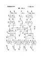
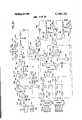
18 Claims, 27 Drawing Figures 34 96 TwoL 38 62 o l- DUMP CAND. 36 SECURITY -3 REMOTE J INTERLOCK LOG;ENTRANCE 32 EX" EXIT wo LOGIC ADDO x 94A will IE PRINTER 22 26l B 42 B2 flW0 r R 92 cool x -8: 106
| 23 8 -98 60 1 L i LOCKOJT 8O 84 m E EXPANDER ELECTRONIC l X a 24I E I Accumuma l g 86 3 Two CLEAR I g l 88 CAND. T.
58 8| 90 I04 7078L 46 5o c i'lil I 1 52 g L. REG. I m
68 w- CONTROL -76 16!J 48 1 SE urn E 'MO 5 56 I4 LOGIC CLEAR 55 O c R mm P sung: I02 I |6 111 CENTRAL COMPUTER PAIENIEnamzma 3339.151.
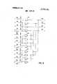
PAIENIED 3.739.151 SHEET 08 0f 25 hso hzim Pmmmwn I awn 3,739, 51
am 13m '25 FIG. H
PAIENIEB Jun 1 2 ms slm 15a: 25
PATENIED I Z SWITCH POSITION FIG. I?
Claims (18)
1. In an electronic voting machine, in combination: a plurality of candidate selection means for accepting manual selection inputs and producing electrical selection output signals corresponding thereto; a plurality of selection logic means for receiving said selection output signals and enabling a subsequent discrete counting output electrical signal for each of said selection inputs; electromechanical counter means for receiving said discrete counting output signals and separately tallying the number of times each individual candidate is selected and voted; interlock means for receiving said selection output signals and producing a vote enabling output signal in response to a certain and only said certain number of candidate selections; control logic means for receiving said vote enabling output signal to enable a vote register output signal therefrom, said vote register output signal being connected to all of said selection logic means to produce said counting output signal from any thereof enabled by said selection output signals; voter-controlled exit means for enabling said control logic means to produce said vote register output signal therefrom upon actuation of said exit means; after vote reset means having said vote register output signal as an input for producing an after vote reset signal which is delayed in time with respect to said vote register output signal; and clearing means for receiving said after vote reset signal to produce a clearing signal in response thereto, said clearing signal being connected to all of said candidate selection means to cancel any selection made thereon subsequent to tallying of the vote.
2. In an electronic voting machine as defined in claim 1 wherein said interlock means produces an overvote output signal in response to actuation of more than said certain number of candidate selections, said overvote output signal being connected to said clearing means to produce said clearing signal independently of said after vote reset signal.
3. In an electronic voting machine as defined in claim 2 wherein said interlock means produces a no selection output signal in the absence of any selection output signal thereto, said no selection output signal being connected to said after vote reset means to terminate said after vote reset signal.
4. In an electronic voting machine as defined in claim 1 wherein said interlock means produces a no selection output signal in the absence of any selection output signal thereto, said no selection output signal being connected to said after vote reset means to terminate said after vote reset signal.
5. In an electronic voting machine, in combination: a plurality of candidate selection means for accepting manual selection inputs and producing electrical selection output signals corresponding thereto; a plurality of selection logic means for receiving said selector output signals and enabling a subsequent discrete counting output electrical signal for each of said selection inputs; electromechanical counter means for receiving said discrete counting output signals and separately tallying the number of times each individual candidate is selected and voted; interlock means for receiving said selection output signals and producing a vote enabling output signal in response to a certain and only said certain number of candidate selections; control logic means for receiving said vote enabling output signal to enable a vote register output therefrom, said vote register output signal being connected to all of said selection logic means to produce said counting output signal from any thereof enabled by said selection output signals; and voter-controlled exit means for enabling said control logic means to produce said vote register output signal therefrom upon actuation of such exit means; said candidate selection means being separated into two groups, one for each of two different offices; said interlock means comprising a pair of principle interlock means for receiving the separate selection output signals of each group and expander interlock means controlled by said pair of principle interlock means, said expander interlock means having said vote enabling output signal therefrom.
6. In an electronic voting machine as defined in claim 5 including: remote control means for accepting a voting official manual input and producing an entrance output signal therefrom, said entrance output signal being connected to said control logic means to reset same.
7. In an electronic voting machine, in combination: a plurality of candidate selection means for accepting manual selection inputs and producing electrical selection output signals corresponding thereto; a plurality of selection logic means for receiving said selection output signals and enabling a subsequent discrete counting output electrical signal for each of said selection inputs; electromechanical counter means for receiving said discrete counting output signals and separately tallying the number of times each individual candidate is selected and voted; interlock means for receiving said selection output signals and producing a vote enabling output signal in response to a certain and only said certain number of candidate selections; control logic means for receiving said vote enabling output signal to enable a vote register output signal therefrom, said vote register output signal being connected to all of said selection logic means to produce said counting output signal from any thereof enabled by said selection output signals; voter-controlled exit means for enabling said control logic means to produce said vote register output signal therefrom upon actuation of such exit means; and remote control means for accepting a voting official manual input and producing an entrance output signal therefrom, said entrance output signal being connected to said control logic means to reset same.
8. In an electronic voting machine, in combination: a plurality of candidate selection means for accepting manual selection inputs and producing electrical selection output signals corresponding thereto; a plurality of selection logic means for receiving said selection output signals and enabling a subsequent discrete counting output electrical signal for each of said selection inputs; electromechanical counter means for receiving said discrete counting output signals and separately tallying the number of times each individual candidate is selected and voted; interlock means for receiving said selection output signals and producing a vote enabling output signal in response to a certain and only said certain number of candidate selections; control logic means for receiving said vote enabling output signal to enable a vote register output signal therefrom, said vote register output signal being connected to all of said selection logic means to produce said counting output signal from any thereof enabled by said selection output signals; and voter-controlled exit means for enabling said control logic means to produce said vote register output signal therefrom upon actuation of such exit means; said interlock means including a first pair of logic gates in which each gate receives a pair of said selection output signals and a second pair of logic gates each receiving a pair of vote selection output signals which are inputs to two gates of said first pair, and a further logic gate having the outputs of said second pair as inputs thereto.
9. In an electronic voting machine as defined in claim 8 wherein there are additional pairs of first and second logic gates, each having a further logic gate connected to the outputs of an associated second pair; a final pair of logic gates each having a pair of outputs from two of said further gates as inputs thereto, a second pair of logic gates each receiving a pair of outputs from a pair of further gates which are inputs to two gates of said final pair; a first output logic gate receiving the outputs of said further logic gates as inputs thereto; and a second output logic gate controlled by the outputs of all of said first pair of logic gates all of said second pair of logic gates, and said final pair of logic gates.
10. In an electronic voting machine, in combination: a plurality of candidate selection means for accepting manual selection inputs and producing electrical selection output signals corresponding thereto; a plurality of selection logic means for receiving said selection output signals and enabling a subsequent discrete counting output electrical signal for each of said selection inputs; electromechanical counter means for receiving said discrete counting output signals and separately tallying the number of times each individual candidate is selected and voted; interlock means for receiving said selection output signals and producing a vote enabling output signal in response to a certain and only said certain number of candidate selections; control logic means for receiving said vote enabling output signal to enable a vote register output signal therefrom, said vote register output signal being connected to all of said selection logic means to produce said counting output signal from any thereof enabled by said selection output signals; voter-controlled exit means for enabling said control logic means to produce said vote register output signal therefrom upon actuation of such exit means; and electronic vote count accumulating means for receiving said selection output signals and said vote register output signals electronically to accumulate the votes cast for individual candidates.
11. In an electronic voting machine as defined in claim 10 including: printer means for receiving and printing out the tally from said accumulator means.
12. In an electronic voting machine as defined in claim 11 including: security interlock means controlled by an election official for operating said printer means.
13. In an electronic voting machine as defined in claim 11 including: digit sequencer means controlled by said printer means for inserting vote count digits thereinto; register sequencer means controlled by said digit sequencer means for shifting from one candidate tally to the next when all the digits of the tally of said one candidate have been inserted into said printer means.
14. In an electronic voting machine as defined in claim 13 wherein said accumulator means includes a counter having an input each time said register sequencer means is shifted, said digit sequencer means shifting the output of said counter into said printer means for each candidate tally, whereby each candidate tally in the printer means is identified.
15. In an electronic voting machine as defined in claim 14 including: fIrst multiplexing means controlled by said register sequencer means for shifting out the tally of individual candidates in sequence; and second multiplexing means controlled by said digit sequencer means for inserting digits of each tally sequentially into said printer means.
16. In an electronic voting machine, in combination: a plurality of candidate selection means for accepting manual selection inputs and effecting selection output electrical signals corresponding thereto; logic means receiving said selection output signals for enabling a number of discrete counting output electrical signals corresponding to manual selection inputs which meet an allowable voting selection; electromechanical counter means responsive to said counting output signals for separately tallying the number of times each individual candidate is selected and voted; electronic accumulator means responsive to said counting output signals for accumulating the tally of votes cast for the individual candidates in duplication of the tallies made by said electromechanical counter means; first printing means associated with said electromechanical counter means for printing out the tallies indicated thereby; second printing means associated with said electronic accumulator means for printing out the tallies accumulated thereby; voting official-controlled first means for actuating said first printing means at the beginning of a voting day to print out the tally on said electromechanical counter means and open the voting machine for subsequent voting and said voting official-controlled first means actuates said first printing means at the end of a voting day to print out the tally on said electromechanical counter means, and closes the voting machine to further voting; voting official-controlled second means for actuating transfer the tally accumulated in said electronic accumulator means to said second printing means; and voter-controlled means for connecting those counting output signals corresponding to his vote to said electromechanical counter means and to said electronic accumulator means.
17. In an electronic voting machine as defined in claim 16 including means disabling said voting official-controlled second means until at least one vote has been recorded by the machine.
18. In an electronic voting machine as defined in claim 16 wherein said voting official-controlled first means includes a mechanical switch actuated by said first printing means in response to actuation of said voting official-controlled first means.
Applications Claiming Priority (1)
| Application Number | Priority Date | Filing Date | Title |
|---|---|---|---|
| US24460972A | 1972-04-17 | 1972-04-17 |
Publications (1)
| Publication Number | Publication Date |
|---|---|
| US3739151Atrue US3739151A (en) | 1973-06-12 |
Family
ID=22923440
Family Applications (1)
| Application Number | Title | Priority Date | Filing Date |
|---|---|---|---|
| US00244609AExpired - LifetimeUS3739151A (en) | 1972-04-17 | 1972-04-17 | Electronic voting machine |
Country Status (1)
| Country | Link |
|---|---|
| US (1) | US3739151A (en) |
Cited By (18)
| Publication number | Priority date | Publication date | Assignee | Title |
|---|---|---|---|---|
| US3847345A (en)* | 1973-03-23 | 1974-11-12 | Avm Corp | Electronic voting machine |
| US3904854A (en)* | 1973-06-18 | 1975-09-09 | Int Election Systems Corp | Automatic mechanical voting machine with electronic readout |
| US3941976A (en)* | 1974-05-13 | 1976-03-02 | Huhn M Susan | Vote recording |
| US3980864A (en)* | 1973-06-18 | 1976-09-14 | International Election Systems Corporation | Automatic mechanical voting machine with electronic readout |
| US4015106A (en)* | 1975-05-20 | 1977-03-29 | Evm Limited | Electronic voting machine |
| US4021780A (en)* | 1975-09-24 | 1977-05-03 | Narey James O | Ballot tallying system including a digital programmable read only control memory, a digital ballot image memory and a digital totals memory |
| US4025757A (en)* | 1975-01-23 | 1977-05-24 | Video Voter Inc. | Voting system |
| US4046992A (en)* | 1976-03-04 | 1977-09-06 | Mary Susan Huhn | Compact electronic voting |
| US4649264A (en)* | 1985-11-01 | 1987-03-10 | Carson Manufacturing Company, Inc. | Electronic voting machine |
| US20030034393A1 (en)* | 2000-11-20 | 2003-02-20 | Chung Kevin Kwong-Tai | Electronic voting apparatus, system and method |
| US20060169778A1 (en)* | 2000-11-20 | 2006-08-03 | Chung Kevin K | Electronic voting apparatus, system and method |
| US20060202031A1 (en)* | 2001-10-01 | 2006-09-14 | Chung Kevin K | Reader for an optically readable ballot |
| US20060255145A1 (en)* | 2001-10-01 | 2006-11-16 | Chung Kevin K | Method for reading an optically readable sheet |
| US7422150B2 (en) | 2000-11-20 | 2008-09-09 | Avante International Technology, Inc. | Electronic voting apparatus, system and method |
| US20090289115A1 (en)* | 2008-04-30 | 2009-11-26 | Kevin Kwong-Tai Chung | Optically readable marking sheet and reading apparatus and method therefor |
| US7635087B1 (en) | 2001-10-01 | 2009-12-22 | Avante International Technology, Inc. | Method for processing a machine readable ballot and ballot therefor |
| US20100252628A1 (en)* | 2009-04-07 | 2010-10-07 | Kevin Kwong-Tai Chung | Manual recount process using digitally imaged ballots |
| US20110089236A1 (en)* | 2009-10-21 | 2011-04-21 | Kevin Kwong-Tai Chung | System and method for decoding an optically readable markable sheet and markable sheet therefor |
- 1972
- 1972-04-17USUS00244609Apatent/US3739151A/ennot_activeExpired - Lifetime
Cited By (31)
| Publication number | Priority date | Publication date | Assignee | Title |
|---|---|---|---|---|
| US3847345A (en)* | 1973-03-23 | 1974-11-12 | Avm Corp | Electronic voting machine |
| US3904854A (en)* | 1973-06-18 | 1975-09-09 | Int Election Systems Corp | Automatic mechanical voting machine with electronic readout |
| US3980864A (en)* | 1973-06-18 | 1976-09-14 | International Election Systems Corporation | Automatic mechanical voting machine with electronic readout |
| US3941976A (en)* | 1974-05-13 | 1976-03-02 | Huhn M Susan | Vote recording |
| US4025757A (en)* | 1975-01-23 | 1977-05-24 | Video Voter Inc. | Voting system |
| US4015106A (en)* | 1975-05-20 | 1977-03-29 | Evm Limited | Electronic voting machine |
| US4021780A (en)* | 1975-09-24 | 1977-05-03 | Narey James O | Ballot tallying system including a digital programmable read only control memory, a digital ballot image memory and a digital totals memory |
| US4046992A (en)* | 1976-03-04 | 1977-09-06 | Mary Susan Huhn | Compact electronic voting |
| US4649264A (en)* | 1985-11-01 | 1987-03-10 | Carson Manufacturing Company, Inc. | Electronic voting machine |
| US7422150B2 (en) | 2000-11-20 | 2008-09-09 | Avante International Technology, Inc. | Electronic voting apparatus, system and method |
| US20030034393A1 (en)* | 2000-11-20 | 2003-02-20 | Chung Kevin Kwong-Tai | Electronic voting apparatus, system and method |
| US20060169778A1 (en)* | 2000-11-20 | 2006-08-03 | Chung Kevin K | Electronic voting apparatus, system and method |
| US7461787B2 (en) | 2000-11-20 | 2008-12-09 | Avante International Technology, Inc. | Electronic voting apparatus, system and method |
| US7431209B2 (en) | 2000-11-20 | 2008-10-07 | Avante International Technology, Inc. | Electronic voting apparatus, system and method |
| US7635088B2 (en) | 2001-10-01 | 2009-12-22 | Avante International Technology, Inc. | Electronic voting method and system employing a printed machine readable ballot |
| US7975920B2 (en) | 2001-10-01 | 2011-07-12 | Avante International Technology, Inc. | Electronic voting method and system employing a machine readable ballot envelope |
| US20060255145A1 (en)* | 2001-10-01 | 2006-11-16 | Chung Kevin K | Method for reading an optically readable sheet |
| US20090020606A1 (en)* | 2001-10-01 | 2009-01-22 | Kevin Kwong-Tai Chung | Electronic voting method and system employing a machine readable ballot envelope |
| US7614553B2 (en) | 2001-10-01 | 2009-11-10 | Avante International Technology, Inc. | Method for reading an optically readable sheet |
| US20070170253A1 (en)* | 2001-10-01 | 2007-07-26 | Avante International Technology, Inc. | Electronic voting method and system employing a printed machine readable ballot |
| US20060202031A1 (en)* | 2001-10-01 | 2006-09-14 | Chung Kevin K | Reader for an optically readable ballot |
| US7635087B1 (en) | 2001-10-01 | 2009-12-22 | Avante International Technology, Inc. | Method for processing a machine readable ballot and ballot therefor |
| US20100170948A1 (en)* | 2001-10-01 | 2010-07-08 | Kevin Kwong-Tai Chung | Method for decoding an optically readable sheet |
| US7988047B2 (en) | 2001-10-01 | 2011-08-02 | Avante International Technology, Inc. | Method for decoding an optically readable sheet |
| US7828215B2 (en) | 2001-10-01 | 2010-11-09 | Avante International Technology, Inc. | Reader for an optically readable ballot |
| US20090289115A1 (en)* | 2008-04-30 | 2009-11-26 | Kevin Kwong-Tai Chung | Optically readable marking sheet and reading apparatus and method therefor |
| US8066184B2 (en) | 2008-04-30 | 2011-11-29 | Avante International Technology, Inc. | Optically readable marking sheet and reading apparatus and method therefor |
| US20100252628A1 (en)* | 2009-04-07 | 2010-10-07 | Kevin Kwong-Tai Chung | Manual recount process using digitally imaged ballots |
| US8261985B2 (en) | 2009-04-07 | 2012-09-11 | Avante Corporation Limited | Manual recount process using digitally imaged ballots |
| US20110089236A1 (en)* | 2009-10-21 | 2011-04-21 | Kevin Kwong-Tai Chung | System and method for decoding an optically readable markable sheet and markable sheet therefor |
| US8261986B2 (en) | 2009-10-21 | 2012-09-11 | Kevin Kwong-Tai Chung | System and method for decoding an optically readable markable sheet and markable sheet therefor |
Similar Documents
| Publication | Publication Date | Title |
|---|---|---|
| US3739151A (en) | Electronic voting machine | |
| US4025757A (en) | Voting system | |
| US3218439A (en) | Vote tallying machine | |
| US3779453A (en) | Electronic voting machine | |
| US3168240A (en) | Voting machine | |
| US3593303A (en) | Ticket issuing machines for totalisator systems | |
| US3847345A (en) | Electronic voting machine | |
| US3108743A (en) | naugle | |
| US3125289A (en) | o-o o-o o-o | |
| US703188A (en) | Cash-register. | |
| US1070090A (en) | Voting-machine. | |
| US943378A (en) | Automatic vote-registering machine. | |
| RU2293288C1 (en) | System for conducting electronic voting | |
| US3022939A (en) | Flagge | |
| US2077964A (en) | Addressing and printing machine | |
| US979391A (en) | Calculating or computing machine. | |
| US696932A (en) | Voting-machine. | |
| US3051379A (en) | Party selecting mechanism for voting machine | |
| US772142A (en) | Voting-machine. | |
| US1066639A (en) | Voting-machine. | |
| US622191A (en) | Voting machine | |
| US624818A (en) | johnson | |
| US879664A (en) | Voting-machine. | |
| US3648024A (en) | Sensing device | |
| US678968A (en) | Voting-machine. |