US3731252A - Printed circuit board connector - Google Patents
Printed circuit board connectorDownload PDFInfo
- Publication number
- US3731252A US3731252AUS00126801AUS3731252DAUS3731252AUS 3731252 AUS3731252 AUS 3731252AUS 00126801 AUS00126801 AUS 00126801AUS 3731252D AUS3731252D AUS 3731252DAUS 3731252 AUS3731252 AUS 3731252A
- Authority
- US
- United States
- Prior art keywords
- elongated
- electrical
- circuit board
- members
- conductors
- Prior art date
- Legal status (The legal status is an assumption and is not a legal conclusion. Google has not performed a legal analysis and makes no representation as to the accuracy of the status listed.)
- Expired - Lifetime
Links
Images


Classifications
- H—ELECTRICITY
- H01—ELECTRIC ELEMENTS
- H01R—ELECTRICALLY-CONDUCTIVE CONNECTIONS; STRUCTURAL ASSOCIATIONS OF A PLURALITY OF MUTUALLY-INSULATED ELECTRICAL CONNECTING ELEMENTS; COUPLING DEVICES; CURRENT COLLECTORS
- H01R12/00—Structural associations of a plurality of mutually-insulated electrical connecting elements, specially adapted for printed circuits, e.g. printed circuit boards [PCB], flat or ribbon cables, or like generally planar structures, e.g. terminal strips, terminal blocks; Coupling devices specially adapted for printed circuits, flat or ribbon cables, or like generally planar structures; Terminals specially adapted for contact with, or insertion into, printed circuits, flat or ribbon cables, or like generally planar structures
- H01R12/70—Coupling devices
- H01R12/82—Coupling devices connected with low or zero insertion force
- H01R12/85—Coupling devices connected with low or zero insertion force contact pressure producing means, contacts activated after insertion of printed circuits or like structures
- H01R12/89—Coupling devices connected with low or zero insertion force contact pressure producing means, contacts activated after insertion of printed circuits or like structures acting manually by moving connector housing parts linearly, e.g. slider
- H—ELECTRICITY
- H01—ELECTRIC ELEMENTS
- H01R—ELECTRICALLY-CONDUCTIVE CONNECTIONS; STRUCTURAL ASSOCIATIONS OF A PLURALITY OF MUTUALLY-INSULATED ELECTRICAL CONNECTING ELEMENTS; COUPLING DEVICES; CURRENT COLLECTORS
- H01R12/00—Structural associations of a plurality of mutually-insulated electrical connecting elements, specially adapted for printed circuits, e.g. printed circuit boards [PCB], flat or ribbon cables, or like generally planar structures, e.g. terminal strips, terminal blocks; Coupling devices specially adapted for printed circuits, flat or ribbon cables, or like generally planar structures; Terminals specially adapted for contact with, or insertion into, printed circuits, flat or ribbon cables, or like generally planar structures
- H01R12/70—Coupling devices
- H01R12/82—Coupling devices connected with low or zero insertion force
- H01R12/85—Coupling devices connected with low or zero insertion force contact pressure producing means, contacts activated after insertion of printed circuits or like structures
- H01R12/87—Coupling devices connected with low or zero insertion force contact pressure producing means, contacts activated after insertion of printed circuits or like structures acting automatically by insertion of rigid printed or like structures
- H—ELECTRICITY
- H05—ELECTRIC TECHNIQUES NOT OTHERWISE PROVIDED FOR
- H05K—PRINTED CIRCUITS; CASINGS OR CONSTRUCTIONAL DETAILS OF ELECTRIC APPARATUS; MANUFACTURE OF ASSEMBLAGES OF ELECTRICAL COMPONENTS
- H05K3/00—Apparatus or processes for manufacturing printed circuits
- H05K3/30—Assembling printed circuits with electric components, e.g. with resistor
- H05K3/306—Lead-in-hole components, e.g. affixing or retention before soldering, spacing means
- H05K3/308—Adaptations of leads
- H—ELECTRICITY
- H01—ELECTRIC ELEMENTS
- H01R—ELECTRICALLY-CONDUCTIVE CONNECTIONS; STRUCTURAL ASSOCIATIONS OF A PLURALITY OF MUTUALLY-INSULATED ELECTRICAL CONNECTING ELEMENTS; COUPLING DEVICES; CURRENT COLLECTORS
- H01R12/00—Structural associations of a plurality of mutually-insulated electrical connecting elements, specially adapted for printed circuits, e.g. printed circuit boards [PCB], flat or ribbon cables, or like generally planar structures, e.g. terminal strips, terminal blocks; Coupling devices specially adapted for printed circuits, flat or ribbon cables, or like generally planar structures; Terminals specially adapted for contact with, or insertion into, printed circuits, flat or ribbon cables, or like generally planar structures
- H01R12/70—Coupling devices
- H01R12/71—Coupling devices for rigid printing circuits or like structures
- H01R12/72—Coupling devices for rigid printing circuits or like structures coupling with the edge of the rigid printed circuits or like structures
- H01R12/721—Coupling devices for rigid printing circuits or like structures coupling with the edge of the rigid printed circuits or like structures cooperating directly with the edge of the rigid printed circuits
Definitions
- ABSTRACTA circuit board having metal eyelets in one end thereof that are the terminals of the electrical circuit on the board is mated with a connector that has a plurality of pairs of male members that a re aligned with and pass into the eyelet holes in the circuit board.
- the male membersWhen the circuit board is inserted into the connector, the male members enter both sides of the holes in the circuit board and, by action of the planar surfaces of the end portions of opposing male members, the male members are forced into pressure contact with the inner wall of the holes thereby completing theelectrical circuit between. the connector and the circuit board.
- This inventionrelates to electrical connectors and is more particularly related to a new type of circuit board COI'II'ICCIIOI'.
- printed circuit boardsare connected to other electrical circuits by mating plated electrical conductors on' the end portion of a printed circuit card with a card edge connector.
- Some of the disadvantages associated with present card edge connectorsare: plating the conductors on the printed circuit board is generally expensive (gold plating in wide use); Poor electrical contact begins to occur after prolonged use; and during shock and vibration testing printed circuit boards come out of the card edge connectors.
- the inventionis a printed circuit board connector arrangement characterized by a circuit board which has a plurality of electrically conducting eyelets or conduits as terminals on one edge thereof, each of which receives a pair of elongated male contact members that by the configuration of their mating surfaces are forced into pressure contact with the wall of the eyelet in the circuit board hole.
- the electrical connector assemblycomprises: .A first member having an elongated end portion which includes an angles surface; a second member having an elongated end portion which includes an angled surface in generally parallel face-to-face relationship with the angled surface of the first member, the second member connected to the first member so that the elongated portion of the first member is generally axially aligned with the elongated portion of the second member, the connecting means providing for resilient movement of each of said members; and a housing or conduit (which is generally mounted on a circuit board) having a passage therethrough which includes a first opening for receiving the first member and a second opening for receiving the second member, the passage having a cross-sectional area larger than the cross-sectional area of one of the members but smaller than the total crosssectional area of both of the members so that when the angled surface portion of the first member is inserted into the housing first opening and the angled surface portion of the second member is inserted into the housing second opening, the angled surfaces, opposing each other, contact each
- FIG. 1is a partial diagram of the male and female contacts of a circuit board connector assembly.
- FIG. 2is a partial cross-sectional diagram of the male and female contacts of a circuit board connector assembly in mated relationship.
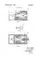
- FIG. 3is a partial cross-sectional view of the connector that houses the male contacts.
- FIG. 4illustrates a cross-sectional view of the connector of FIG. 3 in mated relationship with the circuit board.
- FIG. 5illustrates a preferred embodiment of an electrical contact.
- FIG. 6illustrates a connector board and connector that embodies the principles of this invention.
- FIG. 1illustrates the basic components of this new type of connector.
- Two axially aligned male members 10each of which has an angled surface portion 11 are arranged in spaced relationship so that a circuit board 5 may pass therebetween.
- the circuit board 5includes a hole that has an eyelet I mounted therein and a conducting path 3 that is in electrical circuit relationship with the eyelet l.
- the eyelet lis made of electrically conducting material and is pressed or soldered into place.
- the eyelet 1has been riveted into place and, therefore, includes a lip at both ends.
- a conduit without a lipcould be pressure fitted or soldered into position.
- a plated through-holemay also serve the purposes of this invention.
- FIG. 2illustrates the mated relationship between the elongated members 10 and the eyelet 1.
- An axial force applied to the elongated members 10 in the direction of the circuit board 5forces the members 10 to contact each other at end surfaces 1 I. Since the angled surfaces 11 are generally in face-to-face parallel relationship, they force the elongated members 10 out of alignment with each other and into the wall of the eyelet 1. Therefore, increasing the axial force on the elongated members 10 increases the force on the inner wall of the eyelet l by the elongated members 10.
- FIG. 3illustrates a preferred type connector 30 which contains male electrical contacts 10 that accomplish the objects of this invention.
- an outer casing 8which contains the inner housing 12, the male contacts 10, the roller bearings 14 and confining members 16. Confining members 16 extend through the outer casing 8 thereby supporting the housing 12 away from one wall of the inner casing 8 and permitting the housing 12 to slide back and forth within the casing 8.
- the housing 12includes an opening 13 for receiving a circuit board. Adjacent to and in line with the opening 13 is a blocking member 17 which is mounted on the wall of the housing 12. The blocking member 17 prevents a circuit board (not shown), which enters opening 13, from entering any further into the housing 12.
- the elongated male membersare connected together in a Y-shape wherein one end of the male members is for receiving an electrical conductor to be placed in electrical circuit relationship with a predetermined terminal on a circuit board.
- the other end of the Ywhich comprises the two male contact members 10, is resilient so that the male contacts may move towards and away from each other.
- the roller 14 and member 16are confined to the space between the elongated members 10 and the inner walls of the housing 12.
- FIG. 4illustrates a cross-sectional view of the connector shown in FIG. 3 in mated relationship with a circuit board 5.
- This viewillustrates how the housing 12 has been moved further into the casing 8 by the action of the circuit board 5 entering the opening 13 and pressing against member 17.
- the wiping action of the male contacts 10 against the inner wall of the eyelet lcleans the contact surfaces of oxides and helps to assure a low resistance drop between the two surfaces over the life of the connector.
- the connector assemblymay be modified to include a detent or catch that will hold the housing 12 in the position into which it has been moved by the insertion of the circuit board 5 into the housing 12.
- FIG. 5illustrates a preferred embodiment of a pair of male electrical contacts.
- a Y-shaped piece of metal having movable arms 9 and a base portion 15comprises the male contact.
- the base portion 15 of the Yincludes an opening 19 for receiving an electrical conductor.
- the other end of the base portionis hollowed out to give additional resilience to the arms 9.
- the ends of each arm 9are bent towards each other so that each arm 9 includes an axially elongated portion 10 in axial alignment with the axially elongated portion of another arm.
- elongated portion 10terminates in an angled surface which makes an angle of about 30 from the end of the elongated portion 10. It is readily apparent that the application of a force against the arms 9 in the direction towards the other arm will result in the contacting of surfaces 11 against each other. When the force against the arms 9 is removed, the arms 9 will return to their original position.
- FIG. 6illustrates a separable connector which includes a circuit board 5 and a socket 30 that receives the circuit board 5, the socket being the terminal portion of a plurality of electrical wires (not shown).
- a connector assemblycomprising:
- a first elongated memberhaving an end portion with an angled surface
- a second elongated and electrically conductive memberintegrally connected to and axially aligned with said first member and having an end portion with an angled surface in generally face-toface relationship with the angled surface of said first member;
- a housinghaving a first face, a second face opposite said first face, a passage extending therethrough from said first face to said second face, and a conduit comprised of an electrically conducting material mounted in said passage, said conduit having a first opening at one end for receiving said first member and a second opening at the other end for receiving said second elongated member, said conduit sized so that when the angled surface portion of said first member is inserted into said conduit first opening and the angled surface portion of said second member is inserted into said conduit second opening said angled surfaces, opposing each other, contact each other and force at least said second member into pressurized contact with the wall of said conduit whereby increasing the axial force on said elongated members increases the force on said conduit inner wall by said second elongated member.
- An electrical connector assemblycomprising:
- a receptacle for receiving a plugsaid receptacle including:
- a first elongated electrical conductorhaving an end portion with an angled surface
- a second elongated electrical conductorhaving an end portion with an opposing angled surface
- a plugwhich includes:
- an electrical conducting tubehaving an opening at one end for receiving said first elongated conductor, an opening at the other end for receiving said second elongated conductor, and an axial passage therethrough that has a cross-sectional area larger than the cross-sectional are of one of said elongated conductors but smaller than the total cross-sectional area of both of said elongated conductors, so that when said plug is in mated relationship with said receptacle, a portion of each of said elongated conductors is forced into pressurized contact with the wall of said housing passage.
- An electrical receptacle for connecting a first electrical conductor to a second electrical conductorwhich comprises:
- a housinghaving an opening therein for receiving said first electrical conductor
- said electrical contactincluding:
- a first elongated electrically conducting memberhaving an end portion with an angled surface
- a second elongated electrically conducting memberaxially aligned with said first elongated member and having an end portion with an angled surface in planar relationship with the angled surface of said first member, said first and second elongated members disposed adjacent said opening inside said housing;
- said meansincluding means for receiving said second electrical conductor, said first electrical conductor that is inserted into said housing opening including an opening that receives said first and second elongated members when said first conductor is inserted in said housing opening;
- a circuit board connector assemblywhich comprises:
- circuit boardhaving a plurality of holes arranged in spaced relationship along an end portion of said board, said circuit board having electrical conductors thereon that terminate at one or more of said holes;
- each of said conduitshaving an inner cross-sectional passage of area A adapted to receive a pair of elongated conductors, said conduits in electrical circuit relationship with the electrical conductor mounted on said circuit board that terminates at said hole; and a male connector which includes:
- each pair of said elongated conductorsbeing part of a single unitary structure adapted to mate with a corresponding conduit passage in said circuit board, and each of said conductors having a tapered end portion and a non-tapered portion,
- the cross-sectional area of said non-tapered portionbeing less than the cross-sectional area A of one of said conduits but the total cross-sectional area of two of said conductors at said non-tapered portion being greater than the cross-sectional area A of one of said conduits so that when said elongated conductors are in mated relationship with said conduits said elongated conductor pairs are in pressure contact with the inner walls of said conduits.
- a separable electrical connector for circuit boardscomprising in combination:
- circuit boardhaving a plurality of holes spaced adjacent to at least one edge of said board
- an electrical conducting conduitlocated in at least gled surface with at least one of said members one of said holes, said conduit in electrical circuit adapted to move in a direction towards the other relationship with said conductive surface terminatmember so h h angled Surfaces f i male mg at S'ald hqle;and members contact each other forcing said male 3 socket mcludmg' members out of alignment, whereby when said cira pair of axially aligned elongated male members adapted to pass into one of said conduits in said circuit board, said pair of male members being part of a single unitary structure with each of said male members terminating in an angled surface in i0 generally fa'ce-to-face relationship to the other ancuit board and said socket are in mated relationship both of said male members are in pressure contact with the walls of said conduit in said circuit board.
Landscapes
- Engineering & Computer Science (AREA)
- Manufacturing & Machinery (AREA)
- Microelectronics & Electronic Packaging (AREA)
- Coupling Device And Connection With Printed Circuit (AREA)
- Mounting Of Printed Circuit Boards And The Like (AREA)
Abstract
Description
Claims (8)
Applications Claiming Priority (2)
| Application Number | Priority Date | Filing Date | Title |
|---|---|---|---|
| US12680171A | 1971-03-22 | 1971-03-22 | |
| US12680371A | 1971-03-22 | 1971-03-22 |
Publications (1)
| Publication Number | Publication Date |
|---|---|
| US3731252Atrue US3731252A (en) | 1973-05-01 |
Family
ID=26825037
Family Applications (2)
| Application Number | Title | Priority Date | Filing Date |
|---|---|---|---|
| US00126803AExpired - LifetimeUS3725853A (en) | 1971-03-22 | 1971-03-22 | Electrical contact |
| US00126801AExpired - LifetimeUS3731252A (en) | 1971-03-22 | 1971-03-22 | Printed circuit board connector |
Family Applications Before (1)
| Application Number | Title | Priority Date | Filing Date |
|---|---|---|---|
| US00126803AExpired - LifetimeUS3725853A (en) | 1971-03-22 | 1971-03-22 | Electrical contact |
Country Status (7)
| Country | Link |
|---|---|
| US (2) | US3725853A (en) |
| JP (1) | JPS5411915B1 (en) |
| CA (2) | CA945647A (en) |
| DE (1) | DE2213989A1 (en) |
| FR (1) | FR2130534B1 (en) |
| GB (1) | GB1351896A (en) |
| IT (1) | IT950476B (en) |
Cited By (21)
| Publication number | Priority date | Publication date | Assignee | Title |
|---|---|---|---|---|
| US3930707A (en)* | 1974-06-10 | 1976-01-06 | A P Products Incorporated | Interface connector |
| DE2538396A1 (en)* | 1974-08-29 | 1976-03-11 | Amp Inc | UNIT CONSISTING OF AN EDGE CONNECTOR FOR PRINTED CIRCUIT PANELS AND A LOCKING CLIP |
| US4069403A (en)* | 1976-09-13 | 1978-01-17 | The Singer Company | Switching apparatus for electrically contacting conductive terminals on a circuit-carrying board |
| US4373764A (en)* | 1980-03-28 | 1983-02-15 | Hasler Ag Bern | Electrical connector |
| US4487468A (en)* | 1982-12-27 | 1984-12-11 | Amp Incorporated | Card edge connector locking device |
| US5074797A (en)* | 1989-07-21 | 1991-12-24 | Thomas & Betts Corporation | Electrical Connector for Connecting Heat Seal Film to a Printed Wiring Board |
| US5259767A (en)* | 1992-07-10 | 1993-11-09 | Teledyne Kinetics | Connector for a plated or soldered hole |
| US5472349A (en)* | 1994-10-31 | 1995-12-05 | The Whitaker Corporation | Surface mountable board edge connector |
| US5484295A (en)* | 1994-04-01 | 1996-01-16 | Teledyne Electronic Technologies | Low profile compression electrical connector |
| EP0615310A3 (en)* | 1993-03-09 | 1996-02-21 | Siemens Ag | Press fit connection for components in holes of a printed circuit board. |
| US5800186A (en)* | 1997-03-13 | 1998-09-01 | Framatome Connectors Usa, Inc. | Printed circuit board assembly |
| US6618942B2 (en)* | 2001-10-04 | 2003-09-16 | International Business Machines Corporation | Method for insertion of inserting printed circuit card into socket connectors |
| US20050266728A1 (en)* | 2002-08-30 | 2005-12-01 | Fci Americas Technology, Inc. | Electrical connector with load bearing features |
| US20060073724A1 (en)* | 2002-08-30 | 2006-04-06 | Fci Americas Technology, Inc. | Connector receptacle having a short beam and long wipe dual beam contact |
| US20060085155A1 (en)* | 2001-05-24 | 2006-04-20 | Emilio Miguelanez | Methods and apparatus for local outlier detection |
| US20080307141A1 (en)* | 2007-06-08 | 2008-12-11 | George Buchert | Sliding card carrier |
| US7819708B2 (en) | 2005-11-21 | 2010-10-26 | Fci Americas Technology, Inc. | Receptacle contact for improved mating characteristics |
| US20100291790A1 (en)* | 2009-05-12 | 2010-11-18 | Fujitsu Component Limited | Flexible cable connecting structure and flexible cable connector |
| US20120156912A1 (en)* | 2010-12-20 | 2012-06-21 | Hon Hai Precision Industry Co., Ltd. | Card edge connector |
| CN103878522A (en)* | 2014-03-14 | 2014-06-25 | 罗后帅 | Full-automatic electric eye alignment machine |
| US10062990B1 (en)* | 2017-05-25 | 2018-08-28 | Valeo North America, Inc. | Connector with locking teeth |
Families Citing this family (9)
| Publication number | Priority date | Publication date | Assignee | Title |
|---|---|---|---|---|
| US3944313A (en)* | 1974-07-31 | 1976-03-16 | The Bendix Corporation | Bifurcated electrical contact |
| BE847127A (en)* | 1975-10-17 | 1977-01-31 | ELECTRICAL CONTROL CONNECTION DEVICE, | |
| DE8318896U1 (en)* | 1983-06-30 | 1983-12-08 | Preh, Elektrofeinmechanische Werke, Jakob Preh, Nachf. Gmbh & Co, 8740 Bad Neustadt | Multiple connector |
| US4700997A (en)* | 1986-11-14 | 1987-10-20 | Minnesota Mining And Manufacturing Company | Electrical connector |
| US4761143A (en)* | 1987-01-20 | 1988-08-02 | Owens Rick L | Electrode clip |
| US4897045A (en)* | 1987-10-13 | 1990-01-30 | Arthur Dyck | Wire-seizing connector for co-axial cable |
| US4842558A (en)* | 1988-10-14 | 1989-06-27 | Minnesota Mining And Manufacturing Company | Electrical connector |
| US7377809B2 (en)* | 2006-04-14 | 2008-05-27 | Extreme Broadband Engineering, Llc | Coaxial connector with maximized surface contact and method |
| US8585438B2 (en) | 2012-03-21 | 2013-11-19 | Antronix, Inc. | Ground maintaining auto seizing coaxial cable connector |
Citations (11)
| Publication number | Priority date | Publication date | Assignee | Title |
|---|---|---|---|---|
| US2702895A (en)* | 1951-01-04 | 1955-02-22 | Pavlinetz George | Terminal connector |
| FR72723E (en)* | 1957-06-01 | 1960-07-22 | Electrical terminal couplers | |
| GB863049A (en)* | 1958-08-08 | 1961-03-15 | Standard Telephones Cables Ltd | Improvements in or relating to electrical connectors |
| US3140907A (en)* | 1960-06-03 | 1964-07-14 | Int Standard Electric Corp | Electrical spring contact sockets |
| US3149896A (en)* | 1960-11-04 | 1964-09-22 | Bendix Corp | Electrical connector |
| US3188598A (en)* | 1962-06-20 | 1965-06-08 | Bell Telephone Labor Inc | Printed circuit board connector |
| US3441898A (en)* | 1967-04-06 | 1969-04-29 | Nils Ingvar Nodfelt | Connection device for electric cables |
| US3538486A (en)* | 1967-05-25 | 1970-11-03 | Amp Inc | Connector device with clamping contact means |
| US3569789A (en)* | 1968-05-30 | 1971-03-09 | Siemens Ag | Plug-in type connector having short signal path |
| US3594699A (en)* | 1969-12-15 | 1971-07-20 | Sylvania Electric Prod | Articulated printed circuit edge connector |
| US3620490A (en)* | 1970-10-09 | 1971-11-16 | Francis Eugene Roberts | Cable hanger |
Family Cites Families (1)
| Publication number | Priority date | Publication date | Assignee | Title |
|---|---|---|---|---|
| FR1528076A (en)* | 1967-04-28 | 1968-06-07 | Radiotechnique Coprim Rtc | Terminal for electronic device comprising a flat support |
- 1971
- 1971-03-22USUS00126803Apatent/US3725853A/ennot_activeExpired - Lifetime
- 1971-03-22USUS00126801Apatent/US3731252A/ennot_activeExpired - Lifetime
- 1972
- 1972-02-28CACA135,715Apatent/CA945647A/ennot_activeExpired
- 1972-02-28CACA135,714Apatent/CA940212A/ennot_activeExpired
- 1972-03-22GBGB1343772Apatent/GB1351896A/ennot_activeExpired
- 1972-03-22FRFR7209979Apatent/FR2130534B1/frnot_activeExpired
- 1972-03-22JPJP2888372Apatent/JPS5411915B1/jaactivePending
- 1972-03-22ITIT22230/72Apatent/IT950476B/enactive
- 1972-03-22DEDE19722213989patent/DE2213989A1/enactivePending
Patent Citations (11)
| Publication number | Priority date | Publication date | Assignee | Title |
|---|---|---|---|---|
| US2702895A (en)* | 1951-01-04 | 1955-02-22 | Pavlinetz George | Terminal connector |
| FR72723E (en)* | 1957-06-01 | 1960-07-22 | Electrical terminal couplers | |
| GB863049A (en)* | 1958-08-08 | 1961-03-15 | Standard Telephones Cables Ltd | Improvements in or relating to electrical connectors |
| US3140907A (en)* | 1960-06-03 | 1964-07-14 | Int Standard Electric Corp | Electrical spring contact sockets |
| US3149896A (en)* | 1960-11-04 | 1964-09-22 | Bendix Corp | Electrical connector |
| US3188598A (en)* | 1962-06-20 | 1965-06-08 | Bell Telephone Labor Inc | Printed circuit board connector |
| US3441898A (en)* | 1967-04-06 | 1969-04-29 | Nils Ingvar Nodfelt | Connection device for electric cables |
| US3538486A (en)* | 1967-05-25 | 1970-11-03 | Amp Inc | Connector device with clamping contact means |
| US3569789A (en)* | 1968-05-30 | 1971-03-09 | Siemens Ag | Plug-in type connector having short signal path |
| US3594699A (en)* | 1969-12-15 | 1971-07-20 | Sylvania Electric Prod | Articulated printed circuit edge connector |
| US3620490A (en)* | 1970-10-09 | 1971-11-16 | Francis Eugene Roberts | Cable hanger |
Cited By (29)
| Publication number | Priority date | Publication date | Assignee | Title |
|---|---|---|---|---|
| US3930707A (en)* | 1974-06-10 | 1976-01-06 | A P Products Incorporated | Interface connector |
| DE2538396A1 (en)* | 1974-08-29 | 1976-03-11 | Amp Inc | UNIT CONSISTING OF AN EDGE CONNECTOR FOR PRINTED CIRCUIT PANELS AND A LOCKING CLIP |
| US3970353A (en)* | 1974-08-29 | 1976-07-20 | Amp Incorporated | Locking clip |
| US4069403A (en)* | 1976-09-13 | 1978-01-17 | The Singer Company | Switching apparatus for electrically contacting conductive terminals on a circuit-carrying board |
| US4373764A (en)* | 1980-03-28 | 1983-02-15 | Hasler Ag Bern | Electrical connector |
| USRE32559E (en)* | 1982-12-27 | 1987-12-15 | Amp Incorporated | Card edge connector locking device |
| US4487468A (en)* | 1982-12-27 | 1984-12-11 | Amp Incorporated | Card edge connector locking device |
| US5074797A (en)* | 1989-07-21 | 1991-12-24 | Thomas & Betts Corporation | Electrical Connector for Connecting Heat Seal Film to a Printed Wiring Board |
| US5259767A (en)* | 1992-07-10 | 1993-11-09 | Teledyne Kinetics | Connector for a plated or soldered hole |
| EP0615310A3 (en)* | 1993-03-09 | 1996-02-21 | Siemens Ag | Press fit connection for components in holes of a printed circuit board. |
| US5484295A (en)* | 1994-04-01 | 1996-01-16 | Teledyne Electronic Technologies | Low profile compression electrical connector |
| US5472349A (en)* | 1994-10-31 | 1995-12-05 | The Whitaker Corporation | Surface mountable board edge connector |
| US5800186A (en)* | 1997-03-13 | 1998-09-01 | Framatome Connectors Usa, Inc. | Printed circuit board assembly |
| US20060085155A1 (en)* | 2001-05-24 | 2006-04-20 | Emilio Miguelanez | Methods and apparatus for local outlier detection |
| US6618942B2 (en)* | 2001-10-04 | 2003-09-16 | International Business Machines Corporation | Method for insertion of inserting printed circuit card into socket connectors |
| US20050266728A1 (en)* | 2002-08-30 | 2005-12-01 | Fci Americas Technology, Inc. | Electrical connector with load bearing features |
| US20060073724A1 (en)* | 2002-08-30 | 2006-04-06 | Fci Americas Technology, Inc. | Connector receptacle having a short beam and long wipe dual beam contact |
| US7182616B2 (en)* | 2002-08-30 | 2007-02-27 | Fci Americas Technology, Inc. | Connector receptacle having a short beam and long wipe dual beam contact |
| US7270573B2 (en) | 2002-08-30 | 2007-09-18 | Fci Americas Technology, Inc. | Electrical connector with load bearing features |
| US7819708B2 (en) | 2005-11-21 | 2010-10-26 | Fci Americas Technology, Inc. | Receptacle contact for improved mating characteristics |
| US20080307141A1 (en)* | 2007-06-08 | 2008-12-11 | George Buchert | Sliding card carrier |
| US7830670B2 (en) | 2007-06-08 | 2010-11-09 | Mission Technology Group, Inc. | Sliding card carrier |
| US20100291790A1 (en)* | 2009-05-12 | 2010-11-18 | Fujitsu Component Limited | Flexible cable connecting structure and flexible cable connector |
| US8292648B2 (en)* | 2009-05-12 | 2012-10-23 | Fujitsu Component Limited | Flexible cable connecting structure and flexible cable connector |
| US20120156912A1 (en)* | 2010-12-20 | 2012-06-21 | Hon Hai Precision Industry Co., Ltd. | Card edge connector |
| US8535077B2 (en)* | 2010-12-20 | 2013-09-17 | Hon Hai Precision Industry Co., Ltd. | Card edge connector |
| CN103878522A (en)* | 2014-03-14 | 2014-06-25 | 罗后帅 | Full-automatic electric eye alignment machine |
| CN103878522B (en)* | 2014-03-14 | 2015-09-16 | 深圳市鑫赛自动化设备有限公司 | A kind of full-automatic electric eye aligning machine |
| US10062990B1 (en)* | 2017-05-25 | 2018-08-28 | Valeo North America, Inc. | Connector with locking teeth |
Also Published As
| Publication number | Publication date |
|---|---|
| IT950476B (en) | 1973-06-20 |
| CA940212A (en) | 1974-01-15 |
| DE2213989A1 (en) | 1972-10-05 |
| GB1351896A (en) | 1974-05-01 |
| FR2130534B1 (en) | 1975-10-24 |
| JPS5411915B1 (en) | 1979-05-18 |
| FR2130534A1 (en) | 1972-11-03 |
| US3725853A (en) | 1973-04-03 |
| CA945647A (en) | 1974-04-16 |
Similar Documents
| Publication | Publication Date | Title |
|---|---|---|
| US3731252A (en) | Printed circuit board connector | |
| US3715706A (en) | Right angle electrical connector | |
| US2811700A (en) | Electrical connector for printed wiring board | |
| US4029375A (en) | Miniature electrical connector | |
| US4116516A (en) | Multiple layered connector | |
| US3710303A (en) | Edge connector | |
| US3479634A (en) | Printed circuit board connectors | |
| US3097032A (en) | Pin socket for miniature electrical components | |
| US5176528A (en) | Pin and socket electrical connnector assembly | |
| US3663925A (en) | Electrical connector | |
| US3514737A (en) | Printed circuit board socket connector | |
| US5595505A (en) | Electrical connector for conductive leads | |
| US2870424A (en) | Electrical socket for miniature components | |
| US3275765A (en) | Electrical connecting and switch device | |
| US3601774A (en) | Connector device having serially disposed pretensioned contacts | |
| GB1184755A (en) | Improvements in or relating to Connector Assemblies for Printed Circuits | |
| EP0961352A1 (en) | Multi-pin connector for flat cable | |
| US4606599A (en) | Low insertion force connector | |
| GB1012747A (en) | Printed circuit board connector | |
| US3422394A (en) | Electrical connector | |
| US3384864A (en) | Electrical connector assembly | |
| US3206717A (en) | Connector assembly | |
| US3871737A (en) | Socket contact with conductive elastomer contacting surface | |
| US4355856A (en) | Low insertion force connector using non-noble metal contact plating | |
| US5135412A (en) | Hold-down terminal |
Legal Events
| Date | Code | Title | Description |
|---|---|---|---|
| AS | Assignment | Owner name:CANADIAN IMPERIAL BANK OF COMMERCE, NEW YORK AGENC Free format text:SECURITY INTEREST;ASSIGNOR:AMPHENOL CORPORATION;REEL/FRAME:004879/0030 Effective date:19870515 Owner name:ALLIED CORPORATION, A CORP. OF NY Free format text:MERGER;ASSIGNOR:BENDIX CORPORATION, THE,;REEL/FRAME:004765/0709 Effective date:19850401 | |
| AS | Assignment | Owner name:AMPHENOL CORPORATION, A CORP. OF DE, ILLINOIS Free format text:ASSIGNMENT OF ASSIGNORS INTEREST;ASSIGNOR:ALLIED CORPORATION, A CORP. OF NY;REEL/FRAME:004844/0850 Effective date:19870602 Owner name:AMPHENOL CORPORATION, LISLE, ILLINOIS A CORP. OF D Free format text:ASSIGNMENT OF ASSIGNORS INTEREST.;ASSIGNOR:ALLIED CORPORATION, A CORP. OF NY;REEL/FRAME:004844/0850 Effective date:19870602 | |
| AS | Assignment | Owner name:AMPHENOL CORPORATION A CORP. OF DELAWARE Free format text:RELEASED BY SECURED PARTY;ASSIGNOR:CANADIAN IMPERIAL BANK OF COMMERCE;REEL/FRAME:006147/0887 Effective date:19911114 |