US3693613A - Surgical handpiece and flow control system for use therewith - Google Patents
Surgical handpiece and flow control system for use therewithDownload PDFInfo
- Publication number
- US3693613A US3693613AUS96473AUS3693613DAUS3693613AUS 3693613 AUS3693613 AUS 3693613AUS 96473 AUS96473 AUS 96473AUS 3693613D AUS3693613D AUS 3693613DAUS 3693613 AUS3693613 AUS 3693613A
- Authority
- US
- United States
- Prior art keywords
- flow
- source
- operative site
- negative pressure
- treatment fluid
- Prior art date
- Legal status (The legal status is an assumption and is not a legal conclusion. Google has not performed a legal analysis and makes no representation as to the accuracy of the status listed.)
- Expired - Lifetime
Links
- 239000012530fluidSubstances0.000claimsabstractdescription147
- 239000000725suspensionSubstances0.000claimsabstractdescription69
- 239000000463materialSubstances0.000claimsabstractdescription25
- 238000013022ventingMethods0.000claimsabstractdescription25
- 239000002826coolantSubstances0.000claimsdescription18
- 230000008878couplingEffects0.000claimsdescription15
- 238000010168coupling processMethods0.000claimsdescription15
- 238000005859coupling reactionMethods0.000claimsdescription15
- 238000001816coolingMethods0.000claims1
- 230000002262irrigationEffects0.000abstractdescription12
- 238000003973irrigationMethods0.000abstractdescription12
- 208000002177CataractDiseases0.000abstractdescription11
- 239000007864aqueous solutionSubstances0.000abstractdescription3
- 210000002159anterior chamberAnatomy0.000description11
- 210000004087corneaAnatomy0.000description4
- 230000000694effectsEffects0.000description4
- 230000009471actionEffects0.000description3
- 238000000034methodMethods0.000description3
- 239000002245particleSubstances0.000description3
- 230000037452primingEffects0.000description3
- 239000000243solutionSubstances0.000description3
- 239000002775capsuleSubstances0.000description2
- 238000010276constructionMethods0.000description2
- 238000006073displacement reactionMethods0.000description2
- 238000012423maintenanceMethods0.000description2
- 230000002572peristaltic effectEffects0.000description2
- 230000004044responseEffects0.000description2
- 210000001519tissueAnatomy0.000description2
- 230000007704transitionEffects0.000description2
- 241000950638Symphysodon discusSpecies0.000description1
- 241000893638TaractesSpecies0.000description1
- 230000008901benefitEffects0.000description1
- 230000008859changeEffects0.000description1
- 238000006243chemical reactionMethods0.000description1
- 238000004140cleaningMethods0.000description1
- 238000010586diagramMethods0.000description1
- 230000008030eliminationEffects0.000description1
- 238000003379elimination reactionMethods0.000description1
- 210000003038endotheliumAnatomy0.000description1
- 230000001788irregularEffects0.000description1
- HOQADATXFBOEGG-UHFFFAOYSA-NisofenphosChemical compoundCCOP(=S)(NC(C)C)OC1=CC=CC=C1C(=O)OC(C)CHOQADATXFBOEGG-UHFFFAOYSA-N0.000description1
- 239000007788liquidSubstances0.000description1
- 239000012528membraneSubstances0.000description1
- 230000035945sensitivityEffects0.000description1
- 230000001954sterilising effectEffects0.000description1
- 238000004659sterilization and disinfectionMethods0.000description1
- 230000001052transient effectEffects0.000description1
Images

Classifications
- A—HUMAN NECESSITIES
- A61—MEDICAL OR VETERINARY SCIENCE; HYGIENE
- A61F—FILTERS IMPLANTABLE INTO BLOOD VESSELS; PROSTHESES; DEVICES PROVIDING PATENCY TO, OR PREVENTING COLLAPSING OF, TUBULAR STRUCTURES OF THE BODY, e.g. STENTS; ORTHOPAEDIC, NURSING OR CONTRACEPTIVE DEVICES; FOMENTATION; TREATMENT OR PROTECTION OF EYES OR EARS; BANDAGES, DRESSINGS OR ABSORBENT PADS; FIRST-AID KITS
- A61F9/00—Methods or devices for treatment of the eyes; Devices for putting in contact-lenses; Devices to correct squinting; Apparatus to guide the blind; Protective devices for the eyes, carried on the body or in the hand
- A61F9/007—Methods or devices for eye surgery
- A61F9/00736—Instruments for removal of intra-ocular material or intra-ocular injection, e.g. cataract instruments
- A61F9/00745—Instruments for removal of intra-ocular material or intra-ocular injection, e.g. cataract instruments using mechanical vibrations, e.g. ultrasonic
- A—HUMAN NECESSITIES
- A61—MEDICAL OR VETERINARY SCIENCE; HYGIENE
- A61B—DIAGNOSIS; SURGERY; IDENTIFICATION
- A61B17/00—Surgical instruments, devices or methods
- A61B2017/00973—Surgical instruments, devices or methods pedal-operated
- A—HUMAN NECESSITIES
- A61—MEDICAL OR VETERINARY SCIENCE; HYGIENE
- A61B—DIAGNOSIS; SURGERY; IDENTIFICATION
- A61B17/00—Surgical instruments, devices or methods
- A61B17/32—Surgical cutting instruments
- A61B17/320068—Surgical cutting instruments using mechanical vibrations, e.g. ultrasonic
- A61B2017/320084—Irrigation sleeves
- A—HUMAN NECESSITIES
- A61—MEDICAL OR VETERINARY SCIENCE; HYGIENE
- A61M—DEVICES FOR INTRODUCING MEDIA INTO, OR ONTO, THE BODY; DEVICES FOR TRANSDUCING BODY MEDIA OR FOR TAKING MEDIA FROM THE BODY; DEVICES FOR PRODUCING OR ENDING SLEEP OR STUPOR
- A61M1/00—Suction or pumping devices for medical purposes; Devices for carrying-off, for treatment of, or for carrying-over, body-liquids; Drainage systems
- A61M1/84—Drainage tubes; Aspiration tips
- A61M1/85—Drainage tubes; Aspiration tips with gas or fluid supply means, e.g. for supplying rinsing fluids or anticoagulants
- Y—GENERAL TAGGING OF NEW TECHNOLOGICAL DEVELOPMENTS; GENERAL TAGGING OF CROSS-SECTIONAL TECHNOLOGIES SPANNING OVER SEVERAL SECTIONS OF THE IPC; TECHNICAL SUBJECTS COVERED BY FORMER USPC CROSS-REFERENCE ART COLLECTIONS [XRACs] AND DIGESTS
- Y10—TECHNICAL SUBJECTS COVERED BY FORMER USPC
- Y10T—TECHNICAL SUBJECTS COVERED BY FORMER US CLASSIFICATION
- Y10T137/00—Fluid handling
- Y10T137/2496—Self-proportioning or correlating systems
- Y10T137/2559—Self-controlled branched flow systems
- Y10T137/2574—Bypass or relief controlled by main line fluid condition
- Y10T137/2579—Flow rate responsive
Definitions
- the aspira- [58] Field of Search ..l28/24 A, 278, 303, 303.1; on subsystemcomprises a pump used to remove the 137/117i417/300 suspension and to overcome the friction and other losses throughout the entire fluid system, a flow trans- [56] Ree'ences cued ducer for measuring the rate of flow, and a vent valve UNITED STATES PATENTS to reduce the flow in the aspiration subsystem when necessary to assist in maintaining a relatively constant 2,355,945 10/1958 Gratlmllllel UX pressure within the operative site.
- Balamuth ..l28/24 A controlreceives signals from the flow transducer and 3,528,410 9/1970 Banko ..l28/24 A reacts t ertain changes in flow signals by sending a "OCH X signal to the venting va]ve 3,581,760 6/197] West ..l37/l 17 X 3,589,363 6/1971 Banko ..l28/24 A X Primary Examiner-Channing L.
- PMENTEDszrzs I972sum 1 or 2 l'lllllllllr El llllllllll f! '4 mm mm M O ll I INVENTOR.
- Charles Kelman 4 ATTORNY SURGICAL HANDPIECE AND FLOW CONTROL SYSTEM FOR USE THEREWITH BACKGROUND OF THE INVENTIONThe present invention relates to a flow control system to be used with surgical handpiece, the combination of which is primarily concerned with the removal of tissue from any enclosed or semi-enclosed operative site.
- This flow control systemis particularly of interest and value where it is important that the pressure in the operative site be maintained within relative ly narrow limits and particularly where the total volume of the operative site chamber is very small in relation to the rest of the fluid in the system.
- the present systemis of particular advantage when used with an ultrasonic handpiece for the removal of a cataract lens in the human eye.
- the usual procedure in e o o taract lens from a human eyeoften involves a 180 incision allow the surgeon to lift up the cornea and lift out the lens in toto.
- the flow control system of this inventionmakes it possible to remove a cataract lens from a human eye by making only a small incision in the eye and inserting the tip of the surgical handpiece therein so that the tip is within the anterior chamber (operative site) of the eye providing access to the lens.
- One type of handpiece(hereinafter to be referred to as the ultrasonic handpiece), includes a source of vibratory motion as well as a passage for treatment fluid to flow into the anterior chamber (operative site) and a passage for the fluid and unwanted material (hereinafter to be referred to as the suspension), to exit from the anterior chamber (operative site).
- the combined or separate action of the flowing fluid and/or the force of the vibratory motion of the handpiece when in contact with or adjacent to the lens of the eyewill cause the lens to break apart and be removed from the eye.
- A. Banko and C. KelmanSer. No.
- irrigation-aspiration handpieceAnother type of handpiece, (hereinafter to be referred to as the irrigation-aspiration handpiece), merely contains two passages for flow into and out of the operative site. lt is usually used during a type of cleaning up" procedure within the enclosed operative site, though may be used as an alternative to the ultrasonic handpiece where the unwanted material is particularly soft and does not require the use of ultrasonics to break it apart.
- the pressure of the' anterior chamberis maintained within a certain range of values, since otherwise various portions of the eye could be damaged.
- a collapse of the anterior chambercould result in either the iris, the endothelium layer of the cornea, or the posterior capsule, as well as other parts coming into contact with that portion of the handpiece within the eye which is connected to a source of fluid suction as well as a source of high frequency vibration, either of which could cause damage to one or more of the above-named parts of the eye.
- This problem of maintaining the proper pressureis a particularly difficult and sensitive one in the case of an operative site wherein the volume of said operative site considerably smaller than the volume of fluid which is necessary for the irrigating and aspirating subsystems connected to the handpiece for maintaining the necessary flow to and from the operative site.
- the volume of said operative siteconsiderably smaller than the volume of fluid which is necessary for the irrigating and aspirating subsystems connected to the handpiece for maintaining the necessary flow to and from the operative site.
- the lens or portions thereofare drawn towards the surgical handpiece tip within the operative site, there is a possibility of particles which are bigger than the exit passage from the operative site to occlude the fluid line in the tip portion of the handpiece leading to the aspiration subsystem.
- Another object of this inventionis to provide a flow control system for keeping the pressure within an enclosed or semi-enclosed operative site relatively constant while forcing a fluid through said chamber for the removal of unwanted material from said chamber.
- a further object of the inventionis to provide a flow control system for keeping the pressure in a small enclosed or semi-enclosed operative site relatively constant while forcing a fluid through said operative site and applying a high frequency mechanical vibratory force to a material within said chamber resulting in the breaking apart and removal of said material.
- a still further object of the inventionis to provide a flow control system which is sufficiently sensitive to certain changes in flow rates such that prior to any significant collapse of an enclosed site, an adjustment is made on the fluid system to avoid said collapse.
- FIG. Iis a cross-sectional view of an ultrasonic handpiece showing its basic internal construction
- FIG. 2is a cross-sectional view of an irrigationaspiration handpiece showing its basic internal construction
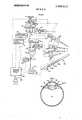
- FIG. 3is a pictorial representation of a human eye in enlarged form and illustrating the use of a surgical handpiece in cataract removal
- FIG. 4is a schematic diagram of the combination of the ultrasonic handpiece and the flow control system.
- the ultrcludes a proximal end 11 and a distal end 2 and hydraulically coupled to a power and coolant supply 15 (FIG. 4) at its proximal end 11 via a coolant fluid inlet tube 16 and a coolant fluid outlet tube 17 and a pair of electrical leads 18.
- the electrical leads 18are connected to coil 19 which is wound internally within the ultrasonic handpiece 10.
- a vibratory body 20containing a transducer element 21 at the proximal end 11 of said vibratory body 20.
- the transducer elementwhich may be either magnetostrictive or electrostrictive type converts the high frequency alternating current generated in the coil 19 into high frequency mechanical vibrations.
- the transducer element 21is energized by the coil 19 containing the high frequency electrical signal and the resulting mechanical vibrations are transmitted via a connecting body 22 to an operative tip 23 at the proximal end 12 of the handpiece 10.
- the high frequency electrical signalis provided by a circuit (not shown) in the power and coolant supply 15. There are many such circuits which are well known in the art and need not be further described here.
- a source of coolantis provided by the power and coolant supply 15, and it is carried to and from the handpiece by the coolant fluid inlet and outlet tubes 16 and 17.
- the other major elements of the handpiece 10which are coupled to the irrigation and aspiration subsystems of the flow control system, respectivel are a fluid inlet channel 24 and a fluihe fluid inl channeg: )onnects with an annular passage 26 wit in t e u trasonic handpiece 10 which surrounds the connecting body 22 and the operative tip 23 and terminates at the very distal end 12 of the handpiece 10.
- the fluid outlet channel 25connects with a bore 27 throuh the center of the con 22 LZ-of the d iece or more details on the operation of such an u r s o v trasomc handpiece reference made to the abovenamed copending patent application.
- the irrigation-aspiration handpiece 30, having proximal end 31 and a distal end 32has a fluid inlet channel 34 coupled to the irrigation subsystem of the flow control system.
- the fluid from the irrigation subsystemflows through an annular space 35 within the handpiece and exits at the distal end 32.
- the suspension from the operative siteflows through a center bore 36 and exits at the fluid outlet channel 37 at the proximal end 31 of the handpiece 30.
- the fluid outlet channel 37is coupled to the aspiration subsystem of the flow control system.
- FIG. 3A portion of a simplified cross-section of a human eye is shown to illustrate the manner in which the device is employed.
- the opaque or cataract lens which is to be removedis designated by the number 40, and is enclosed in a membrane including an outer portion 40a known as the anterior capsule.
- the irisis designated by the numeral 41 and the major gel-filled portion of the eye, or vitreous, is designated as 42.
- the cornea, the transparent outer surface of the eye,is shown as 43, and the portion of the eye generally called the anterior chamber is designated as 45.
- a small incision 46is made near the edge of the cornea 43 to prop'de access for the distal end 12 of the ultrasonic handpiece 10 or the distal end 32 of the irrigation-aspiration handpiece 30.
- the dotted linesrepresent electrical connections and the solid lines represent hydraulic connections.
- Those components of the flow control system which are hydraulically coupled to the fluid inlet channel 24 of the ultrasonic handpiece 10are part of the irrigation subsystem and those components which are hydraulically coupled to the fluid outlet channel 25 are part of the aspiration subsystem.
- the irrigation subsystemcomprises a treatment fluid supply 50 having a pressure I and a treatment fluid supply 55 having a pressure P,, with P being greater than P
- the treatment fluidis preferably a solution, which is compatible with the tissue being treated. For purposes of cataract removal, an artificial aqueous solution has been found to be satisfactory.
- the treatment fluid supplies 50 and 55are connected to the fluid inlet channel 24 of the ultrasonic handpiece 10 by hydraulic tubing 56.
- the function of the aspiration subsystemis to remove from the enclosed operative site (in the case of the eye it is the anterior chamber 45, see FIG. the excess treatment fluid and/or any other unwanted material which the surgeon may want to signal removed.
- the fluid and other unwanted material being removed from the enclosed operative siteshall hereinafter be referred to as the suspension. All the components of the aspiration subsystem are interconnected and connected to the fluid outlet channel 25 of the ultrasonic handpiece 10 by hydraulic tubing 58, hereinafter to be referred to as the main suction line.
- the aspiration subsystemincludes a flow transducer 60, which is the first major component downstream from the handpiece along the main suction line 58.
- the flow transducer 60does not impede the flow of the suspension, but it is designed to sense the flow rate and produce a corresponding electrical signal which is transmitted to the electronic flow control 70, which will be discussed in more detail later.
- the flow trans ducer 60which is a commercially available product, is an electromagnetic device which produces an electrical signal proportional to the flow velocity of the suspension.
- the flow transducer 60is energized by the master control panel 80.
- the next major component in the aspiration subsystem downstream from the flow transducer 60 and along the main suction line 58is the by-pass valve 90. Also connected to the by-pass valve via a tube 99 is a by-pass reservoir 100.
- the by-pass valve 90is a double action solenoid such that in one position, to be referred to as its aspiration position, the suspension is allowed to flow unimpeded through the main suction line 58 and there is no flow in tube 99. in the other position of the solenoid, to be referred to as its by-pass position, there is no flow of the suspension while the solution from the by-pass reservoir 100 is allowed to flow.
- the pump 110is a constant displacement, variable speed, peristaltic pump.
- the peristaltic featureis to avoid any contact of the pump with the suspension hence minimizing maintenance problems of the pump 110, and the tubing can be easily removed from the pump for the purposes of sterilization.
- the constant displacement featureis necessary in order to insure accurate sensing of flow by the flow transducer 60, especially due to the exceedingly small fluid volume of the anterior chamber 45 of the eye relative to the fluidic volume of the remaining hydraulic components of the system.
- Another component of the aspiration subsystemis the by-pass reservoir 100, coupled to the main suction line 58 via the by-pass valve 90.
- the solenoid of the by-pass valve 90switches to its by-pass position, the flow from the flow transducer 60 ceases, hence the aspiration of the anterior chamber 45 of the eye ceases, and instead there is a flow from the by-pass reservoir 100.
- the by-pass reservoir 100is used to insure that fluid fills all portions of the main suction line 58 at all times, so that the hydraulic response time of the system is kept to a minimum. Thus, even though suction at the handpiece 10 may not be desired, from time to time, the continuously running pump 110 is always ready to apply the required suction, wherever necessary.
- vent valve 120Another component of the aspiration subsystem is the vent valve 120 which is intermediate of the by-pass valve 90 and the pump 110.
- the vent valve 120is a spring loaded, electrically operated solenoid which is normally in a shut position.
- An electrical signal from the electronic flow control 70causes the vent valve 120 to open and close to complete a cycle. What determines the existence of such a signal shall be discussed in more detail later.
- the function of the vent valve 120is to provide for a pressure equalization between at mospheric pressure and the hydraulic pressure in the main suction line 58, hereinafter to be referred to as venting, hence negating pressure buildup in the aspiration subsystem upon removal of the occlusion.
- the master control panelselectively enables the vent valve 120. This allows the vent valve 120 to become inoperative so that the system can be started prior to the commencement of an operation.
- the electronic flow control 70has a control for adjusting the amount of time the vent valve 120 remains open.
- a suitable footswitch 130having a foot-actuated control am 135 with a conductive segment 136, is uses, having an off position, three stable on positions and a fourth position to be called the transition position or position T.
- Position Tresults only when the control arm 135 moves between two of its stable on" positions.
- footswitch position 1(hereinafter the irrigation position), since the conductive segment [36b of the control arm bridges the pair of spaced contacts 137, the treatment fluid supply 50 is actuated, such that the treatment fluid at a pressure P, flow to the fluid inlet channel 24.
- the solenoid of the by-pass valve 90remains in its by-pass position.
- footswitch position 2(hereinafter the irrigation and aspiration position), since the conductive segment l36b of the control arm 135 bridges the pair of spaced contacts 138, the treatment fluid supply 55 is actuated such that the treatment fluid at a pressure P, flows to the fluid inlet channel 24. in addition, since the conductive segment 1360 of the control arm 135 bridges the pair of spaced contacts 139, the by-pass valve 90 changes to its aspiration position.
- footswitch position 3(hereinafter the ultrasonic position), since the conductive segments l36b and 1360 bridge the pair of spaced contacts 141 and 142, it can be seen that the irrigation and aspiration subsystems remain in the same state as when the control arm 135 was in footswitch position 2.
- the conductive segment 136abridges the pair of spaced contacts 143, the circuit (not shown) of the power and coolant supply 15 is coupled to the ultrasonic handpiece l0, assuming the power and coolant supply 15 has already been energized by the master control panel 80. This results in high frequency vibrations of the operative tip 23 of the vibratory body at the proximal end 12 of handpiece l0.
- a pressurized coolantis caused to flow to the handpiece l0 and back to the power and coolant supply 15 via the coolant inlet an outlet tubes 16 and 17.
- All the other controls of the power and coolant supply 15are on the master control panel 80 including the on-off switch, the power level control of the circuit and the pressurizing of the coolant supply.
- Position T(the transition position) of the footswitch 130, occurs whenever the footswitch control arm 135 moves from position 1 to position 2 or vice versa.
- the conductive segment l36bbridges the pair of spaced contacts 144 which causes actuation of the electronic flow control 70 such that an electrical signal is sent to the vent valve 120 causing a venting of the main suction line 58, hence an equalization of the pressure in the entire aspiration subsystem.
- the electronic flow control 70which is energized by the master control panel 80, continually receives signals from the flow transducer 60 concerning the flow rate of the suspension and contains circuitry to differentiate these signals such that an electrical signal results whenever certain changes in the flow rate signals occur.
- the circuitryis designed so that whenever the flow rate falls below a first predetermined value and subsequently increases above a second predetermined value, a pulse is generated and sent to the vent valve 120. This results in the venting of the main suction line 58 causing the momentary elimination of the negative pressure at the bore 28 of the operative tip 23 and substantially reducing the flow of the suspension through the main suction line 58.
- the circuitry of the electronic flow control 70is designed so as to account for all of the fluidic parameters of the entire system.
- circuitry of the electronic flow control 70is designed so that whenever certain irregular conditions are sensed, such as the passage of air bubbles or lens particles through the flow transducer 60 or an impact against or constriction of one of the hydraulic tubes in the aspiration subsystem, the electronic flow control 70 will send an electrical signal to the vent valve 120.
- FIG. 4illustrates the use of the flow control system with the ultrasonic handpiece 10, it would be equally applicable with the irrigation-aspiration handpiece 30 except that footswitch position 3 would be inapplicable.
- PSince P, is used when the footswitch is in position 1 and there is no aspiration, it must be set at a value such that it will mantain the enclosed operative site at a relatively constant volume taking into account the pressure drops throughout the irrigation subsystem and the fluid and/or suspension which may flow from the enclosed operative site through the incision leakage around the proximal end of the handpiece.
- Pmust be at a value higher than P, since it will be used when the footswitch is in position 2 when there is aspiration due to the operation of the pump.
- the power leveldetermines the amplitude of that portion of the operative tip 23 which comes into contact with the cataract lens. Usually the minimum possible power level to accomplish the task is chosen.
- the electronic flow controlrequires certain internal balances of its electrical components to take into account the ambient factors of the operating room and needs to be energized prior to the commencement of an operation to stabilize it as to temperature, transient signals, etc. Therefore, after the priming of the entire irrigation and aspiration subsystems has been completed, the flow transducer 60 and the electronic flow control 70 are energized. Then while the entire system is operating at its maximum desired flow, as detennined by the various settings discussed above, the electronic flow control 70 is programmed to read such a flow as the maximum flow rate. Then an artificial occlusion is placed along the aspiration subsystem as close to the distal end 12 of the handpiece 10 as possible. The electronic flow control 70 is then programmed to sense this as the minimum flow rate.
- the main and most serious operating problem which the surgeon must contend withis when a particle occludes the tip 23 such that the suspension is unable to leave the enclosed operative site. Since the pump ll0 continues to operate, the vacuum in the main suction line 58 will tend to increase. The surgeon will become aware of such a condition almost instantaneously and will handle the handpiece and/or ultrasonic controls in such a manner as to break apart the occlusion. At the moment the occlusion clears the tip there would be a tendency for the fluid and/or suspension within the enclosed operative site to rush into the main suction line 58 to fill the vacuum created therein.
- any increased flow at the handpiece tip 23will be immediately sensed at the flow transducer 60, since the average time for an occlusion is very small and there is a column of liquid between the handpiece tip 23 and the flow transducer 60.
- the flow transducerwhich is continually sensing the flow, will send a signal to the electronic flow control 70 proportional to he higher rate for flow. Since the electronic flow control 70 has been electronically programmed to react to certain changes in'the flow signals, an output signal will be sent to the vent valve 120 to vent the main suction line 58 to atmosphere and reduce the vacuum in said line. Depending upon whether the condition is corrected after one venting, the signals from the flow transducer 60 may cause the electronic flow control 70 to send another output signal to the vent valve 120. This could be repeated several times until there is an equilibrium in the flow.
- Flow control system for removing a suspension of unwanted material in a treatment fluid from an enclosed operative sitecomprising,
- a source of treatment fluid at a certain pressure for causing said fluid to flow into the enclosed operative siteincluding hydraulic tubing for connecting said treatment fluid source to the enclosed operative site,
- a source of negative pressure for withdrawing the suspension from the enclosed operative siteincluding hydraulic tubing for connecting said negative pressure source to the enclosed operative site,
- a flow transducerintermediate of and interconnected by the hydraulic tubing between the nega tive pressure source and the enclosed operative site, for sensing the flow of suspension and for generating an electrical signal proportional to said flow
- vent valvecoupled to the hydraulic tubing between said flow transducer and said negative pressure source for venting the flow of the suspension to atmospheric pressure
- a flow control system in accordance with claim Ifurther involving a bypass reservoir and a solenoid operated valve located intermediate of and interconnected by the hydraulic tubing between the flow transducer and the negative pressure source, the solenoid operated valve having a first position wherein the suspension only flows from the flow transducer to the negative pressure source, and having a second position wherein fluid only flows from the bypass reservoir to the negative pressure source.
- said flow control systemfurther including switch means having at least two positions, said first switch position coupling only the source of treatment fluid having the lower pressure to the enclosed operative site, said second switch position coupling the source of treatment fluid having the higher pressure and the negative pressure source to the enclosed operative site, with the vent valve receiving an electrical signal to vent the hydraulic tubing between the flow transducer and the negative pressure source whenever the switch means moves between these two positions.
- Flow control system for removing a suspension of unwanted material in a treatment fluid from a small enclosed operative sitecomprising,
- a first source of treatment fluid at a certain pressure for causing said fluid to flow into the enclosed operative siteincluding hydraulic tubing for connecting said first treatment fluid source to the enclosed operative site
- a second source of treatment fluid at a pressure higher than the first source for causing said fluid to flow into the enclosed operative siteincluding hydraulic tubing for connecting said second treatment fluid source to the enclosed operative site
- a source of negative pressure for withdrawing the suspension from the enclosed operative siteincluding hydraulic tubing for connecting said negative pressure source to the enclosed operative site,
- a flow transducerintermediate of and interconnected by the hydraulic tubing between the negative pressure source and the enclosed operative site, for sensing'the flow of the suspension and for generating an electrical signal proportional to said flow
- vent valvecoupled to the hydraulic tubing between said flow transducer and said negative pressure source for venting the flow of the suspension to atmospheric pressure
- electronic flow control meanselectrically interconnected to said flow transducer and said vent valve for sensing certain changes in flow rates due to the signal received from said flow transducer and, at certain predetermined value, for sending an electrical signal to the vent valve for venting the hydraulic tubing through which said suspension flows, and
- a switch meanshaving at least two positions, said first switch position coupling only the first source of treatment fluid to the enclosed operative site, said second switch position coupling the second source of treatment fluid and the negative pressure source to the enclosed operative site, with the vent valve receiving an electrical signal to vent the hydraulic position coupling only the first source of treatment fluid to the enclosed operative site, said second switch position coupling the second source of treatment fluid and the negative pressure source to the enclosed operative site, with the vent valve receiving an electrical signal to vent the hydraulic tubing between the flow transducer and the negatubing between the flow transducer and the negative pressure source whenever the switch means tive pressure source whenever the switch means moves between these two positions. moves between these two positions. 8.
- a flow control system in accordance with claim 5the flow control system further includes further including further including a bypass reservoir, and
- a solenoid operated valvelocated intermediate of a solenoid operated valve located intermediate of and interconnected by the the hydraulic tubing and interconnected by the hydraulic tubing between the flow transducer and the negative presbetween the flow transducer and the negative pressure source, having a first position wherein the sure source, having a first position wherein the suspension only flows from the flow transducer to suspension only flows from the flow transducer to the negative pressure source, and having a second the negative pressure source, and having a second position wherein the fluid only flows from the position wherein fluid only flows from the bypass bypass reservoir to the negative pressure source. reservoir to the negative pressure source.
- the flow control systemcomprises frequency electrical energy, for converting said a first source of treatment fluid at a certain pressure l t i al energy t high frequency mechanical for causing said fluid to flow into the enclosed vibrations, and coupled to a source of coolant for operative site, including hydraulic tubing for concooling a portion of said vibratory body, and necting said first treatment fluid source to the en
- the flow control systemcomprises, closed operative site, a first source of treatment fluid at a certain pressure second source of treatment fluid at a pressure for causing said fluid to flow into the enclosed higher than the first source for causing said fluid to operative site, including hydraulic tubing for conflow into the enclosed operative site, including necting said first treatment fluid source to the enhydrau
- a switch meanshaving three positions, said first sure source to the enclosed operative site and energizing the high frequency vibratory body; with the vent valve receiving an electrical signal to vent the hydraulic tubing between the flow transducer and the negative pressure source whenever the switch means moves between the first and second positions.
Landscapes
- Health & Medical Sciences (AREA)
- Ophthalmology & Optometry (AREA)
- Heart & Thoracic Surgery (AREA)
- Surgery (AREA)
- Engineering & Computer Science (AREA)
- Biomedical Technology (AREA)
- Nuclear Medicine, Radiotherapy & Molecular Imaging (AREA)
- Vascular Medicine (AREA)
- Life Sciences & Earth Sciences (AREA)
- Animal Behavior & Ethology (AREA)
- General Health & Medical Sciences (AREA)
- Public Health (AREA)
- Veterinary Medicine (AREA)
- Surgical Instruments (AREA)
Abstract
Description
Claims (9)
Applications Claiming Priority (1)
| Application Number | Priority Date | Filing Date | Title |
|---|---|---|---|
| US9647370A | 1970-12-09 | 1970-12-09 |
Publications (1)
| Publication Number | Publication Date |
|---|---|
| US3693613Atrue US3693613A (en) | 1972-09-26 |
Family
ID=22257489
Family Applications (1)
| Application Number | Title | Priority Date | Filing Date |
|---|---|---|---|
| US96473AExpired - LifetimeUS3693613A (en) | 1970-12-09 | 1970-12-09 | Surgical handpiece and flow control system for use therewith |
Country Status (1)
| Country | Link |
|---|---|
| US (1) | US3693613A (en) |
Cited By (254)
| Publication number | Priority date | Publication date | Assignee | Title |
|---|---|---|---|---|
| US3736938A (en)* | 1971-11-15 | 1973-06-05 | Nasa | Ophthalmic method and apparatus |
| US3812855A (en)* | 1971-12-15 | 1974-05-28 | Surgical Design Corp | System for controlling fluid and suction pressure |
| US3818913A (en)* | 1972-08-30 | 1974-06-25 | M Wallach | Surgical apparatus for removal of tissue |
| US3902495A (en)* | 1974-01-28 | 1975-09-02 | Cavitron Corp | Flow control system |
| US3927675A (en)* | 1972-11-16 | 1975-12-23 | Reimar Pohlman | Device for fragmenting urinary calculus |
| US3955574A (en)* | 1974-12-09 | 1976-05-11 | Rubinstein Morton K | Pumping system for catheter suction units |
| US4056855A (en)* | 1976-04-07 | 1977-11-08 | Charles Kelman | Intraocular lens and method of implanting same |
| FR2383649A1 (en)* | 1977-03-15 | 1978-10-13 | Fibra Sonics | ULTRASONIC MEDICO-SURGICAL DEVICE AND SYSTEM |
| US4215476A (en)* | 1977-03-25 | 1980-08-05 | Armstrong Alexander S | Health services combination irrigator and aspirator |
| US4223676A (en)* | 1977-12-19 | 1980-09-23 | Cavitron Corporation | Ultrasonic aspirator |
| US4332558A (en)* | 1980-05-20 | 1982-06-01 | Lustig Leopold P | Dental scaling apparatus |
| DE3247124A1 (en)* | 1982-04-13 | 1983-10-20 | Gor'kovskij gosudarstvennyj medicinskij institut imeni S.M. Kirova, Gor'kij | DEVICE FOR DESTRUCTION AND ASPIRATION OF EYE TISSUE |
| US4425115A (en) | 1977-12-19 | 1984-01-10 | Wuchinich David G | Ultrasonic resonant vibrator |
| JPS5993414U (en)* | 1982-12-09 | 1984-06-25 | 持田製薬株式会社 | Horn for ultrasonic scalpel |
| US4493694A (en)* | 1980-10-17 | 1985-01-15 | Cooper Lasersonics, Inc. | Surgical pre-aspirator |
| US4515583A (en)* | 1983-10-17 | 1985-05-07 | Coopervision, Inc. | Operative elliptical probe for ultrasonic surgical instrument and method of its use |
| US4516398A (en)* | 1980-10-08 | 1985-05-14 | Cooper Lasersonics, Inc. | Method of use of an ultrasonic surgical pre-aspirator having a orifice by-pass |
| US4526571A (en)* | 1982-10-15 | 1985-07-02 | Cooper Lasersonics, Inc. | Curved ultrasonic surgical aspirator |
| US4530356A (en)* | 1983-02-08 | 1985-07-23 | Helfgott Maxwell A | Ophthalmic surgical instrument with beveled tip |
| US4561438A (en)* | 1982-03-04 | 1985-12-31 | Richard Wolf Gmbh | Piezoelectric transducer with curved shafts |
| FR2571622A1 (en)* | 1984-10-15 | 1986-04-18 | France Chirurgie Instr | Ocular micro-inhaler |
| JPS61179150A (en)* | 1984-10-31 | 1986-08-11 | ユナイテツド ソニツクス インコ−ポレ−テツド | Cell plasma removing apparatus in tissue |
| EP0139753A4 (en)* | 1983-04-04 | 1986-11-20 | Sumitomo Bakelite Co | Ultrasonic oscillator. |
| US4634419A (en)* | 1985-12-13 | 1987-01-06 | Cooper Lasersonics, Inc. | Angulated ultrasonic surgical handpieces and method for their production |
| US4643717A (en)* | 1985-09-16 | 1987-02-17 | Site Microsurgical Systems, Inc. | Aspiration fitting adaptor |
| US4681561A (en)* | 1986-01-24 | 1987-07-21 | Coopervision, Inc. | Ultrasonic decoupling sleeve |
| JPS63500850A (en)* | 1985-08-28 | 1988-03-31 | バレイラブ インコーポレーテッド | endoscopic ultrasonic aspirator |
| US4750488A (en)* | 1986-05-19 | 1988-06-14 | Sonomed Technology, Inc. | Vibration apparatus preferably for endoscopic ultrasonic aspirator |
| US4750902A (en)* | 1985-08-28 | 1988-06-14 | Sonomed Technology, Inc. | Endoscopic ultrasonic aspirators |
| EP0226622A4 (en)* | 1985-06-05 | 1988-08-23 | Coopervision Inc | Connection fitting for a fluid flow regulation system. |
| WO1989003230A1 (en)* | 1987-10-14 | 1989-04-20 | The Cooper Companies, Inc. | Surgical irrigation and aspiration system |
| US4825865A (en)* | 1987-05-01 | 1989-05-02 | Jerry Zelman | Apparatus and method for extracting cataract tissue |
| US4827911A (en)* | 1986-04-02 | 1989-05-09 | Cooper Lasersonics, Inc. | Method and apparatus for ultrasonic surgical fragmentation and removal of tissue |
| US4832685A (en)* | 1985-06-05 | 1989-05-23 | Coopervision, Inc. | Fluid flow control system and connecting fitting therefor |
| US4838281A (en)* | 1985-02-28 | 1989-06-13 | Alcon Laboratories, Inc. | Linear suction control system |
| US4869715A (en)* | 1988-04-21 | 1989-09-26 | Sherburne Fred S | Ultrasonic cone and method of construction |
| US4897079A (en)* | 1988-07-22 | 1990-01-30 | Allergan, Inc. | Polymeric sleeve for surgical instruments |
| US4921476A (en)* | 1980-10-08 | 1990-05-01 | Cavitron, Inc. | Method for preventing clogging of a surgical aspirator |
| US4922902A (en)* | 1986-05-19 | 1990-05-08 | Valleylab, Inc. | Method for removing cellular material with endoscopic ultrasonic aspirator |
| US4931047A (en)* | 1987-09-30 | 1990-06-05 | Cavitron, Inc. | Method and apparatus for providing enhanced tissue fragmentation and/or hemostasis |
| US4935005A (en)* | 1985-06-05 | 1990-06-19 | Nestle, S.A. | Opthalmic fluid flow control system |
| US4989583A (en)* | 1988-10-21 | 1991-02-05 | Nestle S.A. | Ultrasonic cutting tip assembly |
| US5011471A (en)* | 1987-12-24 | 1991-04-30 | Sumitomo Bakelite Company Limited | Excretions treating apparatus |
| AU609652B2 (en)* | 1988-12-20 | 1991-05-02 | Sherwood Services Ag | Improved resonator for surgical handpiece |
| US5015227A (en)* | 1987-09-30 | 1991-05-14 | Valleylab Inc. | Apparatus for providing enhanced tissue fragmentation and/or hemostasis |
| US5057098A (en)* | 1987-05-01 | 1991-10-15 | Ophthalmocare, Inc. | Apparatus and method for extracting cataract tissue |
| EP0484050A1 (en)* | 1990-10-26 | 1992-05-06 | Alcon Surgical, Inc., | System and apparatus for controlling fluid flow to and from a surgical site |
| US5112339A (en)* | 1990-06-18 | 1992-05-12 | Ophthalmocare, Inc. | Apparatus for extracting cataractous tissue |
| US5112300A (en)* | 1990-04-03 | 1992-05-12 | Alcon Surgical, Inc. | Method and apparatus for controlling ultrasonic fragmentation of body tissue |
| US5125837A (en)* | 1988-01-06 | 1992-06-30 | Dentsply Management Corp. | Apparatus and method for therapeutic lavage and scaling of teeth |
| US5139504A (en)* | 1987-05-01 | 1992-08-18 | Ophthalmocare, Inc. | Apparatus, system, and method for softening and extracting cataractous tissue |
| US5157603A (en)* | 1986-11-06 | 1992-10-20 | Storz Instrument Company | Control system for ophthalmic surgical instruments |
| US5185002A (en)* | 1991-06-28 | 1993-02-09 | Alcon Surgical, Inc. | Transducer apparatus having water hammer dampening means |
| US5188589A (en)* | 1991-10-10 | 1993-02-23 | Alcon Surgical, Inc. | Textured irrigating sleeve |
| US5190517A (en)* | 1991-06-06 | 1993-03-02 | Valleylab Inc. | Electrosurgical and ultrasonic surgical system |
| US5199943A (en)* | 1991-12-12 | 1993-04-06 | Alcon Surgical, Inc. | Ultrasonic surgical handpiece |
| USD339419S (en) | 1991-06-11 | 1993-09-14 | Advanced Osseous Technologies, Inc. | Ultrasonic gouge |
| US5255669A (en)* | 1989-04-12 | 1993-10-26 | Olympus Optical Co., Ltd. | Ultrasonic treatment apparatus |
| USD340981S (en) | 1991-06-11 | 1993-11-02 | Advanced Osseous Technologies, Inc. | Ultrasonic cutting tool for medical use |
| USD341201S (en) | 1991-06-11 | 1993-11-09 | Advanced Osseous Technologies, Inc. | Ultrasonic cutting tool for medical use |
| USD341202S (en) | 1991-06-11 | 1993-11-09 | Advanced Osseous Technologies, Inc. | Ultrasonic cutting tool for medical use |
| US5261883A (en)* | 1990-10-26 | 1993-11-16 | Alcon Surgical, Inc. | Portable apparatus for controlling fluid flow to a surgical site |
| FR2691624A1 (en)* | 1992-05-29 | 1993-12-03 | Medicamat Promotion Diffusion | Ultrasonic vibrator for curetting of biological tissue - uses three pipes one for irrigation, one for aspiration and other for air input. |
| USD342313S (en) | 1991-06-11 | 1993-12-14 | Advanced Osseous Technologies, Inc. | Ultrasonic cutting osteotome |
| US5284484A (en)* | 1990-02-06 | 1994-02-08 | Advanced Osseous Technologies, Inc. | Apparatus for implantation and extraction of osteal prostheses |
| USD344801S (en) | 1991-06-11 | 1994-03-01 | Advanced Osseous Technologies, Inc. | Ultrasonic cutting tool for medical use |
| USD344799S (en) | 1991-06-11 | 1994-03-01 | Advanced Osseous Technologies, Inc. | Ultrasonic cutting tool for medical use |
| USD345794S (en) | 1991-06-11 | 1994-04-05 | Advanced Osseous Technologies, Inc. | An ultrasonic cutting tool for medical use |
| USD346024S (en) | 1991-06-11 | 1994-04-12 | Advanced Osseous Technologies, Inc. | Ultrasonic cutting tool for medical use |
| US5318570A (en)* | 1989-01-31 | 1994-06-07 | Advanced Osseous Technologies, Inc. | Ultrasonic tool |
| US5324297A (en)* | 1989-01-31 | 1994-06-28 | Advanced Osseous Technologies, Inc. | Ultrasonic tool connector |
| US5342293A (en)* | 1993-06-22 | 1994-08-30 | Allergan, Inc. | Variable vacuum/variable flow phacoemulsification method |
| US5349852A (en)* | 1986-03-04 | 1994-09-27 | Deka Products Limited Partnership | Pump controller using acoustic spectral analysis |
| EP0596967A4 (en)* | 1991-07-31 | 1994-10-19 | Mentor O & O Inc | OPERATING CONTROL OF HANDPIECES DURING SURGICAL EYE TREATMENT. |
| US5360398A (en)* | 1992-11-06 | 1994-11-01 | Grieshaber & Co. Ag Schaffhausen | Ophthalmological aspiration and irrigation system |
| US5370602A (en)* | 1992-09-04 | 1994-12-06 | American Cyanamid Company | Phacoemulsification probe circuit with pulse width Modulating drive |
| US5382251A (en)* | 1989-01-31 | 1995-01-17 | Biomet, Inc. | Plug pulling method |
| US5403276A (en)* | 1993-02-16 | 1995-04-04 | Danek Medical, Inc. | Apparatus for minimally invasive tissue removal |
| US5419703A (en)* | 1988-02-18 | 1995-05-30 | Dentsply Research & Development Corp. | Method of subgingival scaling and lavage |
| US5429601A (en)* | 1992-02-12 | 1995-07-04 | American Cyanamid Company | Aspiration control system |
| US5456686A (en)* | 1989-01-31 | 1995-10-10 | Biomet, Inc. | Implantation and removal of orthopedic prostheses |
| US5464389A (en)* | 1993-08-10 | 1995-11-07 | Stahl; Norman O. | Working tip for fragmenting and aspirating ocular tissue |
| WO1996024314A1 (en) | 1995-02-06 | 1996-08-15 | Mark Andrew | Method and apparatus for lenticular liquefaction and aspiration |
| US5549139A (en)* | 1989-10-27 | 1996-08-27 | Storz Instrument Company | Pneumatic controls for ophthalmic surgical system |
| US5560247A (en)* | 1992-09-16 | 1996-10-01 | Honda Giken Kogyo Kabushiki Kaisha | Exhaust gas sampling device for outboard motor |
| US5569188A (en)* | 1995-04-11 | 1996-10-29 | Mackool; Richard J. | Apparatus for controlling fluid flow through a surgical instrument and the temperature of an ultrasonic instrument |
| US5575310A (en)* | 1986-03-04 | 1996-11-19 | Deka Products Limited Partnership | Flow control system with volume-measuring system using a resonatable mass |
| US5624394A (en)* | 1994-10-28 | 1997-04-29 | Iolab Corporation | Vacuum system and a method of operating a vacuum system |
| WO1997037700A1 (en)* | 1996-04-04 | 1997-10-16 | Allergan Sales, Inc. | Method of infusion control during phacoemulsification surgery |
| US5722945A (en)* | 1990-07-17 | 1998-03-03 | Aziz Yehia Anis | Removal of tissue |
| US5730717A (en)* | 1994-12-16 | 1998-03-24 | Gelbfish; Gary A. | Method and associated device for removing material from body |
| US5733266A (en)* | 1996-07-26 | 1998-03-31 | Gravlee, Jr.; Joseph F. | Hypodermic needle |
| US5788679A (en)* | 1996-06-26 | 1998-08-04 | Gravlee, Jr.; Joseph F. | Phacoemulsification needle |
| US5810766A (en)* | 1995-02-28 | 1998-09-22 | Chiron Vision Corporation | Infusion/aspiration apparatus with removable cassette |
| US5827292A (en)* | 1990-07-17 | 1998-10-27 | Anis; Aziz Yehia | Removal of tissue |
| US5830176A (en)* | 1995-12-26 | 1998-11-03 | Mackool; Richard J. | Maintenance of pressure within a surgical site during a surgical procedure |
| US5833643A (en)* | 1996-06-07 | 1998-11-10 | Scieran Technologies, Inc. | Apparatus for performing ophthalmic procedures |
| US5910139A (en)* | 1996-08-29 | 1999-06-08 | Storz Instrument Co. | Numeric keypad simulated on touchscreen |
| US5910110A (en)* | 1995-06-07 | 1999-06-08 | Mentor Ophthalmics, Inc. | Controlling pressure in the eye during surgery |
| US5928218A (en)* | 1994-12-16 | 1999-07-27 | Gelbfish; Gary A. | Medical material removal method and associated instrumentation |
| US5941887A (en)* | 1996-09-03 | 1999-08-24 | Bausch & Lomb Surgical, Inc. | Sleeve for a surgical instrument |
| WO1999045868A1 (en)* | 1998-03-10 | 1999-09-16 | Allergan Sales, Inc. | Temperature controler and method for phacoemulsification |
| US5984904A (en)* | 1996-08-22 | 1999-11-16 | Bausch & Lomb Surgical, Inc. | Sleeve for a surgical instrument |
| US5984889A (en)* | 1996-02-23 | 1999-11-16 | Allergan Sales, Inc. | Apparatus and method for delivering viscoelastic material to an eye |
| US5997528A (en)* | 1996-08-29 | 1999-12-07 | Bausch & Lomb Surgical, Inc. | Surgical system providing automatic reconfiguration |
| US6013048A (en)* | 1997-11-07 | 2000-01-11 | Mentor Corporation | Ultrasonic assisted liposuction system |
| USD418916S (en)* | 1998-09-16 | 2000-01-11 | Mentor Ophthalmics, Inc. | Tube set for surgical instrument |
| US6030212A (en)* | 1996-09-27 | 2000-02-29 | Dentsply Research & Development Corp. | Stacking reservoir and scaler system |
| US6055458A (en)* | 1997-08-28 | 2000-04-25 | Bausch & Lomb Surgical, Inc. | Modes/surgical functions |
| US6086576A (en)* | 1996-08-29 | 2000-07-11 | Bausch & Lomb Surgical, Inc. | Automatically switching the termination of a communications bus |
| US6117126A (en)* | 1996-08-29 | 2000-09-12 | Bausch & Lomb Surgical, Inc. | Surgical module with independent microprocessor-based communication |
| US6126668A (en)* | 1997-04-25 | 2000-10-03 | Innovative Optics, Inc. | Microkeratome |
| US6159176A (en)* | 1997-12-11 | 2000-12-12 | Sonics & Materials Inc. | Sheath and support for ultrasonic elongate tip |
| WO2000074615A2 (en) | 1999-06-04 | 2000-12-14 | Alcon Universal Ltd. | Phaco-emulsification needle |
| US6203516B1 (en) | 1996-08-29 | 2001-03-20 | Bausch & Lomb Surgical, Inc. | Phacoemulsification device and method for using dual loop frequency and power control |
| US6251113B1 (en) | 1996-08-29 | 2001-06-26 | Bausch & Lomb Surgical, Inc. | Ophthalmic microsurgical system employing surgical module employing flash EEPROM and reprogrammable modules |
| US6258111B1 (en) | 1997-10-03 | 2001-07-10 | Scieran Technologies, Inc. | Apparatus and method for performing ophthalmic procedures |
| US6283937B1 (en)* | 1998-06-30 | 2001-09-04 | Nidek Co. Ltd. | Irrigation/aspiration apparatus |
| US6352519B1 (en) | 1990-07-17 | 2002-03-05 | Aziz Yehia Anis | Removal of tissue |
| US6358260B1 (en) | 1998-04-20 | 2002-03-19 | Med-Logics, Inc. | Automatic corneal shaper with two separate drive mechanisms |
| US6425905B1 (en) | 2000-11-29 | 2002-07-30 | Med-Logics, Inc. | Method and apparatus for facilitating removal of a corneal graft |
| US6428508B1 (en) | 2000-02-01 | 2002-08-06 | Enlighten Technologies, Inc. | Pulsed vacuum cataract removal system |
| US20020173695A1 (en)* | 2001-05-16 | 2002-11-21 | Mikhail Skliar | Physiologically-based control system and method for using the same |
| US20030047434A1 (en)* | 2001-09-07 | 2003-03-13 | Hanson Michael R. | Foot switch pedal controller for a surgical instrument |
| US6544211B1 (en) | 1995-02-06 | 2003-04-08 | Mark S. Andrew | Tissue liquefaction and aspiration |
| US6579255B2 (en)* | 2001-07-31 | 2003-06-17 | Advanced Medical Optics, Inc. | Pressurized flow of fluid into the eye using pump and pressure measurement system |
| US6599271B1 (en) | 1999-04-13 | 2003-07-29 | Syntec, Inc. | Ophthalmic flow converter |
| US6663644B1 (en) | 2000-06-02 | 2003-12-16 | Med-Logics, Inc. | Cutting blade assembly for a microkeratome |
| US6676629B2 (en) | 1995-02-06 | 2004-01-13 | Mark S. Andrew | Tissue liquefaction and aspiration for dental treatment |
| US6699285B2 (en) | 1999-09-24 | 2004-03-02 | Scieran Technologies, Inc. | Eye endoplant for the reattachment of a retina |
| US6702832B2 (en) | 1999-07-08 | 2004-03-09 | Med Logics, Inc. | Medical device for cutting a cornea that has a vacuum ring with a slitted vacuum opening |
| US20050209561A1 (en)* | 2004-03-22 | 2005-09-22 | Raphael Gordon | Method of detecting surgical events |
| US20050209560A1 (en)* | 2004-03-22 | 2005-09-22 | Alcon, Inc. | Method of controlling a surgical system based on a rate of change of an operating parameter |
| US20050228425A1 (en)* | 2004-03-22 | 2005-10-13 | Alcon, Inc. | Method of controlling a surgical system based on a load on the cutting tip of a handpiece |
| US20050267504A1 (en)* | 2004-03-22 | 2005-12-01 | Alcon, Inc. | Method of controlling a surgical system based on irrigation flow |
| US20050277869A1 (en)* | 2004-03-22 | 2005-12-15 | Alcon, Inc. | Method of operating an ultrasound handpiece |
| US20060002982A1 (en)* | 2004-06-30 | 2006-01-05 | Bausch & Lomb Incorporated | Xanthan gum viscoelastic composition, method of use and package |
| US20060036180A1 (en)* | 2004-08-12 | 2006-02-16 | Mikhail Boukhny | Ultrasonic handpiece |
| US20060041220A1 (en)* | 2004-08-12 | 2006-02-23 | Alcon, Inc. | Ultrasound handpiece |
| US7011644B1 (en) | 1995-02-06 | 2006-03-14 | Andrew Mark S | Tissue liquefaction and aspiration for dental treatment |
| US20060073184A1 (en)* | 2004-09-29 | 2006-04-06 | Bausch & Lomb Inc. | Viscoelastic composition, methods of use and packaging device with anti-oxidant |
| US20060078448A1 (en)* | 2004-10-11 | 2006-04-13 | Holden Hugo R | Phacoemulsification machine with post-occlusion surge control system and related method |
| US7044948B2 (en) | 2002-12-10 | 2006-05-16 | Sherwood Services Ag | Circuit for controlling arc energy from an electrosurgical generator |
| US20060161101A1 (en)* | 2005-01-18 | 2006-07-20 | Alcon, Inc. | Surgical system and handpiece |
| US20060182296A1 (en)* | 2005-02-11 | 2006-08-17 | Natan Bauman | Ultrasonic ear wax cleaning system |
| US20060212037A1 (en)* | 2005-03-16 | 2006-09-21 | Alcon, Inc. | Pumping chamber for a liquefaction handpiece |
| US20060212039A1 (en)* | 2005-03-16 | 2006-09-21 | Alcon, Inc. | Pumping chamber for a liquefaction handpiece |
| US7131860B2 (en) | 2003-11-20 | 2006-11-07 | Sherwood Services Ag | Connector systems for electrosurgical generator |
| US7137980B2 (en) | 1998-10-23 | 2006-11-21 | Sherwood Services Ag | Method and system for controlling output of RF medical generator |
| US7255694B2 (en) | 2002-12-10 | 2007-08-14 | Sherwood Services Ag | Variable output crest factor electrosurgical generator |
| US7300435B2 (en) | 2003-11-21 | 2007-11-27 | Sherwood Services Ag | Automatic control system for an electrosurgical generator |
| US7303557B2 (en) | 1998-10-23 | 2007-12-04 | Sherwood Services Ag | Vessel sealing system |
| US7311700B2 (en) | 2000-11-29 | 2007-12-25 | Med-Logics, Inc. | LASIK laminar flow system |
| US20080071263A1 (en)* | 2006-09-19 | 2008-03-20 | Sherwood Services Ag | System and method for return electrode monitoring |
| US7364577B2 (en) | 2002-02-11 | 2008-04-29 | Sherwood Services Ag | Vessel sealing system |
| USRE40388E1 (en) | 1997-04-09 | 2008-06-17 | Covidien Ag | Electrosurgical generator with adaptive power control |
| US7396336B2 (en) | 2003-10-30 | 2008-07-08 | Sherwood Services Ag | Switched resonant ultrasonic power amplifier system |
| US20080172076A1 (en)* | 2006-11-01 | 2008-07-17 | Alcon, Inc. | Ultrasound apparatus and method of use |
| USD574323S1 (en) | 2007-02-12 | 2008-08-05 | Tyco Healthcare Group Lp | Generator |
| US20080281253A1 (en)* | 2007-05-10 | 2008-11-13 | Injev Valentine P | Method of Operating an Ultrasound Handpiece |
| US20090032123A1 (en)* | 2007-07-31 | 2009-02-05 | Bourne John M | Check Valve |
| US7513896B2 (en) | 2006-01-24 | 2009-04-07 | Covidien Ag | Dual synchro-resonant electrosurgical apparatus with bi-directional magnetic coupling |
| US20090118663A1 (en)* | 2007-11-05 | 2009-05-07 | Advanced Medical Optics, Inc. | Systems and methods for enhanced occlusion removal during ophthalmic surgery |
| US20090163852A1 (en)* | 2007-12-20 | 2009-06-25 | Cull Laurence J | Surgical System Having Means for Isolating Vacuum Pump |
| WO2009076717A1 (en)* | 2007-12-19 | 2009-06-25 | Opto Global Holdings Pty. Ltd. | Control flow devices, methods, and systems |
| US20090158812A1 (en)* | 2007-12-21 | 2009-06-25 | Ross Peter Jones | Air filter for ophthalmic surgical system |
| US7628786B2 (en) | 2004-10-13 | 2009-12-08 | Covidien Ag | Universal foot switch contact port |
| US7648499B2 (en) | 2006-03-21 | 2010-01-19 | Covidien Ag | System and method for generating radio frequency energy |
| US7651493B2 (en) | 2006-03-03 | 2010-01-26 | Covidien Ag | System and method for controlling electrosurgical snares |
| US7651492B2 (en) | 2006-04-24 | 2010-01-26 | Covidien Ag | Arc based adaptive control system for an electrosurgical unit |
| US20100036256A1 (en)* | 2008-08-08 | 2010-02-11 | Mikhail Boukhny | Offset ultrasonic hand piece |
| US20100036387A1 (en)* | 2004-03-29 | 2010-02-11 | Claudio Bucolo | Viscoelastic Composition for Surgical Procedures |
| WO2010021951A2 (en) | 2008-08-18 | 2010-02-25 | The Brigham And Women's Hospital, Inc. | Integrated surgical sampling probe |
| US20100094321A1 (en)* | 2008-10-10 | 2010-04-15 | Takayuki Akahoshi | Ultrasound Handpiece |
| US20100094201A1 (en)* | 2008-10-13 | 2010-04-15 | Boston Scientific Scimed, Inc. | Assisted aspiration catheter system |
| US7722601B2 (en) | 2003-05-01 | 2010-05-25 | Covidien Ag | Method and system for programming and controlling an electrosurgical generator system |
| US7731717B2 (en) | 2006-08-08 | 2010-06-08 | Covidien Ag | System and method for controlling RF output during tissue sealing |
| US20100145302A1 (en)* | 2008-12-08 | 2010-06-10 | Cull Laurence J | Flow control system based on leakage |
| US7749217B2 (en) | 2002-05-06 | 2010-07-06 | Covidien Ag | Method and system for optically detecting blood and controlling a generator during electrosurgery |
| US20100191178A1 (en)* | 2009-01-07 | 2010-07-29 | Enlighten Technologies, Inc. | Tissue removal devices, systems and methods |
| US7766905B2 (en) | 2004-02-12 | 2010-08-03 | Covidien Ag | Method and system for continuity testing of medical electrodes |
| US7780662B2 (en) | 2004-03-02 | 2010-08-24 | Covidien Ag | Vessel sealing system using capacitive RF dielectric heating |
| US7794457B2 (en) | 2006-09-28 | 2010-09-14 | Covidien Ag | Transformer for RF voltage sensing |
| WO2010114976A1 (en)* | 2009-04-01 | 2010-10-07 | Prosolia, Inc. | Method and system for surface sampling |
| US7834484B2 (en) | 2007-07-16 | 2010-11-16 | Tyco Healthcare Group Lp | Connection cable and method for activating a voltage-controlled generator |
| US20100324581A1 (en)* | 2006-12-08 | 2010-12-23 | Alcon, Inc. | Torsional Ultrasound Hand Piece That Eliminates Chatter |
| US7901400B2 (en) | 1998-10-23 | 2011-03-08 | Covidien Ag | Method and system for controlling output of RF medical generator |
| US20110071415A1 (en)* | 2009-03-13 | 2011-03-24 | Atrium Medical Corporation | Pleural drainage system and method of use |
| US7927328B2 (en) | 2006-01-24 | 2011-04-19 | Covidien Ag | System and method for closed loop monitoring of monopolar electrosurgical apparatus |
| US7947039B2 (en) | 2005-12-12 | 2011-05-24 | Covidien Ag | Laparoscopic apparatus for performing electrosurgical procedures |
| US20110137232A1 (en)* | 2009-12-09 | 2011-06-09 | Alcon Research, Ltd. | Thermal Management Algorithm For Phacoemulsification System |
| US7972328B2 (en) | 2006-01-24 | 2011-07-05 | Covidien Ag | System and method for tissue sealing |
| WO2011112291A1 (en)* | 2010-03-12 | 2011-09-15 | Atrium Medical Corporation | Chest drainage systems and methods |
| US8034049B2 (en) | 2006-08-08 | 2011-10-11 | Covidien Ag | System and method for measuring initial tissue impedance |
| US8104956B2 (en) | 2003-10-23 | 2012-01-31 | Covidien Ag | Thermocouple measurement circuit |
| US8147485B2 (en) | 2006-01-24 | 2012-04-03 | Covidien Ag | System and method for tissue sealing |
| US20120083773A1 (en)* | 2010-10-04 | 2012-04-05 | Foster William J | Small diameter fragmatome for minimally traumatic retained lens fragments removal |
| US20120089080A1 (en)* | 2009-01-07 | 2012-04-12 | Enlighten Technologies, Inc. | Tissue removal devices, systems and methods |
| US8216223B2 (en) | 2006-01-24 | 2012-07-10 | Covidien Ag | System and method for tissue sealing |
| US8216220B2 (en) | 2007-09-07 | 2012-07-10 | Tyco Healthcare Group Lp | System and method for transmission of combined data stream |
| US8226639B2 (en) | 2008-06-10 | 2012-07-24 | Tyco Healthcare Group Lp | System and method for output control of electrosurgical generator |
| US8291933B2 (en) | 2008-09-25 | 2012-10-23 | Novartis Ag | Spring-less check valve for a handpiece |
| US8414605B2 (en) | 2011-07-08 | 2013-04-09 | Alcon Research, Ltd. | Vacuum level control of power for phacoemulsification hand piece |
| US8486061B2 (en) | 2009-01-12 | 2013-07-16 | Covidien Lp | Imaginary impedance process monitoring and intelligent shut-off |
| US8512332B2 (en) | 2007-09-21 | 2013-08-20 | Covidien Lp | Real-time arc control in electrosurgical generators |
| US8523854B2 (en) | 2008-08-28 | 2013-09-03 | Covidien Lp | Microwave antenna |
| US8623040B2 (en) | 2009-07-01 | 2014-01-07 | Alcon Research, Ltd. | Phacoemulsification hook tip |
| USD698019S1 (en) | 2013-03-05 | 2014-01-21 | Alcon Research, Ltd. | Ophthalmic surgical cassette |
| US8663214B2 (en) | 2006-01-24 | 2014-03-04 | Covidien Ag | Method and system for controlling an output of a radio-frequency medical generator having an impedance based control algorithm |
| US20140074013A1 (en)* | 2012-09-07 | 2014-03-13 | Bausch & Lomb Incorporated | Vibrating Surgical Device for Removal of Vitreous and Other Tissue |
| US8685016B2 (en) | 2006-01-24 | 2014-04-01 | Covidien Ag | System and method for tissue sealing |
| US8734438B2 (en) | 2005-10-21 | 2014-05-27 | Covidien Ag | Circuit and method for reducing stored energy in an electrosurgical generator |
| US8753334B2 (en) | 2006-05-10 | 2014-06-17 | Covidien Ag | System and method for reducing leakage current in an electrosurgical generator |
| US8777941B2 (en) | 2007-05-10 | 2014-07-15 | Covidien Lp | Adjustable impedance electrosurgical electrodes |
| US8784357B2 (en) | 2010-09-15 | 2014-07-22 | Alcon Research, Ltd. | Phacoemulsification hand piece with two independent transducers |
| US8808161B2 (en) | 2003-10-23 | 2014-08-19 | Covidien Ag | Redundant temperature monitoring in electrosurgical systems for safety mitigation |
| US8852091B2 (en) | 2012-04-04 | 2014-10-07 | Alcon Research, Ltd. | Devices, systems, and methods for pupil expansion |
| US9186200B2 (en) | 2006-01-24 | 2015-11-17 | Covidien Ag | System and method for tissue sealing |
| US9248221B2 (en) | 2014-04-08 | 2016-02-02 | Incuvate, Llc | Aspiration monitoring system and method |
| US9433427B2 (en) | 2014-04-08 | 2016-09-06 | Incuvate, Llc | Systems and methods for management of thrombosis |
| US9474564B2 (en) | 2005-03-31 | 2016-10-25 | Covidien Ag | Method and system for compensating for external impedance of an energy carrying component when controlling an electrosurgical generator |
| US9545337B2 (en) | 2013-03-15 | 2017-01-17 | Novartis Ag | Acoustic streaming glaucoma drainage device |
| US9549850B2 (en) | 2013-04-26 | 2017-01-24 | Novartis Ag | Partial venting system for occlusion surge mitigation |
| US9561321B2 (en) | 2011-12-08 | 2017-02-07 | Alcon Research, Ltd. | Selectively moveable valve elements for aspiration and irrigation circuits |
| US9636165B2 (en) | 2013-07-29 | 2017-05-02 | Covidien Lp | Systems and methods for measuring tissue impedance through an electrosurgical cable |
| US9693896B2 (en) | 2013-03-15 | 2017-07-04 | Novartis Ag | Systems and methods for ocular surgery |
| US9750638B2 (en) | 2013-03-15 | 2017-09-05 | Novartis Ag | Systems and methods for ocular surgery |
| US9872719B2 (en) | 2013-07-24 | 2018-01-23 | Covidien Lp | Systems and methods for generating electrosurgical energy using a multistage power converter |
| US9883877B2 (en) | 2014-05-19 | 2018-02-06 | Walk Vascular, Llc | Systems and methods for removal of blood and thrombotic material |
| US9915274B2 (en) | 2013-03-15 | 2018-03-13 | Novartis Ag | Acoustic pumps and systems |
| US9962288B2 (en) | 2013-03-07 | 2018-05-08 | Novartis Ag | Active acoustic streaming in hand piece for occlusion surge mitigation |
| US9999710B2 (en) | 2009-01-07 | 2018-06-19 | Med-Logics, Inc. | Tissue removal devices, systems and methods |
| US10182940B2 (en) | 2012-12-11 | 2019-01-22 | Novartis Ag | Phacoemulsification hand piece with integrated aspiration and irrigation pump |
| US10226263B2 (en) | 2015-12-23 | 2019-03-12 | Incuvate, Llc | Aspiration monitoring system and method |
| US10258505B2 (en) | 2010-09-17 | 2019-04-16 | Alcon Research, Ltd. | Balanced phacoemulsification tip |
| WO2019103932A1 (en) | 2017-11-22 | 2019-05-31 | Bausch & Lomb Incorporated | Ophthalmic viscoelastic compositions |
| US10441460B2 (en) | 2013-04-26 | 2019-10-15 | Med-Logics, Inc. | Tissue removal devices, systems and methods |
| US10561440B2 (en) | 2015-09-03 | 2020-02-18 | Vesatek, Llc | Systems and methods for manipulating medical devices |
| US10702292B2 (en) | 2015-08-28 | 2020-07-07 | Incuvate, Llc | Aspiration monitoring system and method |
| WO2021012719A1 (en)* | 2019-07-23 | 2021-01-28 | 以诺康医疗科技(苏州)有限公司 | Ultrasonic suction and liquid injection integrated device |
| US20210178031A1 (en)* | 2019-12-17 | 2021-06-17 | Johnson & Johnson Surgical Vision, Inc. | Rotary valve configuration for a surgical cassette |
| US11154421B2 (en) | 2018-04-20 | 2021-10-26 | Johnson & Johnson Surgical Vision, Inc. | System and method for providing pressurized infusion transfer reservoirs |
| US11191668B2 (en) | 2013-03-14 | 2021-12-07 | Johnson & Johnson Surgical Vision, Inc. | System and method for providing pressurized infusion |
| US11357907B2 (en) | 2017-02-10 | 2022-06-14 | Johnson & Johnson Surgical Vision, Inc. | Apparatus, system, and method of gas infusion to allow for pressure control of irrigation in a surgical system |
| US20220257268A1 (en)* | 2021-02-15 | 2022-08-18 | Walk Vascular, Llc | Systems and methods for removal of blood and thrombotic material |
| US20220339339A1 (en)* | 2021-04-27 | 2022-10-27 | Contego Medical, Inc. | Thrombus aspiration system and methods for controlling blood loss |
| US11484441B2 (en) | 2016-04-29 | 2022-11-01 | Bausch & Lomb Incorporated | Ultrasonic surgical aspiration needle assembly with molded hub |
| US11510689B2 (en) | 2016-04-06 | 2022-11-29 | Walk Vascular, Llc | Systems and methods for thrombolysis and delivery of an agent |
| US11540847B2 (en) | 2015-10-09 | 2023-01-03 | Incuvate, Llc | Systems and methods for management of thrombosis |
| US11653945B2 (en) | 2007-02-05 | 2023-05-23 | Walk Vascular, Llc | Thrombectomy apparatus and method |
| US11678905B2 (en) | 2018-07-19 | 2023-06-20 | Walk Vascular, Llc | Systems and methods for removal of blood and thrombotic material |
| US12171445B2 (en) | 2021-02-15 | 2024-12-24 | Walk Vascular, Llc | Systems and methods for removal of blood and thrombotic material |
| US12220349B2 (en) | 2019-02-06 | 2025-02-11 | Alcon Inc. | Ultrasonic handpiece with floating horn |
| US12226143B2 (en) | 2020-06-22 | 2025-02-18 | Covidien Lp | Universal surgical footswitch toggling |
Citations (6)
| Publication number | Priority date | Publication date | Assignee | Title |
|---|---|---|---|---|
| US2855945A (en)* | 1953-02-07 | 1958-10-14 | Gratzmuller Jean Louis | Flow-rate responsive switching-valve for hydraulic circuits |
| US3526219A (en)* | 1967-07-21 | 1970-09-01 | Ultrasonic Systems | Method and apparatus for ultrasonically removing tissue from a biological organism |
| US3528410A (en)* | 1968-09-16 | 1970-09-15 | Surgical Design Corp | Ultrasonic method for retinal attachment |
| US3532104A (en)* | 1968-01-24 | 1970-10-06 | Kenneth H Hoen | Pressure compensated flow control valve system |
| US3581760A (en)* | 1969-02-14 | 1971-06-01 | Benjamin W West | Valve |
| US3589363A (en)* | 1967-07-25 | 1971-06-29 | Cavitron Corp | Material removal apparatus and method employing high frequency vibrations |
- 1970
- 1970-12-09USUS96473Apatent/US3693613A/ennot_activeExpired - Lifetime
Patent Citations (6)
| Publication number | Priority date | Publication date | Assignee | Title |
|---|---|---|---|---|
| US2855945A (en)* | 1953-02-07 | 1958-10-14 | Gratzmuller Jean Louis | Flow-rate responsive switching-valve for hydraulic circuits |
| US3526219A (en)* | 1967-07-21 | 1970-09-01 | Ultrasonic Systems | Method and apparatus for ultrasonically removing tissue from a biological organism |
| US3589363A (en)* | 1967-07-25 | 1971-06-29 | Cavitron Corp | Material removal apparatus and method employing high frequency vibrations |
| US3532104A (en)* | 1968-01-24 | 1970-10-06 | Kenneth H Hoen | Pressure compensated flow control valve system |
| US3528410A (en)* | 1968-09-16 | 1970-09-15 | Surgical Design Corp | Ultrasonic method for retinal attachment |
| US3581760A (en)* | 1969-02-14 | 1971-06-01 | Benjamin W West | Valve |
Cited By (421)
| Publication number | Priority date | Publication date | Assignee | Title |
|---|---|---|---|---|
| US3736938A (en)* | 1971-11-15 | 1973-06-05 | Nasa | Ophthalmic method and apparatus |
| US3812855A (en)* | 1971-12-15 | 1974-05-28 | Surgical Design Corp | System for controlling fluid and suction pressure |
| US3818913A (en)* | 1972-08-30 | 1974-06-25 | M Wallach | Surgical apparatus for removal of tissue |
| US3927675A (en)* | 1972-11-16 | 1975-12-23 | Reimar Pohlman | Device for fragmenting urinary calculus |
| US3902495A (en)* | 1974-01-28 | 1975-09-02 | Cavitron Corp | Flow control system |
| US3955574A (en)* | 1974-12-09 | 1976-05-11 | Rubinstein Morton K | Pumping system for catheter suction units |
| US4056855A (en)* | 1976-04-07 | 1977-11-08 | Charles Kelman | Intraocular lens and method of implanting same |
| US4180074A (en)* | 1977-03-15 | 1979-12-25 | Fibra-Sonics, Inc. | Device and method for applying precise irrigation, aspiration, medication, ultrasonic power and dwell time to biotissue for surgery and treatment |
| FR2383649A1 (en)* | 1977-03-15 | 1978-10-13 | Fibra Sonics | ULTRASONIC MEDICO-SURGICAL DEVICE AND SYSTEM |
| US4215476A (en)* | 1977-03-25 | 1980-08-05 | Armstrong Alexander S | Health services combination irrigator and aspirator |
| US4223676A (en)* | 1977-12-19 | 1980-09-23 | Cavitron Corporation | Ultrasonic aspirator |
| US4425115A (en) | 1977-12-19 | 1984-01-10 | Wuchinich David G | Ultrasonic resonant vibrator |
| US4332558A (en)* | 1980-05-20 | 1982-06-01 | Lustig Leopold P | Dental scaling apparatus |
| US4921476A (en)* | 1980-10-08 | 1990-05-01 | Cavitron, Inc. | Method for preventing clogging of a surgical aspirator |
| US4516398A (en)* | 1980-10-08 | 1985-05-14 | Cooper Lasersonics, Inc. | Method of use of an ultrasonic surgical pre-aspirator having a orifice by-pass |
| US4493694A (en)* | 1980-10-17 | 1985-01-15 | Cooper Lasersonics, Inc. | Surgical pre-aspirator |
| US4561438A (en)* | 1982-03-04 | 1985-12-31 | Richard Wolf Gmbh | Piezoelectric transducer with curved shafts |
| DE3247124A1 (en)* | 1982-04-13 | 1983-10-20 | Gor'kovskij gosudarstvennyj medicinskij institut imeni S.M. Kirova, Gor'kij | DEVICE FOR DESTRUCTION AND ASPIRATION OF EYE TISSUE |
| US4526571A (en)* | 1982-10-15 | 1985-07-02 | Cooper Lasersonics, Inc. | Curved ultrasonic surgical aspirator |
| JPS5993414U (en)* | 1982-12-09 | 1984-06-25 | 持田製薬株式会社 | Horn for ultrasonic scalpel |
| US4530356A (en)* | 1983-02-08 | 1985-07-23 | Helfgott Maxwell A | Ophthalmic surgical instrument with beveled tip |
| EP0139753A4 (en)* | 1983-04-04 | 1986-11-20 | Sumitomo Bakelite Co | Ultrasonic oscillator. |
| US4515583A (en)* | 1983-10-17 | 1985-05-07 | Coopervision, Inc. | Operative elliptical probe for ultrasonic surgical instrument and method of its use |
| FR2571622A1 (en)* | 1984-10-15 | 1986-04-18 | France Chirurgie Instr | Ocular micro-inhaler |
| JPS61179150A (en)* | 1984-10-31 | 1986-08-11 | ユナイテツド ソニツクス インコ−ポレ−テツド | Cell plasma removing apparatus in tissue |
| US4838281A (en)* | 1985-02-28 | 1989-06-13 | Alcon Laboratories, Inc. | Linear suction control system |
| EP0494094A3 (en)* | 1985-06-05 | 1992-10-07 | Nestle S.A. | Fluid flow control system and connecting fitting therefor |
| US4935005A (en)* | 1985-06-05 | 1990-06-19 | Nestle, S.A. | Opthalmic fluid flow control system |
| EP0226622A4 (en)* | 1985-06-05 | 1988-08-23 | Coopervision Inc | Connection fitting for a fluid flow regulation system. |
| US4832685A (en)* | 1985-06-05 | 1989-05-23 | Coopervision, Inc. | Fluid flow control system and connecting fitting therefor |
| US4750902A (en)* | 1985-08-28 | 1988-06-14 | Sonomed Technology, Inc. | Endoscopic ultrasonic aspirators |
| US5334183A (en)* | 1985-08-28 | 1994-08-02 | Valleylab, Inc. | Endoscopic electrosurgical apparatus |
| JPS63500850A (en)* | 1985-08-28 | 1988-03-31 | バレイラブ インコーポレーテッド | endoscopic ultrasonic aspirator |
| US4643717A (en)* | 1985-09-16 | 1987-02-17 | Site Microsurgical Systems, Inc. | Aspiration fitting adaptor |
| US4634419A (en)* | 1985-12-13 | 1987-01-06 | Cooper Lasersonics, Inc. | Angulated ultrasonic surgical handpieces and method for their production |
| JPS63501845A (en)* | 1985-12-13 | 1988-07-28 | ヴァレイラブ,インコーポレイテッド | Ultrasonic surgical handpiece |
| WO1987003467A1 (en)* | 1985-12-13 | 1987-06-18 | Cooper Lasersonics, Inc. | Angulated ultrasonic surgical handpieces |
| US4816017A (en)* | 1986-01-24 | 1989-03-28 | Coopervision, Inc. | Ultrasonic decoupling sleeve |
| WO1987004335A1 (en) | 1986-01-24 | 1987-07-30 | Coopervision, Inc. | Ultrasonic decoupling sleeve |
| US4681561A (en)* | 1986-01-24 | 1987-07-21 | Coopervision, Inc. | Ultrasonic decoupling sleeve |
| US5575310A (en)* | 1986-03-04 | 1996-11-19 | Deka Products Limited Partnership | Flow control system with volume-measuring system using a resonatable mass |
| US5349852A (en)* | 1986-03-04 | 1994-09-27 | Deka Products Limited Partnership | Pump controller using acoustic spectral analysis |
| US5533389A (en)* | 1986-03-04 | 1996-07-09 | Deka Products Limited Partnership | Method and system for measuring volume and controlling flow |
| US5526844A (en)* | 1986-03-04 | 1996-06-18 | Deka Products Limited Partnership | Flow conrol system |
| US4827911A (en)* | 1986-04-02 | 1989-05-09 | Cooper Lasersonics, Inc. | Method and apparatus for ultrasonic surgical fragmentation and removal of tissue |
| US4922902A (en)* | 1986-05-19 | 1990-05-08 | Valleylab, Inc. | Method for removing cellular material with endoscopic ultrasonic aspirator |
| US4750488A (en)* | 1986-05-19 | 1988-06-14 | Sonomed Technology, Inc. | Vibration apparatus preferably for endoscopic ultrasonic aspirator |
| US5157603A (en)* | 1986-11-06 | 1992-10-20 | Storz Instrument Company | Control system for ophthalmic surgical instruments |
| US5455766A (en)* | 1986-11-06 | 1995-10-03 | Storz Instrument Company | Control system for ophthalmic surgical instruments |
| US5057098A (en)* | 1987-05-01 | 1991-10-15 | Ophthalmocare, Inc. | Apparatus and method for extracting cataract tissue |
| US4825865A (en)* | 1987-05-01 | 1989-05-02 | Jerry Zelman | Apparatus and method for extracting cataract tissue |
| US5139504A (en)* | 1987-05-01 | 1992-08-18 | Ophthalmocare, Inc. | Apparatus, system, and method for softening and extracting cataractous tissue |
| US4931047A (en)* | 1987-09-30 | 1990-06-05 | Cavitron, Inc. | Method and apparatus for providing enhanced tissue fragmentation and/or hemostasis |
| US5015227A (en)* | 1987-09-30 | 1991-05-14 | Valleylab Inc. | Apparatus for providing enhanced tissue fragmentation and/or hemostasis |
| US4921477A (en)* | 1987-10-14 | 1990-05-01 | The Cooper Companies, Inc. | Surgical irrigation and aspiration system with dampening device |
| WO1989003230A1 (en)* | 1987-10-14 | 1989-04-20 | The Cooper Companies, Inc. | Surgical irrigation and aspiration system |
| US5011471A (en)* | 1987-12-24 | 1991-04-30 | Sumitomo Bakelite Company Limited | Excretions treating apparatus |
| US5125837A (en)* | 1988-01-06 | 1992-06-30 | Dentsply Management Corp. | Apparatus and method for therapeutic lavage and scaling of teeth |
| US5419703A (en)* | 1988-02-18 | 1995-05-30 | Dentsply Research & Development Corp. | Method of subgingival scaling and lavage |
| US4869715A (en)* | 1988-04-21 | 1989-09-26 | Sherburne Fred S | Ultrasonic cone and method of construction |
| US4897079A (en)* | 1988-07-22 | 1990-01-30 | Allergan, Inc. | Polymeric sleeve for surgical instruments |
| US4989583A (en)* | 1988-10-21 | 1991-02-05 | Nestle S.A. | Ultrasonic cutting tip assembly |
| US5359996A (en)* | 1988-10-21 | 1994-11-01 | Nestle, S.A. | Ultrasonic cutting tip and assembly |
| AU609652B2 (en)* | 1988-12-20 | 1991-05-02 | Sherwood Services Ag | Improved resonator for surgical handpiece |
| US5456686A (en)* | 1989-01-31 | 1995-10-10 | Biomet, Inc. | Implantation and removal of orthopedic prostheses |
| US5318570A (en)* | 1989-01-31 | 1994-06-07 | Advanced Osseous Technologies, Inc. | Ultrasonic tool |
| US5382251A (en)* | 1989-01-31 | 1995-01-17 | Biomet, Inc. | Plug pulling method |
| US5324297A (en)* | 1989-01-31 | 1994-06-28 | Advanced Osseous Technologies, Inc. | Ultrasonic tool connector |
| US5255669A (en)* | 1989-04-12 | 1993-10-26 | Olympus Optical Co., Ltd. | Ultrasonic treatment apparatus |
| US5549139A (en)* | 1989-10-27 | 1996-08-27 | Storz Instrument Company | Pneumatic controls for ophthalmic surgical system |
| US5979494A (en)* | 1989-10-27 | 1999-11-09 | Bausch & Lomb Surgical, Inc. | Pneumatic controls for ophthalmic surgical system |
| US5857485A (en)* | 1989-10-27 | 1999-01-12 | Perkins; James T. | Pneumatic controls for ophthalmic surgical system |
| US5284484A (en)* | 1990-02-06 | 1994-02-08 | Advanced Osseous Technologies, Inc. | Apparatus for implantation and extraction of osteal prostheses |
| US5112300A (en)* | 1990-04-03 | 1992-05-12 | Alcon Surgical, Inc. | Method and apparatus for controlling ultrasonic fragmentation of body tissue |
| US5112339A (en)* | 1990-06-18 | 1992-05-12 | Ophthalmocare, Inc. | Apparatus for extracting cataractous tissue |
| US5827292A (en)* | 1990-07-17 | 1998-10-27 | Anis; Aziz Yehia | Removal of tissue |
| US5722945A (en)* | 1990-07-17 | 1998-03-03 | Aziz Yehia Anis | Removal of tissue |
| US6352519B1 (en) | 1990-07-17 | 2002-03-05 | Aziz Yehia Anis | Removal of tissue |
| AU642778B2 (en)* | 1990-10-26 | 1993-10-28 | Alcon Surgical, Inc. | System and apparatus for controlling fluid flow to and from a surgical site |
| US5261883A (en)* | 1990-10-26 | 1993-11-16 | Alcon Surgical, Inc. | Portable apparatus for controlling fluid flow to a surgical site |
| EP0484050A1 (en)* | 1990-10-26 | 1992-05-06 | Alcon Surgical, Inc., | System and apparatus for controlling fluid flow to and from a surgical site |
| US5190517A (en)* | 1991-06-06 | 1993-03-02 | Valleylab Inc. | Electrosurgical and ultrasonic surgical system |
| USD344801S (en) | 1991-06-11 | 1994-03-01 | Advanced Osseous Technologies, Inc. | Ultrasonic cutting tool for medical use |
| USD342313S (en) | 1991-06-11 | 1993-12-14 | Advanced Osseous Technologies, Inc. | Ultrasonic cutting osteotome |
| USD339419S (en) | 1991-06-11 | 1993-09-14 | Advanced Osseous Technologies, Inc. | Ultrasonic gouge |
| USD346024S (en) | 1991-06-11 | 1994-04-12 | Advanced Osseous Technologies, Inc. | Ultrasonic cutting tool for medical use |
| USD344799S (en) | 1991-06-11 | 1994-03-01 | Advanced Osseous Technologies, Inc. | Ultrasonic cutting tool for medical use |
| USD341202S (en) | 1991-06-11 | 1993-11-09 | Advanced Osseous Technologies, Inc. | Ultrasonic cutting tool for medical use |
| USD345794S (en) | 1991-06-11 | 1994-04-05 | Advanced Osseous Technologies, Inc. | An ultrasonic cutting tool for medical use |
| USD341201S (en) | 1991-06-11 | 1993-11-09 | Advanced Osseous Technologies, Inc. | Ultrasonic cutting tool for medical use |
| USD340981S (en) | 1991-06-11 | 1993-11-02 | Advanced Osseous Technologies, Inc. | Ultrasonic cutting tool for medical use |
| US5185002A (en)* | 1991-06-28 | 1993-02-09 | Alcon Surgical, Inc. | Transducer apparatus having water hammer dampening means |
| EP0596967A4 (en)* | 1991-07-31 | 1994-10-19 | Mentor O & O Inc | OPERATING CONTROL OF HANDPIECES DURING SURGICAL EYE TREATMENT. |
| US5580347A (en)* | 1991-07-31 | 1996-12-03 | Mentor Ophthalmics, Inc. | Controlling operation of handpieces during ophthalmic surgery |
| US5188589A (en)* | 1991-10-10 | 1993-02-23 | Alcon Surgical, Inc. | Textured irrigating sleeve |
| US5199943A (en)* | 1991-12-12 | 1993-04-06 | Alcon Surgical, Inc. | Ultrasonic surgical handpiece |
| US5429601A (en)* | 1992-02-12 | 1995-07-04 | American Cyanamid Company | Aspiration control system |
| FR2691624A1 (en)* | 1992-05-29 | 1993-12-03 | Medicamat Promotion Diffusion | Ultrasonic vibrator for curetting of biological tissue - uses three pipes one for irrigation, one for aspiration and other for air input. |
| US5370602A (en)* | 1992-09-04 | 1994-12-06 | American Cyanamid Company | Phacoemulsification probe circuit with pulse width Modulating drive |
| US5560247A (en)* | 1992-09-16 | 1996-10-01 | Honda Giken Kogyo Kabushiki Kaisha | Exhaust gas sampling device for outboard motor |
| US5360398A (en)* | 1992-11-06 | 1994-11-01 | Grieshaber & Co. Ag Schaffhausen | Ophthalmological aspiration and irrigation system |
| US5403276A (en)* | 1993-02-16 | 1995-04-04 | Danek Medical, Inc. | Apparatus for minimally invasive tissue removal |
| US5342293A (en)* | 1993-06-22 | 1994-08-30 | Allergan, Inc. | Variable vacuum/variable flow phacoemulsification method |
| US5464389A (en)* | 1993-08-10 | 1995-11-07 | Stahl; Norman O. | Working tip for fragmenting and aspirating ocular tissue |
| US5624394A (en)* | 1994-10-28 | 1997-04-29 | Iolab Corporation | Vacuum system and a method of operating a vacuum system |
| US5795328A (en)* | 1994-10-28 | 1998-08-18 | Iolab Corporation | Vacuum system and a method of operating a vacuum system |
| US5928218A (en)* | 1994-12-16 | 1999-07-27 | Gelbfish; Gary A. | Medical material removal method and associated instrumentation |
| US5730717A (en)* | 1994-12-16 | 1998-03-24 | Gelbfish; Gary A. | Method and associated device for removing material from body |
| USRE43617E1 (en) | 1995-02-06 | 2012-08-28 | Andrew Mark S | Tissue liquefaction and aspiration |
| US6544211B1 (en) | 1995-02-06 | 2003-04-08 | Mark S. Andrew | Tissue liquefaction and aspiration |
| US6074358A (en)* | 1995-02-06 | 2000-06-13 | Andrew; Mark S. | Method and apparatus for lenticular liquefaction and aspiration |
| WO1996024314A1 (en) | 1995-02-06 | 1996-08-15 | Mark Andrew | Method and apparatus for lenticular liquefaction and aspiration |
| US6676629B2 (en) | 1995-02-06 | 2004-01-13 | Mark S. Andrew | Tissue liquefaction and aspiration for dental treatment |
| US7011644B1 (en) | 1995-02-06 | 2006-03-14 | Andrew Mark S | Tissue liquefaction and aspiration for dental treatment |
| US5616120A (en)* | 1995-02-06 | 1997-04-01 | Andrew; Mark S. | Method and apparatus for lenticular liquefaction and aspiration |
| US5810766A (en)* | 1995-02-28 | 1998-09-22 | Chiron Vision Corporation | Infusion/aspiration apparatus with removable cassette |
| US5569188A (en)* | 1995-04-11 | 1996-10-29 | Mackool; Richard J. | Apparatus for controlling fluid flow through a surgical instrument and the temperature of an ultrasonic instrument |
| US5910110A (en)* | 1995-06-07 | 1999-06-08 | Mentor Ophthalmics, Inc. | Controlling pressure in the eye during surgery |
| US5830176A (en)* | 1995-12-26 | 1998-11-03 | Mackool; Richard J. | Maintenance of pressure within a surgical site during a surgical procedure |
| US5984889A (en)* | 1996-02-23 | 1999-11-16 | Allergan Sales, Inc. | Apparatus and method for delivering viscoelastic material to an eye |
| US5766146A (en)* | 1996-04-04 | 1998-06-16 | Allergan | Method of infusion control during phacoemulsification surgery |
| WO1997037700A1 (en)* | 1996-04-04 | 1997-10-16 | Allergan Sales, Inc. | Method of infusion control during phacoemulsification surgery |
| US5833643A (en)* | 1996-06-07 | 1998-11-10 | Scieran Technologies, Inc. | Apparatus for performing ophthalmic procedures |
| US5788679A (en)* | 1996-06-26 | 1998-08-04 | Gravlee, Jr.; Joseph F. | Phacoemulsification needle |
| US5733266A (en)* | 1996-07-26 | 1998-03-31 | Gravlee, Jr.; Joseph F. | Hypodermic needle |
| US5984904A (en)* | 1996-08-22 | 1999-11-16 | Bausch & Lomb Surgical, Inc. | Sleeve for a surgical instrument |
| US6106512A (en)* | 1996-08-29 | 2000-08-22 | Bausch & Lomb Surgical, Inc. | Numeric keypad simulated on touchscreen |
| US6203516B1 (en) | 1996-08-29 | 2001-03-20 | Bausch & Lomb Surgical, Inc. | Phacoemulsification device and method for using dual loop frequency and power control |
| US6251113B1 (en) | 1996-08-29 | 2001-06-26 | Bausch & Lomb Surgical, Inc. | Ophthalmic microsurgical system employing surgical module employing flash EEPROM and reprogrammable modules |
| US5910139A (en)* | 1996-08-29 | 1999-06-08 | Storz Instrument Co. | Numeric keypad simulated on touchscreen |
| US6086576A (en)* | 1996-08-29 | 2000-07-11 | Bausch & Lomb Surgical, Inc. | Automatically switching the termination of a communications bus |
| US5997528A (en)* | 1996-08-29 | 1999-12-07 | Bausch & Lomb Surgical, Inc. | Surgical system providing automatic reconfiguration |
| US6117126A (en)* | 1996-08-29 | 2000-09-12 | Bausch & Lomb Surgical, Inc. | Surgical module with independent microprocessor-based communication |
| US5941887A (en)* | 1996-09-03 | 1999-08-24 | Bausch & Lomb Surgical, Inc. | Sleeve for a surgical instrument |
| US6030212A (en)* | 1996-09-27 | 2000-02-29 | Dentsply Research & Development Corp. | Stacking reservoir and scaler system |
| US6293793B1 (en) | 1996-09-27 | 2001-09-25 | Dentsply Research & Development Corp. | Stackable reservoir and scaler system |
| USRE40388E1 (en) | 1997-04-09 | 2008-06-17 | Covidien Ag | Electrosurgical generator with adaptive power control |
| US6126668A (en)* | 1997-04-25 | 2000-10-03 | Innovative Optics, Inc. | Microkeratome |
| US6055458A (en)* | 1997-08-28 | 2000-04-25 | Bausch & Lomb Surgical, Inc. | Modes/surgical functions |
| US6258111B1 (en) | 1997-10-03 | 2001-07-10 | Scieran Technologies, Inc. | Apparatus and method for performing ophthalmic procedures |
| US6013048A (en)* | 1997-11-07 | 2000-01-11 | Mentor Corporation | Ultrasonic assisted liposuction system |
| US6159176A (en)* | 1997-12-11 | 2000-12-12 | Sonics & Materials Inc. | Sheath and support for ultrasonic elongate tip |
| WO1999045868A1 (en)* | 1998-03-10 | 1999-09-16 | Allergan Sales, Inc. | Temperature controler and method for phacoemulsification |
| US8764699B2 (en) | 1998-03-10 | 2014-07-01 | Abbott Medical Optics Inc. | Phaco thermal control apparatus and method |
| US6261297B1 (en)* | 1998-03-10 | 2001-07-17 | Allergan Sales, Inc. | Thermal mode phaco apparatus and method |
| US8308676B2 (en) | 1998-03-10 | 2012-11-13 | Abbott Medical Optics Inc. | Phaco thermal control apparatus and method |
| US20040082902A1 (en)* | 1998-03-10 | 2004-04-29 | Kadziauskas Kenneth E. | Phaco thermal control apparatus and method |
| US20110166505A1 (en)* | 1998-03-10 | 2011-07-07 | Abbott Medical Optics Inc | Phaco thermal control apparatus and method |
| US20110166504A1 (en)* | 1998-03-10 | 2011-07-07 | Abbott Medical Optics Inc | Phaco thermal control apparatus and method |
| US6083193A (en)* | 1998-03-10 | 2000-07-04 | Allergan Sales, Inc. | Thermal mode phaco apparatus and method |
| EP1905401A3 (en)* | 1998-03-10 | 2011-04-13 | Abbott Medical Optics Inc. | Temperature controller and method for phacoemulsification |
| US7909792B2 (en) | 1998-03-10 | 2011-03-22 | Abbott Medical Optics Inc. | Phaco thermal control system |
| US6358260B1 (en) | 1998-04-20 | 2002-03-19 | Med-Logics, Inc. | Automatic corneal shaper with two separate drive mechanisms |
| US6283937B1 (en)* | 1998-06-30 | 2001-09-04 | Nidek Co. Ltd. | Irrigation/aspiration apparatus |
| USD418916S (en)* | 1998-09-16 | 2000-01-11 | Mentor Ophthalmics, Inc. | Tube set for surgical instrument |
| US9168089B2 (en) | 1998-10-23 | 2015-10-27 | Covidien Ag | Method and system for controlling output of RF medical generator |
| US8105323B2 (en) | 1998-10-23 | 2012-01-31 | Covidien Ag | Method and system for controlling output of RF medical generator |
| US7901400B2 (en) | 1998-10-23 | 2011-03-08 | Covidien Ag | Method and system for controlling output of RF medical generator |
| US8287528B2 (en) | 1998-10-23 | 2012-10-16 | Covidien Ag | Vessel sealing system |
| US7137980B2 (en) | 1998-10-23 | 2006-11-21 | Sherwood Services Ag | Method and system for controlling output of RF medical generator |
| US9113900B2 (en) | 1998-10-23 | 2015-08-25 | Covidien Ag | Method and system for controlling output of RF medical generator |
| US7303557B2 (en) | 1998-10-23 | 2007-12-04 | Sherwood Services Ag | Vessel sealing system |
| US6599271B1 (en) | 1999-04-13 | 2003-07-29 | Syntec, Inc. | Ophthalmic flow converter |
| WO2000074615A2 (en) | 1999-06-04 | 2000-12-14 | Alcon Universal Ltd. | Phaco-emulsification needle |
| US6702832B2 (en) | 1999-07-08 | 2004-03-09 | Med Logics, Inc. | Medical device for cutting a cornea that has a vacuum ring with a slitted vacuum opening |
| US6699285B2 (en) | 1999-09-24 | 2004-03-02 | Scieran Technologies, Inc. | Eye endoplant for the reattachment of a retina |
| US6428508B1 (en) | 2000-02-01 | 2002-08-06 | Enlighten Technologies, Inc. | Pulsed vacuum cataract removal system |
| US6663644B1 (en) | 2000-06-02 | 2003-12-16 | Med-Logics, Inc. | Cutting blade assembly for a microkeratome |
| US6425905B1 (en) | 2000-11-29 | 2002-07-30 | Med-Logics, Inc. | Method and apparatus for facilitating removal of a corneal graft |
| US7311700B2 (en) | 2000-11-29 | 2007-12-25 | Med-Logics, Inc. | LASIK laminar flow system |
| US20020173695A1 (en)* | 2001-05-16 | 2002-11-21 | Mikhail Skliar | Physiologically-based control system and method for using the same |
| US6579255B2 (en)* | 2001-07-31 | 2003-06-17 | Advanced Medical Optics, Inc. | Pressurized flow of fluid into the eye using pump and pressure measurement system |
| US7012203B2 (en) | 2001-09-07 | 2006-03-14 | Carl Zeiss Surgical Gmbh | Foot switch pedal controller for a surgical instrument |
| US20030047434A1 (en)* | 2001-09-07 | 2003-03-13 | Hanson Michael R. | Foot switch pedal controller for a surgical instrument |
| US7364577B2 (en) | 2002-02-11 | 2008-04-29 | Sherwood Services Ag | Vessel sealing system |
| US7749217B2 (en) | 2002-05-06 | 2010-07-06 | Covidien Ag | Method and system for optically detecting blood and controlling a generator during electrosurgery |
| US7044948B2 (en) | 2002-12-10 | 2006-05-16 | Sherwood Services Ag | Circuit for controlling arc energy from an electrosurgical generator |
| US7255694B2 (en) | 2002-12-10 | 2007-08-14 | Sherwood Services Ag | Variable output crest factor electrosurgical generator |
| US7824400B2 (en) | 2002-12-10 | 2010-11-02 | Covidien Ag | Circuit for controlling arc energy from an electrosurgical generator |
| US8523855B2 (en) | 2002-12-10 | 2013-09-03 | Covidien Ag | Circuit for controlling arc energy from an electrosurgical generator |
| US8298223B2 (en) | 2003-05-01 | 2012-10-30 | Covidien Ag | Method and system for programming and controlling an electrosurgical generator system |
| US8267929B2 (en) | 2003-05-01 | 2012-09-18 | Covidien Ag | Method and system for programming and controlling an electrosurgical generator system |
| US8080008B2 (en) | 2003-05-01 | 2011-12-20 | Covidien Ag | Method and system for programming and controlling an electrosurgical generator system |
| US8012150B2 (en) | 2003-05-01 | 2011-09-06 | Covidien Ag | Method and system for programming and controlling an electrosurgical generator system |
| US8303580B2 (en) | 2003-05-01 | 2012-11-06 | Covidien Ag | Method and system for programming and controlling an electrosurgical generator system |
| US7722601B2 (en) | 2003-05-01 | 2010-05-25 | Covidien Ag | Method and system for programming and controlling an electrosurgical generator system |
| US8808161B2 (en) | 2003-10-23 | 2014-08-19 | Covidien Ag | Redundant temperature monitoring in electrosurgical systems for safety mitigation |
| US8647340B2 (en) | 2003-10-23 | 2014-02-11 | Covidien Ag | Thermocouple measurement system |
| US8104956B2 (en) | 2003-10-23 | 2012-01-31 | Covidien Ag | Thermocouple measurement circuit |
| US9768373B2 (en) | 2003-10-30 | 2017-09-19 | Covidien Ag | Switched resonant ultrasonic power amplifier system |
| US8485993B2 (en) | 2003-10-30 | 2013-07-16 | Covidien Ag | Switched resonant ultrasonic power amplifier system |
| US7396336B2 (en) | 2003-10-30 | 2008-07-08 | Sherwood Services Ag | Switched resonant ultrasonic power amplifier system |
| US8113057B2 (en) | 2003-10-30 | 2012-02-14 | Covidien Ag | Switched resonant ultrasonic power amplifier system |
| US8966981B2 (en) | 2003-10-30 | 2015-03-03 | Covidien Ag | Switched resonant ultrasonic power amplifier system |
| US8096961B2 (en) | 2003-10-30 | 2012-01-17 | Covidien Ag | Switched resonant ultrasonic power amplifier system |
| US7766693B2 (en) | 2003-11-20 | 2010-08-03 | Covidien Ag | Connector systems for electrosurgical generator |
| US7131860B2 (en) | 2003-11-20 | 2006-11-07 | Sherwood Services Ag | Connector systems for electrosurgical generator |
| US7416437B2 (en) | 2003-11-20 | 2008-08-26 | Sherwood Services Ag | Connector systems for electrosurgical generator |
| US7300435B2 (en) | 2003-11-21 | 2007-11-27 | Sherwood Services Ag | Automatic control system for an electrosurgical generator |
| US7766905B2 (en) | 2004-02-12 | 2010-08-03 | Covidien Ag | Method and system for continuity testing of medical electrodes |
| US7780662B2 (en) | 2004-03-02 | 2010-08-24 | Covidien Ag | Vessel sealing system using capacitive RF dielectric heating |
| US7625388B2 (en) | 2004-03-22 | 2009-12-01 | Alcon, Inc. | Method of controlling a surgical system based on a load on the cutting tip of a handpiece |
| US7713202B2 (en) | 2004-03-22 | 2010-05-11 | Alcon, Inc. | Method of controlling a surgical system based on a load on the cutting tip of a handpiece |
| US7645255B2 (en) | 2004-03-22 | 2010-01-12 | Alcon, Inc. | Method of controlling a surgical system based on irrigation flow |
| US8974412B2 (en) | 2004-03-22 | 2015-03-10 | Novartis Ag | Method of controlling a surgical system based on a load on the cutting tip of a handpiece |
| US7811255B2 (en) | 2004-03-22 | 2010-10-12 | Alcon, Inc. | Method of controlling a surgical system based on a rate of change of an operating parameter |
| US8257307B2 (en) | 2004-03-22 | 2012-09-04 | Alcon Research, Ltd. | Method of controlling a surgical system based on a load on the cutting tip of a handpiece |
| US20090306583A1 (en)* | 2004-03-22 | 2009-12-10 | Mikhail Boukhny | Method of Operating An Ultrasound Handpiece |
| US9282989B2 (en) | 2004-03-22 | 2016-03-15 | Novartis Ag | Method of controlling a surgical system based on a load on the cutting tip of a handpiece |
| US20050209561A1 (en)* | 2004-03-22 | 2005-09-22 | Raphael Gordon | Method of detecting surgical events |
| US8048020B2 (en) | 2004-03-22 | 2011-11-01 | Alcon, Inc. | Method of controlling a surgical system based on irrigation flow |
| US7572242B2 (en) | 2004-03-22 | 2009-08-11 | Alcon, Inc. | Method of operating an ultrasound handpiece |
| US8523812B2 (en) | 2004-03-22 | 2013-09-03 | Alcon Research, Ltd. | Method of controlling a surgical system based on a rate of change of an operating parameter |
| US20050277869A1 (en)* | 2004-03-22 | 2005-12-15 | Alcon, Inc. | Method of operating an ultrasound handpiece |
| US8172786B2 (en) | 2004-03-22 | 2012-05-08 | Alcon Research, Ltd. | Method of operating an ultrasound handpiece |
| US20050267504A1 (en)* | 2004-03-22 | 2005-12-01 | Alcon, Inc. | Method of controlling a surgical system based on irrigation flow |
| US20100130914A1 (en)* | 2004-03-22 | 2010-05-27 | Alcon, Inc. | Method Of Controlling A Surgical System Based On Irrigation Flow |
| US7727193B2 (en) | 2004-03-22 | 2010-06-01 | Alcon, Inc. | Method of controlling a surgical system based on a rate of change of an operating parameter |
| US20050261628A1 (en)* | 2004-03-22 | 2005-11-24 | Alcon, Inc. | Method of controlling a surgical system based on a rate of change of an operating parameter |
| US20050261715A1 (en)* | 2004-03-22 | 2005-11-24 | Alcon, Inc. | Method of controlling a surgical system based on a load on the cutting tip of a handpiece |
| US20050228425A1 (en)* | 2004-03-22 | 2005-10-13 | Alcon, Inc. | Method of controlling a surgical system based on a load on the cutting tip of a handpiece |
| US7758538B2 (en) | 2004-03-22 | 2010-07-20 | Alcon, Inc. | Method of controlling a surgical system based on irrigation flow |
| US20050209560A1 (en)* | 2004-03-22 | 2005-09-22 | Alcon, Inc. | Method of controlling a surgical system based on a rate of change of an operating parameter |
| US20110015563A1 (en)* | 2004-03-22 | 2011-01-20 | Alcon, Inc. | Method Of Controlling A Surgical System Based On A Rate Of Change Of An Operating Parameter |
| US8403851B2 (en) | 2004-03-22 | 2013-03-26 | Novartis Ag | Method of controlling a surgical system based on a load on the cutting tip of a handpiece |
| US8430838B2 (en) | 2004-03-22 | 2013-04-30 | Novartis Ag | Method of controlling a surgical system based on irrigation flow |
| US20100036387A1 (en)* | 2004-03-29 | 2010-02-11 | Claudio Bucolo | Viscoelastic Composition for Surgical Procedures |
| US20060002982A1 (en)* | 2004-06-30 | 2006-01-05 | Bausch & Lomb Incorporated | Xanthan gum viscoelastic composition, method of use and package |
| US8814894B2 (en) | 2004-08-12 | 2014-08-26 | Novartis Ag | Ultrasound handpiece |
| US8771301B2 (en) | 2004-08-12 | 2014-07-08 | Alcon Research, Ltd. | Ultrasonic handpiece |
| US7645256B2 (en) | 2004-08-12 | 2010-01-12 | Alcon, Inc. | Ultrasound handpiece |
| US20060036180A1 (en)* | 2004-08-12 | 2006-02-16 | Mikhail Boukhny | Ultrasonic handpiece |
| US7651490B2 (en) | 2004-08-12 | 2010-01-26 | Alcon, Inc. | Ultrasonic handpiece |
| US20060041220A1 (en)* | 2004-08-12 | 2006-02-23 | Alcon, Inc. | Ultrasound handpiece |
| US20100004585A1 (en)* | 2004-08-12 | 2010-01-07 | Mikhail Boukhny | Ultrasonic Handpiece |
| US20060073184A1 (en)* | 2004-09-29 | 2006-04-06 | Bausch & Lomb Inc. | Viscoelastic composition, methods of use and packaging device with anti-oxidant |
| US20060078448A1 (en)* | 2004-10-11 | 2006-04-13 | Holden Hugo R | Phacoemulsification machine with post-occlusion surge control system and related method |
| US8025660B2 (en) | 2004-10-13 | 2011-09-27 | Covidien Ag | Universal foot switch contact port |
| US7628786B2 (en) | 2004-10-13 | 2009-12-08 | Covidien Ag | Universal foot switch contact port |
| US20060161101A1 (en)* | 2005-01-18 | 2006-07-20 | Alcon, Inc. | Surgical system and handpiece |
| US20060182296A1 (en)* | 2005-02-11 | 2006-08-17 | Natan Bauman | Ultrasonic ear wax cleaning system |
| US7758585B2 (en) | 2005-03-16 | 2010-07-20 | Alcon, Inc. | Pumping chamber for a liquefaction handpiece |
| US20060212037A1 (en)* | 2005-03-16 | 2006-09-21 | Alcon, Inc. | Pumping chamber for a liquefaction handpiece |
| US20060212039A1 (en)* | 2005-03-16 | 2006-09-21 | Alcon, Inc. | Pumping chamber for a liquefaction handpiece |
| US9474564B2 (en) | 2005-03-31 | 2016-10-25 | Covidien Ag | Method and system for compensating for external impedance of an energy carrying component when controlling an electrosurgical generator |
| US11013548B2 (en) | 2005-03-31 | 2021-05-25 | Covidien Ag | Method and system for compensating for external impedance of energy carrying component when controlling electrosurgical generator |
| US8734438B2 (en) | 2005-10-21 | 2014-05-27 | Covidien Ag | Circuit and method for reducing stored energy in an electrosurgical generator |
| US9522032B2 (en) | 2005-10-21 | 2016-12-20 | Covidien Ag | Circuit and method for reducing stored energy in an electrosurgical generator |
| US7947039B2 (en) | 2005-12-12 | 2011-05-24 | Covidien Ag | Laparoscopic apparatus for performing electrosurgical procedures |
| US8241278B2 (en) | 2005-12-12 | 2012-08-14 | Covidien Ag | Laparoscopic apparatus for performing electrosurgical procedures |
| US9186200B2 (en) | 2006-01-24 | 2015-11-17 | Covidien Ag | System and method for tissue sealing |
| US8187262B2 (en) | 2006-01-24 | 2012-05-29 | Covidien Ag | Dual synchro-resonant electrosurgical apparatus with bi-directional magnetic coupling |
| US8685016B2 (en) | 2006-01-24 | 2014-04-01 | Covidien Ag | System and method for tissue sealing |
| US8663214B2 (en) | 2006-01-24 | 2014-03-04 | Covidien Ag | Method and system for controlling an output of a radio-frequency medical generator having an impedance based control algorithm |
| US8475447B2 (en) | 2006-01-24 | 2013-07-02 | Covidien Ag | System and method for closed loop monitoring of monopolar electrosurgical apparatus |
| US7513896B2 (en) | 2006-01-24 | 2009-04-07 | Covidien Ag | Dual synchro-resonant electrosurgical apparatus with bi-directional magnetic coupling |
| US8267928B2 (en) | 2006-01-24 | 2012-09-18 | Covidien Ag | System and method for closed loop monitoring of monopolar electrosurgical apparatus |
| US10582964B2 (en) | 2006-01-24 | 2020-03-10 | Covidien Lp | Method and system for controlling an output of a radio-frequency medical generator having an impedance based control algorithm |
| US7927328B2 (en) | 2006-01-24 | 2011-04-19 | Covidien Ag | System and method for closed loop monitoring of monopolar electrosurgical apparatus |
| US7972328B2 (en) | 2006-01-24 | 2011-07-05 | Covidien Ag | System and method for tissue sealing |
| US8202271B2 (en) | 2006-01-24 | 2012-06-19 | Covidien Ag | Dual synchro-resonant electrosurgical apparatus with bi-directional magnetic coupling |
| US8216223B2 (en) | 2006-01-24 | 2012-07-10 | Covidien Ag | System and method for tissue sealing |
| US8147485B2 (en) | 2006-01-24 | 2012-04-03 | Covidien Ag | System and method for tissue sealing |
| US9642665B2 (en) | 2006-01-24 | 2017-05-09 | Covidien Ag | Method and system for controlling an output of a radio-frequency medical generator having an impedance based control algorithm |
| US7651493B2 (en) | 2006-03-03 | 2010-01-26 | Covidien Ag | System and method for controlling electrosurgical snares |
| US7972332B2 (en) | 2006-03-03 | 2011-07-05 | Covidien Ag | System and method for controlling electrosurgical snares |
| US7648499B2 (en) | 2006-03-21 | 2010-01-19 | Covidien Ag | System and method for generating radio frequency energy |
| US9119624B2 (en) | 2006-04-24 | 2015-09-01 | Covidien Ag | ARC based adaptive control system for an electrosurgical unit |
| US8556890B2 (en) | 2006-04-24 | 2013-10-15 | Covidien Ag | Arc based adaptive control system for an electrosurgical unit |
| US7651492B2 (en) | 2006-04-24 | 2010-01-26 | Covidien Ag | Arc based adaptive control system for an electrosurgical unit |
| US8753334B2 (en) | 2006-05-10 | 2014-06-17 | Covidien Ag | System and method for reducing leakage current in an electrosurgical generator |
| US7731717B2 (en) | 2006-08-08 | 2010-06-08 | Covidien Ag | System and method for controlling RF output during tissue sealing |
| US8034049B2 (en) | 2006-08-08 | 2011-10-11 | Covidien Ag | System and method for measuring initial tissue impedance |
| US7637907B2 (en) | 2006-09-19 | 2009-12-29 | Covidien Ag | System and method for return electrode monitoring |
| US20080071263A1 (en)* | 2006-09-19 | 2008-03-20 | Sherwood Services Ag | System and method for return electrode monitoring |
| US7794457B2 (en) | 2006-09-28 | 2010-09-14 | Covidien Ag | Transformer for RF voltage sensing |
| US8231616B2 (en) | 2006-09-28 | 2012-07-31 | Covidien Ag | Transformer for RF voltage sensing |
| US20080172076A1 (en)* | 2006-11-01 | 2008-07-17 | Alcon, Inc. | Ultrasound apparatus and method of use |
| US8579929B2 (en) | 2006-12-08 | 2013-11-12 | Alcon Research, Ltd. | Torsional ultrasound hand piece that eliminates chatter |
| US20100324581A1 (en)* | 2006-12-08 | 2010-12-23 | Alcon, Inc. | Torsional Ultrasound Hand Piece That Eliminates Chatter |
| US12369940B2 (en) | 2007-02-05 | 2025-07-29 | Walk Vascular, Llc | Thrombectomy apparatus and method |
| US11653945B2 (en) | 2007-02-05 | 2023-05-23 | Walk Vascular, Llc | Thrombectomy apparatus and method |
| USD574323S1 (en) | 2007-02-12 | 2008-08-05 | Tyco Healthcare Group Lp | Generator |
| US8777941B2 (en) | 2007-05-10 | 2014-07-15 | Covidien Lp | Adjustable impedance electrosurgical electrodes |
| US8303530B2 (en) | 2007-05-10 | 2012-11-06 | Novartis Ag | Method of operating an ultrasound handpiece |
| US20080281253A1 (en)* | 2007-05-10 | 2008-11-13 | Injev Valentine P | Method of Operating an Ultrasound Handpiece |
| US7834484B2 (en) | 2007-07-16 | 2010-11-16 | Tyco Healthcare Group Lp | Connection cable and method for activating a voltage-controlled generator |
| US20090032123A1 (en)* | 2007-07-31 | 2009-02-05 | Bourne John M | Check Valve |
| US7849875B2 (en) | 2007-07-31 | 2010-12-14 | Alcon, Inc. | Check valve |
| US8353905B2 (en) | 2007-09-07 | 2013-01-15 | Covidien Lp | System and method for transmission of combined data stream |
| US8216220B2 (en) | 2007-09-07 | 2012-07-10 | Tyco Healthcare Group Lp | System and method for transmission of combined data stream |
| US8512332B2 (en) | 2007-09-21 | 2013-08-20 | Covidien Lp | Real-time arc control in electrosurgical generators |
| US9271790B2 (en) | 2007-09-21 | 2016-03-01 | Coviden Lp | Real-time arc control in electrosurgical generators |
| US9492318B2 (en)* | 2007-11-05 | 2016-11-15 | Abbott Medical Optics Inc. | Systems and methods for enhanced occlusion removal during ophthalmic surgery |
| US10874550B2 (en) | 2007-11-05 | 2020-12-29 | Johnson & Johnson Surgical Vision, Inc. | Systems and methods for enhanced occlusion removal during ophthalmic surgery |
| US10874551B2 (en) | 2007-11-05 | 2020-12-29 | Johnson & Johnson Surgical Vision, Inc. | Systems and methods for enhanced occlusion removal during ophthalmic surgery |
| US20090118663A1 (en)* | 2007-11-05 | 2009-05-07 | Advanced Medical Optics, Inc. | Systems and methods for enhanced occlusion removal during ophthalmic surgery |
| WO2009076717A1 (en)* | 2007-12-19 | 2009-06-25 | Opto Global Holdings Pty. Ltd. | Control flow devices, methods, and systems |
| US20090163852A1 (en)* | 2007-12-20 | 2009-06-25 | Cull Laurence J | Surgical System Having Means for Isolating Vacuum Pump |
| US8579851B2 (en)* | 2007-12-20 | 2013-11-12 | Bausch & Lomb Incorporated | Surgical system having means for isolating vacuum pump |
| JP2011507624A (en)* | 2007-12-21 | 2011-03-10 | ボシュ・アンド・ロム・インコーポレイテッド | Air filter for eye surgery system |
| CN101902995B (en)* | 2007-12-21 | 2012-05-30 | 博士伦公司 | Air filter for ophthalmic surgical system |
| US20090158812A1 (en)* | 2007-12-21 | 2009-06-25 | Ross Peter Jones | Air filter for ophthalmic surgical system |
| KR101460396B1 (en) | 2007-12-21 | 2014-11-10 | 보오슈 앤드 롬 인코포레이팃드 | Air filter for ophthalmic surgical system |
| US8061216B2 (en) | 2007-12-21 | 2011-11-22 | Bausch & Lomb Incorporated | Aspiration flow mesurement system with flow signal air bubble filter |
| WO2009085925A1 (en)* | 2007-12-21 | 2009-07-09 | Bausch & Lomb Incorporated | Air filter for ophthalmic surgical system |
| US8226639B2 (en) | 2008-06-10 | 2012-07-24 | Tyco Healthcare Group Lp | System and method for output control of electrosurgical generator |
| US20100036256A1 (en)* | 2008-08-08 | 2010-02-11 | Mikhail Boukhny | Offset ultrasonic hand piece |
| US20110144476A1 (en)* | 2008-08-18 | 2011-06-16 | The Brigham And Women's Hospital, Inc. | Integrated Surgical Sampling Probe |
| WO2010021951A2 (en) | 2008-08-18 | 2010-02-25 | The Brigham And Women's Hospital, Inc. | Integrated surgical sampling probe |
| US8795268B2 (en) | 2008-08-28 | 2014-08-05 | Covidien Lp | Microwave antenna |
| US8523854B2 (en) | 2008-08-28 | 2013-09-03 | Covidien Lp | Microwave antenna |
| US9707038B2 (en) | 2008-08-28 | 2017-07-18 | Covidien Lp | Microwave antenna with cooled handle |
| US9375280B2 (en) | 2008-08-28 | 2016-06-28 | Covidien Lp | Microwave antenna with cooling system |
| US9113932B1 (en) | 2008-08-28 | 2015-08-25 | Covidien Lp | Microwave antenna with choke |
| US9198725B2 (en) | 2008-08-28 | 2015-12-01 | Covidien Lp | Microwave antenna with choke |
| US10022186B2 (en) | 2008-08-28 | 2018-07-17 | Covidien Lp | Microwave antenna with cooled handle |
| US11147620B2 (en) | 2008-08-28 | 2021-10-19 | Covidien Lp | Microwave antenna with cooled hub |
| US8291933B2 (en) | 2008-09-25 | 2012-10-23 | Novartis Ag | Spring-less check valve for a handpiece |
| US20100094321A1 (en)* | 2008-10-10 | 2010-04-15 | Takayuki Akahoshi | Ultrasound Handpiece |
| WO2010045178A1 (en)* | 2008-10-13 | 2010-04-22 | Boston Scientific Scimed, Inc. | Assisted aspiration catheter system |
| US20100094201A1 (en)* | 2008-10-13 | 2010-04-15 | Boston Scientific Scimed, Inc. | Assisted aspiration catheter system |
| US10499944B2 (en) | 2008-10-13 | 2019-12-10 | Boston Scientific Scimed, Inc. | Thrombectomy catheter with control box having pressure/vacuum valve for synchronous aspiration and fluid irrigation |
| US9510854B2 (en) | 2008-10-13 | 2016-12-06 | Boston Scientific Scimed, Inc. | Thrombectomy catheter with control box having pressure/vacuum valve for synchronous aspiration and fluid irrigation |
| US12329406B2 (en) | 2008-10-13 | 2025-06-17 | Walk Vascular, Llc | Assisted aspiration catheter system |
| US11497521B2 (en) | 2008-10-13 | 2022-11-15 | Walk Vascular, Llc | Assisted aspiration catheter system |
| EP2379126B1 (en) | 2008-12-08 | 2015-04-22 | Bausch & Lomb Incorporated | Flow control system based on leakage |
| WO2010077563A3 (en)* | 2008-12-08 | 2010-09-10 | Bausch & Lomb Incorporated | Flow control system based on leakage |
| CN102245222A (en)* | 2008-12-08 | 2011-11-16 | 博士伦公司 | Flow control system based on leakage |
| CN102245222B (en)* | 2008-12-08 | 2014-05-07 | 博士伦公司 | Flow control system based on leakage |
| US20100145302A1 (en)* | 2008-12-08 | 2010-06-10 | Cull Laurence J | Flow control system based on leakage |
| US8162919B2 (en) | 2008-12-08 | 2012-04-24 | Bausch & Lomb Incorporated | Flow control system based on leakage |
| US20120089080A1 (en)* | 2009-01-07 | 2012-04-12 | Enlighten Technologies, Inc. | Tissue removal devices, systems and methods |
| US20100191178A1 (en)* | 2009-01-07 | 2010-07-29 | Enlighten Technologies, Inc. | Tissue removal devices, systems and methods |
| US9370611B2 (en) | 2009-01-07 | 2016-06-21 | Med-Logics, Inc. | Tissue removal devices, systems and methods |
| US9999710B2 (en) | 2009-01-07 | 2018-06-19 | Med-Logics, Inc. | Tissue removal devices, systems and methods |
| US8486061B2 (en) | 2009-01-12 | 2013-07-16 | Covidien Lp | Imaginary impedance process monitoring and intelligent shut-off |
| US20110071415A1 (en)* | 2009-03-13 | 2011-03-24 | Atrium Medical Corporation | Pleural drainage system and method of use |
| US10933175B2 (en) | 2009-03-13 | 2021-03-02 | Atrium Medical Corporation | Chest drainage systems and methods |
| US8992493B2 (en) | 2009-03-13 | 2015-03-31 | Atrium Medical Corporation | Chest drainage systems and methods |
| US9814807B2 (en) | 2009-03-13 | 2017-11-14 | Atrium Medical Corporation | Chest drainage systems and methods |
| US11896755B2 (en) | 2009-03-13 | 2024-02-13 | Atrium Medical Corporation | Chest drainage systems and methods |
| US8882678B2 (en) | 2009-03-13 | 2014-11-11 | Atrium Medical Corporation | Pleural drainage system and method of use |
| US9314599B2 (en) | 2009-03-13 | 2016-04-19 | Atrium Medical Corporation | Pleural drainage system and method of use |
| WO2010114976A1 (en)* | 2009-04-01 | 2010-10-07 | Prosolia, Inc. | Method and system for surface sampling |
| US8324570B2 (en) | 2009-04-01 | 2012-12-04 | Prosolia, Inc. | Method and system for surface sampling |
| US9233021B2 (en) | 2009-07-01 | 2016-01-12 | Alcon Research, Ltd. | Phacoemulsification hook tip |
| US8623040B2 (en) | 2009-07-01 | 2014-01-07 | Alcon Research, Ltd. | Phacoemulsification hook tip |
| US8070711B2 (en) | 2009-12-09 | 2011-12-06 | Alcon Research, Ltd. | Thermal management algorithm for phacoemulsification system |
| US20110137232A1 (en)* | 2009-12-09 | 2011-06-09 | Alcon Research, Ltd. | Thermal Management Algorithm For Phacoemulsification System |
| WO2011112291A1 (en)* | 2010-03-12 | 2011-09-15 | Atrium Medical Corporation | Chest drainage systems and methods |
| US8784357B2 (en) | 2010-09-15 | 2014-07-22 | Alcon Research, Ltd. | Phacoemulsification hand piece with two independent transducers |
| US10258505B2 (en) | 2010-09-17 | 2019-04-16 | Alcon Research, Ltd. | Balanced phacoemulsification tip |
| US20120083773A1 (en)* | 2010-10-04 | 2012-04-05 | Foster William J | Small diameter fragmatome for minimally traumatic retained lens fragments removal |
| US9050171B2 (en)* | 2010-10-04 | 2015-06-09 | William J. Foster | Small diameter fragmatome for minimally traumatic retained lens fragments removal |
| US8414605B2 (en) | 2011-07-08 | 2013-04-09 | Alcon Research, Ltd. | Vacuum level control of power for phacoemulsification hand piece |
| US9561321B2 (en) | 2011-12-08 | 2017-02-07 | Alcon Research, Ltd. | Selectively moveable valve elements for aspiration and irrigation circuits |
| US8852091B2 (en) | 2012-04-04 | 2014-10-07 | Alcon Research, Ltd. | Devices, systems, and methods for pupil expansion |
| US10987246B2 (en) | 2012-09-07 | 2021-04-27 | Bausch & Lomb Incorporated | Vibrating surgical device for removal of vitreous and other tissue |
| US9498377B2 (en)* | 2012-09-07 | 2016-11-22 | Bausch & Lomb Incorporated | Vibrating surgical device for removal of vitreous and other tissue |
| US20140074013A1 (en)* | 2012-09-07 | 2014-03-13 | Bausch & Lomb Incorporated | Vibrating Surgical Device for Removal of Vitreous and Other Tissue |
| US10182940B2 (en) | 2012-12-11 | 2019-01-22 | Novartis Ag | Phacoemulsification hand piece with integrated aspiration and irrigation pump |
| USD698019S1 (en) | 2013-03-05 | 2014-01-21 | Alcon Research, Ltd. | Ophthalmic surgical cassette |
| US9962288B2 (en) | 2013-03-07 | 2018-05-08 | Novartis Ag | Active acoustic streaming in hand piece for occlusion surge mitigation |
| US11191668B2 (en) | 2013-03-14 | 2021-12-07 | Johnson & Johnson Surgical Vision, Inc. | System and method for providing pressurized infusion |
| US9545337B2 (en) | 2013-03-15 | 2017-01-17 | Novartis Ag | Acoustic streaming glaucoma drainage device |
| US9915274B2 (en) | 2013-03-15 | 2018-03-13 | Novartis Ag | Acoustic pumps and systems |
| US9693896B2 (en) | 2013-03-15 | 2017-07-04 | Novartis Ag | Systems and methods for ocular surgery |
| US9750638B2 (en) | 2013-03-15 | 2017-09-05 | Novartis Ag | Systems and methods for ocular surgery |
| US10441460B2 (en) | 2013-04-26 | 2019-10-15 | Med-Logics, Inc. | Tissue removal devices, systems and methods |
| US11896524B2 (en) | 2013-04-26 | 2024-02-13 | Med-Logics, Inc. | Tissue removal devices, systems and methods |
| US9549850B2 (en) | 2013-04-26 | 2017-01-24 | Novartis Ag | Partial venting system for occlusion surge mitigation |
| US9872719B2 (en) | 2013-07-24 | 2018-01-23 | Covidien Lp | Systems and methods for generating electrosurgical energy using a multistage power converter |
| US11135001B2 (en) | 2013-07-24 | 2021-10-05 | Covidien Lp | Systems and methods for generating electrosurgical energy using a multistage power converter |
| US9655670B2 (en) | 2013-07-29 | 2017-05-23 | Covidien Lp | Systems and methods for measuring tissue impedance through an electrosurgical cable |
| US9636165B2 (en) | 2013-07-29 | 2017-05-02 | Covidien Lp | Systems and methods for measuring tissue impedance through an electrosurgical cable |
| US9895473B2 (en) | 2014-04-08 | 2018-02-20 | Incuvate, Llc | Aspiration monitoring system and method |
| US12002065B2 (en) | 2014-04-08 | 2024-06-04 | Incuvate, Llc | Systems and methods for management of thrombosis |
| US11678896B2 (en) | 2014-04-08 | 2023-06-20 | Incuvate, Llc | Aspiration monitoring system and method |
| US9248221B2 (en) | 2014-04-08 | 2016-02-02 | Incuvate, Llc | Aspiration monitoring system and method |
| US9433427B2 (en) | 2014-04-08 | 2016-09-06 | Incuvate, Llc | Systems and methods for management of thrombosis |
| US10922704B2 (en) | 2014-04-08 | 2021-02-16 | Incuvate, Llc | Systems and methods for management of thrombosis |
| US10192230B2 (en) | 2014-04-08 | 2019-01-29 | Incuvate, Llc | Systems and methods for management of thrombosis |
| US9913936B2 (en) | 2014-04-08 | 2018-03-13 | Incuvate, Llc | Systems and methods for management of thrombosis |
| US10603415B2 (en) | 2014-04-08 | 2020-03-31 | Incuvate, Llc | Aspiration monitoring system and method |
| US12156665B2 (en) | 2014-05-19 | 2024-12-03 | Walk Vascular, Llc | Systems and methods for removal of blood and thrombotic material |
| US12150659B2 (en) | 2014-05-19 | 2024-11-26 | Walk Vascular, Llc | Systems and methods for removal of blood and thrombotic material |
| US9883877B2 (en) | 2014-05-19 | 2018-02-06 | Walk Vascular, Llc | Systems and methods for removal of blood and thrombotic material |
| US10716583B2 (en) | 2014-05-19 | 2020-07-21 | Walk Vascular, Llc | Systems and methods for removal of blood and thrombotic material |
| US11490909B2 (en) | 2014-05-19 | 2022-11-08 | Walk Vascular, Llc | Systems and methods for removal of blood and thrombotic material |
| US11744600B2 (en) | 2015-08-28 | 2023-09-05 | Incuvate, Llc | Aspiration monitoring system and method |
| US10702292B2 (en) | 2015-08-28 | 2020-07-07 | Incuvate, Llc | Aspiration monitoring system and method |
| US10561440B2 (en) | 2015-09-03 | 2020-02-18 | Vesatek, Llc | Systems and methods for manipulating medical devices |
| US11672561B2 (en) | 2015-09-03 | 2023-06-13 | Walk Vascular, Llc | Systems and methods for manipulating medical devices |
| US11540847B2 (en) | 2015-10-09 | 2023-01-03 | Incuvate, Llc | Systems and methods for management of thrombosis |
| US11771445B2 (en) | 2015-12-23 | 2023-10-03 | Incuvate, Llc | Aspiration monitoring system and method |
| US10226263B2 (en) | 2015-12-23 | 2019-03-12 | Incuvate, Llc | Aspiration monitoring system and method |
| US11051832B2 (en) | 2015-12-23 | 2021-07-06 | Incuvate, Llc | Aspiration monitoring system and method |
| US11510689B2 (en) | 2016-04-06 | 2022-11-29 | Walk Vascular, Llc | Systems and methods for thrombolysis and delivery of an agent |
| US11484441B2 (en) | 2016-04-29 | 2022-11-01 | Bausch & Lomb Incorporated | Ultrasonic surgical aspiration needle assembly with molded hub |
| US11357907B2 (en) | 2017-02-10 | 2022-06-14 | Johnson & Johnson Surgical Vision, Inc. | Apparatus, system, and method of gas infusion to allow for pressure control of irrigation in a surgical system |
| WO2019103932A1 (en) | 2017-11-22 | 2019-05-31 | Bausch & Lomb Incorporated | Ophthalmic viscoelastic compositions |
| US12419990B2 (en) | 2017-11-22 | 2025-09-23 | Bausch & Lomb Incorporated | Ophthalmic viscoelastic compositions |
| US11154421B2 (en) | 2018-04-20 | 2021-10-26 | Johnson & Johnson Surgical Vision, Inc. | System and method for providing pressurized infusion transfer reservoirs |
| US11678905B2 (en) | 2018-07-19 | 2023-06-20 | Walk Vascular, Llc | Systems and methods for removal of blood and thrombotic material |
| US12220349B2 (en) | 2019-02-06 | 2025-02-11 | Alcon Inc. | Ultrasonic handpiece with floating horn |
| JP2022537999A (en)* | 2019-07-23 | 2022-08-31 | 以諾康医療科技(蘇州)有限公司 | Ultrasonic aspiration and perfusion integrated instrument |
| WO2021012719A1 (en)* | 2019-07-23 | 2021-01-28 | 以诺康医疗科技(苏州)有限公司 | Ultrasonic suction and liquid injection integrated device |
| US20210178031A1 (en)* | 2019-12-17 | 2021-06-17 | Johnson & Johnson Surgical Vision, Inc. | Rotary valve configuration for a surgical cassette |
| US12226143B2 (en) | 2020-06-22 | 2025-02-18 | Covidien Lp | Universal surgical footswitch toggling |
| US12171444B2 (en) | 2021-02-15 | 2024-12-24 | Walk Vascular, Llc | Systems and methods for removal of blood and thrombotic material |
| US20220257268A1 (en)* | 2021-02-15 | 2022-08-18 | Walk Vascular, Llc | Systems and methods for removal of blood and thrombotic material |
| US12171445B2 (en) | 2021-02-15 | 2024-12-24 | Walk Vascular, Llc | Systems and methods for removal of blood and thrombotic material |
| US12274458B2 (en)* | 2021-02-15 | 2025-04-15 | Walk Vascular, Llc | Systems and methods for removal of blood and thrombotic material |
| US11931502B2 (en) | 2021-04-27 | 2024-03-19 | Contego Medical, Inc. | Thrombus aspiration system and methods for controlling blood loss |
| US11717603B2 (en)* | 2021-04-27 | 2023-08-08 | Contego Medical, Inc. | Thrombus aspiration system and methods for controlling blood loss |
| US11679195B2 (en)* | 2021-04-27 | 2023-06-20 | Contego Medical, Inc. | Thrombus aspiration system and methods for controlling blood loss |
| US20220339339A1 (en)* | 2021-04-27 | 2022-10-27 | Contego Medical, Inc. | Thrombus aspiration system and methods for controlling blood loss |
| US11679194B2 (en)* | 2021-04-27 | 2023-06-20 | Contego Medical, Inc. | Thrombus aspiration system and methods for controlling blood loss |
| US20220338887A1 (en)* | 2021-04-27 | 2022-10-27 | Contego Medical, Inc. | Thrombus aspiration system and methods for controlling blood loss |
| US20220339338A1 (en)* | 2021-04-27 | 2022-10-27 | Contego Medical, Inc. | Thrombus aspiration system and methods for controlling blood loss |
Similar Documents
| Publication | Publication Date | Title |
|---|---|---|
| US3693613A (en) | Surgical handpiece and flow control system for use therewith | |
| US10940039B2 (en) | Automatic ultrasonic phacoemulsification control | |
| US6425883B1 (en) | Method and apparatus for controlling vacuum as a function of ultrasonic power in an ophthalmic phaco aspirator | |
| JP2001008960A (en) | Control device for operation device | |
| US8403851B2 (en) | Method of controlling a surgical system based on a load on the cutting tip of a handpiece | |
| CA2316640C (en) | Liquid venting surgical system and cassette | |
| US7758538B2 (en) | Method of controlling a surgical system based on irrigation flow | |
| US7727193B2 (en) | Method of controlling a surgical system based on a rate of change of an operating parameter | |
| US10342701B2 (en) | Systems and methods for phacoemulsification with vacuum based pumps | |
| JP4050759B2 (en) | Liquefaction handpiece | |
| US6740074B2 (en) | Liquid venting surgical cassette | |
| JP4838074B2 (en) | How to generate energy for use in ophthalmic surgery equipment | |
| CA2434480A1 (en) | Rapid pulse phaco power for burn free surgery | |
| JP2004507321A (en) | Injection control system | |
| CA2624398C (en) | Method of priming a surgical system | |
| US20250032316A1 (en) | Evaluation of Phacoemulsification Devices | |
| JP5266345B2 (en) | How to generate energy for use in ophthalmic surgery equipment |
Legal Events
| Date | Code | Title | Description |
|---|---|---|---|
| AS | Assignment | Owner name:COOPERVISION, INC. 2801 ORCHARD PARKWAY, SAN JOSE, Free format text:ASSIGNMENT OF ASSIGNORS INTEREST.;ASSIGNOR:NORTIVAC, INC.;REEL/FRAME:004246/0205 Effective date:19840313 Owner name:NORTIVAC, INC. Free format text:CHANGE OF NAME;ASSIGNOR:CAVITRON CORPORATION;REEL/FRAME:004245/0784 Effective date:19840227 | |
| STCF | Information on status: patent grant | Free format text:PATENTED FILE - (OLD CASE ADDED FOR FILE TRACKING PURPOSES) | |
| AS | Assignment | Owner name:COOPER COMPANIES, INC., THE, CALIFORNIA Free format text:CHANGE OF NAME;ASSIGNOR:COOPERVISION, INC.;REEL/FRAME:004932/0379 Effective date:19870622 Owner name:IRVING TRUST CO., NEW YORK BANKING CORP. Free format text:SECURITY INTEREST;ASSIGNOR:COOPER COMPANIES, INC., THE;REEL/FRAME:004932/0263 Effective date:19880815 Owner name:COOPER COMPANIES, INC., THE Free format text:CHANGE OF NAME;ASSIGNOR:COOPERVISION, INC.;REEL/FRAME:004932/0379 Effective date:19870622 Owner name:UNION BANK Free format text:SECURITY INTEREST;ASSIGNOR:COOPER COMPANIES, INC., THE, A DE. CORP.;REEL/FRAME:004932/0295 Effective date:19880815 Owner name:AIG CAPITAL CORP. Free format text:SECURITY INTEREST;ASSIGNOR:COOPER COMPANIES, INC.;REEL/FRAME:004932/0329 Effective date:19881229 | |
| AS | Assignment | Owner name:DAIWA BANK, LIMITED, LOS ANGELES AGENCY, THE, A BA Free format text:SECURITY INTEREST;ASSIGNOR:COOPER COMPANIES, INC., THE;REEL/FRAME:005023/0501 Effective date:19881229 Owner name:COOPER COMPANIES, INC., THE Free format text:LICENSE;ASSIGNOR:DAIWA BANK, LIMITED, LOS ANGELES AGENCY, THE;REEL/FRAME:005023/0532 Effective date:19890115 | |
| AS | Assignment | Owner name:UNION BANK, AS COLLATERAL AGENT Free format text:SECURITY INTEREST;ASSIGNOR:COOPER COMPANIES, INC., THE;REEL/FRAME:005001/0436 Effective date:19890115 | |
| AS | Assignment | Owner name:COOPER COMPANIES, INC., THE, CALIFORNIA Free format text:RELEASED BY SECURED PARTY;ASSIGNOR:IRVING TRUST COMPANY;REEL/FRAME:005153/0640 Effective date:19890202 Owner name:COOPER COMPANIES, INC., THE, CALIFORNIA Free format text:SECURITY INTEREST;ASSIGNOR:AIG CAPITAL CORP.;REEL/FRAME:005184/0092 Effective date:19890201 Owner name:UNION BANK Free format text:SECURITY INTEREST;ASSIGNOR:COOPER COMPANIES, INC., THE, A CORP. OF DE;REEL/FRAME:005224/0559 Effective date:19890202 Owner name:COOPER COMPANIES, INC., THE A CORP. OF DE Free format text:RELEASED BY SECURED PARTY;ASSIGNOR:IRVING TRUST COMPANY;REEL/FRAME:005153/0640 Effective date:19890202 |