US3686978A - Plantetary reduction wheel hub - Google Patents
Plantetary reduction wheel hubDownload PDFInfo
- Publication number
- US3686978A US3686978AUS132707AUS3686978DAUS3686978AUS 3686978 AUS3686978 AUS 3686978AUS 132707 AUS132707 AUS 132707AUS 3686978D AUS3686978D AUS 3686978DAUS 3686978 AUS3686978 AUS 3686978A
- Authority
- US
- United States
- Prior art keywords
- input shaft
- drive
- ring gear
- gear
- spindle
- Prior art date
- Legal status (The legal status is an assumption and is not a legal conclusion. Google has not performed a legal analysis and makes no representation as to the accuracy of the status listed.)
- Expired - Lifetime
Links
- 230000009467reductionEffects0.000titleclaimsabstractdescription24
- 230000008878couplingEffects0.000claimsdescription15
- 238000010168coupling processMethods0.000claimsdescription15
- 238000005859coupling reactionMethods0.000claimsdescription15
- 230000013011matingEffects0.000claimsdescription4
- 125000006850spacer groupChemical group0.000description9
- 230000000717retained effectEffects0.000description8
- 230000007246mechanismEffects0.000description6
- 239000012530fluidSubstances0.000description3
- 230000020347spindle assemblyEffects0.000description3
- 230000009471actionEffects0.000description2
- 230000008859changeEffects0.000description2
- 239000000314lubricantSubstances0.000description2
- 230000008439repair processEffects0.000description2
- 230000006978adaptationEffects0.000description1
- 238000006073displacement reactionMethods0.000description1
- 230000002401inhibitory effectEffects0.000description1
- 239000000463materialSubstances0.000description1
- 230000007935neutral effectEffects0.000description1
- 230000002093peripheral effectEffects0.000description1
- 230000004044responseEffects0.000description1
- 238000003466weldingMethods0.000description1
Images


Classifications
- F—MECHANICAL ENGINEERING; LIGHTING; HEATING; WEAPONS; BLASTING
- F16—ENGINEERING ELEMENTS AND UNITS; GENERAL MEASURES FOR PRODUCING AND MAINTAINING EFFECTIVE FUNCTIONING OF MACHINES OR INSTALLATIONS; THERMAL INSULATION IN GENERAL
- F16H—GEARING
- F16H1/00—Toothed gearings for conveying rotary motion
- F16H1/28—Toothed gearings for conveying rotary motion with gears having orbital motion
- F16H1/46—Systems consisting of a plurality of gear trains each with orbital gears, i.e. systems having three or more central gears
- B—PERFORMING OPERATIONS; TRANSPORTING
- B60—VEHICLES IN GENERAL
- B60K—ARRANGEMENT OR MOUNTING OF PROPULSION UNITS OR OF TRANSMISSIONS IN VEHICLES; ARRANGEMENT OR MOUNTING OF PLURAL DIVERSE PRIME-MOVERS IN VEHICLES; AUXILIARY DRIVES FOR VEHICLES; INSTRUMENTATION OR DASHBOARDS FOR VEHICLES; ARRANGEMENTS IN CONNECTION WITH COOLING, AIR INTAKE, GAS EXHAUST OR FUEL SUPPLY OF PROPULSION UNITS IN VEHICLES
- B60K17/00—Arrangement or mounting of transmissions in vehicles
- B60K17/04—Arrangement or mounting of transmissions in vehicles characterised by arrangement, location or kind of gearing
- B60K17/043—Transmission unit disposed in on near the vehicle wheel, or between the differential gear unit and the wheel
- B60K17/046—Transmission unit disposed in on near the vehicle wheel, or between the differential gear unit and the wheel with planetary gearing having orbital motion
- F—MECHANICAL ENGINEERING; LIGHTING; HEATING; WEAPONS; BLASTING
- F16—ENGINEERING ELEMENTS AND UNITS; GENERAL MEASURES FOR PRODUCING AND MAINTAINING EFFECTIVE FUNCTIONING OF MACHINES OR INSTALLATIONS; THERMAL INSULATION IN GENERAL
- F16H—GEARING
- F16H3/00—Toothed gearings for conveying rotary motion with variable gear ratio or for reversing rotary motion
- F16H3/001—Toothed gearings for conveying rotary motion with variable gear ratio or for reversing rotary motion convertible for varying the gear ratio, e.g. for selecting one of several shafts as the input shaft
- F—MECHANICAL ENGINEERING; LIGHTING; HEATING; WEAPONS; BLASTING
- F16—ENGINEERING ELEMENTS AND UNITS; GENERAL MEASURES FOR PRODUCING AND MAINTAINING EFFECTIVE FUNCTIONING OF MACHINES OR INSTALLATIONS; THERMAL INSULATION IN GENERAL
- F16H—GEARING
- F16H1/00—Toothed gearings for conveying rotary motion
- F16H1/28—Toothed gearings for conveying rotary motion with gears having orbital motion
- F16H2001/2881—Toothed gearings for conveying rotary motion with gears having orbital motion comprising two axially spaced central gears, i.e. ring or sun gear, engaged by at least one common orbital gear wherein one of the central gears is forming the output
Definitions
- ABSTRACTA planetary reduction drive, particularly for a vehicle wheel.
- a mounting flange adapted to be secured to the vehicle framehas a hollow spindleextending from one side, and a drive motor is mounted on the other side of the flange with its output shaft extending into the spindle.
- An input shaftis coupled to the motor shaft and extends outwardly from the spindle.
- a fixed ring gearsurrounds the input shaft and is secured to the spindle adjacent its outer end.
- a housinghas a first hub portion surrounding and rotatably mounted on the spindle and a second hub portion surrounding the fixed ring gear, the wheel being mounted on the housing.
- An output ring gearalso surround the input shaft and is secured to the second hub portion of the housing.
- a planet carrieris positioned within the ring gears and supports at least two planet shafts, each of the planet shafts having a cluster of first and second planet gears thereon, the first planet gears meshing with the fixed ring gear and the second planet gears meshing with the output ring gear.
- the mesh of the planet gears with the ring gearscomprises the sole support for the carrier.
- a sun gearis 'splined to the input shaft and meshes with one planet gear of each cluster.
- This inventionrelates generally to planetary reduction drives, and more particularly to a planetary reduction drive for a vehicle wheel.
- motorized wheelsi.e., a selfcontained power drive for each wheel comprising an electric or hydraulic driving motor and a gear reduction unit generally accommodated within the hub of the wheel.
- the motor and gear trainare integrated in a single assembly thus necessitating removal of the entire wheel in order to repair or replace the motor and providing a complex mechanism which is difficult to assemble and disassemble.
- Other prior powered wheel hubshave required a specially designed driving motor and cannot readily be adapted for use with a different motor.
- Prior powered wheel hubshave generally employed a planetary reduction gear train however, change of the gear ratio in the field has either been impossible or has necessitated substantial disassembly and reassembly of the gear train.
- a planetary reduction drivewhich comprises a mounting flange having a hollow spindle extending outwardly from one side thereof, means for securing the flange to a support member such as a vehicle frame element, and means for mounting a drive motor on the other side of the flange with its output shaft extending into the spindle.
- An input shaft coaxial with the motor shafthas a first portion extending into the spindle and a second portion extending outwardly from the outer end of the spindle, and means are provided for coupling the first portion of the input shaft to the motor shaft.
- a fixed ring gearcoaxially surrounds the second portion of the input shaft and is secured to the spindle adjacent its outer end.
- a housinghaving a first hub portion surrounding and rotatably mounted on the spindle, a second hub portion surrounding the fixed ring gear, and means for mounting a rotatable driven element, such as a wheel.
- An output ring gearcoaxially surrounds the second portion of the input shaft outwardly from the fixed ring gear and is secured to the second hub portion of the housing.
- a planet carrieris disposed within the ring gears and supports at least two planet shafts, each of the planet shafts having a cluster of first and second planet gears thereon connected to rotate in unison, with the first planet gears meshing with the fixed ring gear and the second planet gears meshing with the output ring gear, the mesh of the planet gears with the ring gears providing the sole support for the carrier.
- At least one sun gearis provided on the second portion of the input shaft and meshing with one planet gear of each cluster, and means are provided for connecting the sun gear to the second portion of the input shaft for rotation therewith.
- Another object of the inventionis to provide an improved planetary reduction wheel hub.
- a further object of the inventionis to provide an improved planetary reduction drive wherein the drive motor may readily be replaced and the gear reduction ratio changed without substantial disassembly of the drive.
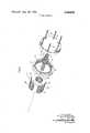
- FIG. 1composed of FIGS. 1A and 1B is an exploded, partially broken away, perspective view showing a powered wheel hub incorporating one embodiment of the invention
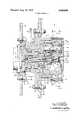
- FIG. 2is a side cross-sectional view showing the embodiment of FIG. 1;
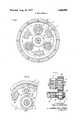
- FIG. 3is a cross-sectional view taken generally along the line 3-3 of FIG. 2;
- FIG. 4is a cross-sectional view taken generally along the line 4-4 of FIG. 2;
- FIG. 5is a cross-sectional view taken generally along the line 5-5 of FIG. 2;
- FIG. 6is a fragmentary cross-sectional view taken generally along the line 6-6 of FIG. 2;
- FIG. 7is a fragmentary side view showing the drive of the previous figures with the sun gear meshing with the second planet gears;
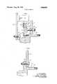
- FIG. 8is a fragmentary side cross-sectional view showing another embodiment of the invention which provides shifting between two gear ratios without any disassembly of the unit;
- FIG. 9is a fragmentary side cross-sectional view showing another embodiment of the invention incorporating a remotely controlled gear shifting mechanism
- FIG. 10is a fragmentary side cross-sectional view showing yet another embodiment of the invention incorporating another remotely controlled gear shifting mechanism
- FIG. 11is a fragmentary side cross-sectional view showing application of a braking system to the planetary reduction drive of the invention.
- FIG. 12is a fragmentary side cross-sectional view showing adaptation of the planetary reduction drive of the invention to drive a sprocket
- FIG. 13is a fragmentary cross-sectional view showing a further embodiment of the invention incorporating a disconnect.
- the planetary reduction drive hub of the inventioncomprises six readily assembled and disassembled major components, i.e., spindle and hub assembly 22, 24, fixed ring gear 26, planet carrier and gear cluster assembly 28, output ring gear 30, splined shaft and sun gear assembly 32, and cover 34.
- Mounting flange 36 of spindle 22is removably secured to frame element .38 of the vehicle by threaded fasteners 40.
- Drive motor 42commonly a hydraulic motor, is removably secured to flange 36 by threaded fasteners 44 and has its splined output shaft 46 extending into hollow spindle 48 and removably coupled to splined input shaft 50 by splined coupling 78.
- Wheel 54 having tire 56 thereonis removably secured to flange 58 of hub 24 by threaded fasteners 60.
- spindle assembly 22comprises mounting flange 36 having hollow spindle 48 extending outwardly from one side thereof.
- Flange 36is secured to vehicle frame element 38 by threaded fasteners 40, opening 62 in element 38 receiving boss 64 of flange 36.
- Flange 66 of motor 42is secured to boss 64 by threaded fasteners 44, motor 42 having boss 68 received in recess 70 in flange 36.
- Splined output shaft 46 of motor 42extends into hollow spindle 48.
- Splined input shaft 50has a first or inner portion 72 extending into hollow spindle 48 and a second or outer portion 74 extending outwardly from outer end 76 thereof.
- Motor shaft 46 and inner input shaft portion 72are removably connected by splined coupling 78, snap ring 80 properly positioning coupling 78.
- Fixed ring gear 26comprises a cup-shaped member having internal ring gear teeth 82 formed on its side wall 84. Fixed ring gear 26 is removably mounted on hollow spindle 48 adjacent outer end 76 by a splined connection comprising external splines 86 on hollow spindle 48 and internal splines 88 in end wall 90.
- Hub assembly 24comprises first orv inner hub portion 92 and second or outer hub portion 94.
- Inner hub portion 92is rotatably mounted on hollow spindle 48 between end wall 90 of fixed ring gear 26 and flange 36 by roller bearings 96.
- Seal 98prevents passage of lubricant out of inner hub portion 92.
- Outer hub portion 94concentrically surrounds fixed ring gear 26.
- Spacer 100 and snap ring 102retain bearings 96-and hub assembly 24 in assembled relationship on hollow spindle 48.
- Planet carrier 114is coaxially positioned within ring gears 26, 30 and rotatably supports three planet shafts 116.
- Each of the planet shafts 116has a gear cluster 118 thereon comprising first and second integrally formed planet gears 120, 122 which rotate in unison.
- Gear clusters 118are rotatably supported on planet shafts 116 by roller bearings 124 having spacer 126 therebetween.
- Planet shafts 116extend between and are supported by end walls 128, 130 of carrier 114, end walls 128, 130 being integrally connected by webs 132 disposed between gear clusters 118, as best seen in FIGS. 3 through 6. Planet shafts 116 are secured against rotation and axial movement by roll pins 134.
- Thrust washers 136are positioned between the opposite ends of gear clusters 118 and C-shaped bosses 138 formed on end walls 128, of carrier 114, as best seen in FIGS. 2, 3 and 6.
- Thrust washers 136have inwardly formed tangs 140 which extend between ends 142 of bosses 138 (FIGS. 3 and 6) thereby preventing rotation of thrust washers 136 with rotation of gear clusters 1 18 and reducing wear of bosses 138.
- Thrust washers 144are positioned between carrier end wall 128 and cover 34 and carrier end wall 130 and end wall 90 of fixed ring gear 26, respectively.
- First planet gears 120mesh with teeth 82 of fixed ringgear 26 and second planet gears 122 mesh with teeth 104 of output ring gear 30.
- sun gearhas a splined connection with outer portion 74 of splined input shaft 50 and meshes with first planet gears 120, sun gear 150 being retained in position by snap rings 152. It will be seen that the mesh of planet gears 120, 122 with ring gears 26, 30 provides the sole support for carrier 1 14.
- Flange 58is formed on hub assembly 24 generally intermediate inner hub portion 92 and outer hub portion 94.
- Wheel 54is removably mounted on flange 58 by threaded fasteners 60 having conventional lugs 154 thereon.
- the outer surface of inner hub portion 92preferably has a plurality of angular spaced slots 156 formed therein. Pin 158 may be inserted in a slot 156, as shown by the dashed lines in FIG. 2, thereby to pro vide a parking brake.
- Thrust washer 160is positioned between outer end 162 of splined shaft 50 and boss 164 on cover 34, thrust washer 160 having flange 166 seated in opening 168 in boss 164.
- Thrust washer 160also has tang 170 extending into slot 172 in boss 164 for preventing rotation of thrust washer 160 with rotation of splined input shaft 50 and thus inhibiting wear of boss 164.
- sun gear 150 of the previous figureshas been removed from outer portion 74 of splined shaft 50 and a different sun gear 174 positioned thereon in mesh with second planet gears 122, sun gear 174. being retained on splined input shaft portion 74 by snap rings 176.
- Snap rings 152may then be removed thus permitting removal of sun gear 150 from portion 74 of splined shaft 50.
- Sun gear 174may then be positioned on portion 74 of splined shaft 50 and retained by snap rings 176, and remaining components reassembled in reverse sequence.
- GEAR REDUCTION RATIOS gears 120Sun gear 174, being disengaged, merely free-wheels in response to rotation of gear clusters 118. Actuating member 186 and input shaft 50' are maintained in this position by engagement of detent notch 206 with detent ball 208.
- Actuation of actuating member 186 rearwardly to the position as shown in dashed lines at 200awill move outer end 162 of input shaft 50' rearwardly into recess 192 to the position shown in dashed lines at 1620, actuating member 186 and input shaft 50' being retained in this position by engagement of detent notch 204 with detent ball 208.
- splined section 178 on outer portion 74' of input shaft 50is positioned between splined sections 180, 182 of sun gears 150', 174, as shown in dashed lines at 1780, thus providing a neutral position.
- FIGS. 2 through 7 of the drawingsare roughly to onehalf scale.
- a planetary reduction drive hubas shown in FIGS. 2 through 7 with gearing providing a gear reduction ratio of 34.5/1, as shown in the tabulation above, and with a hydraulic motor 42 having two cubic inch per revolution displacement operated at 4,500 psi, provided approximately 50,000 pound inches of output torque.
- an elongated hollow spindle 48'is provided and inner portion 72' of input shaft 50' and splined coupling 78' are also elongated.
- Inner portion 72' of input shaft 50'is splined and outer portion 74' has a relatively short splined section 178 thereon.
- Two sun gears 150 and 174'are provided at all times respectively in mesh with planet gears 120, 122 of gear clusters 118.
- Sun gears 150', 174'have internally splined sections 180, 182, respectively.
- Sun gear 150has spacing portions 151 on its opposite sides. Spacer 153 locates sun gear 174.
- Annular groove 184is formed in outer portion 74' of input shaft 50' adjacent outer end 162 and shift actuating member 186 has end portion 188 received in groove 184.
- Cover 34'has an outwardly projecting hub portion 190 with a recess 192 formed therein coaxially with input shaft 50'.
- Actuating member 186extends through and is slideably received in slot 194 in recess 192 and opening 196 in end wall 198 of hub 190.
- Ac tuating knob 200is attached to the end of actuating member 186.
- Actuating member 186has three spaced apart detent notches 202, 204 and 206 formed therein, and a detent ball 208 biased inwardly by spring 210 is seated in opening 212 in hub 190.
- sun gear 174is driven thus driving planet gears 122.
- Sun gear being disengaged from outer portion 74' of input shaft 50'is free-wheeling. It will be seen that the elongated splined coupling 78' permits this axial shifting of inner portion 72' of input shaft 50'.
- flange 36" of spindle assembly 22has an enlarged boss 214 formed thereon from which hollow spindle 48'' ex tends.
- Sleeve 216surrounds outer portion 74 of splined input shaft 50 and has a splined connection therewith, as at 218.
- Sun gears 150" and 174"are rotatably mounted on sleeve 216.
- Flanges 220, 222are respectively formed on the opposite ends of sleeve 216 and respectively have clutch teeth 224, 226 formed thereon.
- Cooperating clutch teeth 228, 230are formed on the sides of sun gears 150", 174". Spacing portions 151" and spacer 186" locate sun gears 150", 174".
- Sleeve 216is shifted axially from a position in which its clutch teeth 224 drivingly engage clutch teeth 228 on sun gear 150", as shown in solid lines in FIG. 9, to a position in which its clutch teeth 226 drivingly engage clutch teeth 230 on sun gear 174", as shown in dashed lines at 220a, by push rod 232 engaging flange 220 on sleeve 216 and extending axially through opening 234 in spindle 48" into cavity 236 in boss 214.
- Projection 238 having cam surface 240 thereonis formed on inner end 242 of push rod 232 in cavity 236.
- Spring 244normally biases sleeve 216 to position 220a in which teeth 226 drivingly engage teeth 230 on sun gear 174".
- Remotely controlled actuator 246,which may be a fluid power cylinder or a solenoid, has extensible element 248 engaging cam surface 240.
- actuator 246to extend element 248 will move push rod 232 toward the right as viewed in FIG. 9
- Actuator 246is retained in opening 250 communicating with cavity 236 by spacer 252 and threaded plug 254.
- a parking brakemay also be employed in conjunction with the shifting mechanism shown in FIG. 9.
- Member 256 having teeth 258 thereonis normally accommodated in recess 260 in end 76 of hollow spindle 48".
- Push rod 262is connected to member 256 and extends axially through opening 264 in spindle 48" into cavity 236.
- Projection 266 on end 268 of push rod 262has cam surface 270 thereon.
- Spring 272normally biases push rod-262 so as to position member 256 and teeth 258 in recess 260.
- Remotely controlled fluid power or solenoid actuator 274has extensible element 276 cooperatively engaging cam surface 270.
- Flange 220 of sleeve 216has braking teeth 278 on its outer surface.
- actuator 274Remote actuation of actuator 274 to extend element 276 will move push rod 262 toward the right as viewed in FIG. 9 thus moving teeth 258 on member 256 into engagement with teeth 278 on sleeve 216, further moving sleeve 216 toward the right against spring 244 I thereby causing teeth 224 to engage teeth 228 on sun gear 150".
- sun gear 150is locked against rotation thereby locking the entire gear train.
- Actuator 274is retained in opening 275 communicating with cavity 236 by spacer 277 and threaded plug 279.
- sleeve 280surrounds outer portion 74 of splined shaft 50, being retained thereon by snap rings 282.
- Sun gears 150", 174"are rotatably mounted on sleeve 280.
- Sun gears 150", 174"respectively have driven clutch discs 284, 286 secured thereto, as by welding, and respectively spaced from their outer faces.
- Stationary clutch discs'288, 290are splined on outer portion 74 of splined input shaft 50, respectively abutting snap rings 282, and 292.
- Pressure clutch discs 294, 296respectively have splined connections with outer portion 74 of splined input shaft 50, driven discs 284, 286 being respectively positioned between stationary discs 288, 290 and pressure discs 294, 296.
- Stationary discs 288, 290 and pressure discs 294, 296are respectively normally biased apart by springs 298, 300.
- Pressure disc 294is moved toward the right as viewed in FIG. 10 thereby to engage driven disc 284 and to move it and sun gear 150" slightly toward the right so that disc 284 engages stationary disc 288, by push rod 232 which may be remotely actuated by actuator 246 (FIG. 9).
- push rod 232may be remotely actuated by actuator 246 (FIG. 9).
- actuator 246FIG. 9
- actuation of push rod 232clamps driven disc 284 between stationary disc 288 and pressure disc 294, both of which are splined on input shaft 50, thus drivingly connecting sun gear 150" to the input shaft.
- Pressure disc 296is moved toward the left as viewed in FIG. 10 thereby to engage driven disc 286 and to move it and sun gear 174" slightly toward the left so that driven disc 286 engages stationary disc 290, by
- Actuator 304is shown as a fluid power cylinder having its pressure line 310 coupled to line 312 by rotatable coupling 314. Actuation of actuator 304 to extend push rod 302 will clamp driven disc 286 between stationary disc 290 and pressure disc 296, both of which are splined to outer portions 74 of splined input shaft 50, thus drivingly connecting sun 8 gear 174" to the input shaft. It will further be seen that simultaneous actuation of actuator 246 (FIG. 9) and actuator 304 will result in connecting both sun gears and 174" to outer portion 74 of splined input shaft 50 thereby locking the gear train to provide a parking brake action.
- annular brake disc 316may be secured to the side of flange 58 remote from wheel 54 by threaded fasteners 318, disc 316 having suitable brake face material 320 thereon adjacent its outer periphery 322.
- Caliper mechanism 324is secured to frame element 38 by threaded fasteners 326 and has caliper arms 328, 330 straddling the peripheral region of disc 316. Braking action is provided by actuation of mechanism 324 to move caliper arms 328, 330 into braking engagement with braking surfaces 320 of brake disc 316.
- the planetary reduction drive hub of the inventionmay be employed for driving rotatable driven elements other than wheels, such as the drum of a transit mix concrete mixer.
- drive sprocket 332is secured to flange 58 of hub assembly 24 by threaded fasteners 334, sprocket 332 in turn driving a chain (not shown) which drives another rotatable driven element.
- disconnect member 336is provided which may be a separate element abutting end 162 of input shaft 50 or which may be formed as an integral extension of input shaft 50"".
- Disconnect member 336extends through opening 338 in hub portion 340 of .cover 34"", seal 342 preventing passage of lubricant along disconnect member 336.
- Disconnect cap 344has hollow hub portion 346 and annular flange portion 348 removably secured to hub 340 by threaded fasteners 350. In the driving position of the drive, end 3520f disconnect member 336 extends into hub portion 346 of disconnect cap 344, as shown in FIG. 13.
- disconnect cap 344is reversed so that hub portion 346 extends into cavity 354 in hub 340 thereby engaging end 352 of disconnect member 336 and moving it and input shaft 50"" to the left, as viewed in FIG. 13, thereby positioning inner input shaft portion 72 as shown in dashed lines at 356.
- output ring gear 10is integrally formed on cover 34"".
- Outer portion 74"" of input shaft 50"”has two splined sections 358, 360 thereon with unsplined portion 362 therebetween.
- splined section 358engages internal splines 364 on sun gear 150"" when that sun gear is employed
- splined section 360engages internal splines 366 on sun gear 174"" when that sun gear is employed, it being understood that while both sun gears 150"" and 174" are shown in FIG. 13, only one sun gear is utilized in the drive at any given time.
- Spacers 368, 370locate sun gear 150"" when that sun gear is employed, and spacers 372, 374 locate sun gear 174" when that sun gear is employed.
- a pair of spaced-apart snap rings 376, 378are seated in grooves on input shaft 50"" between inner portion 72 and splined portion 58.
- Retaining rings 380, 382are biased-apart by coil spring 384 and in the drive position of input shaft 50", respectively engage snap rings 376, 378.
- Coil spring 384 and retainer rings 380, 382are accommodated in recesses 386, 388 respectively formed in spindle 48 and in spacer 368 or 372, recesses 386, 388 respectively having shoulders 390, 392.
- disconnect cap 344when disconnect cap 344 is reversed as above described with hub portion 346 engaging end 352 of disconnect member 336, snap ring 378 engages retainer ring 382 thus compressing spring 384 against retainer ring 380 which engages shoulder .390 as inner end 72 of input shaft 50" moves to the left to the dashed line position 356.
- splined section 358will move to the left out of engagement with splines 364 of sun gear 150"" if that sun gear is employed, or splined section 360 will move to the left out of engagement with splines 366 of sun gear 174"" if that sun gear is employed, thus permitting free-wheeling of the planetary reduction drive.
- a planetary reduction drivecomprising: a mounting flange having a hollow spindle extending outwardly from one side thereof, said spindle having an outer end, means for securing said flange to a support member, and means for mounting a drive motor on the other side of said flange with its output shaft extending into said spindle; an input shaft coaxial with said motor shaft having a first portion extending into said spindle and a second portion extending outwardly from said outer end thereof; means for coupling said first portion of said input shaft to said motor shaft; a fixed ring gear coaxial with and surrounding said second portion of said input shaft, and means for securing said fixed ring gear to said spindle adjacent said outer end thereof; a housing having a first hub portion surrounding and rotatably mounted on said spindle, a second hub portion surrounding said fixed ring gear, and means for mounting a rotatable driven element on said housing; an output ring gear coaxial with and surrounding said second portion of said input shaft, secured to said second hub portion
- the drive of claim 5further comprising a cover member having a rim portion abutting said output ring gear, said last-named securing means comprising threaded fasteners securing said cover member and output ring gear to said outer end of said second hub portion.
- said splined connectioncomprises external splines extending substantially the length of said second portion of said input shaft, and mating internal splines on said sun gear removably connecting the same to said external splines whereby a selected sun gear may be selectively meshed with the first or second planet gears of said clusters.
- portion of said cover memberdefine a continuous cylindrical outer surface.
- said driven element mounting meanscomprises an annular flange intermediate said first and second hub portions of said housmg.
- each of said sun gearshas internal splines thereon, said second portion of said input shaft having an externally splined section,
- said selective connecting meanscomprising means for axially shifting said input shaft between a first position with said splined section engaging the internal splines of one of said pinions and a second position with said splined section engaging the internal splines of the other of said pinions.
- said selective connecting meanscomprises an axially movable sleeve surrounding and having a splined connection with said 17.
- said sun gearsare rotatably mounted on said second portion of said input shaft, each of said clutch means comprising a driven second portion of said input shaft and having opposite ends, said sun gears being rotatably mounted on said sleeve between said ends thereof, said sun gears respectively having clutch teeth on the sides thereof facing said ends of said sleeve, said sleeve having clutch teeth respectively formed on said opposite ends thereof, and means for selectively axially shifting said sleeve between a first position with the clutch teeth at one end thereof engaging the clutch teeth on one sun gear and with the clutch teeth at the other end disengaged from the clutch teeth on the other sun gear, and a second position with the clutch teeth at the other end of said sleeve engaging the clutch teeth on the other sun gear and the clutch teeth at said one end disengaged from the clutch teeth on said one sun gear
- said selective connecting meanscomprises first and second clutch means for respectively drivingly connecting said sun gears to said second portion of said input shaft.
- clutch discsecured to the respective sun gear and spaced therefrom, a stationary clutch disc secured to said second portion of said input shaft between said driven disc and the respective sun gear, a pressure clutch disc having a splined connection with said second portion of said input shaft, said driven disc being disposed from said stationary disc and pressure disc, spring means for normally biasing said pressure and stationary discs away from engagement with said driven disc, and means for selectively moving said pressure disctoward said driven disc thereby drivingly to clamp said driven disc between said stationary and i .ii1 i% e of claim 17 further comprising first actuator means mounted in said spindle for actuating the pressure disc of one of said clutch means, a cover member secured to said second hub portion of said housing, and second actuator means mounted in said cover for actuating the pressure disc of the other of said clutch means.
- said connecting meanscomprises a splined section on said input shaft and mating splines on said sun gear, said input shaft being axially movable between a drive position with said splined section engaging said sun gear splines, and a disconnected position with said splined section disengaged from said sun gear splines.
- the drive of claim 19further comprising spring means for normally biasing said input shaft to said drive position thereof, a cover member secured to said second hub portion, said cover member having a hub portion coaxial with said input shaft and having a coaxial opening therethrough, a disconnect member in said opening and axially movable therein with said input shaft between said positions thereof, and a disconnect cap removably secured to said cover member and covering said opening therein, said cap having a projection thereon, said cap being adapted to be secured to said cover member in a first position with said projection disengaged from said disconnect member, said spring means biasing said input shaft and disconnect member to said drive position in said first cap position, said cap being adapted to be secured to said cover member in a second position with said projection engaging said disconnect member and moving the same and said shaft to said disconnected position in said second cap position.
Landscapes
- Engineering & Computer Science (AREA)
- General Engineering & Computer Science (AREA)
- Mechanical Engineering (AREA)
- Chemical & Material Sciences (AREA)
- Combustion & Propulsion (AREA)
- Transportation (AREA)
- Retarders (AREA)
- Mechanical Operated Clutches (AREA)
Abstract
Description
Claims (20)
Applications Claiming Priority (1)
| Application Number | Priority Date | Filing Date | Title |
|---|---|---|---|
| US13270771A | 1971-04-09 | 1971-04-09 |
Publications (1)
| Publication Number | Publication Date |
|---|---|
| US3686978Atrue US3686978A (en) | 1972-08-29 |
Family
ID=22455240
Family Applications (1)
| Application Number | Title | Priority Date | Filing Date |
|---|---|---|---|
| US132707AExpired - LifetimeUS3686978A (en) | 1971-04-09 | 1971-04-09 | Plantetary reduction wheel hub |
Country Status (5)
| Country | Link |
|---|---|
| US (1) | US3686978A (en) |
| AU (1) | AU464551B2 (en) |
| CA (1) | CA960063A (en) |
| DE (1) | DE2217152C2 (en) |
| GB (1) | GB1384732A (en) |
Cited By (76)
| Publication number | Priority date | Publication date | Assignee | Title |
|---|---|---|---|---|
| US3797325A (en)* | 1971-06-07 | 1974-03-19 | Gearmatic Co Ltd | Two speed primary drive assembly for hydraulic winch |
| DE2361022A1 (en)* | 1972-12-04 | 1974-06-12 | Caterpillar Tractor Co | BRAKE ARRANGEMENT FOR THE PIVOT DRIVE OF AN EXCAVATOR |
| JPS5166967A (en)* | 1974-10-29 | 1976-06-10 | Eaton Corp | |
| US3969950A (en)* | 1974-03-04 | 1976-07-20 | Trw Inc. | Drive assembly |
| FR2330921A1 (en)* | 1975-11-05 | 1977-06-03 | Eaton Corp | Epicyclic gear reducer with central drive shaft - has combined hydraulic swash plate incorporated in same casing for use on road vehicle |
| JPS5276877U (en)* | 1976-11-18 | 1977-06-08 | ||
| FR2352995A1 (en)* | 1976-05-24 | 1977-12-23 | Trw Inc | Drive unit for e.g. mixer, winch or vehicle - has toothed gears between bearings and coupled to input shaft and driving collar |
| FR2357395A1 (en)* | 1976-07-05 | 1978-02-03 | Hurth Masch Zahnrad Carl | WHEEL CONTROL DEVICE FOR HANDLING TROLLEYS |
| US4083421A (en)* | 1976-12-06 | 1978-04-11 | Horn Ronald L Van | Two speed motorcycle hub transmission |
| FR2405154A1 (en)* | 1977-10-06 | 1979-05-04 | Zahnradfabrik Friedrichshafen | INDIVIDUAL WHEEL DRIVE MECHANISM FOR MACHINE TOOLS |
| WO1981000899A1 (en)* | 1979-09-04 | 1981-04-02 | J Eichorst | Floating planet gear system |
| US4417485A (en)* | 1979-09-07 | 1983-11-29 | Fairfield Manufacturing Co., Inc. | Coupled planetary gear speed reducer for use in industrial vehicles |
| US4431073A (en)* | 1981-12-03 | 1984-02-14 | Fairfield Manufacturing Co., Inc. | Two speed final drive gear box |
| US4604915A (en)* | 1982-12-10 | 1986-08-12 | Ing. H.C.F. Porsche Ag | Drive system for a rotary-, pivot-, and propelling-drive of a vehicle especially of an excavating machine |
| US5302160A (en)* | 1989-03-28 | 1994-04-12 | Jatco Corporation | Planet-pinion carrier assembly for planetary gear system |
| US5376057A (en)* | 1993-07-08 | 1994-12-27 | Ingersoll-Rand Company | Multistage differential gear package |
| US5385514A (en)* | 1993-08-11 | 1995-01-31 | Excelermalic Inc. | High ratio planetary transmission |
| US5435794A (en)* | 1992-04-08 | 1995-07-25 | Nissan Motor Co., Ltd. | Power transmission unit for electric vehicle |
| US5846154A (en)* | 1996-10-15 | 1998-12-08 | Handycare | Single speed gear assembly for a wheelchair |
| DE19756966A1 (en)* | 1997-12-20 | 1999-06-24 | Zahnradfabrik Friedrichshafen | Planetary gear with sun wheel on central shaft |
| US6199652B1 (en) | 1997-12-11 | 2001-03-13 | Vectrix Corporation | Vehicle drive wheel assembly |
| US6199651B1 (en) | 1997-12-11 | 2001-03-13 | Vectrix Corporation | Vehicle drive wheel assembly |
| DE10029540A1 (en)* | 2000-06-15 | 2002-01-03 | Sauer Danfoss Nordborg As Nord | Hydraulic drive assembly has hydraulic motor and output device set against holder from opposite sides with motor connected to holder through its connection with the output device |
| US20020119860A1 (en)* | 2000-10-10 | 2002-08-29 | Strong Victor R. | Two speed gear box |
| US6481518B1 (en)* | 2001-08-07 | 2002-11-19 | David Wu | Motor drive mounting arrangement for golf cart |
| GB2377740A (en)* | 2001-07-19 | 2003-01-22 | Luk Lamellen & Kupplungsbau | Electric motor actuator having planetary reduction gear |
| US20030217878A1 (en)* | 2002-05-23 | 2003-11-27 | Tzora Active Systems Ltd. | Hub motor |
| FR2846226A1 (en)* | 2002-10-23 | 2004-04-30 | Alain Martinot | Roller assembly for wheelchair comprises shaft on which planet pinion and satellite carrier are mounted, carrier supporting satellite pinion interposed between planet pinion and notched crown wheel connected to wheel hub |
| US6811510B1 (en)* | 2002-09-03 | 2004-11-02 | Hydro-Gear Limited Partnership | Hydraulic motor apparatus and vehicle |
| US6811509B1 (en) | 2002-09-03 | 2004-11-02 | Hydro-Gear Limited Partnership | Hydraulic motor apparatus including brake mechanism |
| US6840879B1 (en) | 2002-09-03 | 2005-01-11 | Hydro-Gear Limited Partnership | Hydraulic motor apparatus |
| US20050023056A1 (en)* | 2003-07-31 | 2005-02-03 | Clive Harrup | Electric motor and gear drive assembly for driving a vehicle wheel |
| DE102004003645A1 (en)* | 2004-01-24 | 2005-08-11 | Zf Friedrichshafen Ag | Portal axle drive for e.g. low-floor omnibus, has two stage gear reduction built through gear wheels that are assembled on same shaft, and split ring arranged between two wheels or between one wheel and output side of intermediate shaft |
| US20050232527A1 (en)* | 2004-04-16 | 2005-10-20 | Nsk Ltd. | Radial needle-like roller bearing and pinion shaft |
| EP1331127A3 (en)* | 2002-01-23 | 2005-11-30 | AxleTech International IP Holdings, LLC | Electric drive unit assembly for heavy duty vehicles |
| US7081061B1 (en) | 2002-09-03 | 2006-07-25 | Hydro-Gear Limited Partnership | Hydraulic motor apparatus |
| EP1396660A3 (en)* | 2002-09-03 | 2006-12-06 | Carraro S.P.A. | An imbricate type epicyclic reduction gear |
| WO2006102906A3 (en)* | 2005-04-01 | 2006-12-14 | Colive Aps | A planet gear |
| US20080023240A1 (en)* | 2006-07-28 | 2008-01-31 | Richard Larry Sunsdahl | Side-by-side ATV |
| US20090178871A1 (en)* | 2006-07-28 | 2009-07-16 | Richard Larry Sunsdahl | Side-by-side atv |
| CN101528519A (en)* | 2006-10-18 | 2009-09-09 | 卢卡斯汽车股份有限公司 | Single-part carrier for an electric parking brake actuator with planetary gear set |
| US20090285517A1 (en)* | 2008-05-15 | 2009-11-19 | Ulrich Eckel | Drive facility |
| US20090320626A1 (en)* | 2008-06-26 | 2009-12-31 | Hiwin Mikrosystem Corp. | Actuator |
| CN1757954B (en)* | 2004-06-25 | 2010-08-25 | 布雷维尼里杜托利股份公司 | Decelerater special for extruser |
| CN101672346B (en)* | 2009-10-13 | 2011-04-13 | 郑州机械研究所 | Rocket movable launcher supporting arm speed reducer |
| WO2011098181A1 (en)* | 2010-02-10 | 2011-08-18 | Zf Friedrichshafen Ag | Arrangement for driving a vehicle wheel with a drive motor |
| US20120031212A1 (en)* | 2010-08-04 | 2012-02-09 | Auburn Gear, Inc. | Quick disconnect for a drive unit |
| US20120060276A1 (en)* | 2010-09-10 | 2012-03-15 | Heidlage John K | Height Adjustable Bed Framework with a Lift Chain and a Planetary Gear Train |
| US8262533B2 (en) | 2006-04-30 | 2012-09-11 | Tomatech A/S | Transmission |
| JP2012214147A (en)* | 2011-03-31 | 2012-11-08 | Honda Motor Co Ltd | Electric vehicle |
| US20130237370A1 (en)* | 2012-03-10 | 2013-09-12 | Romax Technology Limited | Pin Retainer |
| US8627737B2 (en) | 2011-03-16 | 2014-01-14 | Caterpillar Inc. | Spur gear final drive with integrated brakes |
| EP2881625A1 (en)* | 2013-12-06 | 2015-06-10 | Technology Investments Limited | A planetary gear hub assembly |
| WO2015106896A1 (en)* | 2014-01-16 | 2015-07-23 | Zf Friedrichshafen Ag | Stepped planetary gear with inner bearing |
| CN106050960A (en)* | 2016-06-28 | 2016-10-26 | 北京特种机械研究所 | Industrial car axle structure |
| US9531237B2 (en) | 2013-12-19 | 2016-12-27 | Gustomsc Resources B.V. | Dual rack output pinion drive |
| KR20170009924A (en)* | 2014-05-27 | 2017-01-25 | 스카니아 씨브이 악티에볼라그 | Gearbox for vehicles and vehicles comprising such a gearbox |
| WO2017115795A1 (en)* | 2015-12-28 | 2017-07-06 | 本田技研工業株式会社 | Planetary gear mechanism |
| EP3152464A4 (en)* | 2014-05-27 | 2018-01-24 | Scania CV AB | Gearbox for vehicles and vehicles comprising such a gearbox |
| EP3149359A4 (en)* | 2014-05-27 | 2018-02-21 | Scania CV AB | Gearbox for vehicles and vehicle, comprising such a gearbox |
| WO2018034647A1 (en)* | 2016-08-15 | 2018-02-22 | Auburn Gear, Inc. | Wheel drive transmission |
| WO2018115916A1 (en)* | 2016-12-20 | 2018-06-28 | Volvo Truck Corporation | An assembly for a vehicle axle including a differential |
| WO2018164723A1 (en)* | 2017-03-06 | 2018-09-13 | Fairfield Manufacturing Company, Inc. | Planetary wheel drive using bushings |
| WO2019057397A1 (en)* | 2017-09-22 | 2019-03-28 | Saf-Holland Gmbh | HOUSING UNIT AND AXLE ASSEMBLY |
| US10246147B2 (en)* | 2015-08-27 | 2019-04-02 | Scaip S.P.A. | Industrial vehicle with device for releasing the undercarriages without disconnecting the hydraulic system |
| EP3922886A1 (en)* | 2020-06-11 | 2021-12-15 | Safran Transmission Systems | Mechanical gear for aircraft turbine engine |
| US11371590B2 (en)* | 2017-07-21 | 2022-06-28 | Ge Avio S.R.L. | Gear transmission for aeronautical applications |
| US11420760B2 (en)* | 2020-06-29 | 2022-08-23 | Textron Innovations Inc. | Sealed coaxial input and output shafts |
| US20230243416A1 (en)* | 2022-02-01 | 2023-08-03 | Nachi-Fujikoshi Corp. | Planetary gear mechanism with free-wheel mechanism |
| US11731779B2 (en) | 2020-06-01 | 2023-08-22 | Textron Innovations Inc. | Drivetrain for an aircraft including gearbox with coaxial input and output shafts |
| IT202200009842A1 (en)* | 2022-05-12 | 2023-11-12 | Iveco Spa | VEHICLE AXLE WHEEL HUB INCLUDING AN IMPROVED INTEGRATED REDUCTION SYSTEM |
| EP4002988A4 (en)* | 2019-07-26 | 2023-11-22 | Generac Power Systems, Inc. | Battery-operated electric mower |
| US11852221B2 (en)* | 2022-03-18 | 2023-12-26 | Rexon Industrial Corp., Ltd. | Planetary gear assembly |
| US20240255043A1 (en)* | 2021-05-25 | 2024-08-01 | Diakont S.r.l. | Planetary gear reducer with at least one planet gear with at least one external thread portion |
| WO2024201411A1 (en) | 2023-03-31 | 2024-10-03 | Eaton Intelligent Power Limited | Axle disconnect arrangement |
| US12397906B2 (en)* | 2022-09-16 | 2025-08-26 | Safran Transmission Systems | Device for driving at least one wheel of an aircraft landing gear |
Families Citing this family (6)
| Publication number | Priority date | Publication date | Assignee | Title |
|---|---|---|---|---|
| SE409497B (en) | 1978-10-02 | 1979-08-20 | Jonsson Sven | GEAR AND PROCEDURE AND APPLIANCE FOR ITS MANUFACTURE |
| GB0316290D0 (en) | 2003-07-11 | 2003-08-13 | Glaxo Group Ltd | Novel compounds |
| DE102016201226B4 (en)* | 2016-01-28 | 2017-11-02 | Schaeffler Technologies AG & Co. KG | Planetary gear for a motor vehicle |
| US11554663B2 (en)* | 2018-09-11 | 2023-01-17 | Volvo Construction Equipment Ab | Wheel hub drive system |
| CN114352185B (en)* | 2021-12-13 | 2024-01-02 | 广东君豪高科地下空间建设有限公司 | Variable speed drill bit for underground space development field |
| DE102023002616A1 (en) | 2022-07-28 | 2024-02-08 | Sew-Eurodrive Gmbh & Co Kg | Drive unit, in particular for a vehicle, and vehicle with a drive unit |
Citations (7)
| Publication number | Priority date | Publication date | Assignee | Title |
|---|---|---|---|---|
| US1632123A (en)* | 1924-04-02 | 1927-06-14 | Westinghouse Electric & Mfg Co | Reduction-gear transmission |
| US1707877A (en)* | 1927-06-18 | 1929-04-02 | Alvin L Roberts | Reducing gear |
| US1799740A (en)* | 1929-09-03 | 1931-04-07 | Felton George William | Gearing mechanism for changing speed ratios |
| US2401875A (en)* | 1944-04-01 | 1946-06-11 | Frank P Lawler | Reduction gear drive |
| US2402756A (en)* | 1944-10-19 | 1946-06-25 | Charles H Grant | Hoist |
| US3319492A (en)* | 1964-08-20 | 1967-05-16 | Pacific Car & Foundry Co | Multi-stage reduction geared winch |
| US3502166A (en)* | 1968-07-19 | 1970-03-24 | Gen Motors Corp | Power wheel drive assembly |
Family Cites Families (10)
| Publication number | Priority date | Publication date | Assignee | Title |
|---|---|---|---|---|
| US3097546A (en) | 1963-07-16 | Transmission mechanism | ||
| DE1252499B (en)* | 1967-10-19 | |||
| FR544531A (en)* | 1921-12-13 | 1922-09-23 | Lancashire Dynamo And Motor Co | Improvements to devices used to vary the speed ratio and the relative direction of rotation of two rotary members |
| US1919924A (en)* | 1930-12-01 | 1933-07-25 | Walker Vehicle Co | Wheel |
| FR771033A (en)* | 1933-06-21 | 1934-09-28 | Speed transformer | |
| US2726726A (en)* | 1950-08-23 | 1955-12-13 | Letourneau Inc | Electric vehicle wheel |
| US2801702A (en)* | 1953-05-06 | 1957-08-06 | Gen Motors Corp | Steerable driving axle |
| FR1298663A (en)* | 1961-08-24 | 1962-07-13 | Coventry Climax Eng Ltd | Built-in motor wheel |
| GB1120662A (en)* | 1966-05-11 | 1968-07-24 | Alfred Reginald Erwin Arnot | Motorised wheel traction drive units |
| US3459070A (en)* | 1967-07-03 | 1969-08-05 | Borg Warner | Wheel drive mechanism |
- 1971
- 1971-04-09USUS132707Apatent/US3686978A/ennot_activeExpired - Lifetime
- 1972
- 1972-03-16CACA137,225Apatent/CA960063A/ennot_activeExpired
- 1972-03-21GBGB1324972Apatent/GB1384732A/ennot_activeExpired
- 1972-03-23AUAU40324/72Apatent/AU464551B2/ennot_activeExpired
- 1972-04-10DEDE2217152Apatent/DE2217152C2/ennot_activeExpired
Patent Citations (7)
| Publication number | Priority date | Publication date | Assignee | Title |
|---|---|---|---|---|
| US1632123A (en)* | 1924-04-02 | 1927-06-14 | Westinghouse Electric & Mfg Co | Reduction-gear transmission |
| US1707877A (en)* | 1927-06-18 | 1929-04-02 | Alvin L Roberts | Reducing gear |
| US1799740A (en)* | 1929-09-03 | 1931-04-07 | Felton George William | Gearing mechanism for changing speed ratios |
| US2401875A (en)* | 1944-04-01 | 1946-06-11 | Frank P Lawler | Reduction gear drive |
| US2402756A (en)* | 1944-10-19 | 1946-06-25 | Charles H Grant | Hoist |
| US3319492A (en)* | 1964-08-20 | 1967-05-16 | Pacific Car & Foundry Co | Multi-stage reduction geared winch |
| US3502166A (en)* | 1968-07-19 | 1970-03-24 | Gen Motors Corp | Power wheel drive assembly |
Cited By (114)
| Publication number | Priority date | Publication date | Assignee | Title |
|---|---|---|---|---|
| US3797325A (en)* | 1971-06-07 | 1974-03-19 | Gearmatic Co Ltd | Two speed primary drive assembly for hydraulic winch |
| DE2361022A1 (en)* | 1972-12-04 | 1974-06-12 | Caterpillar Tractor Co | BRAKE ARRANGEMENT FOR THE PIVOT DRIVE OF AN EXCAVATOR |
| US3969950A (en)* | 1974-03-04 | 1976-07-20 | Trw Inc. | Drive assembly |
| JPS5166967A (en)* | 1974-10-29 | 1976-06-10 | Eaton Corp | |
| US4040312A (en)* | 1974-10-29 | 1977-08-09 | Eaton Corporation | Planetary reduction drive unit |
| FR2330921A1 (en)* | 1975-11-05 | 1977-06-03 | Eaton Corp | Epicyclic gear reducer with central drive shaft - has combined hydraulic swash plate incorporated in same casing for use on road vehicle |
| FR2352995A1 (en)* | 1976-05-24 | 1977-12-23 | Trw Inc | Drive unit for e.g. mixer, winch or vehicle - has toothed gears between bearings and coupled to input shaft and driving collar |
| FR2357395A1 (en)* | 1976-07-05 | 1978-02-03 | Hurth Masch Zahnrad Carl | WHEEL CONTROL DEVICE FOR HANDLING TROLLEYS |
| JPS5276877U (en)* | 1976-11-18 | 1977-06-08 | ||
| US4083421A (en)* | 1976-12-06 | 1978-04-11 | Horn Ronald L Van | Two speed motorcycle hub transmission |
| FR2405154A1 (en)* | 1977-10-06 | 1979-05-04 | Zahnradfabrik Friedrichshafen | INDIVIDUAL WHEEL DRIVE MECHANISM FOR MACHINE TOOLS |
| US4275616A (en)* | 1977-10-06 | 1981-06-30 | Zahnradfabrik Friedrichshafen Ag | Hydraulic wheel drive |
| WO1981000899A1 (en)* | 1979-09-04 | 1981-04-02 | J Eichorst | Floating planet gear system |
| US4459876A (en)* | 1979-09-04 | 1984-07-17 | Caterpillar Tractor Co. | Floating planet gear system |
| US4417485A (en)* | 1979-09-07 | 1983-11-29 | Fairfield Manufacturing Co., Inc. | Coupled planetary gear speed reducer for use in industrial vehicles |
| US4431073A (en)* | 1981-12-03 | 1984-02-14 | Fairfield Manufacturing Co., Inc. | Two speed final drive gear box |
| US4604915A (en)* | 1982-12-10 | 1986-08-12 | Ing. H.C.F. Porsche Ag | Drive system for a rotary-, pivot-, and propelling-drive of a vehicle especially of an excavating machine |
| US5302160A (en)* | 1989-03-28 | 1994-04-12 | Jatco Corporation | Planet-pinion carrier assembly for planetary gear system |
| US5435794A (en)* | 1992-04-08 | 1995-07-25 | Nissan Motor Co., Ltd. | Power transmission unit for electric vehicle |
| US5376057A (en)* | 1993-07-08 | 1994-12-27 | Ingersoll-Rand Company | Multistage differential gear package |
| US5385514A (en)* | 1993-08-11 | 1995-01-31 | Excelermalic Inc. | High ratio planetary transmission |
| US5846154A (en)* | 1996-10-15 | 1998-12-08 | Handycare | Single speed gear assembly for a wheelchair |
| US6199651B1 (en) | 1997-12-11 | 2001-03-13 | Vectrix Corporation | Vehicle drive wheel assembly |
| US6199652B1 (en) | 1997-12-11 | 2001-03-13 | Vectrix Corporation | Vehicle drive wheel assembly |
| DE19756966A1 (en)* | 1997-12-20 | 1999-06-24 | Zahnradfabrik Friedrichshafen | Planetary gear with sun wheel on central shaft |
| DE10029540A1 (en)* | 2000-06-15 | 2002-01-03 | Sauer Danfoss Nordborg As Nord | Hydraulic drive assembly has hydraulic motor and output device set against holder from opposite sides with motor connected to holder through its connection with the output device |
| US20020119860A1 (en)* | 2000-10-10 | 2002-08-29 | Strong Victor R. | Two speed gear box |
| US6616567B2 (en)* | 2000-10-10 | 2003-09-09 | Terex Corporation | Two speed gear box |
| GB2377740A (en)* | 2001-07-19 | 2003-01-22 | Luk Lamellen & Kupplungsbau | Electric motor actuator having planetary reduction gear |
| US6481518B1 (en)* | 2001-08-07 | 2002-11-19 | David Wu | Motor drive mounting arrangement for golf cart |
| EP1331127A3 (en)* | 2002-01-23 | 2005-11-30 | AxleTech International IP Holdings, LLC | Electric drive unit assembly for heavy duty vehicles |
| US20030217878A1 (en)* | 2002-05-23 | 2003-11-27 | Tzora Active Systems Ltd. | Hub motor |
| US7249643B2 (en)* | 2002-05-23 | 2007-07-31 | Tzora Active Systems Ltd. | Hub motor |
| EP1396660A3 (en)* | 2002-09-03 | 2006-12-06 | Carraro S.P.A. | An imbricate type epicyclic reduction gear |
| US7081061B1 (en) | 2002-09-03 | 2006-07-25 | Hydro-Gear Limited Partnership | Hydraulic motor apparatus |
| US7476172B1 (en) | 2002-09-03 | 2009-01-13 | Hydro-Gear Limited Partnership | Motor apparatus including brake mechanism |
| US7409890B1 (en) | 2002-09-03 | 2008-08-12 | Hydro-Gear Limited Partnership | Hydraulic motor apparatus |
| US6811509B1 (en) | 2002-09-03 | 2004-11-02 | Hydro-Gear Limited Partnership | Hydraulic motor apparatus including brake mechanism |
| US6811510B1 (en)* | 2002-09-03 | 2004-11-02 | Hydro-Gear Limited Partnership | Hydraulic motor apparatus and vehicle |
| US6997839B1 (en) | 2002-09-03 | 2006-02-14 | Hydro-Gear Limited Partnership | Hydraulic motor apparatus |
| US6840879B1 (en) | 2002-09-03 | 2005-01-11 | Hydro-Gear Limited Partnership | Hydraulic motor apparatus |
| US7927245B1 (en) | 2002-09-03 | 2011-04-19 | Hydro-Gear Limited Partnership | Hydraulic motor apparatus |
| US8221276B1 (en) | 2002-09-03 | 2012-07-17 | Hydro-Gear Limited Partnership | Hydraulic motor apparatus |
| US7476171B1 (en) | 2002-09-03 | 2009-01-13 | Hydro-Gear Limited Partnership | Hydraulic motor apparatus including brake mechanism |
| FR2846226A1 (en)* | 2002-10-23 | 2004-04-30 | Alain Martinot | Roller assembly for wheelchair comprises shaft on which planet pinion and satellite carrier are mounted, carrier supporting satellite pinion interposed between planet pinion and notched crown wheel connected to wheel hub |
| US7458433B2 (en)* | 2003-07-31 | 2008-12-02 | Arvinmeritor Technology, Llc | Electric motor and gear drive assembly for driving a vehicle wheel |
| US20050023056A1 (en)* | 2003-07-31 | 2005-02-03 | Clive Harrup | Electric motor and gear drive assembly for driving a vehicle wheel |
| DE102004003645A1 (en)* | 2004-01-24 | 2005-08-11 | Zf Friedrichshafen Ag | Portal axle drive for e.g. low-floor omnibus, has two stage gear reduction built through gear wheels that are assembled on same shaft, and split ring arranged between two wheels or between one wheel and output side of intermediate shaft |
| US20050232527A1 (en)* | 2004-04-16 | 2005-10-20 | Nsk Ltd. | Radial needle-like roller bearing and pinion shaft |
| US7276012B2 (en)* | 2004-04-16 | 2007-10-02 | Nsk Ltd. | Radial needle-like roller bearing and pinion shaft |
| CN1757954B (en)* | 2004-06-25 | 2010-08-25 | 布雷维尼里杜托利股份公司 | Decelerater special for extruser |
| CN101171442B (en)* | 2005-04-01 | 2010-06-23 | 托马克技术公司 | Planetary gear |
| JP2008534872A (en)* | 2005-04-01 | 2008-08-28 | トマクテック・アクティーゼルスカブ | Planetary gear |
| US20090233754A1 (en)* | 2005-04-01 | 2009-09-17 | Troels Pedersen | Planet Gear |
| WO2006102906A3 (en)* | 2005-04-01 | 2006-12-14 | Colive Aps | A planet gear |
| US8262533B2 (en) | 2006-04-30 | 2012-09-11 | Tomatech A/S | Transmission |
| US8827028B2 (en)* | 2006-07-28 | 2014-09-09 | Polaris Industries Inc. | Side-by-side ATV |
| US20090178871A1 (en)* | 2006-07-28 | 2009-07-16 | Richard Larry Sunsdahl | Side-by-side atv |
| US20110048828A1 (en)* | 2006-07-28 | 2011-03-03 | Polaris Industries Inc. | Side-by-side ATV |
| US20080023240A1 (en)* | 2006-07-28 | 2008-01-31 | Richard Larry Sunsdahl | Side-by-side ATV |
| US8596405B2 (en) | 2006-07-28 | 2013-12-03 | Polaris Industries Inc. | Side-by-side ATV |
| US8382125B2 (en) | 2006-07-28 | 2013-02-26 | Polaris Industries Inc. | Side-by-side ATV |
| CN101528519A (en)* | 2006-10-18 | 2009-09-09 | 卢卡斯汽车股份有限公司 | Single-part carrier for an electric parking brake actuator with planetary gear set |
| US20090285517A1 (en)* | 2008-05-15 | 2009-11-19 | Ulrich Eckel | Drive facility |
| US20090320626A1 (en)* | 2008-06-26 | 2009-12-31 | Hiwin Mikrosystem Corp. | Actuator |
| CN101672346B (en)* | 2009-10-13 | 2011-04-13 | 郑州机械研究所 | Rocket movable launcher supporting arm speed reducer |
| CN102753377A (en)* | 2010-02-10 | 2012-10-24 | Zf腓特烈斯哈芬股份公司 | Arrangement for driving a vehicle wheel with a drive motor |
| CN102753377B (en)* | 2010-02-10 | 2016-03-30 | Zf腓特烈斯哈芬股份公司 | For driving the device with CD-ROM drive motor of wheel |
| WO2011098181A1 (en)* | 2010-02-10 | 2011-08-18 | Zf Friedrichshafen Ag | Arrangement for driving a vehicle wheel with a drive motor |
| US20120031212A1 (en)* | 2010-08-04 | 2012-02-09 | Auburn Gear, Inc. | Quick disconnect for a drive unit |
| US8795130B2 (en)* | 2010-08-04 | 2014-08-05 | Auburn Gear, Inc. | Quick disconnect for a drive unit |
| US20120060276A1 (en)* | 2010-09-10 | 2012-03-15 | Heidlage John K | Height Adjustable Bed Framework with a Lift Chain and a Planetary Gear Train |
| US9737149B2 (en)* | 2010-09-10 | 2017-08-22 | Hill-Rom Services, Inc. | Height adjustable bed framework with a lift chain and a planetary gear train |
| US8627737B2 (en) | 2011-03-16 | 2014-01-14 | Caterpillar Inc. | Spur gear final drive with integrated brakes |
| JP2012214147A (en)* | 2011-03-31 | 2012-11-08 | Honda Motor Co Ltd | Electric vehicle |
| US8858382B2 (en)* | 2012-03-10 | 2014-10-14 | Romax Technology Limited | Pin retainer |
| US20130237370A1 (en)* | 2012-03-10 | 2013-09-12 | Romax Technology Limited | Pin Retainer |
| WO2015082157A1 (en)* | 2013-12-06 | 2015-06-11 | Technology Investments Limited | A planetary gear hub assembly |
| KR20160094994A (en)* | 2013-12-06 | 2016-08-10 | 테크놀로지 인베스트먼츠 리미티드 | A planetary gear hub assembly |
| RU2673132C1 (en)* | 2013-12-06 | 2018-11-22 | Текнолоджи Инвестментс Лимитед | Hub assembly of planetary gear |
| EP2881625A1 (en)* | 2013-12-06 | 2015-06-10 | Technology Investments Limited | A planetary gear hub assembly |
| US9531237B2 (en) | 2013-12-19 | 2016-12-27 | Gustomsc Resources B.V. | Dual rack output pinion drive |
| WO2015106896A1 (en)* | 2014-01-16 | 2015-07-23 | Zf Friedrichshafen Ag | Stepped planetary gear with inner bearing |
| KR20170009924A (en)* | 2014-05-27 | 2017-01-25 | 스카니아 씨브이 악티에볼라그 | Gearbox for vehicles and vehicles comprising such a gearbox |
| EP3152464A4 (en)* | 2014-05-27 | 2018-01-24 | Scania CV AB | Gearbox for vehicles and vehicles comprising such a gearbox |
| EP3149359A4 (en)* | 2014-05-27 | 2018-02-21 | Scania CV AB | Gearbox for vehicles and vehicle, comprising such a gearbox |
| US10018259B2 (en) | 2014-05-27 | 2018-07-10 | Scania Cv Ab | Gearbox for vehicles and vehicles comprising such a gearbox |
| US10246147B2 (en)* | 2015-08-27 | 2019-04-02 | Scaip S.P.A. | Industrial vehicle with device for releasing the undercarriages without disconnecting the hydraulic system |
| JPWO2017115795A1 (en)* | 2015-12-28 | 2018-08-09 | 本田技研工業株式会社 | Planetary gear mechanism |
| WO2017115795A1 (en)* | 2015-12-28 | 2017-07-06 | 本田技研工業株式会社 | Planetary gear mechanism |
| CN106050960B (en)* | 2016-06-28 | 2019-03-01 | 北京特种机械研究所 | A kind of industrial truck shafting structure |
| CN106050960A (en)* | 2016-06-28 | 2016-10-26 | 北京特种机械研究所 | Industrial car axle structure |
| US10766361B2 (en) | 2016-08-15 | 2020-09-08 | Auburn Gear, Inc. | Wheel drive transmission |
| WO2018034647A1 (en)* | 2016-08-15 | 2018-02-22 | Auburn Gear, Inc. | Wheel drive transmission |
| WO2018115916A1 (en)* | 2016-12-20 | 2018-06-28 | Volvo Truck Corporation | An assembly for a vehicle axle including a differential |
| US10710406B1 (en) | 2016-12-20 | 2020-07-14 | Volvo Truck Corporation | Assembly for a vehicle axle including a differential |
| CN110049880A (en)* | 2016-12-20 | 2019-07-23 | 沃尔沃卡车集团 | Component for the vehicle axles including differential mechanism |
| CN110049880B (en)* | 2016-12-20 | 2020-06-30 | 沃尔沃卡车集团 | Assembly for vehicle axle comprising a differential |
| WO2018164723A1 (en)* | 2017-03-06 | 2018-09-13 | Fairfield Manufacturing Company, Inc. | Planetary wheel drive using bushings |
| US11371590B2 (en)* | 2017-07-21 | 2022-06-28 | Ge Avio S.R.L. | Gear transmission for aeronautical applications |
| US11602953B2 (en) | 2017-09-22 | 2023-03-14 | Saf-Holland Gmbh | Housing unit and axle assembly |
| WO2019057397A1 (en)* | 2017-09-22 | 2019-03-28 | Saf-Holland Gmbh | HOUSING UNIT AND AXLE ASSEMBLY |
| EP4002988A4 (en)* | 2019-07-26 | 2023-11-22 | Generac Power Systems, Inc. | Battery-operated electric mower |
| US11731779B2 (en) | 2020-06-01 | 2023-08-22 | Textron Innovations Inc. | Drivetrain for an aircraft including gearbox with coaxial input and output shafts |
| EP3922886A1 (en)* | 2020-06-11 | 2021-12-15 | Safran Transmission Systems | Mechanical gear for aircraft turbine engine |
| FR3111400A1 (en)* | 2020-06-11 | 2021-12-17 | Safran Transmission Systems | AIRCRAFT TURBOMACHINE MECHANICAL REDUCER |
| US11420760B2 (en)* | 2020-06-29 | 2022-08-23 | Textron Innovations Inc. | Sealed coaxial input and output shafts |
| US20240255043A1 (en)* | 2021-05-25 | 2024-08-01 | Diakont S.r.l. | Planetary gear reducer with at least one planet gear with at least one external thread portion |
| US20230243416A1 (en)* | 2022-02-01 | 2023-08-03 | Nachi-Fujikoshi Corp. | Planetary gear mechanism with free-wheel mechanism |
| US11852221B2 (en)* | 2022-03-18 | 2023-12-26 | Rexon Industrial Corp., Ltd. | Planetary gear assembly |
| WO2023218379A1 (en)* | 2022-05-12 | 2023-11-16 | Iveco S.P.A. | Wheel hub for an axle of a vehicle comprising an improved integrated reduction system |
| IT202200009842A1 (en)* | 2022-05-12 | 2023-11-12 | Iveco Spa | VEHICLE AXLE WHEEL HUB INCLUDING AN IMPROVED INTEGRATED REDUCTION SYSTEM |
| US12397906B2 (en)* | 2022-09-16 | 2025-08-26 | Safran Transmission Systems | Device for driving at least one wheel of an aircraft landing gear |
| WO2024201411A1 (en) | 2023-03-31 | 2024-10-03 | Eaton Intelligent Power Limited | Axle disconnect arrangement |
Also Published As
| Publication number | Publication date |
|---|---|
| GB1384732A (en) | 1975-02-19 |
| CA960063A (en) | 1974-12-31 |
| AU4032472A (en) | 1973-06-25 |
| DE2217152A1 (en) | 1972-11-02 |
| AU464551B2 (en) | 1975-08-14 |
| DE2217152C2 (en) | 1983-09-15 |
Similar Documents
| Publication | Publication Date | Title |
|---|---|---|
| US3686978A (en) | Plantetary reduction wheel hub | |
| US3737000A (en) | Planetary reduction drive | |
| KR830002124B1 (en) | Axle disconnection device for automotive differential gear | |
| CN108215786B (en) | Work vehicle drive with compact multi-speed transmission assembly | |
| US3800901A (en) | Final drive decoupling and parking brake arrangement for hydrostatic loader | |
| US4770280A (en) | Snap-action arrangement for transfer case synchronizer | |
| CA1302736C (en) | Countershaft transmission | |
| US4181042A (en) | Drive assembly | |
| EP0636814B1 (en) | A mechnical transmission for drive wheels, especialy for mobile work machines | |
| US3814222A (en) | Differential and brake assembly with parking brake for differential outputs | |
| JPS627419B2 (en) | ||
| US3893351A (en) | Limited slip differential drive mechanism | |
| US3434364A (en) | Vehicle drive assembly | |
| GB2087993A (en) | Planetary gear for vehicle transmission | |
| US3929200A (en) | Drive transfer gear assembly for four-wheel drive vehicle | |
| US3895546A (en) | Transfer transmission mechanism | |
| US2972901A (en) | Forward and reverse reduction transmission | |
| CA1131466A (en) | High-low braked gear drive | |
| JPH0633997A (en) | Differential gear assembly | |
| US4282775A (en) | Transmission having a two-speed planetary gear set | |
| US4860615A (en) | Reversible transmission | |
| US6293890B1 (en) | Brake system for vehicles | |
| GB1483731A (en) | Axles for motor road vehicles | |
| US4426891A (en) | Radially outward return spring for transmission brake | |
| EP0240496A1 (en) | Countershaft transmission |
Legal Events
| Date | Code | Title | Description |
|---|---|---|---|
| STCF | Information on status: patent grant | Free format text:PATENTED FILE - (OLD CASE ADDED FOR FILE TRACKING PURPOSES) | |
| AS | Assignment | Owner name:T-H LICENSING INC., A CORP OF DE, DELAWARE Free format text:ASSIGNMENT OF ASSIGNORS INTEREST.;ASSIGNOR:FAIRFIELD MANUFACTURING COMPANY, INC., AN INDIANA CORP;REEL/FRAME:005371/0700 Effective date:19891229 | |
| AS | Assignment | Owner name:BANK OF AMERICA NATIONAL TRUST AND SAVINGS ASSOCIA Free format text:ASSIGNOR ASSIGNS A QUITCLAIM GRANT OF SECURITY INTEREST;ASSIGNOR:FAIRFIELD MANUFACTURING COMPANY, INC., A CORP. OF IN.;REEL/FRAME:005385/0976 Effective date:19900717 Owner name:BANK OF AMERICA NATIONAL TRUST AND SAVINGS ASSOCIA Free format text:SECURITY INTEREST;ASSIGNOR:T-H LICENSING, INC., A CORP. OF DE.;REEL/FRAME:005385/0983 Effective date:19900717 | |
| AS | Assignment | Owner name:T-H LICENSING INC., DELAWARE Free format text:RELEASE BY SECURED PARTY;ASSIGNOR:BANK OF AMERICA NATIONAL TRUST AND SAVINGS ASSOCIATION;REEL/FRAME:006642/0328 Effective date:19930707 Owner name:FAIRFIELD MANUFACTURING COMPANY, INC., INDIANA Free format text:RELEASE OF QUITCLAIM SECURITY INTEREST.;ASSIGNOR:BANK OF AMERICA NATIONAL TRUST AND SAVINGS ASSOCIATION;REEL/FRAME:006642/0323 Effective date:19930707 |