US3685673A - Side-loading self-propelled material transporting device - Google Patents
Side-loading self-propelled material transporting deviceDownload PDFInfo
- Publication number
- US3685673A US3685673AUS41215AUS3685673DAUS3685673AUS 3685673 AUS3685673 AUS 3685673AUS 41215 AUS41215 AUS 41215AUS 3685673D AUS3685673D AUS 3685673DAUS 3685673 AUS3685673 AUS 3685673A
- Authority
- US
- United States
- Prior art keywords
- bed
- loading
- arms
- members
- main boom
- Prior art date
- Legal status (The legal status is an assumption and is not a legal conclusion. Google has not performed a legal analysis and makes no representation as to the accuracy of the status listed.)
- Expired - Lifetime
Links
- 239000000463materialSubstances0.000titleclaimsabstractdescription15
- 238000005096rolling processMethods0.000claimsdescription7
- 230000000087stabilizing effectEffects0.000abstractdescription4
- 229910000831SteelInorganic materials0.000abstractdescription3
- 239000010959steelSubstances0.000abstractdescription3
- 230000007246mechanismEffects0.000abstractdescription2
- -1pipeSubstances0.000abstractdescription2
- 241000282326Felis catusSpecies0.000description2
- 239000003381stabilizerSubstances0.000description2
- 238000000151depositionMethods0.000description1
- 230000009977dual effectEffects0.000description1
Images


Classifications
- B—PERFORMING OPERATIONS; TRANSPORTING
- B66—HOISTING; LIFTING; HAULING
- B66C—CRANES; LOAD-ENGAGING ELEMENTS OR DEVICES FOR CRANES, CAPSTANS, WINCHES, OR TACKLES
- B66C23/00—Cranes comprising essentially a beam, boom, or triangular structure acting as a cantilever and mounted for translatory of swinging movements in vertical or horizontal planes or a combination of such movements, e.g. jib-cranes, derricks, tower cranes
- B66C23/62—Constructional features or details
- B66C23/64—Jibs
- B—PERFORMING OPERATIONS; TRANSPORTING
- B60—VEHICLES IN GENERAL
- B60P—VEHICLES ADAPTED FOR LOAD TRANSPORTATION OR TO TRANSPORT, TO CARRY, OR TO COMPRISE SPECIAL LOADS OR OBJECTS
- B60P1/00—Vehicles predominantly for transporting loads and modified to facilitate loading, consolidating the load, or unloading
- B60P1/54—Vehicles predominantly for transporting loads and modified to facilitate loading, consolidating the load, or unloading using cranes for self-loading or self-unloading
- B60P1/5404—Vehicles predominantly for transporting loads and modified to facilitate loading, consolidating the load, or unloading using cranes for self-loading or self-unloading with a fixed base
- B60P1/5423—Vehicles predominantly for transporting loads and modified to facilitate loading, consolidating the load, or unloading using cranes for self-loading or self-unloading with a fixed base attached to the loading platform or similar
- B60P1/5428—Vehicles predominantly for transporting loads and modified to facilitate loading, consolidating the load, or unloading using cranes for self-loading or self-unloading with a fixed base attached to the loading platform or similar and having the first pivot on a horizontal axis
- B—PERFORMING OPERATIONS; TRANSPORTING
- B60—VEHICLES IN GENERAL
- B60P—VEHICLES ADAPTED FOR LOAD TRANSPORTATION OR TO TRANSPORT, TO CARRY, OR TO COMPRISE SPECIAL LOADS OR OBJECTS
- B60P1/00—Vehicles predominantly for transporting loads and modified to facilitate loading, consolidating the load, or unloading
- B60P1/64—Vehicles predominantly for transporting loads and modified to facilitate loading, consolidating the load, or unloading the load supporting or containing element being readily removable
- B60P1/6418—Vehicles predominantly for transporting loads and modified to facilitate loading, consolidating the load, or unloading the load supporting or containing element being readily removable the load-transporting element being a container or similar
- B60P1/6472—Vehicles predominantly for transporting loads and modified to facilitate loading, consolidating the load, or unloading the load supporting or containing element being readily removable the load-transporting element being a container or similar fitted with articulated boom load arms for lateral displacement of the container
- B—PERFORMING OPERATIONS; TRANSPORTING
- B66—HOISTING; LIFTING; HAULING
- B66C—CRANES; LOAD-ENGAGING ELEMENTS OR DEVICES FOR CRANES, CAPSTANS, WINCHES, OR TACKLES
- B66C23/00—Cranes comprising essentially a beam, boom, or triangular structure acting as a cantilever and mounted for translatory of swinging movements in vertical or horizontal planes or a combination of such movements, e.g. jib-cranes, derricks, tower cranes
- B66C23/18—Cranes comprising essentially a beam, boom, or triangular structure acting as a cantilever and mounted for translatory of swinging movements in vertical or horizontal planes or a combination of such movements, e.g. jib-cranes, derricks, tower cranes specially adapted for use in particular purposes
- B66C23/36—Cranes comprising essentially a beam, boom, or triangular structure acting as a cantilever and mounted for translatory of swinging movements in vertical or horizontal planes or a combination of such movements, e.g. jib-cranes, derricks, tower cranes specially adapted for use in particular purposes mounted on road or rail vehicles; Manually-movable jib-cranes for use in workshops; Floating cranes
- B—PERFORMING OPERATIONS; TRANSPORTING
- B66—HOISTING; LIFTING; HAULING
- B66C—CRANES; LOAD-ENGAGING ELEMENTS OR DEVICES FOR CRANES, CAPSTANS, WINCHES, OR TACKLES
- B66C2700/00—Cranes
- B66C2700/03—Cranes with arms or jibs; Multiple cranes
- B66C2700/0321—Travelling cranes
- B66C2700/0357—Cranes on road or off-road vehicles, on trailers or towed vehicles; Cranes on wheels or crane-trucks
Definitions
- Springgate ABSTRACTA device for loading, transporting and unloading material, such as pipe, steel beams, lumber and the like, comprising a self-powered vehicle having a pair of arms pivotally mounted on the bed of said vehicle, said arms being jointed and having hydraulic winches in the heads thereof, with hydraulic stabilizing means mounted on said vehicle on the side opposite the base of said arms.
- the devicefurther includes an engine centrally mounted below the bed on which loads are positioned, extensible gantries and booms, a rotatable control position and is adaptable for utilizing hooks, magnets, forks and other types of lifting mechanisms.
- the present inventionrelates to a side-loading material transporting device having laterally extending jointed arms hydraulically actuated, with winch means in the heads of the arms,and stabilizing means extending laterally from said device, said arms being movable into load lifting and depositing position to load material on the vehicle or on raisedstacks, and the like, adjacent the vehicle, or into other vehicles on a lower plane such as barges.
- An object of the present inventionis to provide an improved side-loading material transporting device which is capable of lifting substantial elongated loads and of carrying such loads through a narrow space.
- Another objectis to provide an improved side-loading material handling device having a maximum bed area for carrying materials.
- a further objectis to provide an improved side-loading material handling device which is simple to operate and provides a maximum amount of safety in handling loads.
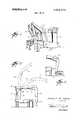
- FIG. 1is a side view, in perspective, of the device with the arms in retracted position.
- FIG. 2is a rear view of the device, showing the arms in another position, and illustrating the movement of the arms in dotted lines.
- FIG. 3is a side elevational view of the device illustrating the arm actuation means employed.
- FIG. 4is an enlarged front view of one form of arm head, showing the winches employed in dotted line.
- FIG. 5is a fragmentary view of a fork mounted on the end of the arms.
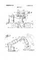
- FIG. 6is a side elevation view of a modified form of device showing the engine location below the loading bed.
- FIG. 7is an elevation view of one of the modified arms having both extensible gantry and boom.
- FIG. 8is a plan view illustrating the pickup of a load and the movement of the cab so that the operator can face forward during movement of the device and the load during lifting operations.
- FIG. 9is a side view of the extensible gantry.
- FIG. 10is a sectional view of the roller support for movement of the telescoping sections of the gantry taken along line 10-10 in FIG. 9.
- the numeral 1designates a flat bed vehicle body having the cab 2 housing the motor and controls (not shown) and having the fixed boom supports 3, 3.
- a pair of main boom members 4, 4are pivotally mounted on the supports 3, 3 and the gantry members 5, 5 are pivotally mounted on the extended ends of said members 4, 4, forming the gantry boom.
- Supporting members 6, 6maintain the main boom members in horizontal alignment, and hydraulic rams as 7, 7 adjacent each support member 3, 3, and the hydraulic ram 8 mounted on the vehicle bed between the boom members 4, 4, have the extended ends of their ram piston arms mounted on the transverse supporting shaft 9.
- the shaft 9is in the ends of the boom members 4, 4, rearwardly of the fulcrum point 10, 10 of the main boom members 4, 4 in the supports 3, 3.
- Hydraulic rams ll, 11are mounted on the inside walls of the boom members 4, 4 and the extended ends of the pistons of said rams 11, 11 are pivotally anchored to the gantry members 5, 5.
- the extended ends of the gantry members 5, 5form the head of the gantry, having the hydraulically operated winches 12, 12 which actuate the cat heads l3, 13.
- a pair of hydraulic ramsact as stabilizers l4, l4 and are mounted on the vehicle bed 1, on the side opposite the supports 3, 3.
- the controls in the cabpermit the loading arms to be employed in loading pipe, steel beams, lumber and the like from the side, the jointed structure permitting picking up a load from a stack, barge or car, or the like, and placing same on the truck in the desired location, the cat heads, with the usual line 15 and hook 16 being employed in the usual manner, and said winches 12, 12 being operable independently or together.
- the loadmay be taken from or deposited on stacks below or above the level of the truck bed, the dual arms providing adequate power as well as control of the load being lifted.
- a fork 17is attached to the arm 18, in lieu of the catheads. With the arm being jointed, the load may be lifted from any location and maintained level as it is loaded on the vehicle 19.
- FIGS. 6 through 10A modified form of side-loading truck is shown in FIGS. 6 through 10.
- Such truckhas a bed 20 suitably supported on wheels with an engine mounted in the housing 21 centrally beneath the bed 20, a cab 22 and loading means mounted to one side of the bed 20.
- the lifting meansincludes a rotary table support 23, with jointed arms 24 tied together by the traces 25 pivotally mounted on support 23 and the winches 26 in the heads on arms 24. Any suitable load engaging means may be used and in the modified form shown magnets 27 are supported on the cables 28 from the winches.
- the bed 20has the stabilizing rams 29 on the side of the bed away from cab 22 and support 23 similar to the stabilizers 14 previously described.
- the hydraulic rams 30engage the transverse supporting shafts 31 to control the pivoting of the main boom members 32 with respect to the support 23.
- the hydraulic rams 33control the pivoting of the gantry members 34 with respect to the main boom members 32.
- the arms 24are similar to the arms 4, 5 except that both the main boom members 32 and the gantry members 34 are extensible. By constructing such members of telescoping structural members and means for extending and retracting the structural members, the flexibility of the loading means is substantially extended.
- Such structureallows loading from and unloading to positions higher, lower and farther from the truck than would be possible with short fixed arms but retains the advantage of minimizing the extention of the arms out from the truck when the arms are in fully retracted posltlon.
- a gantry member 34is shown composed of end members 35 and 36 with telescoping structural means 37 extending between the end members and the ram 38 extending between the end members 35 and 36 and through the structural means 37.
- the telescoping structural means 37includes the outer box member 39, the inner channel 40 and the means slidably supporting the channel 40 within the box 39.
- Such support meansincludes the rollers 41 which engage the corners of channel 40 and the rollers 42 which engage the ends of the legs of the channel 40.
- Each of the rollers 41 and 42are rotatively mounted on pins which are supported by portions of the box 39 on both sides of the rollers.
- FIG. which clearly illustrates the roller support of the telescoping meansis a typical section, there being a plurality of such roller stations to assure sufficient strength for supporting all loads imposed thereon.
- the cab 22 as best shown in FIG. 8is pivotally mounted on the bed so that the operator can face in the direction of movement when driving the truck and can face the load during loading and unloading of the truck.
- This pivoting of the cab to allow the operator to see what he is doing without difficultygreatly improves the safety of the improved side-loading truck of the present invention.
- support 23is a rotary table type of support the pivoting of cab 22 is especially desirable to give the operator a clear view of the am 24 particularly when they have been rotated to a position other than extending across the bed 20.
- a side-loading transporting devicecomprising a bed suitably supported on wheels,
- each of said loading armsincluding a main boom member and a gantry member
- main boom memberseach having telescoping structural members and means for extending and retracting said main boom structural members
- said gantry memberseach having telescoping structural members and means for extending and retracting said gantry structural members.
- a side-loading transporting devicewherein said main boom and gantry structural members each include a pair of end members,
- said extending and retracting meansextending axially through said telescoping structural means.
- a side-loading transporting deviceaccording to claim 2 wherein said telescoping structural means includes an outer box member,
- a side-loading transporting deviceincludes a first set of rollers rotatably mounted in said outer box member and adapted to have rolling engagement with the corners of said channel member, and
- a second set of rollersrotatably mounted in said outer box member and adapted to have rolling engagement with the pads of the legs of said channel member.
- a side-loading transporting devicecomprising a bed suitably supported on wheels,
- a housing for said enginepositioned beneath the central portion of said bed
- each of said loading armsincluding a main boom member
- a cab on said bedcontaining the controls for moving said device and said loading arms
- said cabbeing positioned on the same side of said bed on which said support means is positioned, said extending and retracting means including an outer box member, an inner channel member, means for slidably supporting said channel member within said box member, and a ram consecond set of rollers rotatably mounted in said outer box member and adapted to have rolling engagement with the ends of the legs of said channel member.
Landscapes
- Engineering & Computer Science (AREA)
- Mechanical Engineering (AREA)
- Transportation (AREA)
- Jib Cranes (AREA)
- Forklifts And Lifting Vehicles (AREA)
Abstract
Description
Claims (5)
Applications Claiming Priority (1)
| Application Number | Priority Date | Filing Date | Title |
|---|---|---|---|
| US4121570A | 1970-05-28 | 1970-05-28 |
Publications (1)
| Publication Number | Publication Date |
|---|---|
| US3685673Atrue US3685673A (en) | 1972-08-22 |
Family
ID=21915360
Family Applications (1)
| Application Number | Title | Priority Date | Filing Date |
|---|---|---|---|
| US41215AExpired - LifetimeUS3685673A (en) | 1970-05-28 | 1970-05-28 | Side-loading self-propelled material transporting device |
Country Status (5)
| Country | Link |
|---|---|
| US (1) | US3685673A (en) |
| JP (1) | JPS49586B1 (en) |
| DE (1) | DE2108323A1 (en) |
| FR (1) | FR2092315A5 (en) |
| GB (1) | GB1288327A (en) |
Cited By (21)
| Publication number | Priority date | Publication date | Assignee | Title |
|---|---|---|---|---|
| US3905498A (en)* | 1970-08-13 | 1975-09-16 | Lely Cornelis V D | Wagons having loading and unloading equipment |
| US3950914A (en)* | 1973-09-20 | 1976-04-20 | John Laing & Son Limited | Building elements |
| US4227849A (en)* | 1978-05-24 | 1980-10-14 | Wayne H. Worthington | Refuse collection device |
| US4575305A (en)* | 1983-11-18 | 1986-03-11 | Bon Ton Rolle Limited | Truck mounted tube bundle pulling apparatus |
| US4666365A (en)* | 1983-11-18 | 1987-05-19 | Bon Ton Rolle Limited | Tube bundle pulling apparatus |
| US4818172A (en)* | 1987-08-25 | 1989-04-04 | Harsco Corporation | Parasitic crane |
| US4921394A (en)* | 1987-07-24 | 1990-05-01 | Eka Limited | Load handling device |
| DE3937622A1 (en)* | 1989-11-09 | 1991-05-16 | Loesch & Reinberger Gmbh | Transporter vehicle hoist for raising and lowering lifting equipment - has boom pivoting, about longitudinal axis, between position centrally behind cabin, and position at vehicle side |
| EP0913295A1 (en) | 1997-10-31 | 1999-05-06 | Ludwig Bauch | Vehicle for taking up and transporting of loads |
| US5931321A (en)* | 1998-03-31 | 1999-08-03 | Grant; Robert K. | Crane mechanism |
| WO1999042323A1 (en)* | 1998-02-23 | 1999-08-26 | Oy Meclift Ltd. | Transfer machine |
| US6183185B1 (en)* | 1994-07-07 | 2001-02-06 | Heil Co. | Loader assembly for an articulated refuse collection vehicle |
| WO2006003385A1 (en)* | 2004-06-30 | 2006-01-12 | Glide-Rite Products Ltd | Load handling device |
| US20100276227A1 (en)* | 2007-03-19 | 2010-11-04 | Patriot3, Inc. | Tactical vehicle with line deployment tower |
| WO2011006420A1 (en)* | 2009-07-14 | 2011-01-20 | 湖南三一智能控制设备有限公司 | Mobile crane and manufacturing method for mobile crane |
| CN102128310A (en)* | 2010-12-22 | 2011-07-20 | 中国石油天然气集团公司 | Tunnel pipe distributing machine |
| US20110182706A1 (en)* | 2010-01-22 | 2011-07-28 | Marola Martin A | Heavy Duty Vehicle Recovery System |
| CN111791785A (en)* | 2020-08-06 | 2020-10-20 | 山河智能装备股份有限公司 | Self-loading and self-unloading transport vehicle and bilateral suspension device |
| US20220008965A1 (en)* | 2020-07-07 | 2022-01-13 | James A. McLeod | Clearing Device for Removal of Snow or Ice from a Pipe |
| US20230337572A1 (en)* | 2022-04-20 | 2023-10-26 | Samuel S Brandenberger | Self-Loading Manure Spreader |
| US20240009580A1 (en)* | 2022-07-07 | 2024-01-11 | Diggerland USA, LLC | Amusement Activity Station |
Families Citing this family (7)
| Publication number | Priority date | Publication date | Assignee | Title |
|---|---|---|---|---|
| FR2435684A1 (en)* | 1978-09-05 | 1980-04-04 | Creusot Loire | Charging device for steel melting plant - where travelling semi-portal carries charging basket through sound-proof enclosure to arc furnace |
| DE3174352D1 (en)* | 1981-11-23 | 1986-05-15 | O R M I G S P A | Mobile yard crane for the handling of containers |
| DE3212583A1 (en)* | 1982-04-03 | 1983-10-13 | Braunschweigische Maschinenbauanstalt AG, 3300 Braunschweig | TRANSPORT VEHICLE FOR CONTAINER HANDLING, ESPECIALLY AIRPLANES |
| GB8630043D0 (en)* | 1986-12-16 | 1987-01-28 | Shepherd R J | Vehicles |
| DE19603966A1 (en)* | 1996-01-26 | 1997-07-31 | Kirow Leipzig Rail & Port Ag M | Mobile crane |
| RU2150394C1 (en)* | 1999-01-25 | 2000-06-10 | Салдаев Александр Макарович | Device for loading bales of pressed up medicinal herbs into large-, medium-, and small-sized containers |
| CN116281679B (en)* | 2023-05-18 | 2023-10-03 | 四川川运重工机械有限公司 | Lorry-mounted crane and stretching system thereof |
Citations (11)
| Publication number | Priority date | Publication date | Assignee | Title |
|---|---|---|---|---|
| GB899484A (en)* | 1960-11-14 | 1962-06-20 | Peter Moskopf | Vehicle for gripping, stacking and transporting building elements and other objects |
| US3095099A (en)* | 1961-02-08 | 1963-06-25 | Daniel R Costello | Self-loading flat-bed truck |
| US3187905A (en)* | 1963-01-11 | 1965-06-08 | Moskopf Peter Franziskus | Jibs |
| GB1027451A (en)* | 1961-02-07 | 1966-04-27 | Warren Hugh Payne | Improvements in boom type truckloaders |
| US3265219A (en)* | 1964-10-27 | 1966-08-09 | Hydrauliska Ind Aktiebolaget | Crane with folding boom which passes close to but clears its mast |
| US3305118A (en)* | 1966-01-19 | 1967-02-21 | Le Grand H Lull | Load handling carriage |
| US3404792A (en)* | 1965-10-08 | 1968-10-08 | Hiab Hydraulics Corp | Material handling device |
| US3452888A (en)* | 1967-08-04 | 1969-07-01 | Beloit Corp | Apparatus for lifting and forwarding tree-length logs |
| US3472405A (en)* | 1968-08-26 | 1969-10-14 | Koehring Co | Material handling apparatus |
| US3481490A (en)* | 1966-06-30 | 1969-12-02 | Gottwald Kg Leo | Telescopic jib for jib cranes |
| US3487964A (en)* | 1968-01-24 | 1970-01-06 | Joseph L Riley | Self-loading side loaders |
- 1970
- 1970-05-28USUS41215Apatent/US3685673A/ennot_activeExpired - Lifetime
- 1970-08-24GBGB4069870Apatent/GB1288327A/ennot_activeExpired
- 1970-10-05JPJP45086724Apatent/JPS49586B1/jaactivePending
- 1970-12-29FRFR7046991Apatent/FR2092315A5/frnot_activeExpired
- 1971
- 1971-02-22DEDE19712108323patent/DE2108323A1/enactivePending
Patent Citations (11)
| Publication number | Priority date | Publication date | Assignee | Title |
|---|---|---|---|---|
| GB899484A (en)* | 1960-11-14 | 1962-06-20 | Peter Moskopf | Vehicle for gripping, stacking and transporting building elements and other objects |
| GB1027451A (en)* | 1961-02-07 | 1966-04-27 | Warren Hugh Payne | Improvements in boom type truckloaders |
| US3095099A (en)* | 1961-02-08 | 1963-06-25 | Daniel R Costello | Self-loading flat-bed truck |
| US3187905A (en)* | 1963-01-11 | 1965-06-08 | Moskopf Peter Franziskus | Jibs |
| US3265219A (en)* | 1964-10-27 | 1966-08-09 | Hydrauliska Ind Aktiebolaget | Crane with folding boom which passes close to but clears its mast |
| US3404792A (en)* | 1965-10-08 | 1968-10-08 | Hiab Hydraulics Corp | Material handling device |
| US3305118A (en)* | 1966-01-19 | 1967-02-21 | Le Grand H Lull | Load handling carriage |
| US3481490A (en)* | 1966-06-30 | 1969-12-02 | Gottwald Kg Leo | Telescopic jib for jib cranes |
| US3452888A (en)* | 1967-08-04 | 1969-07-01 | Beloit Corp | Apparatus for lifting and forwarding tree-length logs |
| US3487964A (en)* | 1968-01-24 | 1970-01-06 | Joseph L Riley | Self-loading side loaders |
| US3472405A (en)* | 1968-08-26 | 1969-10-14 | Koehring Co | Material handling apparatus |
Cited By (27)
| Publication number | Priority date | Publication date | Assignee | Title |
|---|---|---|---|---|
| US3905498A (en)* | 1970-08-13 | 1975-09-16 | Lely Cornelis V D | Wagons having loading and unloading equipment |
| US3950914A (en)* | 1973-09-20 | 1976-04-20 | John Laing & Son Limited | Building elements |
| US4227849A (en)* | 1978-05-24 | 1980-10-14 | Wayne H. Worthington | Refuse collection device |
| US4575305A (en)* | 1983-11-18 | 1986-03-11 | Bon Ton Rolle Limited | Truck mounted tube bundle pulling apparatus |
| US4666365A (en)* | 1983-11-18 | 1987-05-19 | Bon Ton Rolle Limited | Tube bundle pulling apparatus |
| US4921394A (en)* | 1987-07-24 | 1990-05-01 | Eka Limited | Load handling device |
| US4818172A (en)* | 1987-08-25 | 1989-04-04 | Harsco Corporation | Parasitic crane |
| DE3937622A1 (en)* | 1989-11-09 | 1991-05-16 | Loesch & Reinberger Gmbh | Transporter vehicle hoist for raising and lowering lifting equipment - has boom pivoting, about longitudinal axis, between position centrally behind cabin, and position at vehicle side |
| US6183185B1 (en)* | 1994-07-07 | 2001-02-06 | Heil Co. | Loader assembly for an articulated refuse collection vehicle |
| DE19748313C2 (en)* | 1997-10-31 | 2001-01-25 | Ludwig Bauch | Vehicle for lifting and transporting loads |
| EP0913295A1 (en) | 1997-10-31 | 1999-05-06 | Ludwig Bauch | Vehicle for taking up and transporting of loads |
| WO1999042323A1 (en)* | 1998-02-23 | 1999-08-26 | Oy Meclift Ltd. | Transfer machine |
| US6565307B1 (en) | 1998-02-23 | 2003-05-20 | Oy Meclift Ltd. | Transfer machine |
| US5931321A (en)* | 1998-03-31 | 1999-08-03 | Grant; Robert K. | Crane mechanism |
| WO2006003385A1 (en)* | 2004-06-30 | 2006-01-12 | Glide-Rite Products Ltd | Load handling device |
| US8813911B2 (en)* | 2007-03-19 | 2014-08-26 | Patriot3, Inc. | Tactical vehicle with line deployment tower |
| US20100276227A1 (en)* | 2007-03-19 | 2010-11-04 | Patriot3, Inc. | Tactical vehicle with line deployment tower |
| WO2011006420A1 (en)* | 2009-07-14 | 2011-01-20 | 湖南三一智能控制设备有限公司 | Mobile crane and manufacturing method for mobile crane |
| US20110182706A1 (en)* | 2010-01-22 | 2011-07-28 | Marola Martin A | Heavy Duty Vehicle Recovery System |
| US8690514B2 (en)* | 2010-01-22 | 2014-04-08 | Martin A. Marola | Heavy duty vehicle recovery system |
| CN102128310A (en)* | 2010-12-22 | 2011-07-20 | 中国石油天然气集团公司 | Tunnel pipe distributing machine |
| US20220008965A1 (en)* | 2020-07-07 | 2022-01-13 | James A. McLeod | Clearing Device for Removal of Snow or Ice from a Pipe |
| US11826797B2 (en)* | 2020-07-07 | 2023-11-28 | James A. McLeod | Clearing device for removal of snow or ice from a pipe |
| CN111791785A (en)* | 2020-08-06 | 2020-10-20 | 山河智能装备股份有限公司 | Self-loading and self-unloading transport vehicle and bilateral suspension device |
| CN111791785B (en)* | 2020-08-06 | 2024-10-18 | 山河智能特种装备有限公司 | Self-loading and unloading transport vehicle and double-side suspension device |
| US20230337572A1 (en)* | 2022-04-20 | 2023-10-26 | Samuel S Brandenberger | Self-Loading Manure Spreader |
| US20240009580A1 (en)* | 2022-07-07 | 2024-01-11 | Diggerland USA, LLC | Amusement Activity Station |
Also Published As
| Publication number | Publication date |
|---|---|
| JPS49586B1 (en) | 1974-01-08 |
| DE2108323A1 (en) | 1972-03-02 |
| FR2092315A5 (en) | 1971-01-21 |
| GB1288327A (en) | 1972-09-06 |
Similar Documents
| Publication | Publication Date | Title |
|---|---|---|
| US3685673A (en) | Side-loading self-propelled material transporting device | |
| US3747789A (en) | Load handling vehicle | |
| USRE30021E (en) | Material handling machine | |
| US3784035A (en) | Vehicle mounted loading hoist | |
| US3490622A (en) | Van handler vehicle | |
| US4024968A (en) | Heavy lift side loader truck | |
| US3889818A (en) | Extensible crane | |
| ES445299A1 (en) | EXTENDABLE LIFTING AND DISPLACING MECHANISM FOR FORKLIFT OR SIMILAR VEHICLE. | |
| US3762588A (en) | Front and lateral loading mechanism | |
| US3606053A (en) | Grappler-spreader for cantilever-boom trucks | |
| US3281119A (en) | Fork lift with forward reach | |
| US3613918A (en) | Field service vehicle | |
| US3154025A (en) | Load handling equipment | |
| US3468439A (en) | Device for handling lengthy loads,mainly insulation-coated pipes,transported by truck trains | |
| USRE27905E (en) | Certificate of correction | |
| US3216588A (en) | Loading apparatus | |
| CN111688564B (en) | Self-discharging loading vehicle | |
| US3874528A (en) | Vehicle mounted loader for handling concrete castings | |
| US3785515A (en) | Transverse-traveling load handling vehicle | |
| US3684114A (en) | Fork lift load handling devices | |
| US2708044A (en) | Tractor trailer carrier | |
| CN216342305U (en) | Telescopic arm type carrier | |
| US5931321A (en) | Crane mechanism | |
| US2750060A (en) | Sling attachment for industrial lift trucks | |
| GB1417126A (en) | Lift trucks |
Legal Events
| Date | Code | Title | Description |
|---|---|---|---|
| AS | Assignment | Owner name:CRC PIPELINE INTERNATIONAL, INC., 3200 FIRST CITY Free format text:ASSIGNMENT OF ASSIGNORS INTEREST.;ASSIGNOR:CRUTCHER RESOURCES CORPORATION, A CORP OF DE;REEL/FRAME:004372/0261 Effective date:19850228 | |
| AS | Assignment | Owner name:BANKERS TRUST COMPANY, 280 PARK AVENUE, NEW YORK, Free format text:SECURITY INTEREST;ASSIGNOR:CRC-EVANS PIPELINE INTERNATIONAL, INC., A TX. CORP.;REEL/FRAME:004568/0503 Effective date:19860314 Owner name:MELLON BANK, N.A., ONE MELLON BANK CENTER, PITTSBU Free format text:SECURITY INTEREST;ASSIGNOR:CRC-EVANS PIPELINE INTERNATIONAL, INC., A TX. CORP.;REEL/FRAME:004568/0503 Effective date:19860314 | |
| AS | Assignment | Owner name:CRC-EVANS PIPELINE INTERNATIONAL, INC., A CORP. OF Free format text:ASSIGNMENT OF ASSIGNORS INTEREST.;ASSIGNOR:CRC-EVANS PIPELINE INTERNATIONAL, INC.;REEL/FRAME:005003/0669 Effective date:19880705 | |
| AS | Assignment | Owner name:WELLS FARGO BANK, N.A., A NATIONAL BANKING ASSOCIA Free format text:SECURITY INTEREST;ASSIGNOR:ENTERRA CORPORATION;REEL/FRAME:005012/0795 Effective date:19880324 Owner name:WELLS FARGO BANK, N.A., A NATIONAL BANKING ASSOC. Free format text:SECURITY INTEREST;ASSIGNOR:CRC-EVANS PIPELINE INTERNATIONAL, INC.;REEL/FRAME:005010/0529 Effective date:19880324 Owner name:ENTERRA CORPORATION, TEXAS Free format text:SECURITY INTEREST;ASSIGNOR:CONNECT CORPORATION, A DE CORP. (WHICH UPON ITS MERGER WITH CRC-EVANS PIPELINE INTERNATIONAL, INC., A TX CORP., SHALL CHANGE ITS NAME TO CRC -EVANS PIPELINE INTERNATIONAL, INC., A DE CORP.);REEL/FRAME:005041/0151 Effective date:19880324 |