US3650042A - Gas barrier for interconnecting and isolating two atmospheres - Google Patents
Gas barrier for interconnecting and isolating two atmospheresDownload PDFInfo
- Publication number
- US3650042A US3650042AUS825777AUS3650042DAUS3650042AUS 3650042 AUS3650042 AUS 3650042AUS 825777 AUS825777 AUS 825777AUS 3650042D AUS3650042D AUS 3650042DAUS 3650042 AUS3650042 AUS 3650042A
- Authority
- US
- United States
- Prior art keywords
- pressure
- compartments
- tier
- reactive
- inlet
- Prior art date
- Legal status (The legal status is an assumption and is not a legal conclusion. Google has not performed a legal analysis and makes no representation as to the accuracy of the status listed.)
- Expired - Lifetime
Links
- 230000004888barrier functionEffects0.000titledescription2
- 230000000295complement effectEffects0.000claimsabstractdescription34
- 238000002955isolationMethods0.000claimsabstractdescription32
- 230000007704transitionEffects0.000claimsabstractdescription14
- 239000007789gasSubstances0.000claims25
- 239000000758substrateSubstances0.000claims24
- 239000000969carrierSubstances0.000claims15
- 239000004065semiconductorSubstances0.000claims11
- 241000269627Amphiuma meansSpecies0.000claims2
- 238000005192partitionMethods0.000claims2
- 238000013508migrationMethods0.000abstractdescription2
Images


Classifications
- H—ELECTRICITY
- H01—ELECTRIC ELEMENTS
- H01L—SEMICONDUCTOR DEVICES NOT COVERED BY CLASS H10
- H01L21/00—Processes or apparatus adapted for the manufacture or treatment of semiconductor or solid state devices or of parts thereof
- H01L21/67—Apparatus specially adapted for handling semiconductor or electric solid state devices during manufacture or treatment thereof; Apparatus specially adapted for handling wafers during manufacture or treatment of semiconductor or electric solid state devices or components ; Apparatus not specifically provided for elsewhere
- H01L21/67005—Apparatus not specifically provided for elsewhere
- H01L21/67011—Apparatus for manufacture or treatment
- H01L21/67155—Apparatus for manufacturing or treating in a plurality of work-stations
- H01L21/67161—Apparatus for manufacturing or treating in a plurality of work-stations characterized by the layout of the process chambers
- H01L21/67173—Apparatus for manufacturing or treating in a plurality of work-stations characterized by the layout of the process chambers in-line arrangement
- C—CHEMISTRY; METALLURGY
- C23—COATING METALLIC MATERIAL; COATING MATERIAL WITH METALLIC MATERIAL; CHEMICAL SURFACE TREATMENT; DIFFUSION TREATMENT OF METALLIC MATERIAL; COATING BY VACUUM EVAPORATION, BY SPUTTERING, BY ION IMPLANTATION OR BY CHEMICAL VAPOUR DEPOSITION, IN GENERAL; INHIBITING CORROSION OF METALLIC MATERIAL OR INCRUSTATION IN GENERAL
- C23C—COATING METALLIC MATERIAL; COATING MATERIAL WITH METALLIC MATERIAL; SURFACE TREATMENT OF METALLIC MATERIAL BY DIFFUSION INTO THE SURFACE, BY CHEMICAL CONVERSION OR SUBSTITUTION; COATING BY VACUUM EVAPORATION, BY SPUTTERING, BY ION IMPLANTATION OR BY CHEMICAL VAPOUR DEPOSITION, IN GENERAL
- C23C14/00—Coating by vacuum evaporation, by sputtering or by ion implantation of the coating forming material
- C23C14/22—Coating by vacuum evaporation, by sputtering or by ion implantation of the coating forming material characterised by the process of coating
- C23C14/56—Apparatus specially adapted for continuous coating; Arrangements for maintaining the vacuum, e.g. vacuum locks
- C—CHEMISTRY; METALLURGY
- C23—COATING METALLIC MATERIAL; COATING MATERIAL WITH METALLIC MATERIAL; CHEMICAL SURFACE TREATMENT; DIFFUSION TREATMENT OF METALLIC MATERIAL; COATING BY VACUUM EVAPORATION, BY SPUTTERING, BY ION IMPLANTATION OR BY CHEMICAL VAPOUR DEPOSITION, IN GENERAL; INHIBITING CORROSION OF METALLIC MATERIAL OR INCRUSTATION IN GENERAL
- C23C—COATING METALLIC MATERIAL; COATING MATERIAL WITH METALLIC MATERIAL; SURFACE TREATMENT OF METALLIC MATERIAL BY DIFFUSION INTO THE SURFACE, BY CHEMICAL CONVERSION OR SUBSTITUTION; COATING BY VACUUM EVAPORATION, BY SPUTTERING, BY ION IMPLANTATION OR BY CHEMICAL VAPOUR DEPOSITION, IN GENERAL
- C23C16/00—Chemical coating by decomposition of gaseous compounds, without leaving reaction products of surface material in the coating, i.e. chemical vapour deposition [CVD] processes
- C23C16/44—Chemical coating by decomposition of gaseous compounds, without leaving reaction products of surface material in the coating, i.e. chemical vapour deposition [CVD] processes characterised by the method of coating
- C23C16/54—Apparatus specially adapted for continuous coating
- C—CHEMISTRY; METALLURGY
- C23—COATING METALLIC MATERIAL; COATING MATERIAL WITH METALLIC MATERIAL; CHEMICAL SURFACE TREATMENT; DIFFUSION TREATMENT OF METALLIC MATERIAL; COATING BY VACUUM EVAPORATION, BY SPUTTERING, BY ION IMPLANTATION OR BY CHEMICAL VAPOUR DEPOSITION, IN GENERAL; INHIBITING CORROSION OF METALLIC MATERIAL OR INCRUSTATION IN GENERAL
- C23F—NON-MECHANICAL REMOVAL OF METALLIC MATERIAL FROM SURFACE; INHIBITING CORROSION OF METALLIC MATERIAL OR INCRUSTATION IN GENERAL; MULTI-STEP PROCESSES FOR SURFACE TREATMENT OF METALLIC MATERIAL INVOLVING AT LEAST ONE PROCESS PROVIDED FOR IN CLASS C23 AND AT LEAST ONE PROCESS COVERED BY SUBCLASS C21D OR C22F OR CLASS C25
- C23F1/00—Etching metallic material by chemical means
- C—CHEMISTRY; METALLURGY
- C30—CRYSTAL GROWTH
- C30B—SINGLE-CRYSTAL GROWTH; UNIDIRECTIONAL SOLIDIFICATION OF EUTECTIC MATERIAL OR UNIDIRECTIONAL DEMIXING OF EUTECTOID MATERIAL; REFINING BY ZONE-MELTING OF MATERIAL; PRODUCTION OF A HOMOGENEOUS POLYCRYSTALLINE MATERIAL WITH DEFINED STRUCTURE; SINGLE CRYSTALS OR HOMOGENEOUS POLYCRYSTALLINE MATERIAL WITH DEFINED STRUCTURE; AFTER-TREATMENT OF SINGLE CRYSTALS OR A HOMOGENEOUS POLYCRYSTALLINE MATERIAL WITH DEFINED STRUCTURE; APPARATUS THEREFOR
- C30B31/00—Diffusion or doping processes for single crystals or homogeneous polycrystalline material with defined structure; Apparatus therefor
- C30B31/06—Diffusion or doping processes for single crystals or homogeneous polycrystalline material with defined structure; Apparatus therefor by contacting with diffusion material in the gaseous state
- C30B31/10—Reaction chambers; Selection of materials therefor
- C30B31/106—Continuous processes
- C—CHEMISTRY; METALLURGY
- C30—CRYSTAL GROWTH
- C30B—SINGLE-CRYSTAL GROWTH; UNIDIRECTIONAL SOLIDIFICATION OF EUTECTIC MATERIAL OR UNIDIRECTIONAL DEMIXING OF EUTECTOID MATERIAL; REFINING BY ZONE-MELTING OF MATERIAL; PRODUCTION OF A HOMOGENEOUS POLYCRYSTALLINE MATERIAL WITH DEFINED STRUCTURE; SINGLE CRYSTALS OR HOMOGENEOUS POLYCRYSTALLINE MATERIAL WITH DEFINED STRUCTURE; AFTER-TREATMENT OF SINGLE CRYSTALS OR A HOMOGENEOUS POLYCRYSTALLINE MATERIAL WITH DEFINED STRUCTURE; APPARATUS THEREFOR
- C30B31/00—Diffusion or doping processes for single crystals or homogeneous polycrystalline material with defined structure; Apparatus therefor
- C30B31/06—Diffusion or doping processes for single crystals or homogeneous polycrystalline material with defined structure; Apparatus therefor by contacting with diffusion material in the gaseous state
- C30B31/16—Feed and outlet means for the gases; Modifying the flow of the gases
- H—ELECTRICITY
- H01—ELECTRIC ELEMENTS
- H01L—SEMICONDUCTOR DEVICES NOT COVERED BY CLASS H10
- H01L21/00—Processes or apparatus adapted for the manufacture or treatment of semiconductor or solid state devices or of parts thereof
- H01L21/67—Apparatus specially adapted for handling semiconductor or electric solid state devices during manufacture or treatment thereof; Apparatus specially adapted for handling wafers during manufacture or treatment of semiconductor or electric solid state devices or components ; Apparatus not specifically provided for elsewhere
- H01L21/67005—Apparatus not specifically provided for elsewhere
- H01L21/67011—Apparatus for manufacture or treatment
- H01L21/67098—Apparatus for thermal treatment
- H01L21/67109—Apparatus for thermal treatment mainly by convection
- H—ELECTRICITY
- H01—ELECTRIC ELEMENTS
- H01L—SEMICONDUCTOR DEVICES NOT COVERED BY CLASS H10
- H01L21/00—Processes or apparatus adapted for the manufacture or treatment of semiconductor or solid state devices or of parts thereof
- H01L21/67—Apparatus specially adapted for handling semiconductor or electric solid state devices during manufacture or treatment thereof; Apparatus specially adapted for handling wafers during manufacture or treatment of semiconductor or electric solid state devices or components ; Apparatus not specifically provided for elsewhere
- H01L21/67005—Apparatus not specifically provided for elsewhere
- H01L21/67011—Apparatus for manufacture or treatment
- H01L21/67155—Apparatus for manufacturing or treating in a plurality of work-stations
- H01L21/6719—Apparatus for manufacturing or treating in a plurality of work-stations characterized by the construction of the processing chambers, e.g. modular processing chambers
Definitions
- a transition or isolation zonefor accommodating continuous free flow of a tier of articles between two distinct and isolated atmospheres.
- the transition zoneincludes a series of alternate inlet and outlet compartments for a non-reactive gas wherein the compartments contain inlet and outlet openings interconnecting with each other and the indicated atmospheres.
- the cross sections of the openingsare complementary to the cross section of the tier of articles to provide a restricted orifice-size clearance therebetween, whereby the orifice phenomena can be employed by correlation of pressures to control the flow of gas and conversely to substantially completely isolate the indicated atmospheres without any measurable cross-migration therebetween.
Landscapes
- Chemical & Material Sciences (AREA)
- Engineering & Computer Science (AREA)
- Organic Chemistry (AREA)
- Materials Engineering (AREA)
- Metallurgy (AREA)
- General Physics & Mathematics (AREA)
- Physics & Mathematics (AREA)
- Condensed Matter Physics & Semiconductors (AREA)
- Manufacturing & Machinery (AREA)
- Computer Hardware Design (AREA)
- Microelectronics & Electronic Packaging (AREA)
- Power Engineering (AREA)
- Chemical Kinetics & Catalysis (AREA)
- Mechanical Engineering (AREA)
- Crystallography & Structural Chemistry (AREA)
- General Chemical & Material Sciences (AREA)
- Chemical Vapour Deposition (AREA)
Abstract
Description
United States Patent Boerger et al. 5] Mar. 21, 1972 54] GAS BARRIER FOR 2,963,001 12/1960 Alexander ..34 242 x INTERCONNECTING AND ISOLATING 3,067,602 l2/ 1962 Brunt ..68/5 E woS E S 1 3,349,578 10/1967 Greer ..34/242 X [72] Inventors: Frank E. Boerger; William H. White, both Primary Examiner-Edward J. Michael of Poughkeepsie, NY. Attorney-Hanifin and Jancin and Henry Powers [73] Assignee: International Business Machines Corpora- ABSTRACT tion, Armonk, NY.
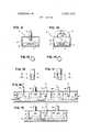
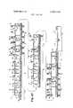
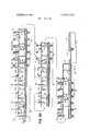
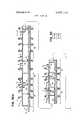
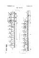
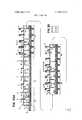
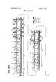
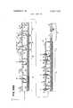
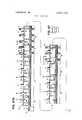
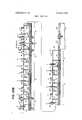
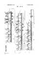
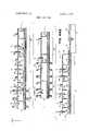
A transition or isolation zone for accommodating continuous free flow of a tier of articles between two distinct and isolated atmospheres. The transition zone includes a series of alternate inlet and outlet compartments for a non-reactive gas wherein the compartments contain inlet and outlet openings interconnecting with each other and the indicated atmospheres. The cross sections of the openings are complementary to the cross section of the tier of articles to provide a restricted orifice-size clearance therebetween, whereby the orifice phenomena can be employed by correlation of pressures to control the flow of gas and conversely to substantially completely isolate the indicated atmospheres without any measurable cross-migration therebetween.
38 Claims, 71 Drawing Figures SHEET 01UF46 PATENTEUHARZI I972 INVENTORS FRANK E. BOERGER WILLIAM H. mm
ATTORNEY FIG.2
PATENTEnMARm I972 SHEET 1UUF46 PAIENTEDMAR21 I972 SHEET 110F416 s l. :T 3T f m 3a a 5 NNdE NZ a 32221: a
PATENTEUHAREI I972 SHEET 120F 46 n. r I I! PATENTEDHARZI I972 SHEET 130F 16 PATENTEBMARZI I972 SHEET 1ROF46 SHEET 150F 56 g a m PATENTEDMAR 21 I972 PATENTEUHARZI I972 SHEET 190F 46 w g ..l 5 o: M m g
Claims (39)
1. In a system for continuous processing of a work throughput transported in a substantially continuous tier therethrough between two isolated atmospheres: a transition zone for interconnecting said two isolated atmospheres having a substantially constant composition comprising A. a series of alternate inlet and outlet compartments having openings for a. non-contact passage of said workpieces therethrough, b. having a cross section substantially complementary to the cross section of said workpieces to define a restricted orifice-size clearance therebetween; and c. said series comprising a minimum of three said compartments; B. inlet means adapted for providing a non-reactive gas in said inlet compartments at a pressure at least as high as the pressures of said atmospheres and having progressively increased pressures form opposite ends of said transition zone toward the interior thereof; C. outlet means adapted for exhausting gases from said outlet compartments; and D. means for transporting said workpieces in said tier from one of said atmospheres through said compartments to the other of said atmospheres.
2. The system of claim 1 wherein the openings between each of adjacent compartments is progressively increased from the opposite end of said transition zone toward the interior thereof while maintaining orifice-size clearance with said workpieces.
2. a positive flow from P6 to P7. said isolation
3. The system of claim 1 wherein the openings to the ones of said compartments at opposite ends of said transition zone adjacent corresponding ones of said atmospheres comprise an extended passageway defining said opening having said complementary cross section.
4. The system of claim 3 wherein the openings between each of adjacent compartments is progressively increased from opposite ends of said transition zone toward the interior thereof while maintaining orifice-size clearance with said workpieces.
5. The system of claim 1 wherein said transition zone comprises three of said compartments defining two of said outlet compartments and one of said inlet compartments with said outlet compartments disposed adjacent corresponding ones of said atmospheres and with the remaining third compartment A. defining a said inlet compartment, disposed intermediate said outlet compartments; and B. provided with said non-reactive gas therein at a pressure substantially greater than the pressures of said atmospheres, with said pressures in said outlet compartments being substantially lower than the pressures of said atmosphere and the pressure in said third compartment.
6. The system of claim 5 including A. means to provide the pressures of said atmospheres at a level which do not exceed about 0.1 p.s.i.g.; and B. wherein said inlet means provides the pressure in said inlet compartment in the range of about 0.004 p.s.i.g. to 0.1 p.s.i.g.
7. The system of claim 1 where said transition zone comprises five compartments defining two of said outlet compartments and three of said inlet compartments with two of said inlet compartments disposed at opposite ends of said transition zone adjacent corresponding ones of said atmospheres, with A. said inlet means adapted to provide the pressure in said two inlet compartments at least equal to the pressures of adjacent ones of said atmospheres; B. the inlet means of the third of said inlet compartments being adapted to maintain the pressure therein at a level substantially greater than the pressures in said two inlet compartments; and C. the said outlet means adapted to maintain the pressure in said outlet compartments substantially lower than the pressures in adjacent ones of said inlet compartments.
8. The system of claim 7 including A. means adapted to maintain the pressures of said atmospheres at a level which does not exceed about 0.1 p.s.i.g.; B. means adapted to provide the pressure in said two inlet compartments in the range of about 0.001 p.s.i.g. to about 0.5 p.s.i.g.; C. means adapted to provide the pressure in said third inlet compartment in the range of about 0.002 p.s.i.g. to about 0.5 p.s.i.g.; D. means to maintain the pressure in said outlet compartments lower than the pressures of said atmospheres and the pressures in adjacent ones of said inlet compartments.
9. In a system for continuous processing of work throughput transported in a substantially continuous tier therethrough between two atmospheres, A. a transition zone interconnecting two atmospheres and comprising an alternate series of inlet and outlet compartments for a non-reactive gas; with said series comprising a minimum of three said compartments; B. means adapted for providing a non-reactive gas in said inlet compartmeNts at a positive pressure at least as high as said pressures of said atmospheres; C. gas exhaust means for withdrawing gases from said outlet compartments to maintain pressures therein below the said pressures in said inlet compartments and of said atmospheres with said positive pressures being progressively increased from the opposite ends of said transition zone toward the interior thereof; and D. means for non-contact transport of said workpiece in said tier from one of said atmospheres through said compartments to the other of said atmospheres.
10. In a processing system for continuous processing of workpieces transported in a substantial tier therethrough between two isolated distinct atmospheres at a pressure at least as high as ambient pressures and having a substantially constant concentration, an isolation chamber interconnected with said atmospheres and comprising A. spaced end walls defining said chamber and having openings for non-contact transport of said tier of said workpieces therethrough from one of said atmospheres to the other of said atmospheres with said openings having a cross section complementary to the cross section of said tier to form a restricted orifice-size clearance therebetween; B. baffle means in said isolation chamber extending transversely thereof and subdividing said chamber into at least three alternate inlet and outlet zones and defining a series of non-contact openings aligned with the openings defined in said end walls; C. means for providing a non-reactive atmosphere in said inlet zones at a positive pressure; and D. means for withdrawing gases from said outlet zones with a. the pressure in said outlet zone adjacent a said end wall maintained lower than the pressure of an adjacent one of said atmospheres, and b. with the pressure in a said inlet zone adjacent a said inlet wall maintained at a level at least equal to the pressure of an adjacent atmosphere, and c. with the positive pressures progressively increasing from adjacent said opposite end walls toward the interior of said isolation chamber.
11. A reactor for continuous processing of workpieces transported in a substantially continuous tier therethrough comprising an open ended tube with the opposite ends thereof exposed to ambient atmosphere, partitions within said tube extending transversely thereof and defining at least three consecutive chambers comprising A. a first reactive chamber; B. an intermediate isolation chamber, and C. a second reactive chamber with said partitions provided with passageways having a cross section substantially complementary to the cross section of said tier to define a restricted orifice-type non-contact clearance therebetween providing resistance to flow of gases therethrough, and interconnecting said chambers; D. a first gas flow means for providing a flow of a reactive gas a. at a first positive pressure level at least as high as ambient pressures, and b. at a substantially constant concentration in a first of said reaction chambers; E. second gas flow means for providing a flow of a second reactive gas a. at a substantially constant concentration, and b. at a second positive pressure at least as high as ambient pressure in a second of said reactive chambers; F. baffle means in said isolation chamber defining therein at least three compartments comprising alternate inlet and outlet compartments for a non-reactive gas; G. third gas flow means for injecting and withdrawing a non-reactive gas in, respectively, said inlet and outlet compartments to provide a. the gas pressure in a said outlet compartment adjacent a said atmosphere lower than the gas pressure in said inlet compartments and at least equal to both said reactive chambers, and b. the gas pressure in said inlet compartments at a positive pressure greater than the gas pressures in both said reactive chambers with the said pressures progressively Increasing from adjacent ends of said isolation chamber toward the interior thereof.
12. The reactor of claim 11 including flanges on said end walls at the openings therethrough defining an elongated tubular passage having the said complementary cross section defining said restricted orifice-size clearance with said tier of workpieces.
13. The reactor of claim 11 wherein said baffles provide progressively increased clearance diverging from said tier inwardly of said isolation chamber.
14. The reactor of claim 13 including flanges on said end walls at the openings thereof defining an extended tubular passageway having the said complementary cross section defining said restricted orifice-size clearance with said tier of workpieces.
15. The reactor of claim 11 wherein said baffles define three consecutive compartments comprising, sequentially A. a first outlet compartment adjacent said first reactive chamber; B. an intermediate inlet compartment; C. a second outlet compartment adjacent the second said reactive chamber; D. means for introducing a non-reactive atmosphere in said inlet compartments at a pressure greater than the pressures in said first and second reactive chambers; E. means for withdrawing gas from said first and second outlet compartments to maintain pressure therein less than the pressures in said inlet compartment and in said first and second reactive chambers; and F. means for transporting said tier of workpieces from said first reactive chamber through said isolation chamber into said second reactive chamber.
16. The reactor of claim 15 wherein said baffles are provided with progressively increased clearances diverging from said tier inwardly of said isolation chamber.
17. The reactor of claim 16 including flanges on the end walls of said isolation chamber about the openings therein defining an elongated tubular passageway having the said cross section defining said restricted orifice-type clearance with said tier of workpieces.
18. The reactor of claim 11 wherein said workpieces comprise planar substrates and including a plurality of carriers therefor adapted for end-to-end transport in said tier from said first reactive chamber, through said isolation chamber and into said second reactive chamber and having A. complementary end configurations to define said continuous tier; B. a recess for mounting said substrates therein; and C. a cross section complementary to the openings in said end walls and said baffles to define said restricted orifice-size clearance therewith.
19. The reactor of claim 18 wherein said baffles are provided with progressively increased clearances with said tier of workpieces diverging from said tier inwardly of said isolation chamber.
20. The reactor of claim 18 including flanges on said end walls at the openings thereof defining an elongated tubular passageway having the said complementary cross section defining said restricted orifice-size clearance with said carriers.
21. The reactor of claim 20 wherein said baffles are provided with progressively increased clearance with said carriers diverging from said tier inwardly of said isolation chamber.
22. The reactor of claim 18 including means for transporting said carriers in said end-to-end relationship from said first reaction chamber through said isolation chamber into said second reactive chamber.
23. A system for processing a moving tier of workpieces comprising A. a reactive chamber; B. means for maintaining a substantially constant reactive first atmosphere in said chamber; C. means for isolating said chamber from a second atmosphere comprising an isolation chamber having a. a first opening communicating with said reactive chamber and having a cross section complementary to said tier of workpieces to form a non-contact restricted orifice-size clearance therebetween, non-contact b. a second opening communicating with said second atmosPhere with said first and second openings having a cross section corresponding to said tier of workpieces to form a non-contact restricted orifice-size clearance therebetween; D. baffle means in said isolation chamber extending transversely thereof and subdividing said isolation chamber into a series of alternate inlet and outlet compartments for a non-reactive atmosphere with said series comprising a minimum of three said compartments; E. means for providing a non-reactive atmosphere in said inlet compartments at a positive pressure at least equal to the pressure in said reactive chambers; F. means for withdrawing gases from said outlet compartments to maintain pressures therein at a level substantially lower than the pressures in said inlet compartments and and in said reactive chambers; and G. means for moving said tier of workpieces from said first reactive chamber through said isolation chamber into said second reactive chamber.
24. The system of claim 23 wherein said compartments comprise, sequentially, a first outlet compartment adjacent said first reactive chamber, an inlet compartment and a second outlet compartment adjacent the said second atmosphere chamber with the pressure of said non-reactive gas in said inlet compartment maintained at a level substantially greater than the pressure of said first and second atmospheres and with the pressure in said outlet compartments maintained substantially lower than the pressures of adjacent atmospheres.
25. The system of claim 23 wherein said baffle means subdivide said chamber into five compartments comprising, sequentially, A. a first inlet compartment adjacent said first reactive chamber; B. a first outlet compartment; C. a second inlet compartment; D. a second outlet compartment; E. a third inlet compartment adjacent the said second atmosphere; F. means for providing a non-reactive atmosphere in said first and third inlet compartments at a pressure at least equal to the pressure of said first and second atmospheres; G. means for providing a non-reactive atmosphere in said second inlet compartment at a pressure substantially greater than the pressure in said first and third inlet compartments; and H. means for withdrawing gases from said outlet compartments to maintain a pressure therein substantially lower than the pressure in adjacent ones of said inlet compartments.
26. The system of claim 24 wherein adjacent ones of said pressures conform to the generalized orifice equation flow K Square Root Delta P and wherein A. the flow F1 between the first atmosphere at a pressure P1 and the first said adjacent outlet compartment at a pressure P42 2 conforms to the equation F1 K1 Square Root P1-P2 where P1 is selected to maintain a flow selected from the group consisting of a. zero flow between P1 and P2 and b. positive flow from P1 to P2 B. the flow F2 between the first said outlet compartment at said pressure P2 and said inlet compartment at a pressure P3 is greater than said flow F1 and conforms to the equation F2 K2 Square Root P3-P2 where P3 is greater than P2 and selected to maintain a positive flow from P3 to P2 C. the flow F3 between said inlet compartment at its said pressure P3 and the second said outlet compartment at a pressure P4 conforms to the equation F3 K3 Square Root P3-P4 where P4 is less than P3 and selected to maintain a positive flow from P3 to P4 D. the flow F4 between said outlet compartment at a said pressure P4 and said second atmosphere adjaCent thereto at a pressure P5 is less than the said flow F3 and conforms to the equation F4 K4 Square Root P5-P4 where P5 is selected to maintain a flow selected from the group consisting of a. zero flow between P5 and P4 and b. positive flow from P5 to P4.
27. The system of claim 25 wherein adjacent said pressures conform to the generalized orifice equation flow K Square Root Delta P and wherein A. the flow F1 between the first atmosphere at a pressure P1 and the first said inlet compartment adjacent thereto at a pressure P2 conforms to the equation F1 K1 Square Root P2-P1 where P2 is selected to maintain a gas flow selected from the groups consisting of a. zero flow between P2 and P1 and b. positive flow from P2 to P1 B. the flow F2 between the first said inlet compartment at said pressure P2 and the first said outlet adjacent the compartment at a pressure P3 conforms to the equation F2 K2 Square Root P2-P3 where a. F2 is greater than F1 b. P3 is smaller than P2 and c. P3 is selected to maintain positive flow from P2 to P3 C. where the flow F3 between said first outlet compartment at said pressure P3 and the adjacent said second inlet compartment thereto at a pressure P4 conforms to the equation F3 K3 Square Root P4-P3 where a. P4 is greater than P3 and P2 and b. P3 is selected to maintain a positive flow F3 from P4 to P3. D. the flow F4 between the second said inlet compartment at said pressure P4 and the adjacent second said outlet compartment at a pressure P5 conforms to the equation F4 K4 Square Root P4-P5 where P4 is greater than P5 and selected to maintain a positive flow F4 from P4 to P5 E. the flow F5 between the second said outlet compartment at said pressure P5 and the next succeeding third said inlet compartment at a pressure P6 conforms to the orifice equation F5 K5 Square Root P6-P5 where a. P6 is greater than P5 b. P6 is lower than P4 and c. P6 is selected to maintain a positive flow from P6 to P5 and E. the flow F6 between the third said inlet compartment at its said pressure P6 and the adjacent second of said atmosphere at a pressure P7 conforms to the generalized orifice equation F6 K6 Square Root P6-P7 where a. p6 is greater than P7 and b. P6 is selected to maintain said flow F6 selected from the group consisting of
28. The system of claim 23 wherein said workpieces comprise planar semiconductor substrates and including a plurality of carriers therefor adapted for end-to-end non-contact transport in said tier from said first reactive chamber, through said isolation chamber and into said second reactive chamber and having A. complementary end configurations to define said continuous tier; B. a recess for Mounting said substrates therein; and C. a cross section complementary to the openings in said end walls and said baffles to define said restricted orifice-size clearance therewith.
29. The system of claim 25 wherein said workpieces comprise planar semiconductor substrates and including a plurality of carriers therefor adapted for non-contact end-to-end transport in said tier through said isolation chamber between said reactive chamber and said second atmosphere and having A. complementary end configurations to define said continuous tier; B. a recess for mounting said substrates therein; and C. a cross section complementary to the openings in said end walls and said baffles to define said restricted orifice-size clearance therewith.
30. The system of claim 1 wherein said workpieces comprise planar semiconductor substrates and including a plurality of carriers therefor adapted for end-to-end non-contact transport in said tier from said first reactive chamber, through said isolation chamber and into said second reactive chamber and having A. complementary end configurations to define said continuous tier; B. a recess for mounting said substrates therein; and C. a cross section complementary to the openings in said end walls and said baffles to define said restricted orifice-size clearance therewith.
31. The system of claim 4 wherein said workpieces comprise planar semiconductor substrates and including a plurality of carriers therefor adapted for end-to-end non-contact transport in said tier from said first reactive chamber, through said isolation chamber and into said second reactive chamber and having A. complementary end configurations to define said continuous tier; B. a recess for mounting said substrates therein; and C. a cross section complementary to the openings in said end walls and said baffles to define said restricted orifice-size clearance therewith.
32. The system of claim 5 wherein said workpieces comprise planar semiconductor substrates and including a plurality of carriers therefor adapted for end-to-end non-contact transport in said tier from said first reactive chamber, through said isolation chamber and into said second reactive chamber and having A. complementary end configurations to define said continuous tier; B. a recess for mounting said substrates therein; and C. a cross section complementary to the openings in said end walls and said baffles to define said restricted orifice-size clearance therewith.
33. The system of claim 7 wherein said workpieces comprise planar semiconductor substrates and including a plurality of carriers therefor adapted for end-to-end non-contact transport in said tier from said first reactive chamber, through said isolation chamber and into said second reactive chamber and having A. complementary end configurations to define said continuous tier; B. a recess for mounting said substrates therein; and C. a cross section complementary to the openings in said end walls and said baffles to define said restricted orifice-size clearance therewith.
34. The system of claim 9 wherein said workpieces comprise planar semiconductor substrates and including a plurality of carriers therefor adapted for end-to-end non-contact transport in said tier from said first reactive chamber, through said isolation chamber and into said second reactive chamber and having A. complementary end configurations to define said continuous tier; B. a recess for mounting said substrates therein; and C. a cross section complementary to the openings in said end walls and said baffles to define said restricted orifice-size clearance therewith.
35. The system of claim 10 wherein said workpieces comprise planar semiconductor substrates and including a plurality of carriers therefor adapted for end-to-end non-contact transport in said tier from said first reactive chamber, through said isolation chamber and into said Second reactive chamber and having A. complementary end configurations to define said continuous tier; B. a recess for mounting said substrates therein; and C. a cross section complementary to the openings in said end walls and said baffles to define said restricted orifice-size clearance therewith.
36. The system of claim 11 wherein said workpieces comprise planar semiconductor substrates and including a plurality of carriers therefor adapted for end-to-end non-contact transport in said tier from said first reactive chamber, through said isolation chamber and into said second reactive chamber and having A. complementary end configurations to define said continuous tier; B. a recess for mounting said substrates therein; and C. a cross section complementary to the openings in said end walls and said baffles to define said restricted orifice-size clearance therewith.
37. The system of claim 13 wherein said workpieces comprise planar semiconductor substrates and including a plurality of carriers therefor adapted for end-to-end non-contact transport in said tier from said first reactive chamber, through said isolation chamber and into said second reactive chamber and having A. complementary end configurations to define said continuous tier; B. a recess for mounting said substrates therein; and C. a cross section complementary to the openings in said end walls and said baffles to define said restricted orifice-size clearance therewith.
38. The system of claim 15 wherein said workpieces comprise planar semiconductor substrates and including a plurality of carriers therefor adapted end-to-end non-contact transport in said tier from said first reactive chamber, through said isolation chamber and into said second reactive chamber and having A. complementary end configurations define said continuous tier; B. a recess for mounting said substrates therein; and C. a cross section complementary to the openings in said end walls and said baffles to define said restricted orifice-size clearance therewith.
Applications Claiming Priority (1)
| Application Number | Priority Date | Filing Date | Title |
|---|---|---|---|
| US82577769A | 1969-05-19 | 1969-05-19 |
Publications (1)
| Publication Number | Publication Date |
|---|---|
| US3650042Atrue US3650042A (en) | 1972-03-21 |
Family
ID=25244895
Family Applications (1)
| Application Number | Title | Priority Date | Filing Date |
|---|---|---|---|
| US825777AExpired - LifetimeUS3650042A (en) | 1969-05-19 | 1969-05-19 | Gas barrier for interconnecting and isolating two atmospheres |
Country Status (1)
| Country | Link |
|---|---|
| US (1) | US3650042A (en) |
Cited By (37)
| Publication number | Priority date | Publication date | Assignee | Title |
|---|---|---|---|---|
| US4048955A (en)* | 1975-09-02 | 1977-09-20 | Texas Instruments Incorporated | Continuous chemical vapor deposition reactor |
| US4268977A (en)* | 1979-12-03 | 1981-05-26 | Exxon Research & Engineering Company | Sealing apparatus for ovens |
| US4938834A (en)* | 1988-03-23 | 1990-07-03 | Mitsubishi Denki Kabushiki Kaisha | Apparatus for preventing the oxidation of lead frames during bonding |
| US5736199A (en)* | 1996-12-05 | 1998-04-07 | Northeastern University | Gating system for continuous pressure infiltration processes |
| WO2000003422A3 (en)* | 1998-07-13 | 2000-08-03 | Applied Komatsu Technology Inc | Gas flow control in a substrate processing system |
| US6387777B1 (en)* | 1998-09-02 | 2002-05-14 | Kelly T. Hurley | Variable temperature LOCOS process |
| US6620288B2 (en)* | 2000-03-22 | 2003-09-16 | Semiconductor Energy Laboratory Co., Ltd. | Substrate treatment apparatus |
| US6623686B1 (en) | 2000-09-28 | 2003-09-23 | Bechtel Bwxt Idaho, Llc | System configured for applying a modifying agent to a non-equidimensional substrate |
| US6652654B1 (en)* | 2000-09-27 | 2003-11-25 | Bechtel Bwxt Idaho, Llc | System configured for applying multiple modifying agents to a substrate |
| US20040058293A1 (en)* | 2002-08-06 | 2004-03-25 | Tue Nguyen | Assembly line processing system |
| US6799588B1 (en)* | 1999-07-21 | 2004-10-05 | Steag Microtech Gmbh | Apparatus for treating substrates |
| US20050272266A1 (en)* | 2000-12-28 | 2005-12-08 | Tadahiro Ohmi | Semiconductor device and its manufacturing method |
| US20070224348A1 (en)* | 2006-03-26 | 2007-09-27 | Planar Systems, Inc. | Atomic layer deposition system and method for coating flexible substrates |
| US20070281089A1 (en)* | 2006-06-05 | 2007-12-06 | General Electric Company | Systems and methods for roll-to-roll atomic layer deposition on continuously fed objects |
| US20070298188A1 (en)* | 2006-06-26 | 2007-12-27 | Tokyo Electron Limited | Substrate processing method and apparatus |
| US20080138964A1 (en)* | 2006-12-12 | 2008-06-12 | Zhiyuan Ye | Formation of Epitaxial Layer Containing Silicon and Carbon |
| US20080182397A1 (en)* | 2007-01-31 | 2008-07-31 | Applied Materials, Inc. | Selective Epitaxy Process Control |
| US20090074905A1 (en)* | 2007-09-13 | 2009-03-19 | The Boeing Company | Method and apparatus for resin transfer molding composite parts |
| US20100151131A1 (en)* | 2008-12-12 | 2010-06-17 | Tokyo Electron Limited | Film deposition apparatus, film deposition method, and computer-readable storage medium |
| US20100206235A1 (en)* | 2008-05-30 | 2010-08-19 | Alta Devices, Inc. | Wafer carrier track |
| US20110033612A1 (en)* | 2001-10-26 | 2011-02-10 | Seagate Technology Llc | Disc vapor lubrication |
| US20110039026A1 (en)* | 2009-08-11 | 2011-02-17 | Tokyo Electron Limited | Film deposition apparatus, film deposition method, and computer readable storage medium |
| US7941937B2 (en)* | 2002-11-26 | 2011-05-17 | Lg Electronics Inc. | Laundry dryer control method |
| US20110229720A1 (en)* | 2010-03-16 | 2011-09-22 | The Boeing Company | Method and Apparatus For Curing a Composite Part Layup |
| US20120180725A1 (en)* | 2011-01-17 | 2012-07-19 | Furukawa Electric Co., Ltd. | Cvd apparatus |
| US8375758B1 (en) | 2007-09-13 | 2013-02-19 | The Boeing Company | Induction forming of metal components with slotted susceptors |
| US20130140455A1 (en)* | 2011-05-27 | 2013-06-06 | Dsa Detection Llc | Multi-dopant permeation tube |
| US20130180452A1 (en)* | 2012-01-18 | 2013-07-18 | Tokyo Electron Limited | Film deposition apparatus |
| US8556619B2 (en) | 2007-09-13 | 2013-10-15 | The Boeing Company | Composite fabrication apparatus |
| US8637117B2 (en) | 2009-10-14 | 2014-01-28 | Lotus Applied Technology, Llc | Inhibiting excess precursor transport between separate precursor zones in an atomic layer deposition system |
| US20140102368A1 (en)* | 2012-10-12 | 2014-04-17 | Institute Of Nuclear Energy Research Atomic Energy Council, Executive Yuan | Gas isolation chamber and plasma deposition apparatus thereof |
| US20140352889A1 (en)* | 2013-05-29 | 2014-12-04 | Spts Technologies Limited | Apparatus for processing a semiconductor workpiece |
| US8985911B2 (en) | 2009-03-16 | 2015-03-24 | Alta Devices, Inc. | Wafer carrier track |
| US20150101494A1 (en)* | 2012-10-17 | 2015-04-16 | Micah Saccamanno | Portable Food Dehydrator |
| US20150184294A1 (en)* | 2009-12-25 | 2015-07-02 | Tokyo Electron Limited | Film deposition apparatus, film deposition method, and computer-readable storage medium |
| US20170244006A1 (en)* | 2014-09-19 | 2017-08-24 | Applied Materials, Inc. | Parallel plate inline substrate processing tool |
| NL2029733A (en)* | 2021-01-27 | 2022-08-05 | China Triumph Int Eng Co Ltd | System with a process chamber having two process compartments with a vacuum pressure barrier in between and method for operating such a system |
Citations (5)
| Publication number | Priority date | Publication date | Assignee | Title |
|---|---|---|---|---|
| US2873597A (en)* | 1955-08-08 | 1959-02-17 | Victor T Fahringer | Apparatus for sealing a pressure vessel |
| US2890878A (en)* | 1956-12-28 | 1959-06-16 | Nat Res Corp | Apparatus for annealing in a high vacuum |
| US2963001A (en)* | 1957-09-16 | 1960-12-06 | Continental Can Co | Chamber sealing apparatus for web materials |
| US3067602A (en)* | 1960-09-24 | 1962-12-11 | British Nylon Spinners Ltd | Apparatus for the treatment of textile materials |
| US3349578A (en)* | 1965-08-24 | 1967-10-31 | Burlington Industries Inc | Sealing device |
- 1969
- 1969-05-19USUS825777Apatent/US3650042A/ennot_activeExpired - Lifetime
Patent Citations (5)
| Publication number | Priority date | Publication date | Assignee | Title |
|---|---|---|---|---|
| US2873597A (en)* | 1955-08-08 | 1959-02-17 | Victor T Fahringer | Apparatus for sealing a pressure vessel |
| US2890878A (en)* | 1956-12-28 | 1959-06-16 | Nat Res Corp | Apparatus for annealing in a high vacuum |
| US2963001A (en)* | 1957-09-16 | 1960-12-06 | Continental Can Co | Chamber sealing apparatus for web materials |
| US3067602A (en)* | 1960-09-24 | 1962-12-11 | British Nylon Spinners Ltd | Apparatus for the treatment of textile materials |
| US3349578A (en)* | 1965-08-24 | 1967-10-31 | Burlington Industries Inc | Sealing device |
Cited By (60)
| Publication number | Priority date | Publication date | Assignee | Title |
|---|---|---|---|---|
| US4048955A (en)* | 1975-09-02 | 1977-09-20 | Texas Instruments Incorporated | Continuous chemical vapor deposition reactor |
| US4268977A (en)* | 1979-12-03 | 1981-05-26 | Exxon Research & Engineering Company | Sealing apparatus for ovens |
| US4938834A (en)* | 1988-03-23 | 1990-07-03 | Mitsubishi Denki Kabushiki Kaisha | Apparatus for preventing the oxidation of lead frames during bonding |
| US5736199A (en)* | 1996-12-05 | 1998-04-07 | Northeastern University | Gating system for continuous pressure infiltration processes |
| US6035925A (en)* | 1996-12-05 | 2000-03-14 | Northeastern University | Gating system for continuous pressure infiltration processes |
| WO2000003422A3 (en)* | 1998-07-13 | 2000-08-03 | Applied Komatsu Technology Inc | Gas flow control in a substrate processing system |
| US6286230B1 (en) | 1998-07-13 | 2001-09-11 | Applied Komatsu Technology, Inc. | Method of controlling gas flow in a substrate processing system |
| US6387777B1 (en)* | 1998-09-02 | 2002-05-14 | Kelly T. Hurley | Variable temperature LOCOS process |
| US6799588B1 (en)* | 1999-07-21 | 2004-10-05 | Steag Microtech Gmbh | Apparatus for treating substrates |
| US6620288B2 (en)* | 2000-03-22 | 2003-09-16 | Semiconductor Energy Laboratory Co., Ltd. | Substrate treatment apparatus |
| US6962731B2 (en) | 2000-09-27 | 2005-11-08 | Bechtel Bwxt Idaho, Llc | System configured for applying multiple modifying agents to a substrate |
| US20040058085A1 (en)* | 2000-09-27 | 2004-03-25 | Propp W. Alan | System configured for applying multiple modifying agents to a substrate |
| US6652654B1 (en)* | 2000-09-27 | 2003-11-25 | Bechtel Bwxt Idaho, Llc | System configured for applying multiple modifying agents to a substrate |
| US7241340B2 (en) | 2000-09-28 | 2007-07-10 | Battelle Energy Alliance, Llc | System configured for applying a modifying agent to a non-equidimensional substrate |
| US6623686B1 (en) | 2000-09-28 | 2003-09-23 | Bechtel Bwxt Idaho, Llc | System configured for applying a modifying agent to a non-equidimensional substrate |
| US20050272266A1 (en)* | 2000-12-28 | 2005-12-08 | Tadahiro Ohmi | Semiconductor device and its manufacturing method |
| US20110033612A1 (en)* | 2001-10-26 | 2011-02-10 | Seagate Technology Llc | Disc vapor lubrication |
| US8808793B2 (en)* | 2001-10-26 | 2014-08-19 | Seagate Technology Llc | Disc vapor lubrication |
| US20040058293A1 (en)* | 2002-08-06 | 2004-03-25 | Tue Nguyen | Assembly line processing system |
| US7941937B2 (en)* | 2002-11-26 | 2011-05-17 | Lg Electronics Inc. | Laundry dryer control method |
| US9238868B2 (en) | 2006-03-26 | 2016-01-19 | Lotus Applied Technology, Llc | Atomic layer deposition method for coating flexible substrates |
| US9469901B2 (en)* | 2006-03-26 | 2016-10-18 | Lotus Applied Techonology, Llc | Atomic layer deposition method utilizing multiple precursor zones for coating flexible substrates |
| US20120219708A1 (en)* | 2006-03-26 | 2012-08-30 | Lotus Applied Technology, Llc | Atomic layer deposition method utilizing multiple precursor zones for coating flexible substrates |
| US20100189900A1 (en)* | 2006-03-26 | 2010-07-29 | Lotus Applied Technology, Llc | Atomic layer deposition system and method utilizing multiple precursor zones for coating flexible substrates |
| US8202366B2 (en) | 2006-03-26 | 2012-06-19 | Lotus Applied Technology, Llc | Atomic layer deposition system utilizing multiple precursor zones for coating flexible substrates |
| US20070224348A1 (en)* | 2006-03-26 | 2007-09-27 | Planar Systems, Inc. | Atomic layer deposition system and method for coating flexible substrates |
| US8137464B2 (en) | 2006-03-26 | 2012-03-20 | Lotus Applied Technology, Llc | Atomic layer deposition system for coating flexible substrates |
| US20070281089A1 (en)* | 2006-06-05 | 2007-12-06 | General Electric Company | Systems and methods for roll-to-roll atomic layer deposition on continuously fed objects |
| US20070298188A1 (en)* | 2006-06-26 | 2007-12-27 | Tokyo Electron Limited | Substrate processing method and apparatus |
| US7877895B2 (en)* | 2006-06-26 | 2011-02-01 | Tokyo Electron Limited | Substrate processing apparatus |
| US8181356B2 (en) | 2006-06-26 | 2012-05-22 | Tokyo Electron Limited | Substrate processing method |
| US7897495B2 (en) | 2006-12-12 | 2011-03-01 | Applied Materials, Inc. | Formation of epitaxial layer containing silicon and carbon |
| US20080138964A1 (en)* | 2006-12-12 | 2008-06-12 | Zhiyuan Ye | Formation of Epitaxial Layer Containing Silicon and Carbon |
| US9064960B2 (en)* | 2007-01-31 | 2015-06-23 | Applied Materials, Inc. | Selective epitaxy process control |
| US20080182397A1 (en)* | 2007-01-31 | 2008-07-31 | Applied Materials, Inc. | Selective Epitaxy Process Control |
| US8708691B2 (en) | 2007-09-13 | 2014-04-29 | The Boeing Company | Apparatus for resin transfer molding composite parts |
| US8372327B2 (en)* | 2007-09-13 | 2013-02-12 | The Boeing Company | Method for resin transfer molding composite parts |
| US8375758B1 (en) | 2007-09-13 | 2013-02-19 | The Boeing Company | Induction forming of metal components with slotted susceptors |
| US10543647B2 (en) | 2007-09-13 | 2020-01-28 | The Boeing Company | Apparatus for curing a composite part layup |
| US8556619B2 (en) | 2007-09-13 | 2013-10-15 | The Boeing Company | Composite fabrication apparatus |
| US20090074905A1 (en)* | 2007-09-13 | 2009-03-19 | The Boeing Company | Method and apparatus for resin transfer molding composite parts |
| US20100206235A1 (en)* | 2008-05-30 | 2010-08-19 | Alta Devices, Inc. | Wafer carrier track |
| US9169554B2 (en)* | 2008-05-30 | 2015-10-27 | Alta Devices, Inc. | Wafer carrier track |
| US20100151131A1 (en)* | 2008-12-12 | 2010-06-17 | Tokyo Electron Limited | Film deposition apparatus, film deposition method, and computer-readable storage medium |
| US8985911B2 (en) | 2009-03-16 | 2015-03-24 | Alta Devices, Inc. | Wafer carrier track |
| US20110039026A1 (en)* | 2009-08-11 | 2011-02-17 | Tokyo Electron Limited | Film deposition apparatus, film deposition method, and computer readable storage medium |
| US8637117B2 (en) | 2009-10-14 | 2014-01-28 | Lotus Applied Technology, Llc | Inhibiting excess precursor transport between separate precursor zones in an atomic layer deposition system |
| US20150184294A1 (en)* | 2009-12-25 | 2015-07-02 | Tokyo Electron Limited | Film deposition apparatus, film deposition method, and computer-readable storage medium |
| US8865050B2 (en) | 2010-03-16 | 2014-10-21 | The Boeing Company | Method for curing a composite part layup |
| US20110229720A1 (en)* | 2010-03-16 | 2011-09-22 | The Boeing Company | Method and Apparatus For Curing a Composite Part Layup |
| US20120180725A1 (en)* | 2011-01-17 | 2012-07-19 | Furukawa Electric Co., Ltd. | Cvd apparatus |
| US9275842B2 (en)* | 2011-05-27 | 2016-03-01 | Dsa Detection Llc | Multi-dopant permeation tube |
| US20130140455A1 (en)* | 2011-05-27 | 2013-06-06 | Dsa Detection Llc | Multi-dopant permeation tube |
| US9589778B2 (en) | 2011-05-27 | 2017-03-07 | Dsa Detection Llc | Multi-dopant permeation tube with two chambers for introducing dopants into a spectrometry system |
| US20130180452A1 (en)* | 2012-01-18 | 2013-07-18 | Tokyo Electron Limited | Film deposition apparatus |
| US20140102368A1 (en)* | 2012-10-12 | 2014-04-17 | Institute Of Nuclear Energy Research Atomic Energy Council, Executive Yuan | Gas isolation chamber and plasma deposition apparatus thereof |
| US20150101494A1 (en)* | 2012-10-17 | 2015-04-16 | Micah Saccamanno | Portable Food Dehydrator |
| US20140352889A1 (en)* | 2013-05-29 | 2014-12-04 | Spts Technologies Limited | Apparatus for processing a semiconductor workpiece |
| US20170244006A1 (en)* | 2014-09-19 | 2017-08-24 | Applied Materials, Inc. | Parallel plate inline substrate processing tool |
| NL2029733A (en)* | 2021-01-27 | 2022-08-05 | China Triumph Int Eng Co Ltd | System with a process chamber having two process compartments with a vacuum pressure barrier in between and method for operating such a system |
Similar Documents
| Publication | Publication Date | Title |
|---|---|---|
| US3650042A (en) | Gas barrier for interconnecting and isolating two atmospheres | |
| CA1068582A (en) | Continuous chemical vapor deposition reactor | |
| US5658114A (en) | Modular vacuum system for the treatment of disk-shaped workpieces | |
| NL2004177C2 (en) | Dynamic fluid valve and method for establishing the same. | |
| ES340944A1 (en) | Means for effecting a multiple stage contact of a reactant stream | |
| ES8501568A1 (en) | Grooved gas gate. | |
| CN217214636U (en) | Semiconductor process chamber | |
| FI104214B1 (en) | Method and apparatus for operating fluidized bed reactor system of circulating bed type | |
| GB1452082A (en) | Method and an apparatus for cooling goods by contacting the goods with a low temperature gas | |
| US3888434A (en) | Method of pipeline transportation of natural gas | |
| CN217324289U (en) | Precursor packaging device with multiple flow guiding spaces | |
| NO128417B (en) | ||
| US4285668A (en) | Pressurized gas seal for furnace atmosphere containment | |
| GB920908A (en) | Improvements in or relating to pressure exchangers | |
| SE332832B (en) | ||
| Beschkov et al. | On the mass transfer into a falling laminar film with dissolution | |
| DE69410600D1 (en) | DEVICE FOR CONDITIONING OBJECTS | |
| TW201900534A (en) | Transport the items to be transported | |
| CN220304233U (en) | Semiconductor heat treatment equipment | |
| US2773315A (en) | Method and drying kiln for drying lumber | |
| GB900203A (en) | Improvements relating to heat transfer units | |
| NL2029733B1 (en) | System with a process chamber having two process compartments with a vacuum pressure barrier in between and method for operating such a system | |
| GB1060211A (en) | Improvements in or relating to pressure exchangers | |
| GB949923A (en) | Temperature-controlled mixing machine | |
| US2894795A (en) | Automatic evacuation system for electron tubes |