US3635105A - Power tong head and assembly - Google Patents
Power tong head and assemblyDownload PDFInfo
- Publication number
- US3635105A US3635105AUS862111*AUS3635105DAUS3635105AUS 3635105 AUS3635105 AUS 3635105AUS 3635105D AUS3635105D AUS 3635105DAUS 3635105 AUS3635105 AUS 3635105A
- Authority
- US
- United States
- Prior art keywords
- guide
- jaws
- gear
- tong
- case
- Prior art date
- Legal status (The legal status is an assumption and is not a legal conclusion. Google has not performed a legal analysis and makes no representation as to the accuracy of the status listed.)
- Expired - Lifetime
Links
- 230000005540biological transmissionEffects0.000claimsdescription21
- 244000309464bullSpecies0.000claimsdescription12
- 230000002441reversible effectEffects0.000claimsdescription11
- 150000001875compoundsChemical class0.000abstractdescription4
- 230000007246mechanismEffects0.000description19
- 239000011435rockSubstances0.000description19
- 239000012530fluidSubstances0.000description13
- 230000000630rising effectEffects0.000description8
- 230000000694effectsEffects0.000description5
- 239000002131composite materialSubstances0.000description4
- 230000008878couplingEffects0.000description4
- 238000010168coupling processMethods0.000description4
- 238000005859coupling reactionMethods0.000description4
- 239000000969carrierSubstances0.000description3
- 210000005069earsAnatomy0.000description3
- 210000002683footAnatomy0.000description3
- 230000000717retained effectEffects0.000description3
- 210000003414extremityAnatomy0.000description2
- 230000002093peripheral effectEffects0.000description2
- 238000009987spinningMethods0.000description2
- ODPOAESBSUKMHD-UHFFFAOYSA-L6,7-dihydrodipyrido[1,2-b:1',2'-e]pyrazine-5,8-diium;dibromideChemical compound[Br-].[Br-].C1=CC=[N+]2CC[N+]3=CC=CC=C3C2=C1ODPOAESBSUKMHD-UHFFFAOYSA-L0.000description1
- JJLJMEJHUUYSSY-UHFFFAOYSA-LCopper hydroxideChemical compound[OH-].[OH-].[Cu+2]JJLJMEJHUUYSSY-UHFFFAOYSA-L0.000description1
- 239000005630DiquatSubstances0.000description1
- 230000004075alterationEffects0.000description1
- 238000004873anchoringMethods0.000description1
- 230000006835compressionEffects0.000description1
- 238000007906compressionMethods0.000description1
- 230000003247decreasing effectEffects0.000description1
- 230000001419dependent effectEffects0.000description1
- 238000006073displacement reactionMethods0.000description1
- 239000002783friction materialSubstances0.000description1
- 239000000463materialSubstances0.000description1
- 230000013011matingEffects0.000description1
- 230000004044responseEffects0.000description1
- 210000003371toeAnatomy0.000description1
Images


Classifications
- E—FIXED CONSTRUCTIONS
- E21—EARTH OR ROCK DRILLING; MINING
- E21B—EARTH OR ROCK DRILLING; OBTAINING OIL, GAS, WATER, SOLUBLE OR MELTABLE MATERIALS OR A SLURRY OF MINERALS FROM WELLS
- E21B19/00—Handling rods, casings, tubes or the like outside the borehole, e.g. in the derrick; Apparatus for feeding the rods or cables
- E21B19/16—Connecting or disconnecting pipe couplings or joints
- E21B19/161—Connecting or disconnecting pipe couplings or joints using a wrench or a spinner adapted to engage a circular section of pipe
- E21B19/164—Connecting or disconnecting pipe couplings or joints using a wrench or a spinner adapted to engage a circular section of pipe motor actuated
Definitions
- ABSTRACTA power tong in which the rotary head has opposed jaws slidably mounted in jaw guides and shiftable radially outwardly by springs and radially inwardly by cam surfaces and cam followers, the cam surfaces being compound so as to move the jaws inwardly upon rotation of an outer drive ring in either direction relative to an inner jaw supporting ring.
- the present inventioninvolves a tong head assembly applicable to and adapted to be driven by a power means such as claimed in US. Pat. No. 3,481,228, and operated by control means as claimed in US. Pat. No. 3,48 l ,299.
- the present inventionrelates to power tongs, or wrenches, of the general type employed for the purpose of making up or breaking out the joints of pipe or rods as lengths of such pipe or rods are connected in or disconnected from a string being run into or retrieved from a well, such as an oil or gas well.
- the inventioninvolves an improved tong head adapted to be operated by a power system so as to grip or engage the couplings of a length of pipe or rods, hereinafter for simplicity referred to generically as pipe, to rotate the same, while the adjacent pipe is held stationmy by a backup tong or wrench which may be for expediency made a part of the power tong assembly or may be a separate tong or wrench.
- a backup tong or wrenchwhich may be for expediency made a part of the power tong assembly or may be a separate tong or wrench.
- Such tongsmust be durable and effective in operation in order to facilitate the running in of long strings of pipe or the removal of such long strings of pipe from a well; such pipe strings being thousands of feet in length and being composed of short stands or lengths of pipe which may be conveniently handled in a derrick.
- the jointsparticularly old joints, may require the application of a number of thousands of foot pounds of torque when the joints are being broken out.
- a problemexists in respect of deformation of the joints due to the application of high compressive forces thereto to enable gripping of the pipe in dies driven by the power system.
- the jaw system which carrice the gripping diesshould be operable in such a fashion as to be fullyretracted or out of the way when disengaged from the pipe so as to allow longitudinal movement of the pipe through the tong head without requiring that the tong be shifted laterally out of the way, thus enabling more rapid running or pulling of pipe strings, and yet the jaws should properly engage and centralize the pipe upon engagement therewith.
- a power tong assemblyhaving a tong head comprising the characteristic outer drive ring and a relatively rotatable inner ring including retractable pipe gripping jaws which are shih'able along a line extended diametrically of the pipe opening in the head, said jaws having opposing die elements which will engage and center the pipe upon engagement therewith so as to efficiently transmit torque to the pipe upon operation of the tong in either direction.
- Another objectis to provide a power tong assembly including a head having retractable jaws, as aforesaid, each jaw having die carriers which may be easily changed to enable handling of the pipe efficiently over a wide range of pipe sizes.
- Still another objectis to provide a pipe tong assembly having a tong head in which radially movable jaws are provided with cam followers and are slidably supported in an inner ring assembiy and spring loaded away from one another, the outer ring being composed of a large bull gear revolvabie in either direction by power means and having opposite cams operable upon the followers of the respective jaws to force the jaws toward one another upon rotation of the bull gear.
- Still another object of the inventionis to provide a tong assembly including a tong head which is a self-contained unit adaptabie to various power mechanisms.
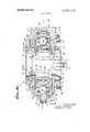
- FIG. Iis a view in perspective illustrating a tong assembly made in accordance with the invention.
- FIG. 2is a fragmentary top plan view of the assembly of FIG. ll, showing the tong head and transmission subassemblies;
- FIG. 3ais a fragmentary longitudinal section through the tong assembly as taken on the line L l-55 of FIG. 2, and showing the tong head;
- FIG. 3bis a continuation of FIG. 3a, showing the power transmission
- FIG. 4is a horizontal section taken on the line 4-4l of FIG. 3a:
- FIG. 5is a transverse section taken on the line 5-5 of FIG.
- FIG. 6is a fragmentary view partly :in section and partly in plan showing the reverse stop mechanism of the tong head
- FIG. 7is a view taken on the line 7-7 of FIG. ti;
- FIG. 8is a horizontal sectional view as taken on the line 8- ii of FIG. 3b;
- FIG. 9is a horizontal sectional view as taken on the line 9 9 of FIG. 312;
- FIG. I'llis a horizontal sectional view as taken on the line til-Id of FIG. 3b;
- FIG. IIis a fragmentary view in side elevation showing the manifold and control means for the motors, the case being broken away;
- FIG. 12is a view in rear end elevation of the structure of FIG. 11;
- FIG. I3is a view in section as taken on the line 1133-43 of FIG. I2, showing the compound control rock shaft assembly;
- FIG. I4is a view in section on the line I i-41 i of FIG. 112;
- FIG. I5is a view in section on the line 1l5ll5 ofFlG. 12;
- FIG. 16is a fragmentary view in side: elevation showing the connection of the actuator lever to the operating means for the motor control valves;
- FIG. I7is a fragmentary view in section as taken on the line 17-17 of FIG. lid.
- FIG. 18is a fragmentary view in section as taken on the line llb-ld of FIG. 17.
- a tong assembly embodying the inventionwill be seen to comprise three separate and distinct subassemblies comprising a pipe gripping or tong head assembly ll adapted to grip a joint and rotate the same relative to another joint, which joints together compose a threaded connection or joint between stands of well tubing or pipe or sucker rods, all of which are generically referred to herein as pipe, an illustrative length of which is generally illustrated at 2 and includes a joint or coupling 3.
- a power transmission subassemblygenerally denoted at 4i which contains drive means for effecting rotation of the pipe gripping mechanism included in the tong head.
- a plurality of motorsdesignated MI and M2 in the illustrative embodiment, these motors, as will hereinafter be more fully described, being adapted to drive the transmission mechanism at a relatively high speed and Iowtorque, on the one hand, and at a relatively low speed and high torque, on the other hand, and in opposite directions.
- the composite assemblyincludes a control subassembly generally denoted at 5 whereby an operator of the tong, in the making up and breaking out of pipe or rod joints, will be enabled to cause the motor M2 to operate in either selected direction, while motor MI remains idle so as to drive the pipe gripping mechanism at a relatively high rate of speed but at low torque, such as would be desirable when a joint is being initially made up and offers little resistance, such relatively high speed initial making up of the joint being generally referred to in the field as spinning.
- a control subassemblygenerally denoted at 5 whereby an operator of the tong, in the making up and breaking out of pipe or rod joints, will be enabled to cause the motor M2 to operate in either selected direction, while motor MI remains idle so as to drive the pipe gripping mechanism at a relatively high rate of speed but at low torque, such as would be desirable when a joint is being initially made up and offers little resistance, such relatively high speed initial making up of the joint being generally referred to in the field as spinning.
- the jointbe finally made up by the application of relatively high-torque forces which the tong operator may accomplish by causing, through the manipulation of the control mechanism 5, the simultaneous operation of motors M1 and M2 in such a manner that the transmission mechanism will impart to the gripping mechanism high-torque loads but at low speed, so as to shoulder or finally tighten up the joint.
- the gripping mechanismin the breaking out of a joint the gripping mechanism must impose high-torque loads on the joint in order to initiate its rotation so that the control mechanism 5 is adapted to enable the reverse rotation of both of the motors M1 and M2 in such a manner as to cause high torque, low-speed rotation of the pipe gripping mechanism to initially break out the joint, and thereafter, the control mechanism may be manipulated to allow the motor M1 to idle as the motor M2 continues to drive the pipe gripping mechanism at a relatively high speed under the reduced torque requirements for spinning the joint out.
- this subassemblycomprises a split case including an upper case section 6 and a lower case section 7 joined on substantially a median plane by suitable fasteners 8, the case defines a generally circular head end 9 which houses a pipe gripping mechanism generally denoted at C; and in a longitudinally extended, substantially rectangular case section 10 there is housed gear mechanism or other suitable drive means, to be hereinafter described, for effecting rotation of the pipe gripping means G.
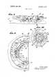
- the pipe gripping means Gcomprises an outer ring 11 which is of generally U-shape in cross section providing an inwardly opening channel 12.
- the outer ring '11is provided about its outer periphery with drive elements in a specifically illustrated form of gear teeth 13, so that the outer ring may be said to constitute a bull gear.
- Suitable bearing meansare provided for supporting the outer ring 1 1 for revolution within the case section 9, such bearing means being shown as ball bearings 14 engaging in annular races 15 formed about the outer wall of the outer ring 11 and riding in races 16 provided within the case section 9.
- Suitable seal rings 17may be provided between the case and a confronting portion of the outer ring 11 to prevent the entry of well fluids or other materials into the case section 9 which might otherwise cause damage to the drive mechanism for the outer ring 11.
- the outer ring 11is provided with diametrically opposing compound cam sections, each including a central low region 18 and oppositely extending rising surfaces 19, these rising surfaces each being formed on an arc or progressively decreasing radii from said low region, and the rising surfaces of the opposing cam sections, in the illustrative embodiment, meeting one another at a diametrical plane at right angles to a diametrical plane of the outer ring 11 extending through the low regions 18 of the camming sections.
- the portion of the rising cam surfaces 19 adjacent the low region 18 of the cam sectionsis formed on an arc having a greater radius than an intermediate portion of the rising surfaces, and the intermediate portions of the rising surfaces are struck on an arc of greater radius than the portions of the rising surfaces nearest the end thereof remote from the low gron.
- the inner ring assembly 20Revolvably disposed within the outer ring 1 1 is what may be typified as the inner ring assembly generally denoted at 20. Included in the inner ring assembly 20 (see FIGS. 3a, 4 and 5) is a pair of guide members, including an upper tubular guide 21 and a lower tubular guide 22, respectively having diametrically opposed, axially extended arms 23 and 24 which confront one another substantially at the midplane of the tong head.
- these armsdefine therebetween lateral openings 25 of rectangular form and in diametrically opposed relation, these openings leading into the central axially extended opening through the composite guides 21 and 22, this latter central opening constituting an opening through which pipe or rods may be extended as they are being run into or pulled from a well by the usual hoist equipment in the derrick, all as is well known in the art and in order to facilitate movement of couplings into and through the central opening of the guides, the upper guide 21 has a beveled or flared wall 26, and the lower guide 22 has a beveled or flared wall 27.
- Meansare provided for joining the guide sections in assembled relation, as well as for supporting in the lateral openings 25 a pair of hollow jaw guides 28, 28.
- Such meansincludes a pair of jaw guide clamps or plates 29, 29 which, as best seen in FIGS, 4 and 5, have a series of axially spaced grooves 30 and ribs 31 formed in an arcuate inner midsection of the plates 29 complementally with grooves 32 and ribs 33 formed in the arms 23 and 24 of the respective upper and lower guides 21 and 22. It will be understood that these complemental and coengaged ribs and grooves not only'support the jaw guide clamps or plated 29 on the composite guides, but also that these ribs and grooves hold the composite guide assembly together in the relationship as shown in FIG. 3a.
- the jaw guides 28constitute boxlike hollow members having sidewalls 34 provided with vertically extended external ribs 35 disposed in complemental vertical grooves 36 in the plates 29, suitable fastening means, such as screws 37, extending through the jaw guide walls 34 and into the clamp plates 29 so as to maintain all of the components, including the guides 21 and 22, the clamp plates 29, and the jaw guides 28, in an integrated assembly, with the jaw guides 28 extending radially outwardly into the channel 12 formed in the outer ring 11, as previously described.
- This integrated assemblyconstituting the inner ring 20, is adapted to be supported for rotation relative to the outer ring 11, and, illustratively, it will be noted that the upper guide 21 has an outwardly extended flange 38 which supports the inner ring assembly on the upper outer wall of the outer ring 11, while the corresponding flange 39 of the guide 22 is slightly downwardly spaced from the corresponding lower outer wall of the outer ring 11.
- the inner ring 20is disposed within the outer ring 11 for relative rotation thereof.
- the gripping mechanism Gfurther includes a pair of jaws 40, 40 slidably disposed within the jaw guides 28 for radial movement into and out of the central opening through the guides 21 and 22.
- a die carrier 41adapted to be removably retained in a seat 42 as by means of fasteners 43.
- cam follower meansin the form of a roller 44 supported on a vertical shaft 45 are provided in each jaw, these rollers 44 being engageable with the cam sections previously described in the outer ring 11.
- Meansare provided for normally biasing the jaws 40 outwardly to cause engagement of the rollers 44 with the cam sections, and such means (see FIG.
- coiled compression springs 46may comprise a suitable number of coiled compression springs 46 seated at one end in bores 47 in the sidewalls 34 of the jaw guides and abutting at their other ends against a foot provided on an L-shaped spring seat 48, a leg of which is disposed in a slot 49 in the jaw 40 and retained therein as by a pin 50.
- such brake meanscomprised a brake band 51 having friction material 52 thereon and engageable with the outer peripheral surface of the flange 39 of the lower guide 22, the brake band 51 being retained against downward displacement from the flange 39 by means of a bottom plate 53 secured to the case section 7 as by fasteners 54 and extending into underlying relation to the brake band.
- anchor meansare provided and, in the illustrative embodiment, such anchor means comprise ears 55 formed on the extremities of the brake band and extending downwardly through a slot 56 in the plate 53.
- the die holders 41previously referred to as constituting a part of the jaws 410, are provided with suitable die means, including a pair of similar dies 58, each having along vertical edges thereof teeth 59 adapted to bite into the coupling on engagement therewith.
- dies 58are disposed in dovetail siots 58a extending vertically in the die carriers 41 and generally disposed at an angle relative to the diametrical lines extending across the central opening through the guides, so that the dies will engage with one or another of the teeth 59 a substantial range of joint diameters without requiring changing of the dies 58 or the die carriers 61.
- the vertically toothed dies 59 herein illustratedmay be, moreover, replaced by arcuate toothed dies which more particularly are designed to fit with a particular joint diameter, as is well known in the art.
- the gripping means GFollowing the gripping and rotation of a joint part by the gripping means G, it is desired that the gripping means be released fromthe joint part in response to reversal of the direction of rotation of the outer ring 11 to cause return movement of the followers 414 to the low regions 18 of the camming sections within the outer ring.
- Meansare provided to prevent the continued relative rotation between the outer ring 11 and the inner ring to prevent the gripping means from again being actuated into gripping engagement with the joint part as a result of reversal of the rotation. Such means is best illustrated in FIGS.
- a flange 66is provided in overlying relation to the seal means 17, this flange 60 being secured to the upper wall of the outer ring 1 1 as by a suitable number of fasteners (not shown).
- annular seat 62in which is rotatably disposed a ring 63.
- a downwardly extended lug 64which extends into an upwardly opening slot 65 in a sliding block 66 having upstanding end lugs 67, 67.
- Coiled springs 68, 68are interposed between the opposing end lugs 67 and the intermediate lug 641 of the ring 63, and means are provided for causing rotation of the ring 63 relative to the flange 60, for example, a pair of outwardly extended lever arms 69 projecting outwardly from the ring 63 for manual engagement.
- the rela tive angular position of the ring 63is adapted to be adjusted within the limits of elongated arcuate slots 70 provided in the flange 611, locking screws 71 carried by the ring 63 extending through the slots 79 and into threaded engagement with the outer ring 11.
- stop elementsare provided on the guide 21, these stop elements being in the form of rollers 72 mounted in the outer peripheral wall of the flange 38 of guide 21 in angularly spaced relation and selectively engageable by floating rollers 73, one of which is adapted to be cammed inwardly for engagement with one of the rollers 72, depending upon the relative adjusted position of the ring 63.
- these floating rollers 73are adapted to be cammed inwardly by wedge surfaces 74 at the opposite ends of the floating block 66, these wedge surfaces 74 being opposed by wedge surfaces 75 formed in the inner periphery of the flange 60.
- the floating block 66is biased by one of the springs 68, depending upon the position of ring 63, to a position at which the opposing wedge surfaces 74 and 75 will hold one of the rollers 73 in a radially inwardly displaced position for engagement with one of the rollers 72.
- the outer ring assemblyis free for counterclockwise rotation relative to the inner ring guide 21, but clockwise rotation will be prevented.
- the tong head assemblymay be employed to turn a joint part in a counterclockwise direction, but the gripping means G will be prevented from reverse actuation when the outer ring 11 is rotated in the reverse direction, so that the inner ring 20 will be caused to rotate along with the outer ring 11 when the followers 44 are at the low regions 18 of the camming sections.
- the tong head case sections 6 and 7extend outwardly from the generally circular head end 9 thereof so as to form the boxlike section 10 of the case in which is disposed the illustrative gearing by which the bull gearlike outer ring 11 is to be driven.
- This gearingincludes a large ring gear 76 having a hub 77 journaled in bearings 78 supported between the case sections 6 and 7.
- the ring gear 76is in mesh with a pinion 79 which is journaled in bearings 80 mounted in the case sections 6 and 7 and adapted to be driven by a lower splined section 81 of a short splined shaft 82 which extends through an opening 83 in the upper case section 6, and, more particularly, through a horizontally extended wall 6a thereof which constitutes a portion of means, including the wall 6a, for connecting the tong head case to the power transmission mechanism 4 now to be described.
- This transmission means or section 41 of the assemblyalso comprises a longitudinally split case having an upper case section 85 and a lower case section 86 having a wall 860 mating with the wall 6a of head assembly 1 and suitably joined thereto as by fasteners 87, this wall 86a having an opening 88 aligned with opening 83 in head case wall 6a. .loumaled in the opening 88 is the hub 89 of a large ring gear 90 constituting the driven gear of the gearing means of the transmission.
- the short splined shaft 82previously described has a splined end 91 engaged in the hub 89 so that power is transmitted from the gear 911 to the head gearing 79, 76, 11.
- the motors M1 and M2 previously referred toare adapted to drive the ring gear 90, and, accordingly, these motors are mounted beneath a portion of the transmission case which extends rearwardly from the head case.
- the motor M1is preferably a hydraulicor other reversible fluid motor having an output shaft 92 on which is a pinion 93 engaged with ring gear 90 within the transmission case, so as to drive the ring gear 90 in opposite directions at a speed dependent upon the gear ratio and the flow of fluid through the motor M 1.
- Motor M2is also mounted beneath the transmission case adjacent motor M1 and has an output shaft 94 adapted to drive the ring gear 90 in opposite directions through double acting, self-energizing, overrunning clutch means C interposed between the drive pinion 95 and the motor shaft. 94.
- This clutch meansis illustrated in FIGS. 3b and 840 as including a power input or drive part 96 splined to the motor shaft 9 1 and a power output or driven part 97 journaled in the transmission case and integral with, or otherwise made a part of, the pinion 95.
- this overrunning clutch meansincludes camming surfaces 98 arranged in equidistantly spaced relation about the. drive part 96 and engageable with a like number of rollers 99 to urge the latter outwardly into driving relation with the inner periphery of a wall formed as a part of the driven clutch part 97 (see FIG. 8).
- These rollers 99are supported in a carrier ring 101 which also supports a plurality of equidistantly. spaced additional rollers or balls 102 engaged with he camming surfaces 98.
- This brake meansare provided so that when the drive part 96 is rotated in either direction relative to the driven part 97, the clutch will be engaged.
- This brake meanscomprises a cuplike brake drum 104 supported within the case section 86 between a pair of snap rings 105. Within the brake drum 104 is a discontinuous drag ring 106, the ends of which are spaced apart (see FIG.
- the roller carrier 101has an outward projection or abutment 107 extending into the space between the ends of the drag ring 106.
- the camming surfaces 98will force the balls 102 outwardly from their centralizing position transmitting the rotation to the roller carrier 101 until the pin 107, just referred to, engages one of the drag ring ends, depending upon the direction of rotation, whereupon further rotation of the roller carrier 101 will be resisted by frictional engagement of the drag ring 106 in the brake drum 104, and thus the rollers 99 will be forcibly cammed outwardly into engagement with the wall 100 of the driven part 97.
- Rotation of the brake drum 104 along with the drag ring 106is prevented by provision of a suitable stop, such as a pin 108, engaging the drum 104 and fixed in the case 86.
- the motor M1may drive the ring gear 90 in either direction and, unless the motor M2 is also operating to drive the clutch drive part 96, the clutch driven part 97 will idle along with the ring gear 90; however, when the motor M2 is operated to cause rotation of the clutch drive part 96, then both of the motors will be effective to drive the ring gear 90 in either direction, such selective operation of the motors M1 and M2 is adapted to be controlled by control means for the flow of fluid to the respective motors from a source, as will now be described.
- the control section 5 of the tong assemblyincludes a cover or case 109 which, as seen in FIG. 11, is adapted to be connected to the rear end of the transmission subassembly 4 on a supporting bracket 110 having ears 111 secured by fasteners 112 to the transmission case.
- a fluid manifold and valve assemblygenerally denoted at V, whereby to control the flow of power fluid from a source (not shown) to the respective motors M1 and M2.
- VSchematically illustrated in the valve and manifold assembly V, as seen in FIG.
- valve means V1 and V2respectively adapted to control the flow of motor fluid to the motors M1 and M2 under the influence of operating means generally denoted at O, which operating means is operable by actuator means generally denoted at A.
- valve V1is adapted to control the flow of fluid from the source leading into the manifold at an inlet 114 and leading from the manifold at an outlet 115 from the motor M1 in such a manner that fluid will flow from the inlet 1 14 through a valve passage 1 16 to motor M1 and from that motor through a conduit 117 and a valve passage 1 18 through the valve and to the outlet 115, so as to drive the motor Ml, say in a left-hand direction, when the valve is in a first position, the valve V1 is operable when it is in a second position to cause a reversal of the direction of flow so that the motor M1 will be driven in the opposite or right-hand direction.
- valve V2is adapted to control the flow of fluid through the motor M2 in reverse directions by causing the flow of fluid from the inlet 114 through a valve passage 119 and from the motor through a conduit 120 and thence a valve passage 121, whereby the motor M2 will rotate in a left-hand direction; and, when the valve V2 is adjusted to a second position, the flow of fluid will be reversed, causing the operation of the motor in a right-hand direction.
- valves and the flow passagesis merely illustrative and that any desired four-way valves or other valve means may be employed to accomplish the reversal of fluid flow through the two motors, but it is preferred that the operating means 0 be so constructed as to move the valve V1 to its first position or to its second position while the valve V2 remains closed, but, when it is desired, the valve V2 may be moved either simultaneously with, or after movement of, the valve V1 to its first and second positions.
- This operating meanscomprise a rock shaft 122 rotatably mounted in transversely extended relation by a pair of arms 123 depending from the bracket 110.
- the rock shaft 122is a hollow shaft within which is revolvably disposed a second rock shaft 124.
- the inner rock shaft 124has a lever arm 125 connected thereto and extending laterally through an opening 126 in the hollow rock shaft 122, this opening 126 being extended angularly so as to provide clearance space between end walls 127 and 128 thereof.
- the inner rock shaft 124also has a lever arm 129 projecting therefrom and through an opening 130 providing angularly spaced abutments 131 and 132 engageable with the lever arm in a manner hereinafter to be described.
- Carried by the lever arm 125is a valve operating linkage means 133 adapted to be connected to the valve V1 so as to move the latter between its first and second positions from its off position; and connected to the lever arm 129 is linkage means 134 adapted to be connected to the valve V2 to cause its operation between its first and second positions from its off position.
- the actuating means A for the operating means 0, just described,is located at one end of the rock shafts 122 and 124, but preferably at each end of said rock shafts, so as to enable operation of the tong assembly from either side thereof.
- the actuator meanscomprises a lever 135, the lever being pivotally supported on pins 136 which are carried by a member 137 which is connected to the hollow rock shaft 122, the pins 136 extending into the hollow rock shaft so as to effect rotation of the latter when the lever 135 is moved between a normal position in either direction.
- the rock shaft 1%extends endwise from the hollow shaft 122 and has secured to its outer end a lever 138 having an arm extending lengthwise of the lever 135 between upper and lower walls 139 and 140 of the lever 135. Between these walls 139 and 140 are camming means generally denoted at 141 and including an upper wedge surface 142 and a lower wedge surface 143 defining therebetween a central slot 144. These wedge surfaces and slot are adapted to cooperate with an end 145 on the actuator lever 138 only when the lever 135 is pivoted to a laterally displaced outer position as shown in broken lines in FIG. 17, so that when the lever 135 is in its normal position, shown in full lines in FIG. 17, and is moved either upwardly or downwardly, it will effect corresponding rotative movement of the hollow rock shaft 122; but when the lever 135 is pivoted about pins 136 to the angular position shown in broken lines in FIG. 17,
- the actuator lever 135is effective to cause either movement of the outer rock shaft 122 along, or together with the inner rock shaft 124, in opposite directions so as to effect either the operation of valve V2 upon abutment of either of the abutments 131 and 132 with the lever 129 or the simultaneous actuation of valve V1.
- the tongmay be driven at a high speed and low torque through the operation of the valve V1 upon movement of the lever 135 to a first position; upon movement of the lever 135 in the same direction to a second position, the valve V2 will be operated to cause operation of motor M1 which, through the clutch means previously described, will now work with motor M2 so that the tong will be driven at a lower speed and higher torque, as would be desirable when making up a joint.
- the actuator lever H35may be pivoted about pins 136 to effect coengagement of the lever 138 in the slot 1144 of the actuator lever 135 so that, when the lever is pivoted to actuate the valve mechanism, both valves V1 and V2 will be initially opened.
- the lever 135may be moved inwardly to the full line position of FIG. 17 so that the valve V2 will close, thereby allowing the tong to operate at high speed and low torque to spin out the joint.
- a tong headfor use in a power tong assembly having power transmission means for driving an output gear in opposite directions, said head comprising: a case having a gear therein adapted to receive a shaft driven by the output gear of said transmission means, said case having means including a wall for connecting said case to said transmission means, said case having a bull gear therein driven by the first mentioned gear provided with an internal circumferentially extended U- shaped channel, a tubular guide having a central opening extending axially thereof, said guide having means including selectively reversible reverse release stop means revolvably supporting the guide on said bull gear, jaw guides carried by said guide and extending radially therefrom into said channel, gripping jaws reciprocable in said jaw guides into and out of said opening, and cam and follower means in said channel and on said jaws for forcing said jaws into :said opening upon relative revolution of said guide and said bull gear,
- a tong head as defined in claim twherein brake means are provided on said frame to initially hold said guide against revolution with said bull gear.
- a tong head as defined in claim llwherein a pair of plates is connected with said arms, said jaw guides being connected between said plates.
Landscapes
- Engineering & Computer Science (AREA)
- Life Sciences & Earth Sciences (AREA)
- Geology (AREA)
- Mining & Mineral Resources (AREA)
- Mechanical Engineering (AREA)
- Physics & Mathematics (AREA)
- Environmental & Geological Engineering (AREA)
- Fluid Mechanics (AREA)
- General Life Sciences & Earth Sciences (AREA)
- Geochemistry & Mineralogy (AREA)
- Quick-Acting Or Multi-Walled Pipe Joints (AREA)
Abstract
Description
Claims (4)
Applications Claiming Priority (2)
| Application Number | Priority Date | Filing Date | Title |
|---|---|---|---|
| US67584367A | 1967-10-17 | 1967-10-17 | |
| US86211169A | 1969-07-22 | 1969-07-22 |
Publications (1)
| Publication Number | Publication Date |
|---|---|
| US3635105Atrue US3635105A (en) | 1972-01-18 |
Family
ID=27101425
Family Applications (1)
| Application Number | Title | Priority Date | Filing Date |
|---|---|---|---|
| US862111*AExpired - LifetimeUS3635105A (en) | 1967-10-17 | 1969-07-22 | Power tong head and assembly |
Country Status (1)
| Country | Link |
|---|---|
| US (1) | US3635105A (en) |
Cited By (61)
| Publication number | Priority date | Publication date | Assignee | Title |
|---|---|---|---|---|
| US4089240A (en)* | 1976-03-30 | 1978-05-16 | Eckel Manufacturing Co., Inc. | Power tongs |
| US4404876A (en)* | 1976-03-30 | 1983-09-20 | Eckel Manufacturing Co., Inc. | Power tongs |
| US4423645A (en) | 1981-06-10 | 1984-01-03 | Varco International, Inc. | Pipe spinner |
| US5044232A (en)* | 1988-12-01 | 1991-09-03 | Weatherford U.S., Inc. | Active jaw for a power tong |
| US5207128A (en)* | 1992-03-23 | 1993-05-04 | Weatherford-Petco, Inc. | Tong with floating jaws |
| WO1998032948A1 (en)* | 1997-01-29 | 1998-07-30 | Weatherford/Lamb, Inc. | Apparatus and method for aligning tubulars |
| WO2001079652A1 (en)* | 2000-04-17 | 2001-10-25 | Weatherford/Lamb, Inc. | Top drive for casing connection |
| US6330911B1 (en) | 1999-03-12 | 2001-12-18 | Weatherford/Lamb, Inc. | Tong |
| US6360633B2 (en) | 1997-01-29 | 2002-03-26 | Weatherford/Lamb, Inc. | Apparatus and method for aligning tubulars |
| US20020189863A1 (en)* | 1999-12-22 | 2002-12-19 | Mike Wardley | Drilling bit for drilling while running casing |
| US6527047B1 (en) | 1998-08-24 | 2003-03-04 | Weatherford/Lamb, Inc. | Method and apparatus for connecting tubulars using a top drive |
| US20030141111A1 (en)* | 2000-08-01 | 2003-07-31 | Giancarlo Pia | Drilling method |
| US20030164251A1 (en)* | 2000-04-28 | 2003-09-04 | Tulloch Rory Mccrae | Expandable apparatus for drift and reaming borehole |
| US6622796B1 (en) | 1998-12-24 | 2003-09-23 | Weatherford/Lamb, Inc. | Apparatus and method for facilitating the connection of tubulars using a top drive |
| US20030217865A1 (en)* | 2002-03-16 | 2003-11-27 | Simpson Neil Andrew Abercrombie | Bore lining and drilling |
| US20030221519A1 (en)* | 2000-03-14 | 2003-12-04 | Haugen David M. | Methods and apparatus for connecting tubulars while drilling |
| US20040045717A1 (en)* | 2002-09-05 | 2004-03-11 | Haugen David M. | Method and apparatus for reforming tubular connections |
| US6705405B1 (en) | 1998-08-24 | 2004-03-16 | Weatherford/Lamb, Inc. | Apparatus and method for connecting tubulars using a top drive |
| US20040069500A1 (en)* | 2001-05-17 | 2004-04-15 | Haugen David M. | Apparatus and methods for tubular makeup interlock |
| US6725938B1 (en) | 1998-12-24 | 2004-04-27 | Weatherford/Lamb, Inc. | Apparatus and method for facilitating the connection of tubulars using a top drive |
| US20040108142A1 (en)* | 1994-10-14 | 2004-06-10 | Weatherford/Lamb, Inc. | Methods and apparatus for cementing drill strings in place for one pass drilling and completion of oil and gas wells |
| US20040112646A1 (en)* | 1994-10-14 | 2004-06-17 | Vail William Banning | Method and apparatus for cementing drill strings in place for one pass drilling and completion of oil and gas wells |
| US20040118613A1 (en)* | 1994-10-14 | 2004-06-24 | Weatherford/Lamb, Inc. | Methods and apparatus for cementing drill strings in place for one pass drilling and completion of oil and gas wells |
| US20040129456A1 (en)* | 1994-10-14 | 2004-07-08 | Weatherford/Lamb, Inc. | Methods and apparatus for cementing drill strings in place for one pass drilling and completion of oil and gas wells |
| US20040140128A1 (en)* | 1994-10-14 | 2004-07-22 | Weatherford/Lamb, Inc. | Methods and apparatus for cementing drill strings in place for one pass drilling and completion of oil and gas wells |
| US20040216924A1 (en)* | 2003-03-05 | 2004-11-04 | Bernd-Georg Pietras | Casing running and drilling system |
| US20040216925A1 (en)* | 1998-12-22 | 2004-11-04 | Weatherford/Lamb, Inc. | Method and apparatus for drilling and lining a wellbore |
| US20040216892A1 (en)* | 2003-03-05 | 2004-11-04 | Giroux Richard L | Drilling with casing latch |
| US20040221997A1 (en)* | 1999-02-25 | 2004-11-11 | Weatherford/Lamb, Inc. | Methods and apparatus for wellbore construction and completion |
| US20040226751A1 (en)* | 2003-02-27 | 2004-11-18 | Mckay David | Drill shoe |
| US20040244992A1 (en)* | 2003-03-05 | 2004-12-09 | Carter Thurman B. | Full bore lined wellbores |
| US20040245020A1 (en)* | 2000-04-13 | 2004-12-09 | Weatherford/Lamb, Inc. | Apparatus and methods for drilling a wellbore using casing |
| US20040251025A1 (en)* | 2003-01-30 | 2004-12-16 | Giroux Richard L. | Single-direction cementing plug |
| US20040251055A1 (en)* | 2002-07-29 | 2004-12-16 | Weatherford/Lamb, Inc. | Adjustable rotating guides for spider or elevator |
| US20040251050A1 (en)* | 1997-09-02 | 2004-12-16 | Weatherford/Lamb, Inc. | Method and apparatus for drilling with casing |
| US20040262013A1 (en)* | 2002-10-11 | 2004-12-30 | Weatherford/Lamb, Inc. | Wired casing |
| US20050000696A1 (en)* | 2003-04-04 | 2005-01-06 | Mcdaniel Gary | Method and apparatus for handling wellbore tubulars |
| US20050000691A1 (en)* | 2000-04-17 | 2005-01-06 | Weatherford/Lamb, Inc. | Methods and apparatus for handling and drilling with tubulars or casing |
| US20050051343A1 (en)* | 1998-07-22 | 2005-03-10 | Weatherford/Lamb, Inc. | Apparatus for facilitating the connection of tubulars using a top drive |
| US20050121232A1 (en)* | 1998-12-22 | 2005-06-09 | Weatherford/Lamb, Inc. | Downhole filter |
| US20050194188A1 (en)* | 2003-10-03 | 2005-09-08 | Glaser Mark C. | Method of drilling and completing multiple wellbores inside a single caisson |
| US20050205250A1 (en)* | 2002-10-11 | 2005-09-22 | Weatherford/Lamb, Inc. | Apparatus and methods for drilling with casing |
| US20050217858A1 (en)* | 2002-12-13 | 2005-10-06 | Weatherford/Lamb, Inc. | Apparatus and method of drilling with casing |
| US6976298B1 (en) | 1998-08-24 | 2005-12-20 | Weatherford/Lamb, Inc. | Methods and apparatus for connecting tubulars using a top drive |
| US20060000600A1 (en)* | 1998-08-24 | 2006-01-05 | Bernd-Georg Pietras | Casing feeder |
| US20060032638A1 (en)* | 2004-07-30 | 2006-02-16 | Giroux Richard L | Apparatus and methods of setting and retrieving casing with drilling latch and bottom hole assembly |
| US7013997B2 (en) | 1994-10-14 | 2006-03-21 | Weatherford/Lamb, Inc. | Methods and apparatus for cementing drill strings in place for one pass drilling and completion of oil and gas wells |
| US7036610B1 (en) | 1994-10-14 | 2006-05-02 | Weatherford / Lamb, Inc. | Apparatus and method for completing oil and gas wells |
| US20060096751A1 (en)* | 2004-11-09 | 2006-05-11 | Matthew Brown | Top drive assembly |
| US20060180315A1 (en)* | 2005-01-18 | 2006-08-17 | David Shahin | Top drive torque booster |
| US7131505B2 (en) | 2002-12-30 | 2006-11-07 | Weatherford/Lamb, Inc. | Drilling with concentric strings of casing |
| US7228901B2 (en) | 1994-10-14 | 2007-06-12 | Weatherford/Lamb, Inc. | Method and apparatus for cementing drill strings in place for one pass drilling and completion of oil and gas wells |
| US7284617B2 (en) | 2004-05-20 | 2007-10-23 | Weatherford/Lamb, Inc. | Casing running head |
| US20070251701A1 (en)* | 2006-04-27 | 2007-11-01 | Michael Jahn | Torque sub for use with top drive |
| US20080125876A1 (en)* | 2006-11-17 | 2008-05-29 | Boutwell Doyle F | Top drive interlock |
| US7509722B2 (en) | 1997-09-02 | 2009-03-31 | Weatherford/Lamb, Inc. | Positioning and spinning device |
| US7650944B1 (en) | 2003-07-11 | 2010-01-26 | Weatherford/Lamb, Inc. | Vessel for well intervention |
| US7694744B2 (en) | 2005-01-12 | 2010-04-13 | Weatherford/Lamb, Inc. | One-position fill-up and circulating tool and method |
| US7874352B2 (en) | 2003-03-05 | 2011-01-25 | Weatherford/Lamb, Inc. | Apparatus for gripping a tubular on a drilling rig |
| USRE42877E1 (en) | 2003-02-07 | 2011-11-01 | Weatherford/Lamb, Inc. | Methods and apparatus for wellbore construction and completion |
| CN104209905A (en)* | 2014-09-02 | 2014-12-17 | 石蕴中 | Screwing type tubular and adjustable dual-use wrench |
Citations (3)
| Publication number | Priority date | Publication date | Assignee | Title |
|---|---|---|---|---|
| US2846909A (en)* | 1954-06-24 | 1958-08-12 | Mason Carlton Tool Co Inc | Power-driven pipe tong |
| US3180186A (en)* | 1961-08-01 | 1965-04-27 | Byron Jackson Inc | Power pipe tong with lost-motion jaw adjustment means |
| US3371562A (en)* | 1965-10-23 | 1968-03-05 | Benjamin F. Kelley | Grapple |
- 1969
- 1969-07-22USUS862111*Apatent/US3635105A/ennot_activeExpired - Lifetime
Patent Citations (3)
| Publication number | Priority date | Publication date | Assignee | Title |
|---|---|---|---|---|
| US2846909A (en)* | 1954-06-24 | 1958-08-12 | Mason Carlton Tool Co Inc | Power-driven pipe tong |
| US3180186A (en)* | 1961-08-01 | 1965-04-27 | Byron Jackson Inc | Power pipe tong with lost-motion jaw adjustment means |
| US3371562A (en)* | 1965-10-23 | 1968-03-05 | Benjamin F. Kelley | Grapple |
Cited By (146)
| Publication number | Priority date | Publication date | Assignee | Title |
|---|---|---|---|---|
| US4089240A (en)* | 1976-03-30 | 1978-05-16 | Eckel Manufacturing Co., Inc. | Power tongs |
| US4404876A (en)* | 1976-03-30 | 1983-09-20 | Eckel Manufacturing Co., Inc. | Power tongs |
| US4423645A (en) | 1981-06-10 | 1984-01-03 | Varco International, Inc. | Pipe spinner |
| US5044232A (en)* | 1988-12-01 | 1991-09-03 | Weatherford U.S., Inc. | Active jaw for a power tong |
| US5207128A (en)* | 1992-03-23 | 1993-05-04 | Weatherford-Petco, Inc. | Tong with floating jaws |
| US7165634B2 (en) | 1994-10-14 | 2007-01-23 | Weatherford/Lamb, Inc. | Method and apparatus for cementing drill strings in place for one pass drilling and completion of oil and gas wells |
| US20040129456A1 (en)* | 1994-10-14 | 2004-07-08 | Weatherford/Lamb, Inc. | Methods and apparatus for cementing drill strings in place for one pass drilling and completion of oil and gas wells |
| US7036610B1 (en) | 1994-10-14 | 2006-05-02 | Weatherford / Lamb, Inc. | Apparatus and method for completing oil and gas wells |
| US20040140128A1 (en)* | 1994-10-14 | 2004-07-22 | Weatherford/Lamb, Inc. | Methods and apparatus for cementing drill strings in place for one pass drilling and completion of oil and gas wells |
| US7013997B2 (en) | 1994-10-14 | 2006-03-21 | Weatherford/Lamb, Inc. | Methods and apparatus for cementing drill strings in place for one pass drilling and completion of oil and gas wells |
| US7228901B2 (en) | 1994-10-14 | 2007-06-12 | Weatherford/Lamb, Inc. | Method and apparatus for cementing drill strings in place for one pass drilling and completion of oil and gas wells |
| US7147068B2 (en) | 1994-10-14 | 2006-12-12 | Weatherford / Lamb, Inc. | Methods and apparatus for cementing drill strings in place for one pass drilling and completion of oil and gas wells |
| US7100710B2 (en) | 1994-10-14 | 2006-09-05 | Weatherford/Lamb, Inc. | Methods and apparatus for cementing drill strings in place for one pass drilling and completion of oil and gas wells |
| US20040118613A1 (en)* | 1994-10-14 | 2004-06-24 | Weatherford/Lamb, Inc. | Methods and apparatus for cementing drill strings in place for one pass drilling and completion of oil and gas wells |
| US20040124015A1 (en)* | 1994-10-14 | 2004-07-01 | Vail William Banning | Method and apparatus for cementing drill strings in place for one pass drilling and completion of oil and gas wells |
| US7040420B2 (en) | 1994-10-14 | 2006-05-09 | Weatherford/Lamb, Inc. | Methods and apparatus for cementing drill strings in place for one pass drilling and completion of oil and gas wells |
| US20040108142A1 (en)* | 1994-10-14 | 2004-06-10 | Weatherford/Lamb, Inc. | Methods and apparatus for cementing drill strings in place for one pass drilling and completion of oil and gas wells |
| US20040112646A1 (en)* | 1994-10-14 | 2004-06-17 | Vail William Banning | Method and apparatus for cementing drill strings in place for one pass drilling and completion of oil and gas wells |
| US7108084B2 (en) | 1994-10-14 | 2006-09-19 | Weatherford/Lamb, Inc. | Methods and apparatus for cementing drill strings in place for one pass drilling and completion of oil and gas wells |
| WO1998032948A1 (en)* | 1997-01-29 | 1998-07-30 | Weatherford/Lamb, Inc. | Apparatus and method for aligning tubulars |
| US6360633B2 (en) | 1997-01-29 | 2002-03-26 | Weatherford/Lamb, Inc. | Apparatus and method for aligning tubulars |
| US7140445B2 (en) | 1997-09-02 | 2006-11-28 | Weatherford/Lamb, Inc. | Method and apparatus for drilling with casing |
| US7509722B2 (en) | 1997-09-02 | 2009-03-31 | Weatherford/Lamb, Inc. | Positioning and spinning device |
| US20040251050A1 (en)* | 1997-09-02 | 2004-12-16 | Weatherford/Lamb, Inc. | Method and apparatus for drilling with casing |
| US20050051343A1 (en)* | 1998-07-22 | 2005-03-10 | Weatherford/Lamb, Inc. | Apparatus for facilitating the connection of tubulars using a top drive |
| US7665531B2 (en) | 1998-07-22 | 2010-02-23 | Weatherford/Lamb, Inc. | Apparatus for facilitating the connection of tubulars using a top drive |
| US20070074876A1 (en)* | 1998-07-22 | 2007-04-05 | Bernd-Georg Pietras | Apparatus for facilitating the connection of tubulars using a top drive |
| US20050269105A1 (en)* | 1998-07-22 | 2005-12-08 | Weatherford/Lamb, Inc. | Apparatus for facilitating the connection of tubulars using a top drive |
| US7137454B2 (en) | 1998-07-22 | 2006-11-21 | Weatherford/Lamb, Inc. | Apparatus for facilitating the connection of tubulars using a top drive |
| US20040173357A1 (en)* | 1998-08-24 | 2004-09-09 | Weatherford/Lamb, Inc. | Apparatus for connecting tublars using a top drive |
| US7513300B2 (en) | 1998-08-24 | 2009-04-07 | Weatherford/Lamb, Inc. | Casing running and drilling system |
| US20040149451A1 (en)* | 1998-08-24 | 2004-08-05 | Weatherford/Lamb, Inc. | Method and apparatus for connecting tubulars using a top drive |
| US20070051519A1 (en)* | 1998-08-24 | 2007-03-08 | Bernd-Georg Pietras | apparatus for connecting tubulars using a top drive |
| US7669662B2 (en) | 1998-08-24 | 2010-03-02 | Weatherford/Lamb, Inc. | Casing feeder |
| US7021374B2 (en) | 1998-08-24 | 2006-04-04 | Weatherford/Lamb, Inc. | Method and apparatus for connecting tubulars using a top drive |
| US6705405B1 (en) | 1998-08-24 | 2004-03-16 | Weatherford/Lamb, Inc. | Apparatus and method for connecting tubulars using a top drive |
| US7219744B2 (en) | 1998-08-24 | 2007-05-22 | Weatherford/Lamb, Inc. | Method and apparatus for connecting tubulars using a top drive |
| US7090021B2 (en) | 1998-08-24 | 2006-08-15 | Bernd-Georg Pietras | Apparatus for connecting tublars using a top drive |
| US6527047B1 (en) | 1998-08-24 | 2003-03-04 | Weatherford/Lamb, Inc. | Method and apparatus for connecting tubulars using a top drive |
| US7617866B2 (en) | 1998-08-24 | 2009-11-17 | Weatherford/Lamb, Inc. | Methods and apparatus for connecting tubulars using a top drive |
| US7353880B2 (en) | 1998-08-24 | 2008-04-08 | Weatherford/Lamb, Inc. | Method and apparatus for connecting tubulars using a top drive |
| US6688398B2 (en) | 1998-08-24 | 2004-02-10 | Weatherford/Lamb, Inc. | Method and apparatus for connecting tubulars using a top drive |
| US20070193751A1 (en)* | 1998-08-24 | 2007-08-23 | Bernd-Georg Pietras | Casing running and drilling system |
| US20060000600A1 (en)* | 1998-08-24 | 2006-01-05 | Bernd-Georg Pietras | Casing feeder |
| US6976298B1 (en) | 1998-08-24 | 2005-12-20 | Weatherford/Lamb, Inc. | Methods and apparatus for connecting tubulars using a top drive |
| US7451826B2 (en) | 1998-08-24 | 2008-11-18 | Weatherford/Lamb, Inc. | Apparatus for connecting tubulars using a top drive |
| US7188687B2 (en) | 1998-12-22 | 2007-03-13 | Weatherford/Lamb, Inc. | Downhole filter |
| US20040216925A1 (en)* | 1998-12-22 | 2004-11-04 | Weatherford/Lamb, Inc. | Method and apparatus for drilling and lining a wellbore |
| US7117957B2 (en) | 1998-12-22 | 2006-10-10 | Weatherford/Lamb, Inc. | Methods for drilling and lining a wellbore |
| US20050121232A1 (en)* | 1998-12-22 | 2005-06-09 | Weatherford/Lamb, Inc. | Downhole filter |
| US7128161B2 (en) | 1998-12-24 | 2006-10-31 | Weatherford/Lamb, Inc. | Apparatus and methods for facilitating the connection of tubulars using a top drive |
| US20060011353A1 (en)* | 1998-12-24 | 2006-01-19 | Weatherford/Lamb, Inc. | Apparatus and methods for facilitating the connection of tubulars using a top drive |
| US20040194965A1 (en)* | 1998-12-24 | 2004-10-07 | Weatherford/Lamb, Inc. | Apparatus and method for facilitating the connection of tubulars using a top drive |
| US6622796B1 (en) | 1998-12-24 | 2003-09-23 | Weatherford/Lamb, Inc. | Apparatus and method for facilitating the connection of tubulars using a top drive |
| US6725938B1 (en) | 1998-12-24 | 2004-04-27 | Weatherford/Lamb, Inc. | Apparatus and method for facilitating the connection of tubulars using a top drive |
| US7004259B2 (en) | 1998-12-24 | 2006-02-28 | Weatherford/Lamb, Inc. | Apparatus and method for facilitating the connection of tubulars using a top drive |
| US20040011531A1 (en)* | 1998-12-24 | 2004-01-22 | Weatherford/Lamb, Inc. | Apparatus and method for facilitating the connection of tubulars using a top drive |
| US7213656B2 (en) | 1998-12-24 | 2007-05-08 | Weatherford/Lamb, Inc. | Apparatus and method for facilitating the connection of tubulars using a top drive |
| US7311148B2 (en) | 1999-02-25 | 2007-12-25 | Weatherford/Lamb, Inc. | Methods and apparatus for wellbore construction and completion |
| US20040221997A1 (en)* | 1999-02-25 | 2004-11-11 | Weatherford/Lamb, Inc. | Methods and apparatus for wellbore construction and completion |
| US6330911B1 (en) | 1999-03-12 | 2001-12-18 | Weatherford/Lamb, Inc. | Tong |
| US20020189863A1 (en)* | 1999-12-22 | 2002-12-19 | Mike Wardley | Drilling bit for drilling while running casing |
| US7216727B2 (en) | 1999-12-22 | 2007-05-15 | Weatherford/Lamb, Inc. | Drilling bit for drilling while running casing |
| US20030221519A1 (en)* | 2000-03-14 | 2003-12-04 | Haugen David M. | Methods and apparatus for connecting tubulars while drilling |
| US7107875B2 (en) | 2000-03-14 | 2006-09-19 | Weatherford/Lamb, Inc. | Methods and apparatus for connecting tubulars while drilling |
| US20040245020A1 (en)* | 2000-04-13 | 2004-12-09 | Weatherford/Lamb, Inc. | Apparatus and methods for drilling a wellbore using casing |
| US7334650B2 (en) | 2000-04-13 | 2008-02-26 | Weatherford/Lamb, Inc. | Apparatus and methods for drilling a wellbore using casing |
| US20070119626A9 (en)* | 2000-04-13 | 2007-05-31 | Weatherford/Lamb, Inc. | Apparatus and methods for drilling a wellbore using casing |
| US20070056774A9 (en)* | 2000-04-13 | 2007-03-15 | Weatherford/Lamb, Inc. | Apparatus and methods for drilling a wellbore using casing |
| US7654325B2 (en) | 2000-04-17 | 2010-02-02 | Weatherford/Lamb, Inc. | Methods and apparatus for handling and drilling with tubulars or casing |
| US7793719B2 (en) | 2000-04-17 | 2010-09-14 | Weatherford/Lamb, Inc. | Top drive casing system |
| US20050000691A1 (en)* | 2000-04-17 | 2005-01-06 | Weatherford/Lamb, Inc. | Methods and apparatus for handling and drilling with tubulars or casing |
| US20080110637A1 (en)* | 2000-04-17 | 2008-05-15 | Randy Gene Snider | Top drive casing system |
| EP1970526A3 (en)* | 2000-04-17 | 2009-01-28 | Weatherford/Lamb, Inc. | Top drive for casing connection |
| EP1659258A3 (en)* | 2000-04-17 | 2006-07-05 | Weatherford/Lamb, Inc. | Top drive for casing connection |
| WO2001079652A1 (en)* | 2000-04-17 | 2001-10-25 | Weatherford/Lamb, Inc. | Top drive for casing connection |
| US7325610B2 (en) | 2000-04-17 | 2008-02-05 | Weatherford/Lamb, Inc. | Methods and apparatus for handling and drilling with tubulars or casing |
| US7712523B2 (en) | 2000-04-17 | 2010-05-11 | Weatherford/Lamb, Inc. | Top drive casing system |
| US20080059073A1 (en)* | 2000-04-17 | 2008-03-06 | Giroux Richard L | Methods and apparatus for handling and drilling with tubulars or casing |
| US6536520B1 (en) | 2000-04-17 | 2003-03-25 | Weatherford/Lamb, Inc. | Top drive casing system |
| US7918273B2 (en) | 2000-04-17 | 2011-04-05 | Weatherford/Lamb, Inc. | Top drive casing system |
| NO339602B1 (en)* | 2000-04-17 | 2017-01-09 | Weatherford Tech Holdings Llc | Top-powered rotary system for connecting feeding tubes |
| US20030173073A1 (en)* | 2000-04-17 | 2003-09-18 | Weatherford/Lamb, Inc. | Top drive casing system |
| US20030164251A1 (en)* | 2000-04-28 | 2003-09-04 | Tulloch Rory Mccrae | Expandable apparatus for drift and reaming borehole |
| US7100713B2 (en) | 2000-04-28 | 2006-09-05 | Weatherford/Lamb, Inc. | Expandable apparatus for drift and reaming borehole |
| US20030141111A1 (en)* | 2000-08-01 | 2003-07-31 | Giancarlo Pia | Drilling method |
| US7093675B2 (en) | 2000-08-01 | 2006-08-22 | Weatherford/Lamb, Inc. | Drilling method |
| US20060169461A1 (en)* | 2001-05-17 | 2006-08-03 | Weatherford/Lamb, Inc. | Apparatus and methods for tubular makeup interlock |
| US20040173358A1 (en)* | 2001-05-17 | 2004-09-09 | Weatherford/Lamb, Inc. | Apparatus and methods for tubular makeup interlock |
| US20040069500A1 (en)* | 2001-05-17 | 2004-04-15 | Haugen David M. | Apparatus and methods for tubular makeup interlock |
| US6938697B2 (en) | 2001-05-17 | 2005-09-06 | Weatherford/Lamb, Inc. | Apparatus and methods for tubular makeup interlock |
| US7896084B2 (en) | 2001-05-17 | 2011-03-01 | Weatherford/Lamb, Inc. | Apparatus and methods for tubular makeup interlock |
| US6742596B2 (en) | 2001-05-17 | 2004-06-01 | Weatherford/Lamb, Inc. | Apparatus and methods for tubular makeup interlock |
| US7281587B2 (en) | 2001-05-17 | 2007-10-16 | Weatherford/Lamb, Inc. | Apparatus and methods for tubular makeup interlock |
| US8517090B2 (en) | 2001-05-17 | 2013-08-27 | Weatherford/Lamb, Inc. | Apparatus and methods for tubular makeup interlock |
| US7073598B2 (en) | 2001-05-17 | 2006-07-11 | Weatherford/Lamb, Inc. | Apparatus and methods for tubular makeup interlock |
| US20030217865A1 (en)* | 2002-03-16 | 2003-11-27 | Simpson Neil Andrew Abercrombie | Bore lining and drilling |
| US7004264B2 (en) | 2002-03-16 | 2006-02-28 | Weatherford/Lamb, Inc. | Bore lining and drilling |
| US6994176B2 (en) | 2002-07-29 | 2006-02-07 | Weatherford/Lamb, Inc. | Adjustable rotating guides for spider or elevator |
| US20060124357A1 (en)* | 2002-07-29 | 2006-06-15 | Weatherford/Lamb, Inc. | Adjustable rotating guides for spider or elevator |
| US20040251055A1 (en)* | 2002-07-29 | 2004-12-16 | Weatherford/Lamb, Inc. | Adjustable rotating guides for spider or elevator |
| US7448456B2 (en) | 2002-07-29 | 2008-11-11 | Weatherford/Lamb, Inc. | Adjustable rotating guides for spider or elevator |
| US20040045717A1 (en)* | 2002-09-05 | 2004-03-11 | Haugen David M. | Method and apparatus for reforming tubular connections |
| US7100697B2 (en) | 2002-09-05 | 2006-09-05 | Weatherford/Lamb, Inc. | Method and apparatus for reforming tubular connections |
| US7090023B2 (en) | 2002-10-11 | 2006-08-15 | Weatherford/Lamb, Inc. | Apparatus and methods for drilling with casing |
| US20040262013A1 (en)* | 2002-10-11 | 2004-12-30 | Weatherford/Lamb, Inc. | Wired casing |
| US20050205250A1 (en)* | 2002-10-11 | 2005-09-22 | Weatherford/Lamb, Inc. | Apparatus and methods for drilling with casing |
| US7303022B2 (en) | 2002-10-11 | 2007-12-04 | Weatherford/Lamb, Inc. | Wired casing |
| US20050217858A1 (en)* | 2002-12-13 | 2005-10-06 | Weatherford/Lamb, Inc. | Apparatus and method of drilling with casing |
| US7083005B2 (en) | 2002-12-13 | 2006-08-01 | Weatherford/Lamb, Inc. | Apparatus and method of drilling with casing |
| US7131505B2 (en) | 2002-12-30 | 2006-11-07 | Weatherford/Lamb, Inc. | Drilling with concentric strings of casing |
| US7128154B2 (en) | 2003-01-30 | 2006-10-31 | Weatherford/Lamb, Inc. | Single-direction cementing plug |
| US20040251025A1 (en)* | 2003-01-30 | 2004-12-16 | Giroux Richard L. | Single-direction cementing plug |
| USRE42877E1 (en) | 2003-02-07 | 2011-11-01 | Weatherford/Lamb, Inc. | Methods and apparatus for wellbore construction and completion |
| US7096982B2 (en) | 2003-02-27 | 2006-08-29 | Weatherford/Lamb, Inc. | Drill shoe |
| US20040226751A1 (en)* | 2003-02-27 | 2004-11-18 | Mckay David | Drill shoe |
| US20110174483A1 (en)* | 2003-03-05 | 2011-07-21 | Odell Ii Albert C | Apparatus for gripping a tubular on a drilling rig |
| US7413020B2 (en) | 2003-03-05 | 2008-08-19 | Weatherford/Lamb, Inc. | Full bore lined wellbores |
| US7874352B2 (en) | 2003-03-05 | 2011-01-25 | Weatherford/Lamb, Inc. | Apparatus for gripping a tubular on a drilling rig |
| US7191840B2 (en) | 2003-03-05 | 2007-03-20 | Weatherford/Lamb, Inc. | Casing running and drilling system |
| US8567512B2 (en) | 2003-03-05 | 2013-10-29 | Weatherford/Lamb, Inc. | Apparatus for gripping a tubular on a drilling rig |
| US20040244992A1 (en)* | 2003-03-05 | 2004-12-09 | Carter Thurman B. | Full bore lined wellbores |
| US7360594B2 (en) | 2003-03-05 | 2008-04-22 | Weatherford/Lamb, Inc. | Drilling with casing latch |
| US20040216892A1 (en)* | 2003-03-05 | 2004-11-04 | Giroux Richard L | Drilling with casing latch |
| US20040216924A1 (en)* | 2003-03-05 | 2004-11-04 | Bernd-Georg Pietras | Casing running and drilling system |
| US10138690B2 (en) | 2003-03-05 | 2018-11-27 | Weatherford Technology Holdings, Llc | Apparatus for gripping a tubular on a drilling rig |
| US20050000696A1 (en)* | 2003-04-04 | 2005-01-06 | Mcdaniel Gary | Method and apparatus for handling wellbore tubulars |
| US7370707B2 (en) | 2003-04-04 | 2008-05-13 | Weatherford/Lamb, Inc. | Method and apparatus for handling wellbore tubulars |
| US7650944B1 (en) | 2003-07-11 | 2010-01-26 | Weatherford/Lamb, Inc. | Vessel for well intervention |
| US7264067B2 (en) | 2003-10-03 | 2007-09-04 | Weatherford/Lamb, Inc. | Method of drilling and completing multiple wellbores inside a single caisson |
| US20050194188A1 (en)* | 2003-10-03 | 2005-09-08 | Glaser Mark C. | Method of drilling and completing multiple wellbores inside a single caisson |
| US7284617B2 (en) | 2004-05-20 | 2007-10-23 | Weatherford/Lamb, Inc. | Casing running head |
| US7503397B2 (en) | 2004-07-30 | 2009-03-17 | Weatherford/Lamb, Inc. | Apparatus and methods of setting and retrieving casing with drilling latch and bottom hole assembly |
| US20060032638A1 (en)* | 2004-07-30 | 2006-02-16 | Giroux Richard L | Apparatus and methods of setting and retrieving casing with drilling latch and bottom hole assembly |
| US20060096751A1 (en)* | 2004-11-09 | 2006-05-11 | Matthew Brown | Top drive assembly |
| US20070240908A1 (en)* | 2004-11-09 | 2007-10-18 | Tesco Corporation | Top drive assembly |
| US7270189B2 (en)* | 2004-11-09 | 2007-09-18 | Tesco Corporation | Top drive assembly |
| US7694744B2 (en) | 2005-01-12 | 2010-04-13 | Weatherford/Lamb, Inc. | One-position fill-up and circulating tool and method |
| US7845418B2 (en) | 2005-01-18 | 2010-12-07 | Weatherford/Lamb, Inc. | Top drive torque booster |
| US20060180315A1 (en)* | 2005-01-18 | 2006-08-17 | David Shahin | Top drive torque booster |
| US7757759B2 (en) | 2006-04-27 | 2010-07-20 | Weatherford/Lamb, Inc. | Torque sub for use with top drive |
| US20070251701A1 (en)* | 2006-04-27 | 2007-11-01 | Michael Jahn | Torque sub for use with top drive |
| US20080125876A1 (en)* | 2006-11-17 | 2008-05-29 | Boutwell Doyle F | Top drive interlock |
| US7882902B2 (en) | 2006-11-17 | 2011-02-08 | Weatherford/Lamb, Inc. | Top drive interlock |
| CN104209905B (en)* | 2014-09-02 | 2016-01-20 | 石蕴中 | Screwing type pipe combination wrenches alive |
| CN104209905A (en)* | 2014-09-02 | 2014-12-17 | 石蕴中 | Screwing type tubular and adjustable dual-use wrench |
Similar Documents
| Publication | Publication Date | Title |
|---|---|---|
| US3635105A (en) | Power tong head and assembly | |
| US3518903A (en) | Combined power tong and backup tong assembly | |
| US4099429A (en) | Pipe-spinning apparatus and method | |
| US3691875A (en) | Chain driven spinning, make up and break out tongs | |
| US4084453A (en) | Power tongs | |
| US4404876A (en) | Power tongs | |
| US2618468A (en) | Power tong | |
| US2703221A (en) | Power tongs | |
| US3380323A (en) | Power wrench | |
| JPS6144541A (en) | Back-up-tongue and method of ensuring no-revolution of tubular member and power tongue | |
| US3507174A (en) | Backup tong for power pipe tongs | |
| US2615682A (en) | Power-operated slidable jaw pipe tong | |
| US3196717A (en) | Pipe gripping mechanism for casing tongs | |
| US2311225A (en) | Pipe rotating apparatus | |
| US3625095A (en) | Drive for pipe tongs | |
| US4089240A (en) | Power tongs | |
| US3516308A (en) | Power pipe tong transmission assembly | |
| US2405757A (en) | Pipe wrench | |
| US3550485A (en) | Power pipe tongs with variable brake | |
| US2400712A (en) | Drill pipe spinner | |
| US3483774A (en) | Power tong head and assembly | |
| US2594666A (en) | Clutch assembly for drawworks | |
| US3481229A (en) | Power tong assembly and transmission means therefor | |
| US3739663A (en) | Chain actuated pipe tongs | |
| US4572036A (en) | Power tong and jaw apparatus |
Legal Events
| Date | Code | Title | Description |
|---|---|---|---|
| AS | Assignment | Owner name:HUGHES TOOL COMPANY, P.O. BOX 2539, HOUSTON, TX. 7 Free format text:ASSIGNMENT OF ASSIGNORS INTEREST.;ASSIGNOR:BJ-HUGHES INC.,;REEL/FRAME:004098/0273 Effective date:19821231 | |
| AS | Assignment | Owner name:BAKER HUGHES INCORPORATED, TEXAS Free format text:ASSIGNMENT OF ASSIGNORS INTEREST.;ASSIGNOR:HUGHES TOOL COMPANY;REEL/FRAME:005050/0861 Effective date:19880609 | |
| AS | Assignment | Owner name:HUGHES TOOL COMPANY-USA, A DE CORP.,TEXAS Free format text:ASSIGNMENT OF ASSIGNORS INTEREST;ASSIGNOR:BAKER HUGHES INCORPORATED;REEL/FRAME:004944/0763 Effective date:19880718 Owner name:HUGHES TOOL COMPANY-USA, 5425 POLK AVE., HOUSTON, Free format text:ASSIGNMENT OF ASSIGNORS INTEREST.;ASSIGNOR:BAKER HUGHES INCORPORATED;REEL/FRAME:004944/0763 Effective date:19880718 | |
| AS | Assignment | Owner name:VARCO INTERNATIONAL, INC., A CA. CORP., CALIFORNIA Free format text:ASSIGNMENT OF ASSIGNORS INTEREST.;ASSIGNOR:HUGHES TOOL CONPANY-USA;REEL/FRAME:005013/0843 Effective date:19880929 |