US3631542A - Myoelectric brace - Google Patents
Myoelectric braceDownload PDFInfo
- Publication number
- US3631542A US3631542AUS848919AUS3631542DAUS3631542AUS 3631542 AUS3631542 AUS 3631542AUS 848919 AUS848919 AUS 848919AUS 3631542D AUS3631542D AUS 3631542DAUS 3631542 AUS3631542 AUS 3631542A
- Authority
- US
- United States
- Prior art keywords
- muscle
- actuator
- finger support
- motor
- causes
- Prior art date
- Legal status (The legal status is an assumption and is not a legal conclusion. Google has not performed a legal analysis and makes no representation as to the accuracy of the status listed.)
- Expired - Lifetime
Links
Images

Classifications
- A—HUMAN NECESSITIES
- A61—MEDICAL OR VETERINARY SCIENCE; HYGIENE
- A61F—FILTERS IMPLANTABLE INTO BLOOD VESSELS; PROSTHESES; DEVICES PROVIDING PATENCY TO, OR PREVENTING COLLAPSING OF, TUBULAR STRUCTURES OF THE BODY, e.g. STENTS; ORTHOPAEDIC, NURSING OR CONTRACEPTIVE DEVICES; FOMENTATION; TREATMENT OR PROTECTION OF EYES OR EARS; BANDAGES, DRESSINGS OR ABSORBENT PADS; FIRST-AID KITS
- A61F2/00—Filters implantable into blood vessels; Prostheses, i.e. artificial substitutes or replacements for parts of the body; Appliances for connecting them with the body; Devices providing patency to, or preventing collapsing of, tubular structures of the body, e.g. stents
- A61F2/50—Prostheses not implantable in the body
- A61F2/68—Operating or control means
- A61F2/70—Operating or control means electrical
- A61F2/72—Bioelectric control, e.g. myoelectric
- A—HUMAN NECESSITIES
- A61—MEDICAL OR VETERINARY SCIENCE; HYGIENE
- A61F—FILTERS IMPLANTABLE INTO BLOOD VESSELS; PROSTHESES; DEVICES PROVIDING PATENCY TO, OR PREVENTING COLLAPSING OF, TUBULAR STRUCTURES OF THE BODY, e.g. STENTS; ORTHOPAEDIC, NURSING OR CONTRACEPTIVE DEVICES; FOMENTATION; TREATMENT OR PROTECTION OF EYES OR EARS; BANDAGES, DRESSINGS OR ABSORBENT PADS; FIRST-AID KITS
- A61F2/00—Filters implantable into blood vessels; Prostheses, i.e. artificial substitutes or replacements for parts of the body; Appliances for connecting them with the body; Devices providing patency to, or preventing collapsing of, tubular structures of the body, e.g. stents
- A61F2/50—Prostheses not implantable in the body
- A61F2/68—Operating or control means
- A61F2/74—Operating or control means fluid, i.e. hydraulic or pneumatic
- A61F2/741—Operating or control means fluid, i.e. hydraulic or pneumatic using powered actuators, e.g. stepper motors or solenoids
- A—HUMAN NECESSITIES
- A61—MEDICAL OR VETERINARY SCIENCE; HYGIENE
- A61F—FILTERS IMPLANTABLE INTO BLOOD VESSELS; PROSTHESES; DEVICES PROVIDING PATENCY TO, OR PREVENTING COLLAPSING OF, TUBULAR STRUCTURES OF THE BODY, e.g. STENTS; ORTHOPAEDIC, NURSING OR CONTRACEPTIVE DEVICES; FOMENTATION; TREATMENT OR PROTECTION OF EYES OR EARS; BANDAGES, DRESSINGS OR ABSORBENT PADS; FIRST-AID KITS
- A61F2/00—Filters implantable into blood vessels; Prostheses, i.e. artificial substitutes or replacements for parts of the body; Appliances for connecting them with the body; Devices providing patency to, or preventing collapsing of, tubular structures of the body, e.g. stents
- A61F2/50—Prostheses not implantable in the body
- A61F2/68—Operating or control means
- A61F2/74—Operating or control means fluid, i.e. hydraulic or pneumatic
- A61F2/748—Valve systems
- A—HUMAN NECESSITIES
- A61—MEDICAL OR VETERINARY SCIENCE; HYGIENE
- A61F—FILTERS IMPLANTABLE INTO BLOOD VESSELS; PROSTHESES; DEVICES PROVIDING PATENCY TO, OR PREVENTING COLLAPSING OF, TUBULAR STRUCTURES OF THE BODY, e.g. STENTS; ORTHOPAEDIC, NURSING OR CONTRACEPTIVE DEVICES; FOMENTATION; TREATMENT OR PROTECTION OF EYES OR EARS; BANDAGES, DRESSINGS OR ABSORBENT PADS; FIRST-AID KITS
- A61F5/00—Orthopaedic methods or devices for non-surgical treatment of bones or joints; Nursing devices ; Anti-rape devices
- A61F5/01—Orthopaedic devices, e.g. long-term immobilising or pressure directing devices for treating broken or deformed bones such as splints, casts or braces
- A61F5/0102—Orthopaedic devices, e.g. long-term immobilising or pressure directing devices for treating broken or deformed bones such as splints, casts or braces specially adapted for correcting deformities of the limbs or for supporting them; Ortheses, e.g. with articulations
- A61F5/013—Orthopaedic devices, e.g. long-term immobilising or pressure directing devices for treating broken or deformed bones such as splints, casts or braces specially adapted for correcting deformities of the limbs or for supporting them; Ortheses, e.g. with articulations for the arms, hands or fingers
- B—PERFORMING OPERATIONS; TRANSPORTING
- B25—HAND TOOLS; PORTABLE POWER-DRIVEN TOOLS; MANIPULATORS
- B25J—MANIPULATORS; CHAMBERS PROVIDED WITH MANIPULATION DEVICES
- B25J9/00—Programme-controlled manipulators
- B25J9/0006—Exoskeletons, i.e. resembling a human figure
- A—HUMAN NECESSITIES
- A61—MEDICAL OR VETERINARY SCIENCE; HYGIENE
- A61F—FILTERS IMPLANTABLE INTO BLOOD VESSELS; PROSTHESES; DEVICES PROVIDING PATENCY TO, OR PREVENTING COLLAPSING OF, TUBULAR STRUCTURES OF THE BODY, e.g. STENTS; ORTHOPAEDIC, NURSING OR CONTRACEPTIVE DEVICES; FOMENTATION; TREATMENT OR PROTECTION OF EYES OR EARS; BANDAGES, DRESSINGS OR ABSORBENT PADS; FIRST-AID KITS
- A61F2/00—Filters implantable into blood vessels; Prostheses, i.e. artificial substitutes or replacements for parts of the body; Appliances for connecting them with the body; Devices providing patency to, or preventing collapsing of, tubular structures of the body, e.g. stents
- A61F2/50—Prostheses not implantable in the body
- A61F2/68—Operating or control means
- A61F2/74—Operating or control means fluid, i.e. hydraulic or pneumatic
- A—HUMAN NECESSITIES
- A61—MEDICAL OR VETERINARY SCIENCE; HYGIENE
- A61F—FILTERS IMPLANTABLE INTO BLOOD VESSELS; PROSTHESES; DEVICES PROVIDING PATENCY TO, OR PREVENTING COLLAPSING OF, TUBULAR STRUCTURES OF THE BODY, e.g. STENTS; ORTHOPAEDIC, NURSING OR CONTRACEPTIVE DEVICES; FOMENTATION; TREATMENT OR PROTECTION OF EYES OR EARS; BANDAGES, DRESSINGS OR ABSORBENT PADS; FIRST-AID KITS
- A61F2/00—Filters implantable into blood vessels; Prostheses, i.e. artificial substitutes or replacements for parts of the body; Appliances for connecting them with the body; Devices providing patency to, or preventing collapsing of, tubular structures of the body, e.g. stents
- A61F2/50—Prostheses not implantable in the body
- A61F2002/5072—Prostheses not implantable in the body having spring elements
- A61F2002/5073—Helical springs, e.g. having at least one helical spring
- A61F2002/5075—Multiple spring systems including two or more helical springs
- A—HUMAN NECESSITIES
- A61—MEDICAL OR VETERINARY SCIENCE; HYGIENE
- A61F—FILTERS IMPLANTABLE INTO BLOOD VESSELS; PROSTHESES; DEVICES PROVIDING PATENCY TO, OR PREVENTING COLLAPSING OF, TUBULAR STRUCTURES OF THE BODY, e.g. STENTS; ORTHOPAEDIC, NURSING OR CONTRACEPTIVE DEVICES; FOMENTATION; TREATMENT OR PROTECTION OF EYES OR EARS; BANDAGES, DRESSINGS OR ABSORBENT PADS; FIRST-AID KITS
- A61F2/00—Filters implantable into blood vessels; Prostheses, i.e. artificial substitutes or replacements for parts of the body; Appliances for connecting them with the body; Devices providing patency to, or preventing collapsing of, tubular structures of the body, e.g. stents
- A61F2/50—Prostheses not implantable in the body
- A61F2/68—Operating or control means
- A61F2/70—Operating or control means electrical
- A61F2002/701—Operating or control means electrical operated by electrically controlled means, e.g. solenoids or torque motors
Definitions
- a myoelectric braceconsisting of a fixed wristband splint portion having a movable finger support portion pivotally secured thereto which is operated by a hydraulic actuator.
- the actuatoris hydraulically coupled to a pump which is driven by a battery powered, direct current motor.
- Three skin electrodesare positioned on the patients arm and sense muscle potentials in the patients arm when the patient tenses a muscle in the immediate area of the skin electrodes. The resulting myo-potentials are then amplified by a muscle potential amplifier and are transformed into a slowly varying control signal by a detector circuit and a filter circuit.
- the control signalenters a differential amplifier where it causes the motor to drive the hydraulic pump until a predetermined pressure is reached. Actuation of the hydraulic pump causes the hydraulic actuator to pivotally move the finger support towards the fixed splint portion.
- the motorstops when the differential amplifier receives a signal from the pressure transducer equal in amplitude to the control signal. This causes the differential amplifier output signal to go to zero. Relaxation of the patients muscle causes the finger support to pivotally move away from the fixed splint portion.
- SHEET 1[IF 2 Arrow/945 MYOELECTRIC BRACE Electrically powered orthotic devices or braces for quadraplegic patients are convenient because the electrical power is readily available and is easily stored in the batteries which drive the electric motors on wheel chairs used by such patients. The utilization of other types of energy storage techniques by these patients requires the handling of another source of energy and thus, another set of operating conditions which is highly undesirable. In order to utilize the electrical energy stored in the wheel chair batteries to effectively power orthotic devices, one must optimize several conflicting requirements. First, both the weight and size of the bracemounted actuator must be small. Second, the response and control of the limb brace when driven by the actuator must be normal. Third, minimum size, weight, and power consumption is desired for the complete device.
- a further object of this inventionis to provide a myoelectric brace which is powered by a unique hydraulic system driven by a direct current battery operated motor.
- a further object of this inventionis to provide a myoelectric brace which is light weight.
- a further object of this inventionis to provide a myoelectric brace which has a minimum size and consumes a minimum of power.
- a further object of this inventionis to provide a myoelectric brace which is operated by the muscle potentials in the patients arm.
- a further object of this inventionis to provide a myoelectric brace wherein muscle potentials are sensed by surface electrodes and are used to control finger position and tension in a proportional manner.
- a further object of this inventionis to provide a method of actuating a myoelectric brace.
- a further object of this inventionis to provide a myoelectric brace which is economical of manufacture, durable in use and refined in appearance.
- FIG. Iis a side elevational view of the brace mounted on the patients arm
- FIG. 2is a top view of the brace as seen along lines 22 of FIG. I;
- FIG. 3is a longitudinal sectional view of the hydraulic actuator as seen along lines 3-3 of FIG. 1;
- FIG. 4is a fragmentary longitudinal sectional view of the hydraulic pump as seen along lines 4-4 of FIG. 1;
- FIG. 5is a block diagram of the electrical circuitry of this invention.
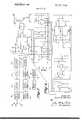
- FIG. 6is a schematic view of the electrical circuitry of this invention.
- the numeral 10generally designates a fixed wrist-hand splint of this invention which is adapted to be secured to the patients lower arm, wrist and hand.
- Splint 10includes a splint portion 12 which is secured to the patients arm 14 by a strap 16 extending therearound and selectively closed by a Velcro fastener means 18 (FIG. I).
- the upper end of splint portion 20is pivotally connected to the lower end of splint portion 12 by a pin 22.
- Thumb support 24extends downwardly from one end of splint portion 20 and is adapted to have the patient's thumb received therein (FIG. I).
- a curved support 26is pivotally secured at its upper end to splint portion 20 by a pin 28 and has spaced-apart, finger supports 30 and 32 extending laterally therefrom.
- finger support 30is adapted to have the patients fingers extending therethrough while finger support 32 is adapted to extend over the patient's fingers.
- An arcuate hand support 34is secured to splint portion 20 and extends laterally therefrom adapted to cup or support the underside of the patients hand. Strap 36 extends around the patients hand to firmly maintain the device thereon.
- a hydraulic actuator 38is secured to splint portion 20 by bracket 40 and has a push rod 42 slidably extending therefrom which is pivotally secured by a pin 44 to one ofthe adjustment holes 46 formed in ear 48 which extends from the rearward end of support 26.
- extension of push rod 42 from the hydraulic actuator 38causes support 26 to pivot towards thumb support 24.
- withdrawal of push rod 42 into the actuator 38causes support 26 to pivot away from the thumb support 24.
- Hydraulic actuator 38includes a piston head portion 50 secured to cylinder housing 52 by head screws 54.
- a bellowfram 56is positioned between piston head portion SI) and cylinder housing 52 as seen in FIG. 3.
- a U-shaped piston 58is secured to bellowfram 56 by a piston cap screw 60 extending through piston cap 62, bellowfram 56 and into piston 58.
- Push rod 42is secured to piston 58 and extends through spaced apart ball bushings 64 and 66 to reduce friction.
- a helical compression spring 68embraces push rod 42 between piston 58 and support 70 and yieldably resists the extension of push rod 42 from housing 52.
- Nipple 72extends from piston head portion 50 and is adapted to have a fluid line 74 connected thereto to place the fluid chamber 76 in actuator 38 in communication with pump 78.
- Pump 78includes a hollow piston head 80 having a nipple 82 extending therefrom adapted to receive the fluid line 74 thereon.
- Pump 78includes a fluid chamber 84 having a pressure transducer 86 extending thereinto. Pressure transducer 86 is provided with an electrical lead 88 which extends to a differential amplifier which will be discussed hereinafter.
- a bellowfram 90is positioned between piston head 80 and cylinder housing 92 by means of cap screws 94.
- a U-shaped piston 96is secured to the center of bellowfram 90 by cap screws 98 extending through cap 100, bellowfram 90 and into piston 96.
- piston 96has an end plate 104 secured thereto which bears against the ball bearing screw nut I02 which runs in a groove of a grooved helical screw I16.
- Screw 116is secured to the drive shaft I05 which rotatably extends from a battery operated, direct current motor 106.
- the numeral 108refers to a coupling housing positioned between motor I06 and housing 92 and maintained therebetween by screws 110.
- An oldham coupling 120connects motor 106 to screw 116.
- Energization of the motor 106causes power shaft to rotate ball bearing screw 116.
- the rotation of screw I16causes screw nut 102 to be moved along the groove of the screw I16 to cause spring I18 to drive piston 96 to the right as viewed in FIG. 4.
- Movement of piston 96 to the rightcauses the fluid in chamber 84 to be forced therefrom, through line 74 and into the fluid compartment of actuator 38.
- the fluid entering fluid compartment 76 in actuator 38causes piston 58 to be moved to the left, as viewed in FIG. 3, which causes push rod 42 to be extended from the actuator 38 which in turn causes support 26, and hence the patients fingers, to be moved towards the thumb support 24.
- the numerals I12, I14 and 116refer to the skin electrodes which are placed adjacent the skin surface of the patients arm as indicated in FIG. I and maintained thereon by suitable means such as tape or the like.
- the electrodesare connected to a muscle potential amplifier generally referred to by the reference numeral 118 in FIGS. 5 and 6. If the patient desires to close his fingers, he tenses a muscle located near the skin surface electrodes. The resulting muscle potentials are then amplified by the muscle potential amplifier 118.
- This amplifier FIG. 6,consists ofa pair of operational amplifiers in a unity gain to common mode type circuit followed by a differential amplifier circuit, a parallel T" rejection filter circuit, and a Darlington amplifier circuit.
- the amplified myopotentialsare then put into a detector circuit 120, consisting of a Schmidt trigger circuit followed by a low-pass filter circuit.
- This detector circuittransforms the amplified muscle potentials into a slowly varying control signal whose amplitude is related to the muscle tension causing it.
- the motor control circuit 126causes the motor 106 to drive the hydraulic pump 78 until a pressure related to the desired finger position plus tension is reached.
- the motor control circuitcontains two identical control circuits consisting of a relaxation oscillator circuit which drives a hybrid timing circuit and a transistor bridge circuit. In this way both clockwise and counterclockwise rotation can be obtained depending upon which control circuit drives the transistor bridge circuit.
- the motor W6stops when the signal from the pressure transducer 86 causes the differential amplifier B24 output signal to go below a set threshold level. If the patient wishes to open his fingers, he simply relaxes and the signal from the pressure transducer 86 causes the motor 106 to reduce the pressure so that the brace is driven to its zero muscle voltage position by the spring 68 contained in the actuator 33.
- the myoelectric braceis driven by muscle potentials.
- the muscle potentialsare created by tensing or contracting of the muscle which causes polarization of the muscle.
- the electrodes on the skindetect the E.M.G. differential and relays the same to the circuitry illustratcd in the drawings.
- the pump 78 and actuator 38are especially designed to reduce friction through the use of the ball bushings 64 and 66 and through the use of the foldable bellowfram incorporated therein.
- a bracehas been provided which is lightweight and which requires a minimum of power to be consumed during the operation thereof.
- the size of the braceis relatively small and is conveniently secured to the patients arm. Finger position and lietlSlOtt is controlled in a proportional manner due to the muscle potentials being sensed by the surface electrodes and the relationship of the pressure transducer to the motor control circuit,
- a splint meansadapted to be secured to a person's arm and having a fixed wrist-hand splint portion and a movable finger support means pivotally connected thereto,
- a hydraulic actuator meansmounted on said fixed wristband splint portion and being connected to said movable finger support means to cause said finger support means to be moved with respect to said fixed splint portion
- a hydraulic pump meansfluidly connected to said actuator means adapted to cause said actuator means to move said finger support means
- an electrode meansadapted to be placed on the wearer's skin surface adjacent a muscle capable of being tensed by the wearer
- circuit meansconnected to said electrode means adapted to sense the myopotentials created by the tensing of said muscle and to transform the potentials into a control signal whereby said electric motor, said pump and said actuator will be operated so that said finger support means will be moved towards said fixed splint means, and
- said pump meansincluding a hollow piston head housing having a fluid compartment provided therein, said fluid compartment being in fluid communication with said actuator means, a cylinder housing connected to said piston head housing, a bellowfram between said piston head housing and said cylinder housing, a piston means in said cylinder housing connected to said bellowfram for movement therewith, a ball bearing screw rotatably mounted in said cylinder housing, a screw nut operatively connected to said piston means in engagement with said screw whereby rotation of said screw will cause said piston and said bellowfram to be moved, said motor having a drive shaft connected to said screw.
- a pressure transduceris in communication with said fluid compartment in said piston head housing, said pressure transducer being electrically connected to said circuit means to stop said motor when a predetermined pressure is reached in said fluid compartment.
Landscapes
- Health & Medical Sciences (AREA)
- Engineering & Computer Science (AREA)
- Life Sciences & Earth Sciences (AREA)
- Animal Behavior & Ethology (AREA)
- Veterinary Medicine (AREA)
- Biomedical Technology (AREA)
- Heart & Thoracic Surgery (AREA)
- Vascular Medicine (AREA)
- Public Health (AREA)
- General Health & Medical Sciences (AREA)
- Transplantation (AREA)
- Cardiology (AREA)
- Oral & Maxillofacial Surgery (AREA)
- Nursing (AREA)
- Orthopedic Medicine & Surgery (AREA)
- Robotics (AREA)
- Mechanical Engineering (AREA)
- Prostheses (AREA)
Abstract
Description
United States Patent [72] Inventor Allan G. Potter Ames, Iowa [21] Appl. No. 848,919
[22] Filed Aug. 11, 1969 [45] Patented Jan. 4, 1972 [73] Assignee Iowa State University Research Foundation Ames, Iowa [54] MYOELECTRIC BRACE Myo-Electric Control of Powered Prostheses by A. H. Bottomley, The Journal of Bone & Joint Surgery, Vol. 47B, No.3,Aug.1965,pp.411-415,3-1.1
Gas-Powered Sources and Actuators for Prosthetic and Orthotic Devices" by J. R. Pearson, The Control of External Power in Upper-Extremity Rehabilitation, Nat. Academy of Sciences- Nat. Research Council, Wash., DC, 1966, pp. 196-197 (FIG. 5) copy in P.O. Scientific Library (RD756- N32C). 3-1.2
Myoelectric Control Systems" by W. Waring et al.,
Orthopedic & Prosthetic Appl. Journal, Vol. 21, No. 1, Mar. 1967, pp. 27-32. 3l.l
Myo-Electrically Controlled Electric Torque Motor for the Flexor Hinge Hand Splint by C. 'Irombley et al., Orthopedic & Prosthetic Appliance Journal, Vol. 21, No. 1, Mar. 1967, pp. 39-43. 3-1.1
Primary ExaminerRichard A. Gaudet Assistant Examiner-Ronald L. F rinks Attorney-Zarley, McKee & Thomte ABSTRACT: A myoelectric brace consisting of a fixed wristband splint portion having a movable finger support portion pivotally secured thereto which is operated by a hydraulic actuator. The actuator is hydraulically coupled to a pump which is driven by a battery powered, direct current motor. Three skin electrodes are positioned on the patients arm and sense muscle potentials in the patients arm when the patient tenses a muscle in the immediate area of the skin electrodes. The resulting myo-potentials are then amplified by a muscle potential amplifier and are transformed into a slowly varying control signal by a detector circuit and a filter circuit. The control signal enters a differential amplifier where it causes the motor to drive the hydraulic pump until a predetermined pressure is reached. Actuation of the hydraulic pump causes the hydraulic actuator to pivotally move the finger support towards the fixed splint portion. The motor stops when the differential amplifier receives a signal from the pressure transducer equal in amplitude to the control signal. This causes the differential amplifier output signal to go to zero. Relaxation of the patients muscle causes the finger support to pivotally move away from the fixed splint portion.
PATENTEDJAN 41912 3531.542
SHEET 1 [IF 2 Arrow/945 MYOELECTRIC BRACE Electrically powered orthotic devices or braces for quadraplegic patients are convenient because the electrical power is readily available and is easily stored in the batteries which drive the electric motors on wheel chairs used by such patients. The utilization of other types of energy storage techniques by these patients requires the handling of another source of energy and thus, another set of operating conditions which is highly undesirable. In order to utilize the electrical energy stored in the wheel chair batteries to effectively power orthotic devices, one must optimize several conflicting requirements. First, both the weight and size of the bracemounted actuator must be small. Second, the response and control of the limb brace when driven by the actuator must be normal. Third, minimum size, weight, and power consumption is desired for the complete device.
Therefore, it is a principal object of this invention to pro vide a myoelectric brace for quadraplegic patients.
A further object of this invention is to provide a myoelectric brace which is powered by a unique hydraulic system driven by a direct current battery operated motor.
A further object of this invention is to provide a myoelectric brace which is light weight.
A further object of this invention is to provide a myoelectric brace which has a minimum size and consumes a minimum of power.
A further object of this invention is to provide a myoelectric brace which is operated by the muscle potentials in the patients arm.
A further object of this invention is to provide a myoelectric brace wherein muscle potentials are sensed by surface electrodes and are used to control finger position and tension in a proportional manner.
A further object of this invention is to provide a method of actuating a myoelectric brace.
A further object of this invention is to provide a myoelectric brace which is economical of manufacture, durable in use and refined in appearance.
These and other objects will be apparent to those skilled in the art.
This invention consists in the construction, arrangements, and combination of the various parts of the device, whereby the objects contemplated are attained as hereinafter more fully set forth, specifically pointed out in the claims, and illustrated in the accompanying drawings in which:
FIG. I is a side elevational view of the brace mounted on the patients arm;
FIG. 2 is a top view of the brace as seen alonglines 22 of FIG. I;
FIG. 3 is a longitudinal sectional view of the hydraulic actuator as seen along lines 3-3 of FIG. 1;
FIG. 4 is a fragmentary longitudinal sectional view of the hydraulic pump as seen along lines 4-4 of FIG. 1;
FIG. 5 is a block diagram of the electrical circuitry of this invention; and
FIG. 6 is a schematic view of the electrical circuitry of this invention.
The numeral 10 generally designates a fixed wrist-hand splint of this invention which is adapted to be secured to the patients lower arm, wrist and hand. Splint 10 includes asplint portion 12 which is secured to thepatients arm 14 by astrap 16 extending therearound and selectively closed by a Velcro fastener means 18 (FIG. I). The upper end of splint portion 20 is pivotally connected to the lower end ofsplint portion 12 by apin 22.Thumb support 24 extends downwardly from one end of splint portion 20 and is adapted to have the patient's thumb received therein (FIG. I). Acurved support 26 is pivotally secured at its upper end to splint portion 20 by apin 28 and has spaced-apart, finger supports 30 and 32 extending laterally therefrom. As seen in FIG. I,finger support 30 is adapted to have the patients fingers extending therethrough whilefinger support 32 is adapted to extend over the patient's fingers. An arcuate hand support 34 is secured to splint portion 20 and extends laterally therefrom adapted to cup or support the underside of the patients hand.Strap 36 extends around the patients hand to firmly maintain the device thereon.
Ahydraulic actuator 38 is secured to splint portion 20 bybracket 40 and has apush rod 42 slidably extending therefrom which is pivotally secured by apin 44 to one ofthe adjustment holes 46 formed inear 48 which extends from the rearward end ofsupport 26. Thus, extension ofpush rod 42 from thehydraulic actuator 38 causessupport 26 to pivot towardsthumb support 24. Conversely, the withdrawal ofpush rod 42 into theactuator 38 causes support 26 to pivot away from thethumb support 24.
Pushrod 42 is secured topiston 58 and extends through spaced apartball bushings helical compression spring 68 embracespush rod 42 betweenpiston 58 andsupport 70 and yieldably resists the extension ofpush rod 42 from housing 52.Nipple 72 extends from piston head portion 50 and is adapted to have afluid line 74 connected thereto to place thefluid chamber 76 inactuator 38 in communication withpump 78.Pump 78 includes ahollow piston head 80 having anipple 82 extending therefrom adapted to receive thefluid line 74 thereon.Pump 78 includes afluid chamber 84 having apressure transducer 86 extending thereinto.Pressure transducer 86 is provided with anelectrical lead 88 which extends to a differential amplifier which will be discussed hereinafter.
Abellowfram 90 is positioned betweenpiston head 80 andcylinder housing 92 by means of cap screws 94. AU-shaped piston 96 is secured to the center ofbellowfram 90 bycap screws 98 extending throughcap 100,bellowfram 90 and intopiston 96.
The other end ofpiston 96 has anend plate 104 secured thereto which bears against the ball bearing screw nut I02 which runs in a groove of a grooved helical screw I16.Screw 116 is secured to the drive shaft I05 which rotatably extends from a battery operated, directcurrent motor 106. The numeral 108 refers to a coupling housing positioned between motor I06 andhousing 92 and maintained therebetween byscrews 110. Anoldham coupling 120 connectsmotor 106 to screw 116.
Energization of themotor 106 causes power shaft to rotateball bearing screw 116. The rotation of screw I16 causes screwnut 102 to be moved along the groove of the screw I16 to cause spring I18 to drivepiston 96 to the right as viewed in FIG. 4. Movement ofpiston 96 to the right causes the fluid inchamber 84 to be forced therefrom, throughline 74 and into the fluid compartment ofactuator 38. The fluid enteringfluid compartment 76 inactuator 38causes piston 58 to be moved to the left, as viewed in FIG. 3, which causespush rod 42 to be extended from theactuator 38 which in turn causessupport 26, and hence the patients fingers, to be moved towards thethumb support 24.
The numerals I12, I14 and 116 refer to the skin electrodes which are placed adjacent the skin surface of the patients arm as indicated in FIG. I and maintained thereon by suitable means such as tape or the like. The electrodes are connected to a muscle potential amplifier generally referred to by thereference numeral 118 in FIGS. 5 and 6. If the patient desires to close his fingers, he tenses a muscle located near the skin surface electrodes. The resulting muscle potentials are then amplified by the musclepotential amplifier 118. This amplifier FIG. 6, consists ofa pair of operational amplifiers in a unity gain to common mode type circuit followed by a differential amplifier circuit, a parallel T" rejection filter circuit, and a Darlington amplifier circuit. The amplified myopotentials are then put into adetector circuit 120, consisting of a Schmidt trigger circuit followed by a low-pass filter circuit. This detector circuit transforms the amplified muscle potentials into a slowly varying control signal whose amplitude is related to the muscle tension causing it. if the output of the differential amplificr T24 is sufficiently large themotor control circuit 126 causes themotor 106 to drive thehydraulic pump 78 until a pressure related to the desired finger position plus tension is reached. The motor control circuit contains two identical control circuits consisting of a relaxation oscillator circuit which drives a hybrid timing circuit and a transistor bridge circuit. In this way both clockwise and counterclockwise rotation can be obtained depending upon which control circuit drives the transistor bridge circuit. The motor W6 stops when the signal from thepressure transducer 86 causes the differential amplifier B24 output signal to go below a set threshold level. If the patient wishes to open his fingers, he simply relaxes and the signal from thepressure transducer 86 causes themotor 106 to reduce the pressure so that the brace is driven to its zero muscle voltage position by thespring 68 contained in the actuator 33.
In summary, it can be seen that the myoelectric brace is driven by muscle potentials. The muscle potentials are created by tensing or contracting of the muscle which causes polarization of the muscle. The electrodes on the skin detect the E.M.G. differential and relays the same to the circuitry illustratcd in the drawings. Thepump 78 andactuator 38 are especially designed to reduce friction through the use of theball bushings
A brace has been provided which is lightweight and which requires a minimum of power to be consumed during the operation thereof. The size of the brace is relatively small and is conveniently secured to the patients arm. Finger position and lietlSlOtt is controlled in a proportional manner due to the muscle potentials being sensed by the surface electrodes and the relationship of the pressure transducer to the motor control circuit,
Thus it can be seen that the device accomplishes at least all ofits stated objectivesv lclaim:
l. in a myoelectric brace, comprising,
a splint means adapted to be secured to a person's arm and having a fixed wrist-hand splint portion and a movable finger support means pivotally connected thereto,
a hydraulic actuator means mounted on said fixed wristband splint portion and being connected to said movable finger support means to cause said finger support means to be moved with respect to said fixed splint portion,
a hydraulic pump means fluidly connected to said actuator means adapted to cause said actuator means to move said finger support means,
a motor means for operating said pump means,
an electrode means adapted to be placed on the wearer's skin surface adjacent a muscle capable of being tensed by the wearer,
a circuit means connected to said electrode means adapted to sense the myopotentials created by the tensing of said muscle and to transform the potentials into a control signal whereby said electric motor, said pump and said actuator will be operated so that said finger support means will be moved towards said fixed splint means, and
said pump means including a hollow piston head housing having a fluid compartment provided therein, said fluid compartment being in fluid communication with said actuator means, a cylinder housing connected to said piston head housing, a bellowfram between said piston head housing and said cylinder housing, a piston means in said cylinder housing connected to said bellowfram for movement therewith, a ball bearing screw rotatably mounted in said cylinder housing, a screw nut operatively connected to said piston means in engagement with said screw whereby rotation of said screw will cause said piston and said bellowfram to be moved, said motor having a drive shaft connected to said screw. I 2. The brace ofclaim 1 wherein a pressure transducer is in communication with said fluid compartment in said piston head housing, said pressure transducer being electrically connected to said circuit means to stop said motor when a predetermined pressure is reached in said fluid compartment.
Claims (2)
1. In a myoelectric brace, comprising, a splint means adapted to be secured to a person''s arm and having a fixed wrist-hand splint portion and a movable finger support means pivotally connected thereto, a hydraulic actuator means mounted on said fixed wrist-hand splint portion and being connected to said movable finger support means to cause said finger support means to be moved with respect to said fixed splint portion, a hydraulic pump means fluidly connected to said actuator means adapted to cause said actuator means to move said finger support means, a motor means for operating said pump means, an electrode means adapted to be placed on the wearer''s skin surface adjacent a muscle capable of being tensed by the wearer, a circuit means connected to said electrode means adapted to sense the myo-potentials created by the tensing of said muscle and to transform the potentials into a control signal whereby said electric motor, said pump and said actuator will be operated so that said finger support means will be moved towards said fixed splint means, and said pump means including a hollow piston head housing having a fluid compartment provided therein, said fluid compartment being in fluid communication with said actuator means, a cylinder housing connected to said piston head housing, a bellowfram between said piston head housing and said cylinder housing, a piston means in said cylinder housing connected to said bellowfram for movement therewith, a ball bearing screw rotatably mounted in said cylinder housing, a screw nut operatively connected to said piston means in engagement with said screw whereby rotation of said screw will cause said piston and said bellowfram to be moved, said motor having a drive shaft connected to said screw.
2. The brace of claim 1 wherein a pressure transducer is in communication with said fluid compartment in said piston head housing, said pressure transducer being electrically connected to said circuit means to stop said motor when a predetermined pressure is reached in said fluid compartment.
Applications Claiming Priority (1)
| Application Number | Priority Date | Filing Date | Title |
|---|---|---|---|
| US84891969A | 1969-08-11 | 1969-08-11 |
Publications (1)
| Publication Number | Publication Date |
|---|---|
| US3631542Atrue US3631542A (en) | 1972-01-04 |
Family
ID=25304621
Family Applications (1)
| Application Number | Title | Priority Date | Filing Date |
|---|---|---|---|
| US848919AExpired - LifetimeUS3631542A (en) | 1969-08-11 | 1969-08-11 | Myoelectric brace |
Country Status (1)
| Country | Link |
|---|---|
| US (1) | US3631542A (en) |
Cited By (103)
| Publication number | Priority date | Publication date | Assignee | Title |
|---|---|---|---|---|
| US3735425A (en)* | 1971-02-10 | 1973-05-29 | Us Of America The Secretary Of | Myoelectrically controlled prothesis |
| US4016607A (en)* | 1976-07-30 | 1977-04-12 | Eino Pihlaja | Artificial hand |
| US4259806A (en)* | 1980-06-20 | 1981-04-07 | Summit Licensing Company | Walking toy |
| US4340371A (en)* | 1981-03-18 | 1982-07-20 | The United States Of America As Represented By The Secretary Of The Air Force | Upper and lower arm load simulator |
| WO1983002249A1 (en)* | 1981-12-24 | 1983-07-07 | Hans Richter | Mounting robot |
| WO1987001082A1 (en)* | 1985-08-13 | 1987-02-26 | Martin Werder | Cross-country vehicle |
| US4679548A (en)* | 1984-02-01 | 1987-07-14 | Compagnie Generale De Material Orthopedique | Re-education apparatus for the articulated segments of the hand |
| USD294176S (en) | 1985-08-13 | 1988-02-09 | Tyo Diane M | Wrist orthosis for use in radial nerve palsy |
| US4724827A (en)* | 1985-01-10 | 1988-02-16 | Schenck Robert R | Dynamic traction device |
| US4782825A (en)* | 1987-05-21 | 1988-11-08 | Robert Lonardo | Combination arm splint and finger support means |
| US4792338A (en)* | 1985-10-15 | 1988-12-20 | Centri Gummifabrik Ab | Artificial hand |
| US4875469A (en)* | 1988-06-13 | 1989-10-24 | Innovative Medical Engineering, Inc. | Continuous passive motion devices and methods |
| USRE33182E (en)* | 1984-01-02 | 1990-03-20 | Compagnie Generale De Materiel Orthopedique | Re-education apparatus for the articulated segments of the hand |
| US5103811A (en)* | 1990-07-09 | 1992-04-14 | Crupi Jr Theodore P | Body part or joint brace |
| US5147285A (en)* | 1991-08-01 | 1992-09-15 | Buxton Aldene H | Movable thumb brace |
| US5222986A (en)* | 1992-01-27 | 1993-06-29 | Wright Donald M | Hand prosthesis for grasping large and small objects |
| US5252102A (en)* | 1989-01-24 | 1993-10-12 | Electrobionics Corporation | Electronic range of motion apparatus, for orthosis, prosthesis, and CPM machine |
| US5376091A (en)* | 1990-06-08 | 1994-12-27 | Smith & Nephew Richards, Inc. | Dynamic finger support |
| EP0650708A1 (en)* | 1992-10-13 | 1995-05-03 | Carl Anthony Caspers | Prosthetic liner and method of making the liner with a prosthesis socket |
| AU660309B2 (en)* | 1991-05-06 | 1995-06-22 | Smith & Nephew, Inc. | Dynamic joint support |
| US5458560A (en)* | 1993-09-03 | 1995-10-17 | Jace Systems, Inc. | Continuous passive motion device for a wrist |
| US5549709A (en)* | 1995-07-26 | 1996-08-27 | Caspers; Carl A. | Hypobarically-Controlled artificial limb for amputees |
| US5653680A (en)* | 1995-08-10 | 1997-08-05 | Cruz; Mark K. | Active wrist brace |
| US5683351A (en)* | 1994-09-27 | 1997-11-04 | Jace Systems, Inc. | Continuous passive motion device for a hand |
| US5707345A (en)* | 1992-12-14 | 1998-01-13 | Para Tech Industries, Inc. | Method for treating carpal tunnel syndrome |
| US5735906A (en)* | 1995-07-26 | 1998-04-07 | Caspers; Carl A. | Hypobarically-controlled artificial limb with detents for amputees |
| US5800561A (en)* | 1996-05-15 | 1998-09-01 | Massachusetts Institute Of Technology | Power-assisted upper extremity orthosis |
| USD404818S (en)* | 1997-10-14 | 1999-01-26 | Mark Cruz | Combination orthosis for the elbow and wrist joints |
| US6080123A (en)* | 1998-09-14 | 2000-06-27 | Pansiera; Timothy Thomas | Orthotic joint with radial hydraulic force transfer |
| USD429335S (en)* | 1999-09-03 | 2000-08-08 | Caspers-Schneider Technologies, Inc. | Prosthetic liner reinforcement patch |
| US6179799B1 (en) | 1999-02-01 | 2001-01-30 | Robert E. Doran | Orthosis for supination and pronation of the wrist |
| US6508842B1 (en) | 1999-06-03 | 2003-01-21 | Barbara J. Caspers | Socket liner for artificial limb |
| US6554868B1 (en) | 1999-06-03 | 2003-04-29 | Carl A. Caspers | Vacuum pump and shock absorber for artificial limb |
| US6645253B2 (en) | 1999-06-03 | 2003-11-11 | Carl A. Caspers | Vacuum pump and shock absorber for artificial limb |
| US6689074B2 (en)* | 2000-03-28 | 2004-02-10 | Seiko Epson Corporation | Wearable muscular-force supplementing device |
| US20040030411A1 (en)* | 1999-06-03 | 2004-02-12 | Caspers Carl A. | Pulsating pressure chamber and method for fluid management |
| WO2004019834A1 (en)* | 2002-08-21 | 2004-03-11 | Technische Universität Berlin | Device for influencing movement with a parallel mechanism |
| US6726726B2 (en) | 1999-06-03 | 2004-04-27 | Otto Bock Healthcare Lp | Vacuum apparatus and method for managing residual limb volume in an artificial limb |
| US20040102723A1 (en)* | 2002-11-25 | 2004-05-27 | Horst Robert W. | Active muscle assistance device and method |
| US20040106881A1 (en)* | 2002-11-21 | 2004-06-03 | Mcbean John M. | Powered orthotic device |
| US20040143345A1 (en)* | 1999-06-03 | 2004-07-22 | Barbara Caspers | Socket liner for artificial limb |
| US6926742B2 (en) | 1999-06-03 | 2005-08-09 | Otto Bock Healthcare Lp | Plate/socket attachment for artificial limb vacuum pump |
| US20050245853A1 (en)* | 2002-04-16 | 2005-11-03 | Scorvo Sean K | Adjustable orthotic brace |
| US20050273027A1 (en)* | 2002-02-25 | 2005-12-08 | Saebo, Inc. | Dynamic hand splint |
| US6974484B2 (en) | 1999-06-03 | 2005-12-13 | Otto Bock Healthcare Lp | Osmotic membrane and vacuum system for artificial limb |
| US20060211964A1 (en)* | 2004-12-10 | 2006-09-21 | Saebo, Inc. | Dynamic hand splints |
| US20070155557A1 (en)* | 2005-12-30 | 2007-07-05 | Horst Robert W | Deflector assembly |
| US20070265711A1 (en)* | 2006-05-09 | 2007-11-15 | Otto Bock Healthcare Products Gmbh | Internal socket and fitting system for a prosthesis |
| US20080071386A1 (en)* | 2006-09-19 | 2008-03-20 | Myomo, Inc. | Powered Orthotic Device and Method of Using Same |
| US20080195005A1 (en)* | 2007-02-14 | 2008-08-14 | Horst Robert W | Methods and devices for deep vein thrombosis prevention |
| CN100427047C (en)* | 2006-06-14 | 2008-10-22 | 吉林大学 | Medical automatic constant force small splint |
| US20080277943A1 (en)* | 2005-08-10 | 2008-11-13 | Donelan James M | Method and apparatus for harvesting biomechanical energy |
| US20090099492A1 (en)* | 2007-10-11 | 2009-04-16 | Saebo, Inc. | Splint assembly for positioning of the hand |
| WO2006072068A3 (en)* | 2004-12-30 | 2009-04-23 | Saebo Inc | Dynamic splint assembly |
| US20090204038A1 (en)* | 2008-02-08 | 2009-08-13 | Tibion Corporation | Multi-fit orthotic and mobility assistance apparatus |
| US20090227925A1 (en)* | 2006-09-19 | 2009-09-10 | Mcbean John M | Powered Orthotic Device and Method of Using Same |
| US20090306548A1 (en)* | 2008-06-05 | 2009-12-10 | Bhugra Kern S | Therapeutic method and device for rehabilitation |
| US20100038983A1 (en)* | 2008-08-14 | 2010-02-18 | Kern Bhugra | Actuator system with a motor assembly and latch for extending and flexing a joint |
| US20100039052A1 (en)* | 2008-08-14 | 2010-02-18 | Horst Robert W | Actuator system with a multi-motor assembly for extending and flexing a joint |
| US20100204620A1 (en)* | 2009-02-09 | 2010-08-12 | Smith Jonathan A | Therapy and mobility assistance system |
| WO2010117065A1 (en)* | 2009-04-09 | 2010-10-14 | 国立大学法人筑波大学 | Wearable motion assist device |
| US20100280423A1 (en)* | 2007-12-28 | 2010-11-04 | Panasonic Corporation | Muscle force assisting device (as amended) |
| US20110004322A1 (en)* | 2005-01-26 | 2011-01-06 | University Of Tsukuba | Wearable action-assist device and control program |
| US8016780B1 (en)* | 2009-01-02 | 2011-09-13 | George Sickles | Orthopedic brace |
| US20110282253A1 (en)* | 2009-09-21 | 2011-11-17 | Carlo Menon | Wrist exoskeleton |
| US20120101596A1 (en)* | 2009-06-23 | 2012-04-26 | Otto Bock Healthcare Products Gmbh | Method for setting up a control and technical orthopedic device |
| CN102848384A (en)* | 2012-10-08 | 2013-01-02 | 常州汉迪机器人科技有限公司 | Flexible actuator of robot system and robot system |
| CN103112005A (en)* | 2011-11-17 | 2013-05-22 | 财团法人精密机械研究发展中心 | Gesture type mechanical arm |
| US8496715B2 (en) | 2007-04-27 | 2013-07-30 | Otto Bock Healthcare Lp | Pneumatic connections for prosthetic socket |
| CN103315737A (en)* | 2013-06-18 | 2013-09-25 | 上海交通大学 | Wearable multi-channel surface electromyogram signal collecting armlet |
| US8591599B1 (en)* | 2011-01-07 | 2013-11-26 | Infinite Biomedical Technologies, Llc | Electrode assemblies for detecting muscle signals in a prosthetic liner |
| US8639455B2 (en) | 2009-02-09 | 2014-01-28 | Alterg, Inc. | Foot pad device and method of obtaining weight data |
| US8736087B2 (en) | 2011-09-01 | 2014-05-27 | Bionic Power Inc. | Methods and apparatus for control of biomechanical energy harvesting |
| US20140243721A1 (en)* | 2013-02-28 | 2014-08-28 | Marvin Frank Bryant | Myoelectric hand orthosis |
| EP2868304A1 (en)* | 2013-11-01 | 2015-05-06 | John Abramowicz | System for promoting elongation and relaxation of muscles |
| US9044348B2 (en) | 2012-04-30 | 2015-06-02 | Ossur Hf | Prosthetic device, system and method for increasing vacuum attachment |
| US9198780B2 (en) | 2012-02-14 | 2015-12-01 | Ossur Hf | Vacuum assisted suspension system |
| US9364348B2 (en) | 2013-03-01 | 2016-06-14 | Ossur Hf | Vacuum suspension system |
| US20160221181A1 (en)* | 2015-01-29 | 2016-08-04 | Airbus Operations Gmbh | Support device for stabilizing a body part of a person |
| EP3146944A1 (en)* | 2015-09-23 | 2017-03-29 | Albrecht GmbH | Wrist orthotic |
| US9757256B2 (en) | 2014-07-01 | 2017-09-12 | Ossur Hf | Pump mechanism for vacuum suspension system |
| US9757266B2 (en) | 2010-06-01 | 2017-09-12 | Saebo, Inc. | Orthotic device |
| US9764190B2 (en) | 2012-06-13 | 2017-09-19 | Saebo, Inc. | Dynamic hand splints |
| US9889058B2 (en) | 2013-03-15 | 2018-02-13 | Alterg, Inc. | Orthotic device drive system and method |
| US9943421B2 (en) | 2015-05-21 | 2018-04-17 | Ossur Iceland Ehf | Membrane pump system for use with a prosthetic system |
| US10028845B2 (en) | 2015-01-08 | 2018-07-24 | Ossur Iceland Ehf | Pump mechanism |
| WO2018158554A3 (en)* | 2017-02-28 | 2018-10-25 | Ambionics International Limited | Prosthetic limb |
| US10179055B2 (en) | 2015-05-29 | 2019-01-15 | Ossur Iceland Ehf | Pump system for use with a prosthetic device |
| US10195099B2 (en) | 2016-01-11 | 2019-02-05 | Bionic Power Inc. | Method and system for intermittently assisting body motion |
| US10245204B2 (en) | 2015-09-11 | 2019-04-02 | Ekso Bionics, Inc. | Devices and methods for improving the utility of an exoskeleton mobility base |
| US10413429B2 (en) | 2015-08-27 | 2019-09-17 | Ossur Iceland Ehf | Pump system |
| US10512554B2 (en) | 2016-08-26 | 2019-12-24 | Ossur Iceland Ehf | Pump system |
| WO2019234707A3 (en)* | 2018-06-08 | 2020-04-09 | Epic Inventing, Inc. | Prosthetic hand |
| US10758379B2 (en) | 2016-05-25 | 2020-09-01 | Scott MANDELBAUM | Systems and methods for fine motor control of fingers on a prosthetic hand to emulate a natural stroke |
| US10758394B2 (en) | 2006-09-19 | 2020-09-01 | Myomo, Inc. | Powered orthotic device and method of using same |
| EP3698765A4 (en)* | 2017-10-20 | 2020-12-23 | Panasonic Corporation | FINGER DRIVE DEVICE |
| US10912667B1 (en) | 2017-01-27 | 2021-02-09 | George Sickles | Orthopedic brace |
| CN113397779A (en)* | 2015-06-15 | 2021-09-17 | 我自己的动作有限公司 | Powered orthotic device |
| US11140969B2 (en)* | 2016-11-09 | 2021-10-12 | Randall Alley | Load distribution systems and load carrying equipment |
| US11357691B2 (en)* | 2016-02-15 | 2022-06-14 | Lime Medical Gmbh | Finger motion rail, support therefor and therapy device comprising same and operating method |
| US11534358B2 (en) | 2019-10-11 | 2022-12-27 | Neurolutions, Inc. | Orthosis systems and rehabilitation of impaired body parts |
| US20230011022A1 (en)* | 2021-07-09 | 2023-01-12 | Kao Chen Enterprise Co., Ltd. | Rehabilitation device |
| US12083063B1 (en) | 2017-01-27 | 2024-09-10 | George Sickles | Orthopedic brace |
- 1969
- 1969-08-11USUS848919Apatent/US3631542A/ennot_activeExpired - Lifetime
Non-Patent Citations (4)
| Title |
|---|
| Gas Powered Sources and Actuators for Prosthetic and Orthotic Devices by J. R. Pearson, The Control of External Power in Upper Extremity Rehabilitation, Nat. Academy of Sciences Nat. Research Council, Wash., D.C., 1966, pp. 196 197 (FIG. 5)* |
| Myo Electric Control of Powered Prostheses by A. H. Bottomley, The Journal of Bone & Joint Surgery, Vol. 47B, No. 3, Aug. 1965, pp. 411 415* |
| Myo Electrically Controlled Electric Torque Motor for the Flexor Hinge Hand Splint by C. Trombley et al., Orthopedic & Prosthetic Appliance Journal, Vol. 21, No. 1, Mar. 1967, pp. 39 43* |
| Myoelectric Control Systems by W. Waring et al., Orthopedic & Prosthetic Appl. Journal, Vol. 21, No. 1, Mar. 1967, pp. 27 32* |
Cited By (187)
| Publication number | Priority date | Publication date | Assignee | Title |
|---|---|---|---|---|
| US3735425A (en)* | 1971-02-10 | 1973-05-29 | Us Of America The Secretary Of | Myoelectrically controlled prothesis |
| US4016607A (en)* | 1976-07-30 | 1977-04-12 | Eino Pihlaja | Artificial hand |
| US4259806A (en)* | 1980-06-20 | 1981-04-07 | Summit Licensing Company | Walking toy |
| US4340371A (en)* | 1981-03-18 | 1982-07-20 | The United States Of America As Represented By The Secretary Of The Air Force | Upper and lower arm load simulator |
| WO1983002249A1 (en)* | 1981-12-24 | 1983-07-07 | Hans Richter | Mounting robot |
| US4575297A (en)* | 1981-12-24 | 1986-03-11 | Hans Richter | Assembly robot |
| USRE33182E (en)* | 1984-01-02 | 1990-03-20 | Compagnie Generale De Materiel Orthopedique | Re-education apparatus for the articulated segments of the hand |
| US4679548A (en)* | 1984-02-01 | 1987-07-14 | Compagnie Generale De Material Orthopedique | Re-education apparatus for the articulated segments of the hand |
| US4724827A (en)* | 1985-01-10 | 1988-02-16 | Schenck Robert R | Dynamic traction device |
| USD294176S (en) | 1985-08-13 | 1988-02-09 | Tyo Diane M | Wrist orthosis for use in radial nerve palsy |
| WO1987001082A1 (en)* | 1985-08-13 | 1987-02-26 | Martin Werder | Cross-country vehicle |
| US4792338A (en)* | 1985-10-15 | 1988-12-20 | Centri Gummifabrik Ab | Artificial hand |
| US4782825A (en)* | 1987-05-21 | 1988-11-08 | Robert Lonardo | Combination arm splint and finger support means |
| US4875469A (en)* | 1988-06-13 | 1989-10-24 | Innovative Medical Engineering, Inc. | Continuous passive motion devices and methods |
| US5252102A (en)* | 1989-01-24 | 1993-10-12 | Electrobionics Corporation | Electronic range of motion apparatus, for orthosis, prosthesis, and CPM machine |
| US5376091A (en)* | 1990-06-08 | 1994-12-27 | Smith & Nephew Richards, Inc. | Dynamic finger support |
| US5103811A (en)* | 1990-07-09 | 1992-04-14 | Crupi Jr Theodore P | Body part or joint brace |
| AU660309B2 (en)* | 1991-05-06 | 1995-06-22 | Smith & Nephew, Inc. | Dynamic joint support |
| US5147285A (en)* | 1991-08-01 | 1992-09-15 | Buxton Aldene H | Movable thumb brace |
| US5222986A (en)* | 1992-01-27 | 1993-06-29 | Wright Donald M | Hand prosthesis for grasping large and small objects |
| EP0650708A1 (en)* | 1992-10-13 | 1995-05-03 | Carl Anthony Caspers | Prosthetic liner and method of making the liner with a prosthesis socket |
| EP1010407A1 (en)* | 1992-10-13 | 2000-06-21 | Carl Anthony Caspers | Prosthetic liner and method of making the liner with a prosthetic socket |
| US5707345A (en)* | 1992-12-14 | 1998-01-13 | Para Tech Industries, Inc. | Method for treating carpal tunnel syndrome |
| US5458560A (en)* | 1993-09-03 | 1995-10-17 | Jace Systems, Inc. | Continuous passive motion device for a wrist |
| US5620410A (en)* | 1993-09-03 | 1997-04-15 | Jace Systems, Inc. | Continuous passive motion device for a wrist |
| US5683351A (en)* | 1994-09-27 | 1997-11-04 | Jace Systems, Inc. | Continuous passive motion device for a hand |
| US5549709A (en)* | 1995-07-26 | 1996-08-27 | Caspers; Carl A. | Hypobarically-Controlled artificial limb for amputees |
| US5735906A (en)* | 1995-07-26 | 1998-04-07 | Caspers; Carl A. | Hypobarically-controlled artificial limb with detents for amputees |
| US5653680A (en)* | 1995-08-10 | 1997-08-05 | Cruz; Mark K. | Active wrist brace |
| US5800561A (en)* | 1996-05-15 | 1998-09-01 | Massachusetts Institute Of Technology | Power-assisted upper extremity orthosis |
| US5904722A (en)* | 1996-06-11 | 1999-05-18 | Caspers; Carl A. | Hypobarically-controlled, double-socket artificial limb with mechanical interlock |
| USD404818S (en)* | 1997-10-14 | 1999-01-26 | Mark Cruz | Combination orthosis for the elbow and wrist joints |
| US6080123A (en)* | 1998-09-14 | 2000-06-27 | Pansiera; Timothy Thomas | Orthotic joint with radial hydraulic force transfer |
| US6179799B1 (en) | 1999-02-01 | 2001-01-30 | Robert E. Doran | Orthosis for supination and pronation of the wrist |
| US6761742B2 (en) | 1999-06-03 | 2004-07-13 | Otto Bock Healthcare Lp | Vacuum pump and shock absorber for artificial limb |
| US6926742B2 (en) | 1999-06-03 | 2005-08-09 | Otto Bock Healthcare Lp | Plate/socket attachment for artificial limb vacuum pump |
| US6554868B1 (en) | 1999-06-03 | 2003-04-29 | Carl A. Caspers | Vacuum pump and shock absorber for artificial limb |
| US6645253B2 (en) | 1999-06-03 | 2003-11-11 | Carl A. Caspers | Vacuum pump and shock absorber for artificial limb |
| US7922775B2 (en) | 1999-06-03 | 2011-04-12 | Otto Bock Healthcare Lp | Pulsating pressure chamber and method for fluid management |
| US20040030411A1 (en)* | 1999-06-03 | 2004-02-12 | Caspers Carl A. | Pulsating pressure chamber and method for fluid management |
| US20110202143A1 (en)* | 1999-06-03 | 2011-08-18 | Otto Bock Healthcare, Lp | Socket liner for artificial limb |
| US6726726B2 (en) | 1999-06-03 | 2004-04-27 | Otto Bock Healthcare Lp | Vacuum apparatus and method for managing residual limb volume in an artificial limb |
| US8758449B2 (en) | 1999-06-03 | 2014-06-24 | Otto Bock Healthcare Lp | Socket liner for artificial limb |
| US6974484B2 (en) | 1999-06-03 | 2005-12-13 | Otto Bock Healthcare Lp | Osmotic membrane and vacuum system for artificial limb |
| US6508842B1 (en) | 1999-06-03 | 2003-01-21 | Barbara J. Caspers | Socket liner for artificial limb |
| US20040143345A1 (en)* | 1999-06-03 | 2004-07-22 | Barbara Caspers | Socket liner for artificial limb |
| US20040181290A1 (en)* | 1999-06-03 | 2004-09-16 | Otto Bock Healthcare Lp | Vacuum apparatus and method for managing residual limb volume in an artificial limb |
| USD429335S (en)* | 1999-09-03 | 2000-08-08 | Caspers-Schneider Technologies, Inc. | Prosthetic liner reinforcement patch |
| US6689074B2 (en)* | 2000-03-28 | 2004-02-10 | Seiko Epson Corporation | Wearable muscular-force supplementing device |
| US8328743B2 (en) | 2002-02-25 | 2012-12-11 | Saebo, Inc. | Dynamic hand splint |
| US20050273027A1 (en)* | 2002-02-25 | 2005-12-08 | Saebo, Inc. | Dynamic hand splint |
| US20090326428A1 (en)* | 2002-02-25 | 2009-12-31 | Saebo, Inc. | Dynamic hand splint |
| US7601130B2 (en) | 2002-02-25 | 2009-10-13 | Saebo, Inc. | Dynamic hand splint |
| US20050245853A1 (en)* | 2002-04-16 | 2005-11-03 | Scorvo Sean K | Adjustable orthotic brace |
| WO2004019834A1 (en)* | 2002-08-21 | 2004-03-11 | Technische Universität Berlin | Device for influencing movement with a parallel mechanism |
| US20040106881A1 (en)* | 2002-11-21 | 2004-06-03 | Mcbean John M. | Powered orthotic device |
| US7396337B2 (en) | 2002-11-21 | 2008-07-08 | Massachusetts Institute Of Technology | Powered orthotic device |
| US20070191743A1 (en)* | 2002-11-21 | 2007-08-16 | Massachusetts Institute Of Technology | Method of Using Powered Orthotic Device |
| US7367958B2 (en) | 2002-11-21 | 2008-05-06 | Massachusetts Institute Of Technology | Method of using powered orthotic device |
| US20060004307A1 (en)* | 2002-11-25 | 2006-01-05 | Horst Robert W | Active muscle assistance device and method |
| US7537573B2 (en) | 2002-11-25 | 2009-05-26 | Tibion Corporation | Active muscle assistance and resistance device and method |
| US6966882B2 (en)* | 2002-11-25 | 2005-11-22 | Tibion Corporation | Active muscle assistance device and method |
| US20100318006A1 (en)* | 2002-11-25 | 2010-12-16 | Horst Robert W | Power regeneration in active muscle assistance device and method |
| US20040102723A1 (en)* | 2002-11-25 | 2004-05-27 | Horst Robert W. | Active muscle assistance device and method |
| US20090036804A1 (en)* | 2002-11-25 | 2009-02-05 | Horst Robert W | Power regeneration in active muscle assistance device and method |
| US8679040B2 (en) | 2002-11-25 | 2014-03-25 | Alterg, Inc. | Intention-based therapy device and method |
| US8328744B2 (en) | 2004-12-10 | 2012-12-11 | Saebo, Inc. | Dynamic hand splints |
| US20110144552A1 (en)* | 2004-12-10 | 2011-06-16 | John Fletcher Farrell | Dynamic hand splints |
| US20060211964A1 (en)* | 2004-12-10 | 2006-09-21 | Saebo, Inc. | Dynamic hand splints |
| US7892194B2 (en) | 2004-12-10 | 2011-02-22 | Saebo, Inc. | Dynamic hand splints |
| WO2006072068A3 (en)* | 2004-12-30 | 2009-04-23 | Saebo Inc | Dynamic splint assembly |
| US8932241B2 (en)* | 2005-01-26 | 2015-01-13 | University Of Tsukuba | Wearable action-assist device and control program |
| US20110004322A1 (en)* | 2005-01-26 | 2011-01-06 | University Of Tsukuba | Wearable action-assist device and control program |
| US9427373B2 (en) | 2005-01-26 | 2016-08-30 | University Of Tsukuba | Wearable action-assist device and control program |
| US7652386B2 (en)* | 2005-08-10 | 2010-01-26 | Bionic Power Inc. | Method and apparatus for harvesting biomechanical energy |
| US7659636B2 (en) | 2005-08-10 | 2010-02-09 | Bionic Power Inc. | Methods and apparatus for harvesting biomechanical energy |
| US8299634B2 (en) | 2005-08-10 | 2012-10-30 | Bionic Power Inc. | Methods and apparatus for harvesting biomechanical energy |
| US9057361B2 (en) | 2005-08-10 | 2015-06-16 | Bionic Power Inc. | Methods and apparatus for harvesting biomechanical energy |
| US8487456B2 (en) | 2005-08-10 | 2013-07-16 | Bionic Power Inc. | Methods and apparatus for harvesting biomechanical energy |
| US20100276944A1 (en)* | 2005-08-10 | 2010-11-04 | Simon Fraser University | Methods and apparatus for harvesting biomechanical energy |
| US20080277943A1 (en)* | 2005-08-10 | 2008-11-13 | Donelan James M | Method and apparatus for harvesting biomechanical energy |
| US7811189B2 (en) | 2005-12-30 | 2010-10-12 | Tibion Corporation | Deflector assembly |
| US20070155557A1 (en)* | 2005-12-30 | 2007-07-05 | Horst Robert W | Deflector assembly |
| US20070265711A1 (en)* | 2006-05-09 | 2007-11-15 | Otto Bock Healthcare Products Gmbh | Internal socket and fitting system for a prosthesis |
| US7670385B2 (en) | 2006-05-09 | 2010-03-02 | Otto Bock Healthcare Gmbh | Internal socket and fitting system for a prosthesis |
| CN100427047C (en)* | 2006-06-14 | 2008-10-22 | 吉林大学 | Medical automatic constant force small splint |
| US8585620B2 (en) | 2006-09-19 | 2013-11-19 | Myomo, Inc. | Powered orthotic device and method of using same |
| US8926534B2 (en) | 2006-09-19 | 2015-01-06 | Myomo, Inc. | Powered orthotic device and method of using same |
| US9398994B2 (en) | 2006-09-19 | 2016-07-26 | Myomo, Inc. | Powered orthotic device and method of using same |
| US20090227925A1 (en)* | 2006-09-19 | 2009-09-10 | Mcbean John M | Powered Orthotic Device and Method of Using Same |
| US20080071386A1 (en)* | 2006-09-19 | 2008-03-20 | Myomo, Inc. | Powered Orthotic Device and Method of Using Same |
| US10758394B2 (en) | 2006-09-19 | 2020-09-01 | Myomo, Inc. | Powered orthotic device and method of using same |
| JP2010504167A (en)* | 2006-09-19 | 2010-02-12 | マイオモ インコーポレイテッド | Power-operated straightening device |
| WO2008036746A3 (en)* | 2006-09-19 | 2008-07-10 | Myomo Inc | Powered orthotic device |
| US8353854B2 (en) | 2007-02-14 | 2013-01-15 | Tibion Corporation | Method and devices for moving a body joint |
| US20080195005A1 (en)* | 2007-02-14 | 2008-08-14 | Horst Robert W | Methods and devices for deep vein thrombosis prevention |
| US9474673B2 (en) | 2007-02-14 | 2016-10-25 | Alterg, Inc. | Methods and devices for deep vein thrombosis prevention |
| US8496715B2 (en) | 2007-04-27 | 2013-07-30 | Otto Bock Healthcare Lp | Pneumatic connections for prosthetic socket |
| US8070702B2 (en) | 2007-10-11 | 2011-12-06 | Saebo, Inc. | Splint assembly for positioning of the hand |
| US8784348B2 (en) | 2007-10-11 | 2014-07-22 | Saebo, Inc. | Splint assembly for positioning of the hand |
| US20090099492A1 (en)* | 2007-10-11 | 2009-04-16 | Saebo, Inc. | Splint assembly for positioning of the hand |
| US20100280423A1 (en)* | 2007-12-28 | 2010-11-04 | Panasonic Corporation | Muscle force assisting device (as amended) |
| US8052629B2 (en) | 2008-02-08 | 2011-11-08 | Tibion Corporation | Multi-fit orthotic and mobility assistance apparatus |
| US20090204038A1 (en)* | 2008-02-08 | 2009-08-13 | Tibion Corporation | Multi-fit orthotic and mobility assistance apparatus |
| US8771210B2 (en) | 2008-02-08 | 2014-07-08 | Alterg, Inc. | Multi-fit orthotic and mobility assistance apparatus |
| US20090306548A1 (en)* | 2008-06-05 | 2009-12-10 | Bhugra Kern S | Therapeutic method and device for rehabilitation |
| US10179078B2 (en) | 2008-06-05 | 2019-01-15 | Alterg, Inc. | Therapeutic method and device for rehabilitation |
| US8058823B2 (en) | 2008-08-14 | 2011-11-15 | Tibion Corporation | Actuator system with a multi-motor assembly for extending and flexing a joint |
| US20100039052A1 (en)* | 2008-08-14 | 2010-02-18 | Horst Robert W | Actuator system with a multi-motor assembly for extending and flexing a joint |
| US20100038983A1 (en)* | 2008-08-14 | 2010-02-18 | Kern Bhugra | Actuator system with a motor assembly and latch for extending and flexing a joint |
| US8274244B2 (en) | 2008-08-14 | 2012-09-25 | Tibion Corporation | Actuator system and method for extending a joint |
| US8016780B1 (en)* | 2009-01-02 | 2011-09-13 | George Sickles | Orthopedic brace |
| US8639455B2 (en) | 2009-02-09 | 2014-01-28 | Alterg, Inc. | Foot pad device and method of obtaining weight data |
| US20100204620A1 (en)* | 2009-02-09 | 2010-08-12 | Smith Jonathan A | Therapy and mobility assistance system |
| US9131873B2 (en) | 2009-02-09 | 2015-09-15 | Alterg, Inc. | Foot pad device and method of obtaining weight data |
| CN102387760A (en)* | 2009-04-09 | 2012-03-21 | 国立大学法人筑波大学 | wearable motion assist device |
| CN102387760B (en)* | 2009-04-09 | 2015-06-10 | 国立大学法人筑波大学 | Wearable motion assistance device |
| US8998831B2 (en) | 2009-04-09 | 2015-04-07 | University Of Tsukuba | Wearable type movement assisting apparatus |
| WO2010117065A1 (en)* | 2009-04-09 | 2010-10-14 | 国立大学法人筑波大学 | Wearable motion assist device |
| JP2010240285A (en)* | 2009-04-09 | 2010-10-28 | Univ Of Tsukuba | Wearable motion assist device |
| US20120101596A1 (en)* | 2009-06-23 | 2012-04-26 | Otto Bock Healthcare Products Gmbh | Method for setting up a control and technical orthopedic device |
| US11173055B2 (en)* | 2009-06-23 | 2021-11-16 | Otto Bock Healthcare Products Gmbh | Method for setting up a control and technical orthopedic device |
| US20110282253A1 (en)* | 2009-09-21 | 2011-11-17 | Carlo Menon | Wrist exoskeleton |
| US9757266B2 (en) | 2010-06-01 | 2017-09-12 | Saebo, Inc. | Orthotic device |
| US8591599B1 (en)* | 2011-01-07 | 2013-11-26 | Infinite Biomedical Technologies, Llc | Electrode assemblies for detecting muscle signals in a prosthetic liner |
| US8736087B2 (en) | 2011-09-01 | 2014-05-27 | Bionic Power Inc. | Methods and apparatus for control of biomechanical energy harvesting |
| US9222468B2 (en) | 2011-09-01 | 2015-12-29 | Bionic Power Inc. | Methods and apparatus for control of biomechanical energy harvesting |
| CN103112005A (en)* | 2011-11-17 | 2013-05-22 | 财团法人精密机械研究发展中心 | Gesture type mechanical arm |
| US10617537B2 (en) | 2012-02-14 | 2020-04-14 | Ossur Hf | Vacuum assisted suspension system |
| US9198780B2 (en) | 2012-02-14 | 2015-12-01 | Ossur Hf | Vacuum assisted suspension system |
| US9889025B2 (en) | 2012-02-14 | 2018-02-13 | Ossur Hf | Vacuum assisted suspension system |
| US9615946B2 (en) | 2012-04-30 | 2017-04-11 | Ossur Hf | Prosthetic device, system and method for increasing vacuum attachment |
| US11058561B2 (en) | 2012-04-30 | 2021-07-13 | Ossur Hf | Prosthetic device, system and method for increasing vacuum attachment |
| US9486335B2 (en) | 2012-04-30 | 2016-11-08 | Ossur Hf | Prosthetic device, system and method for increasing vacuum attachment |
| US9072617B2 (en) | 2012-04-30 | 2015-07-07 | Ossur Hf | Prosthetic device, system and method for increasing vacuum attachment |
| US9044348B2 (en) | 2012-04-30 | 2015-06-02 | Ossur Hf | Prosthetic device, system and method for increasing vacuum attachment |
| US10369018B2 (en) | 2012-04-30 | 2019-08-06 | Ossur Hf | Prosthetic device, system and method for increasing vacuum attachment |
| US11141294B2 (en) | 2012-04-30 | 2021-10-12 | Ossur Hf | Prosthetic device, system and method for increasing vacuum attachment |
| US9764190B2 (en) | 2012-06-13 | 2017-09-19 | Saebo, Inc. | Dynamic hand splints |
| CN102848384A (en)* | 2012-10-08 | 2013-01-02 | 常州汉迪机器人科技有限公司 | Flexible actuator of robot system and robot system |
| US9387112B2 (en)* | 2013-02-28 | 2016-07-12 | Marvin Frank Bryant | Myoelectric hand orthosis |
| US20140243721A1 (en)* | 2013-02-28 | 2014-08-28 | Marvin Frank Bryant | Myoelectric hand orthosis |
| US9364348B2 (en) | 2013-03-01 | 2016-06-14 | Ossur Hf | Vacuum suspension system |
| US9820873B2 (en) | 2013-03-01 | 2017-11-21 | Ossur Hf | Vacuum suspension system |
| US11007105B2 (en) | 2013-03-15 | 2021-05-18 | Alterg, Inc. | Orthotic device drive system and method |
| US9889058B2 (en) | 2013-03-15 | 2018-02-13 | Alterg, Inc. | Orthotic device drive system and method |
| CN103315737A (en)* | 2013-06-18 | 2013-09-25 | 上海交通大学 | Wearable multi-channel surface electromyogram signal collecting armlet |
| CN103315737B (en)* | 2013-06-18 | 2015-04-15 | 上海交通大学 | Wearable multi-channel surface electromyogram signal collecting armlet |
| EP2868304A1 (en)* | 2013-11-01 | 2015-05-06 | John Abramowicz | System for promoting elongation and relaxation of muscles |
| US10729568B2 (en) | 2014-07-01 | 2020-08-04 | Ossur Hf | Pump mechanism for vacuum suspension system |
| US9757256B2 (en) | 2014-07-01 | 2017-09-12 | Ossur Hf | Pump mechanism for vacuum suspension system |
| US10028845B2 (en) | 2015-01-08 | 2018-07-24 | Ossur Iceland Ehf | Pump mechanism |
| US10695198B2 (en) | 2015-01-08 | 2020-06-30 | Ossur Iceland Ehf | Pump mechanism |
| US11679012B2 (en) | 2015-01-08 | 2023-06-20 | Ossur Iceland Ehf | Pump mechanism |
| US10661434B2 (en)* | 2015-01-29 | 2020-05-26 | Airbus Operations Gmbh | Support device for stabilizing a body part of a person |
| US20160221181A1 (en)* | 2015-01-29 | 2016-08-04 | Airbus Operations Gmbh | Support device for stabilizing a body part of a person |
| US11246725B2 (en) | 2015-05-21 | 2022-02-15 | Ossur Iceland Ehf | Pump system |
| US9943421B2 (en) | 2015-05-21 | 2018-04-17 | Ossur Iceland Ehf | Membrane pump system for use with a prosthetic system |
| US10561508B2 (en) | 2015-05-21 | 2020-02-18 | Ossur Iceland Ehf | Vacuum pump system with heel pump for a prosthetic leg |
| US10179055B2 (en) | 2015-05-29 | 2019-01-15 | Ossur Iceland Ehf | Pump system for use with a prosthetic device |
| US11826275B2 (en) | 2015-06-15 | 2023-11-28 | Myomo, Inc. | Powered orthotic device and method of using same |
| CN113397779B (en)* | 2015-06-15 | 2024-02-27 | 我自己的动作有限公司 | Powered orthotic device |
| CN113397779A (en)* | 2015-06-15 | 2021-09-17 | 我自己的动作有限公司 | Powered orthotic device |
| US10413429B2 (en) | 2015-08-27 | 2019-09-17 | Ossur Iceland Ehf | Pump system |
| US12220329B2 (en) | 2015-08-27 | 2025-02-11 | Ossur Iceland Ehf | Pump system |
| US11357647B2 (en) | 2015-08-27 | 2022-06-14 | Ossur Iceland Ehf | Pump system |
| US10245204B2 (en) | 2015-09-11 | 2019-04-02 | Ekso Bionics, Inc. | Devices and methods for improving the utility of an exoskeleton mobility base |
| EP3146944A1 (en)* | 2015-09-23 | 2017-03-29 | Albrecht GmbH | Wrist orthotic |
| US10195099B2 (en) | 2016-01-11 | 2019-02-05 | Bionic Power Inc. | Method and system for intermittently assisting body motion |
| US11357691B2 (en)* | 2016-02-15 | 2022-06-14 | Lime Medical Gmbh | Finger motion rail, support therefor and therapy device comprising same and operating method |
| US10758379B2 (en) | 2016-05-25 | 2020-09-01 | Scott MANDELBAUM | Systems and methods for fine motor control of fingers on a prosthetic hand to emulate a natural stroke |
| US11759337B2 (en) | 2016-05-25 | 2023-09-19 | Scott MANDELBAUM | Systems and methods for fine motor control of the fingers on a prosthetic hand to emulate a natural stroke |
| US11376139B2 (en) | 2016-08-26 | 2022-07-05 | Ossur Iceland Ehf | Pump system |
| US10512554B2 (en) | 2016-08-26 | 2019-12-24 | Ossur Iceland Ehf | Pump system |
| US12004972B2 (en) | 2016-08-26 | 2024-06-11 | Ossur Iceland Ehf | Pump system |
| US11140969B2 (en)* | 2016-11-09 | 2021-10-12 | Randall Alley | Load distribution systems and load carrying equipment |
| US10912667B1 (en) | 2017-01-27 | 2021-02-09 | George Sickles | Orthopedic brace |
| US12083063B1 (en) | 2017-01-27 | 2024-09-10 | George Sickles | Orthopedic brace |
| WO2018158554A3 (en)* | 2017-02-28 | 2018-10-25 | Ambionics International Limited | Prosthetic limb |
| EP3698765A4 (en)* | 2017-10-20 | 2020-12-23 | Panasonic Corporation | FINGER DRIVE DEVICE |
| US11779505B2 (en) | 2017-10-20 | 2023-10-10 | Keio University | Finger exerciser |
| WO2019234707A3 (en)* | 2018-06-08 | 2020-04-09 | Epic Inventing, Inc. | Prosthetic hand |
| US11963890B2 (en) | 2018-06-08 | 2024-04-23 | Epic Inventing, Inc. | Prosthetic hand |
| US11690774B2 (en) | 2019-10-11 | 2023-07-04 | Neurolutions, Inc. | Orthosis systems and rehabilitation of impaired body parts |
| US12171706B2 (en) | 2019-10-11 | 2024-12-24 | Neurolutions, Inc. | Orthosis systems and rehabilitation of impaired body parts |
| US11534358B2 (en) | 2019-10-11 | 2022-12-27 | Neurolutions, Inc. | Orthosis systems and rehabilitation of impaired body parts |
| US20230011022A1 (en)* | 2021-07-09 | 2023-01-12 | Kao Chen Enterprise Co., Ltd. | Rehabilitation device |
Similar Documents
| Publication | Publication Date | Title |
|---|---|---|
| US3631542A (en) | Myoelectric brace | |
| US3967321A (en) | Electrically driven hand orthosis device for providing finger prehension | |
| US4623354A (en) | Myoelectrically controlled artificial hand | |
| WO2009062198A3 (en) | Neuromorphic controlled powered orthotic and prosthetic system | |
| CN211934790U (en) | Exoskeleton device of lower limb rehabilitation robot | |
| CN110368152A (en) | Power-assisted knee joint prosthesis | |
| Boes et al. | Fuel efficiency of a portable powered ankle-foot orthosis | |
| WO2018090945A1 (en) | Enhanced intelligent bionically-assisted mechanical leg for simulating neural electrical signal | |
| CN204698953U (en) | A kind of type hydraulic actuator lower limb exoskeleton bionic device | |
| CN116019691A (en) | An exoskeleton device for assisting movement and its use method | |
| CN211157095U (en) | Ankle joint function training ware | |
| Mann | Paper 15: Efferent and Afferent Control of an Electromyographic, Proportional-Rate, Force Sensing Artificial Elbow with Cutaneous Display of Joint Angle | |
| CN110037891A (en) | Lower limb knee ankle recovery training appliance for recovery based on plantar pressure Gait Recognition | |
| CN221814541U (en) | Postoperative wound care device | |
| US20090306467A1 (en) | Method to preserve and restore erectile function | |
| CN218739485U (en) | Lower limb exoskeleton | |
| CN211095004U (en) | Power-assisted knee joint prosthesis | |
| CN215229906U (en) | Portable lower limb exoskeleton | |
| CN211491519U (en) | Active knee joint assisting robot | |
| CN211439969U (en) | Lower limb exoskeleton assisted load bearing mechanism | |
| Stern et al. | Modular designed, wheelchair based orthotic system for upper extremities | |
| CN210872277U (en) | Electrical stimulation orthopedic device | |
| JPS60199450A (en) | Power mount for lower limb disabled person | |
| CN211023887U (en) | An orthopedic rehabilitation walking aid crutch | |
| CN113081415A (en) | Intelligent damping artificial limb with active bending function |