US3630261A - Frictional antirotation device - Google Patents
Frictional antirotation deviceDownload PDFInfo
- Publication number
- US3630261A US3630261AUS880504AUS3630261DAUS3630261AUS 3630261 AUS3630261 AUS 3630261AUS 880504 AUS880504 AUS 880504AUS 3630261D AUS3630261D AUS 3630261DAUS 3630261 AUS3630261 AUS 3630261A
- Authority
- US
- United States
- Prior art keywords
- pin
- bore
- assembly
- bushing
- fastener
- Prior art date
- Legal status (The legal status is an assumption and is not a legal conclusion. Google has not performed a legal analysis and makes no representation as to the accuracy of the status listed.)
- Expired - Lifetime
Links
Images


Classifications
- F—MECHANICAL ENGINEERING; LIGHTING; HEATING; WEAPONS; BLASTING
- F16—ENGINEERING ELEMENTS AND UNITS; GENERAL MEASURES FOR PRODUCING AND MAINTAINING EFFECTIVE FUNCTIONING OF MACHINES OR INSTALLATIONS; THERMAL INSULATION IN GENERAL
- F16B—DEVICES FOR FASTENING OR SECURING CONSTRUCTIONAL ELEMENTS OR MACHINE PARTS TOGETHER, e.g. NAILS, BOLTS, CIRCLIPS, CLAMPS, CLIPS OR WEDGES; JOINTS OR JOINTING
- F16B39/00—Locking of screws, bolts or nuts
- F16B39/02—Locking of screws, bolts or nuts in which the locking takes place after screwing down
- F—MECHANICAL ENGINEERING; LIGHTING; HEATING; WEAPONS; BLASTING
- F16—ENGINEERING ELEMENTS AND UNITS; GENERAL MEASURES FOR PRODUCING AND MAINTAINING EFFECTIVE FUNCTIONING OF MACHINES OR INSTALLATIONS; THERMAL INSULATION IN GENERAL
- F16B—DEVICES FOR FASTENING OR SECURING CONSTRUCTIONAL ELEMENTS OR MACHINE PARTS TOGETHER, e.g. NAILS, BOLTS, CIRCLIPS, CLAMPS, CLIPS OR WEDGES; JOINTS OR JOINTING
- F16B19/00—Bolts without screw-thread; Pins, including deformable elements; Rivets
- F16B19/002—Resiliently deformable pins
- F16B19/004—Resiliently deformable pins made in one piece
- F—MECHANICAL ENGINEERING; LIGHTING; HEATING; WEAPONS; BLASTING
- F16—ENGINEERING ELEMENTS AND UNITS; GENERAL MEASURES FOR PRODUCING AND MAINTAINING EFFECTIVE FUNCTIONING OF MACHINES OR INSTALLATIONS; THERMAL INSULATION IN GENERAL
- F16B—DEVICES FOR FASTENING OR SECURING CONSTRUCTIONAL ELEMENTS OR MACHINE PARTS TOGETHER, e.g. NAILS, BOLTS, CIRCLIPS, CLAMPS, CLIPS OR WEDGES; JOINTS OR JOINTING
- F16B39/00—Locking of screws, bolts or nuts
- F16B39/22—Locking of screws, bolts or nuts in which the locking takes place during screwing down or tightening
- F16B39/28—Locking of screws, bolts or nuts in which the locking takes place during screwing down or tightening by special members on, or shape of, the nut or bolt
- F—MECHANICAL ENGINEERING; LIGHTING; HEATING; WEAPONS; BLASTING
- F16—ENGINEERING ELEMENTS AND UNITS; GENERAL MEASURES FOR PRODUCING AND MAINTAINING EFFECTIVE FUNCTIONING OF MACHINES OR INSTALLATIONS; THERMAL INSULATION IN GENERAL
- F16B—DEVICES FOR FASTENING OR SECURING CONSTRUCTIONAL ELEMENTS OR MACHINE PARTS TOGETHER, e.g. NAILS, BOLTS, CIRCLIPS, CLAMPS, CLIPS OR WEDGES; JOINTS OR JOINTING
- F16B5/00—Joining sheets or plates, e.g. panels, to one another or to strips or bars parallel to them
- F16B5/02—Joining sheets or plates, e.g. panels, to one another or to strips or bars parallel to them by means of fastening members using screw-thread
- F16B5/0208—Joining sheets or plates, e.g. panels, to one another or to strips or bars parallel to them by means of fastening members using screw-thread using panel fasteners, i.e. permanent attachments allowing for quick assembly
Definitions
- a fastener assemblyin which a nut is adapted to be threaded onto a stud so as to travel along the length thereof from a point of initial engagement of the threads and in which interengageable means on the stud and on the nut and independent of the threads provide a relatively high frictional antirotation force from a point adjacent the point of initial en gagement and over the length of travel of the nut on the stud, thus securely to hold two members in assembled relationship.
- INVEN PAUL R. GL5 Y v ATTORNEYS PATENTEU UEC28can SHEET U [1F 4 Hm El mm E. Q E Q E INVENTOR.
- Vander Sande et al. US. Pat. No. 3,221,589shows a fastener of this type in which, when the fastener elements have been threaded together far enough to bring the panel into engagement with the frame, a cam surface on a ring around the nut and between the stud cage and the frame engages spring tabs to cam them inwardly 'into frictional engagement with the outer surface of the nut.
- the force producing the camming actionis applied directly to the fastener threads. Tightening this fastener suffrciently to cause the friction tabs to engage the outer surface of the nut with sufficient force to lock up the fastener subjects the threads to an extremely high stress.
- Fasteners for use in installations of the type described abovemust be able to be undone and refastened a number of times to permit the panel to be removed for access to the space enclosed thereby. Owing to the fact that the threads of the fastener are subjected to an extremely high stress for locking up, they are distorted in use of the fastener so that the assembly has a relatively short life requiring relatively frequent replacement of the assembly. I have discovered that the useful life of a fastener of this type is only of the order of operations of undoing and redoing of the fastener. Other fasteners using frictional devices, such as distorted threads, which bear directly on the threads, similarly have a relatively short life owing to the high stresses produced thereby.
- a fastener assembly incorporating my frictional antirotation devicehas a very long life. It can withstand thousands of unfastening and refastening operations without distorting the threads of the fastener. It is extremely simple in construction for the result achieved thereby.
- Iemploy quadruple threads. Where speed of operation is not important, I may of course use'single or double threads.
- My fastenerlocks up in less than two turns and provides a positive frictional lock in an infinite number of relative positions.
- One object of my inventionis to provide a frictional antirotation device for use in a fastener to overcome the defects of fasteners of the prior art.
- Another object of my inventionis to provide a fastener having positive frictional locking in an infinite number of positions.
- a further objectof my inventionis to provide a frictional antirotation device which permits thousands of cycles of unfastening and refastening of a'fastener.
- Still another object of my inventionis to provide a frictional antirotation device which is extremely simple in construction and in operation.
- my inventioncontemplates the provision of a frictional antirotation device for'use in a fastenercomprising interthreaded fastener members adapted to be threaded over a length of travel from a point of initial engagement of the threads wherein frictionally interengageable elements on the threaded elements and independent of the threads provide a very high frictional antirotation force from a point adjacent the point of initial engagement of the threads.
- FIG. 1is a sectional view of one form of fastener assembly incorporating my frictional antirotation device.
- FIG. 2is a bottom plan view of the fastener assembly shown in FIG. 1.
- FIG. 3is a sectional view of another form of fastener incorporating my frictional antirotation device.
- FIG. 4is a sectional view of a still further form of a fastener incorporating my frictional antirotation device.
- FIG. 5is an exploded view of yet another form of fastener assembly incorporating my frictional antirotation device.
- FIG. 6is an elevation with parts broken away and with other parts shown in section of the form of fastener illustrated in FIG. 5 with the fastener parts out of operative engagement.
- FIG. 7is a sectional view of the fastener assembly shown in FIG. 6 with the parts in operative engagement.
- FIG. 7Ais a fragmentary sectional view of the fastener assembly shown in FIG. 7, taken along the line 7A-7A of FIG. 7.
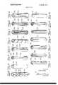
- FIG. 8is a perspective view of an alternate form of friction element which I may employ in my frictional antirotation device.
- FIG. 9is a perspective view of a further form of friction element which I may employ in my frictional antirotation device.
- FIG. 10is a perspective view of another form of friction element which I may employ in my frictional antirotation device.
- FIG. 11is a perspective view of yet another form of friction element which I may employ in my frictional antirotation device. 7
- FIG. 12is a perspective view of a still further form of friction element which I may employ in my frictional antirotation device.
- FIG. 13is a perspective view of another form of friction element which I may employ inmy frictional antirotation device.
- FIG. 14is a perspective view of a further form of friction element which I may employ in my frictional antirotation device. 1
- FIG. 15is a perspective view of a still further form of friction element which I may employ in my frictional antirotation device.
- FIG. 16is a perspective view of yet another form of friction element which I may employ in my frictional antirotation device.
- FIG. 17is a perspective view of a still further form of friction element which I may employ in my frictional antirotation device. 7
- FIG. 18is a perspective view of yet another alternate form of locking element which I may employ in my frictional antirotation device.
- FIG. l9is a perspective view of a further alternate form of spring pin which I may employ in my frictional antirotation device.
- FIG. 20is a perspective view of a still further alternate form of spring locking pin which I may employ in my frictional antirotation device.
- FIG. 21is a perspective view of another alternate form of locking element which I may employ in my frictional antirotation device.
- FIG. 22is a perspective view of a still further form of locking element which I may employ in my frictional antirotation device.
- FIGS. 1 and 2I have shown one embodiment of a fastener assembly, indicated generally by the reference character 10, for securing a panel or the like 12 to a frame 14 which may be provided with an opening adapted to be covered by the panel 12.
- Iprovide a self-locking nut 16 having a central bore 18 28 and 30.
- I 4insert the end 30 of the pin-in the opening 22 and retain the pin in position in the nut by means of a small spring pin 32 which extends through aligned bores 34 in the base of the nut and through aligned openings 37 in the wall of the pin. In this manner I secure the friction pin 24 in assembled relationship with the nut 16.
- FIGS. 1 and 2The other element of the form of fastener illustrated, in FIGS. 1 and 2 is a bolt 36 having a shank provided with threads 38 and with a generally hexagonal head 40.
- the pin 24is in frictional engagement with the wall of the bore 42.
- Iso construct the pin and the bore that I provide a relatively high frictional antirotation force as soon as the nut and bolt have been relatively rotated through only a couple of turns from the point of initial engagement of the threads.
- the fasteneris frictionally locked up" after only a short distance from the point of initial engagement of the threads of the nut and the bolt.
- This frictional forceis sufficient to cause the fastener to withstand extremes of vibration without disengagement.
- the forcemoreover is independent of the stress in the threads since it is provided by the spring pin 24 and the inner surface of the bore 42.
- the form of my spring pin 24 shown in FIGS. 1 and 2may be formed of any suitable material such, for example, as spring steel.
- FIG. 3I have shown an alternate form of fastener, indicated generally by the reference character 50, in which the friction locking pin is carried by the bolt of the assembly.
- This form of fastenerincludes a bolt 52 having threads 54 along its shank and having a head 56 which may, for example, be generally hexagonal.
- a smaller spring pin 62extending through bores 64 in the shank of the bolt 52 and through aligned openings in the wall of the friction locking pin 60 retain the pin in position in the bore 58.
- the fastenerincludes a friction locking nut subassembly, indicated generally by the reference character 86, adapted to be assembled in operative relationship with an opening 88 in the frame 84.
- the subassembly 86includes an adapter 90 having a central boss 92 adapted to fit in the opening 88 and having a hole 94 for receiving the bolt in a mannerto be described.
- any suitable meanssuch, for example, as rivets 96 may be employed to hold a nut-retaining cage 98'and the adapter 90 in assembled relationship on the frame 84.
- the nut 100 of the subassembly 86has a tapered end 102 adapted to cooperate with a counterbore 104 around the hole 94 when the fastener is drawn tight.
- Iprovide nut 100 with an axially extending bore 106 having threads 108 along a portion of the length thereof.
- the lower portion 110 of bore 106receives a plug 112 having an opening 114 for the friction locking pin 116 of this assembly.
- a smaller locking spring pin 118extends through the wall of the nut, through the plug 112 and through the wall of the pin 116 to secure the pin in operative relationship with the nut.
- the stud subassembly, indicated generally by the reference character 120, of this form of my fastenerincludes a grommet 122 secured in operative relationship with a counterbored opening 124 in the panel 82 by any suitable means known to the art.
- Grommet 122is provided with an annular recess for receiving a retainer ring 126.
- the bolt 128 of this form of my fastenerhas external threads 130 adapted to cooperate with the internal threads 108 of the nut 100.
- the head 132 of the boltis provided with a suitable slot 134 for the reception of a tool, such as a screwdriver or the like.
- the bolt 128has an axially extending bore 138 provided with an enlarged mouth 140. As the fastener elements are drawn together the friction pin 116 enters the bore 138 through the mouth 140. I so construct the parts that the pin 116 and the wall of the bore 138 cooperate to provide a'relatively high frictional antirotation or locking-up" force after only a relatively small movement of the bolt 128 and nut 100 together from the point of initial engagement of the threads 108. and 130.
- FIGS. 5 to 7 of the drawingsI have shown a further form of my fastener employing my frictional antirotation device.
- the form of my fastener shown in these Figuresincludes a screw assembly, indicated generally by the reference character 142, a screw assembly retaining ring 144, and a receptacle assembly, indicated generally by the reference character 146.
- the screw assembly 142includes an outer bushing 148 having a head 150 adapted to be received in the counterbore 152 of an opening 154 in one of the members such as a panel 156 adapted to be assembled onto a frame 158 or the like. 1 form the wall of the bushing 148 below the head 150 with a plurality of spaced, vertically extending slots 160.
- the retaining ring 144which normally rests in an annular groove 162 in the underside of the panel 156 is provided with a plurality of radially inwardly extending resilient tongues 164 spaced around the inner periphery of the ring correspondingly to the slots 160.
- the retaining ring 144is placed in the recess 162 and the screw assembly 142 is pushed in through the opening 154 until the tongues 164 ride into the slots so as to retain the screw assembly 142 on the panel 156.
- the assembly 142includes a screw 172 having external threads 174 along the length thereof and having a head 176 provided with an opening 178 of any suitable type for receiving a tool (not shown) to permit the screw to be driven.
- Screw 172is received in the bore 180 of the bushing.
- Iprovide the bushing with an annular internal lip or tongue 182 extending inwardly from the wall of the bore 180 into a circumferential groove 184 on the outer surface of the screw 172. Lip 182 and groove 184 cooperate to ensure that the bushing 148 moves with the screw 172 as the latter is screwed in and retracted.
- the form of the receptacle assembly 146 shown in FIGS. 5 to 7includes a nut having a head 190 and a shank 192 having internal threads 194 adapted to cooperate with the external threads 174 of the screw 172.
- Plug 198receives a locking pin 204 for securing pin 202 to the plug.
- Imay retain the plug 198 in the recess 196 by any suitable means such, for example, as by upsetting an edge 206 of the recess.
- the shank 192which may for example be square, extends through a square opening 208 in a nut stop 210 having laterally extending base portions 212.
- the nut 190while having limited movement in all directions is restrained against rotation relative to frame 158 and is retained thereon by a combined cage and dust cover 214 having laterally extending base portions 216. Any suitable means, such as rivets 218 or the like, may be employed to hold the cover 214 and the stop 210 in assembled relationship with the frame 158 over the frame opening 220.
- FIG. 8illustrates a generally tubular spring pin or friction locking element 222 which may have a spiral wall slit 224 forming feathered edges on the tube 222 at the slit. This is distinguished from the form of locking pin illustrated in FIGS. 1 and 2 having a straight slot 58 which might of course be tapered.
- FIG. 9shows a compound friction locking element in which an inner tubular member 226 having a longitudinal slot 228 extending throughout its length is nested within an outer tubular member 230 having a slot 232 extending throughout the length of its wall.
- an inner tubular member 226 having a longitudinal slot 228 extending throughout its lengthis nested within an outer tubular member 230 having a slot 232 extending throughout the length of its wall.
- the member 234 shown in FIG. 10is tubular and has a wall slot 236. This member, however, is provided with a core 238 of a suitable resilient material such as a plastic or the like.
- FIG. 11illustrates yet another member 240 which is formed with a helical wall slot 242.
- the direction in which the slot 242 extends with relation to the direction of the screw threads of the fasteneris such that the fastener is relatively easy to turn down but is relatively difiicult to retract.
- FIGS. 12 and 13respectively show a tubular element 224 having a slot 246 and provided with a knurled outer surface 248 and an element 250 having a slot 252 and provided with a serrated outer surface 254.
- the form of element 256 shown in FIG. 14is generally tubular and has a slot 258. I provide this member 256 with an enlarged base 260 which replaces the plug, such as the plug 112 in FIG. 3 or the plug 198 in FIG. 7, to facilitate assembly of the friction element.
- the slot 258may extend throughout the entire length of the element 256 or it may terminate at a location above the base. Moreover, more than a single slot might be provided. I may form the element 256 from sheet material or, alternatively, it might be machined.
- the slot 258may be straight or, if desirable, in some applications it may be tapered.
- FIG. 15I have shown a generally tubular friction locking element 262 having a longitudinally extending slot 264 in its wall and so shaped as to have a varying diameter along the length thereof.
- FIG. 16shows a noncircular cross-sectional shape friction element 266 having a wall slot 268.
- the element 270 shown in FIG. 17is generally U-shaped and may readily be formed from sheet metal.
- FIG. 18illustrates a friction locking element 272 having a spiral or coillike cross-sectional shape.
- the direction of the coil from inside to outsideis so selected as to be the same as the direction of rotation of the fastener element which rotates relative thereto during a fastening operation.
- the partscan be made relatively easy to fasten and relatively more difficult to unfasten.
- FIG. 19shows a form of my friction locking element 274 which is coiled from a length of wire and which is formed with a tapered free end. As in the form of my locking element shown in FIG. 18, the element 274 affords an easy in-hard out" action.
- FIG. 20illustrates another modification of my friction locking element 276 which is S-shaped in cross section. Fillers 278 of a resilient material may be provided. This element also is so oriented as to give easy in-hard out action.
- FIG. 21I have shown a solid friction locking pin 280 having a tapered end 282.
- This pinis formed of a material having inherent elasticity. For example, it may be made from fibrous material or from nylon or the like.
- FIG. 22shows an element 284 which is tubular and which has a longitudinal wall slot 286. I provide this element with transverse wall slots 288.
- the various form of friction locking elementwhich I have described are by way of example, it being understood that I may employ any variation or modification which will provide the desired high frictional force when the fastener is locked up.
- Various materialsincluding those mentioned hereinabove, may be used to form the spring locking pin. Spring steel and similar materials are appropriate for some forms of my pin. Other materials, such as nylon and fibrous materials, may be suitable for other forms of the locking element.
- the locking force providedmay be predetermined by selection of the material employed for the pin as well as its construction and its diameter relative to the diameter of the pin-receiving bore. The easy in-hard out feature may be provided if desired.
- FIG. 3The operation of the form of my fastener shown in FIG. 3 is analogous to that of the fastener shown in FIGS. 1 and 2.
- the two forms of fastenerdiffer structurally in that the friction locking pin 60 of the form of my fastener shown in FIG. 3 is carried by the bolt rather than by a nut.
- pin 60begins to engage the wall of bore 72 so that a high frictional antirotation force is provided after only a small relative movement of the fastener elements.
- the fastener shown in FIG. 4operates in a manner similar to that described in connection with FIGS. 1 and 2.
- This form of my fastenerdiffers in that the nut 100 is held captive by the cage 98 and 1 provide means for preventing the screw 128 from falling away from panel 82.
- the retaining ring 64holds the screw assembly 142 on the panel 156 for movement between its retracted and its screwed-in positions.
- the detents 168releasably hold the screw assembly in its retracted position for operation when desired. 1
- FIGS. 8 through 21may be adapted to the various forms of fasteners illustrated in FlGS. 1 to 7.
- lhave accomplished the object of my invention.
- lhave provided a frictional antirotation device for use in a fastener to overcome the defects of fasteners of the prior art.
- My devicefrictionally locks up a threaded fastener without excessively stressing the threads of the fastener.
- a fastener incorporating my devicehas an extremely long life. It can be unfastened and refastened thousands of times without wearing out. it is extremely simple in its construction and in its operation.
- An assembly for mounting a fastener in a hole on a panelincluding in combination, a bushing disposed in said hole, a fastener disposed in said bushing, means operatively connecting said bushing and said fastener for concomitant axial movement and for relative rotary movement, means for limiting movement of said bushing relative to said panel to movement between a retracted position and an extended position, a ring of resilient material housed by said bushing, and detents formed in said ring, openings in the wall of said bushing through which said detents extend, said detents extending beyond the edge of said hole in the extended position of the bushing releasably to hold the bushing in its extended position.
- said limiting meanscomprises a retaining ring surrounding said bushing, said bushing provided with longitudinally extending slots and projections on said retaining ring extending into said slots.
- a fastener assemblyincluding in combination a first elongated member having external threads along the length thereof, a second member provided with a generally cylindrical recess having a wall and having internal threads in said wall, said members being threadably interengageable over a length of travel from a point of initial engagement of said threads in response to relative rotation of said members around an axis; a generally cylindrical spring pin having a diameter less than that of said recess, and less than the minor diameter of said internal threads, means securing said pin to one of said members for movement therewith, and a generally cylindrical bore in the other member for receiving said pin, said bore having a diameter less than that of said recess and less than the minor diameter of said internal threads, said pin and said bore extending in the direction of said axis and being coaxial therewith, said bore having a diameter less than that of said pin to cause said pin frictionally to engage the wall of said bore in response to threaded interengagement of said members, one of said pin and said bore having a tapered portion facilitating entry of
- a fastener assemblyincluding in combination a first elongated member having external threads along the length thereof, a second member provided with a recess having a wall and having internal threads in said wall, said members being threadably interengageable over a length of travel from a point of initial engagement of said threads in response to relative rotation of said members around an axis, a first generally cylindrical bore In said first member, a second genera ly cylmdrical bore in the base of said recess in said second member, said second bore being of smaller diameter than said recess, said bores extending in the direction of said axis and being coaxial therewith, a generally cylindrical spring pin elongated in the direction of said axis and means for securing said spring pin in one of said bores with a length thereof extending out of the bore, said other bore having a diameter less than said spring pin to cause said pin frictionally to engage the wall of the other bore in response to threaded interengagement of said members.
- a fastener assembly as in claim 4in which said pin is tubular and in which said pin has a helical slot extending throughout the length of the wall thereof, the direction of said helical slot being opposite .to the direction of said threads.
- a fastener as in claim 4in which said pin is provided with a plurality of slits extending partially along its length to form a cantilever spring.
- An assembly as in claim 4including an enlarged base on said pin to facilitate mounting of said pin in said one bore.
- An assembly as in claim 20including fillers of resilient material in the curves of said S-shaped pins.
- An assembly as in claim 4including means for mounting said first member in a hole on a panel, said mounting means comprising a bushing disposed in said hole, said first member being disposed in said bushing, means operatively connecting said bushing and said first member for concomitant axial movement and for relative rotary movement, means for limiting movement of said bushing relative to said panel to movement between a retracted position and an extended position, a ring of resilient material housed by said bushing and detents formed in said ring, openings in the wall of said bushing through which said detents extend, said detents extending beyond the edge of said hole in the extended position of the bushing releasably to hold the bushing in its extended position.
Landscapes
- Engineering & Computer Science (AREA)
- General Engineering & Computer Science (AREA)
- Mechanical Engineering (AREA)
- Dowels (AREA)
Abstract
Description
Claims (22)
Applications Claiming Priority (2)
| Application Number | Priority Date | Filing Date | Title |
|---|---|---|---|
| US70856568A | 1968-02-27 | 1968-02-27 | |
| US88050469A | 1969-12-11 | 1969-12-11 |
Publications (1)
| Publication Number | Publication Date |
|---|---|
| US3630261Atrue US3630261A (en) | 1971-12-28 |
Family
ID=27108117
Family Applications (1)
| Application Number | Title | Priority Date | Filing Date |
|---|---|---|---|
| US880504AExpired - LifetimeUS3630261A (en) | 1968-02-27 | 1969-12-11 | Frictional antirotation device |
Country Status (1)
| Country | Link |
|---|---|
| US (1) | US3630261A (en) |
Cited By (51)
| Publication number | Priority date | Publication date | Assignee | Title |
|---|---|---|---|---|
| US3922867A (en)* | 1974-01-04 | 1975-12-02 | James J Scott | Friction rock stabilizers |
| US3967399A (en)* | 1974-08-05 | 1976-07-06 | Caterpillar Tractor Co. | Retaining means for ground-engaging tool |
| US4012913A (en)* | 1975-10-03 | 1977-03-22 | Scott James J | Friction rock stabilizers |
| USRE30256E (en)* | 1973-02-09 | 1980-04-08 | Deborah L. Castle | Friction rock stabilizers |
| US4252167A (en)* | 1977-12-07 | 1981-02-24 | Shur-Lok International S.A. | Device for positively locking a screw in a tapped hole |
| WO1981002605A1 (en)* | 1980-03-07 | 1981-09-17 | A Ciavatta | Oblate friction rock stabilizer and installation lubricating cement utilized therewith |
| US4316677A (en)* | 1980-03-07 | 1982-02-23 | Armand Ciavatta | Tubular shank device |
| FR2529489A1 (en)* | 1982-06-30 | 1984-01-06 | Luk Lamellen & Kupplungsbau | FRICTION CLUTCH MOUNTED BY RIVETTING BLADE SPRINGS WITH THE PRESSURE PLATE, AND CORRESPONDING RIVER METHOD |
| FR2529488A1 (en)* | 1982-06-30 | 1984-01-06 | Luk Lamellen & Kupplungsbau | FRICTION CLUTCH MOUNTED BY RIVETTING BLADE SPRINGS WITH THE PRESSURE PLATE, AND CORRESPONDING RIVER METHOD |
| US4430025A (en) | 1981-03-04 | 1984-02-07 | Armand Ciavatta | Oblate friction rock stabilizer and installation lubricating cement utilized therewith |
| US4875819A (en)* | 1988-10-11 | 1989-10-24 | Kevin Wilkinson | Wheel lock system apparatus |
| US20040059334A1 (en)* | 1999-09-13 | 2004-03-25 | Synthes (U.S.A.) | Bone plating system |
| US6735905B1 (en)* | 2001-03-14 | 2004-05-18 | Chi Overhead Doors, Inc. | Ratcheting winding cone |
| US20040167522A1 (en)* | 2001-05-28 | 2004-08-26 | Alfred Niederberger | Bone plate |
| US20070155271A1 (en)* | 2005-12-30 | 2007-07-05 | Touzov Igor V | Heat conductive textile and method producing thereof |
| US20080033430A1 (en)* | 2003-09-08 | 2008-02-07 | Joseph Ferrante | Orthopaedic Plate and Screw Assembly |
| US20080083707A1 (en)* | 2006-10-05 | 2008-04-10 | Newfrey Llc | Stud holder |
| US7780667B2 (en) | 2003-09-08 | 2010-08-24 | Smith & Nephew, Inc. | Orthopaedic plate and screw assembly |
| US7799030B2 (en) | 2003-09-08 | 2010-09-21 | Smith & Nephew, Inc. | Orthopaedic plate and screw assembly |
| US7918853B2 (en) | 2007-03-20 | 2011-04-05 | Smith & Nephew, Inc. | Orthopaedic plate and screw assembly |
| US20110091298A1 (en)* | 2009-10-19 | 2011-04-21 | Bowers Ned C | Fastener for securing together two panels |
| US8105367B2 (en) | 2003-09-29 | 2012-01-31 | Smith & Nephew, Inc. | Bone plate and bone plate assemblies including polyaxial fasteners |
| WO2012038216A1 (en)* | 2010-09-24 | 2012-03-29 | Robert Bosch Gmbh | Dowel pin |
| US8147493B2 (en) | 2003-09-08 | 2012-04-03 | Synthes Usa, Llc | Bone-fixation device |
| US8246661B2 (en) | 2003-10-30 | 2012-08-21 | Synthes Usa, Llc | Bone plate |
| US8343196B2 (en) | 2003-08-26 | 2013-01-01 | Synthes Usa, Llc | Bone plate |
| US8382807B2 (en) | 2005-07-25 | 2013-02-26 | Smith & Nephew, Inc. | Systems and methods for using polyaxial plates |
| US8449544B2 (en) | 2009-06-30 | 2013-05-28 | Smith & Nephew, Inc. | Orthopaedic implant and fastener assembly |
| US8574268B2 (en) | 2004-01-26 | 2013-11-05 | DePuy Synthes Product, LLC | Highly-versatile variable-angle bone plate system |
| US8758346B2 (en) | 2009-09-14 | 2014-06-24 | DePuy Synthes Products, LLC | Variable angle compression plate |
| US8757952B2 (en) | 2009-10-19 | 2014-06-24 | Bowers Ned C | Fastener for securing together two panels |
| US20140180313A1 (en)* | 2011-08-18 | 2014-06-26 | Anchor Orthopedics Xt Inc. | Suture Passing Instrumentation and Methods of use Thereof |
| CN104033468A (en)* | 2014-06-19 | 2014-09-10 | 宁波浩渤工贸有限公司 | Anti-dropping bolt |
| US8834469B2 (en) | 2009-06-30 | 2014-09-16 | Smith & Nephew, Inc. | Orthopaedic implant and fastener assembly |
| US8940028B2 (en) | 2005-07-25 | 2015-01-27 | Smith & Nephew, Inc. | Systems and methods for using polyaxial plates |
| US9168075B2 (en) | 2004-01-26 | 2015-10-27 | DePuy Synthes Products, Inc. | Variable angle locked bone fixation system |
| CN109070169A (en)* | 2016-04-19 | 2018-12-21 | 株式会社天田控股集团 | Metal die holder device and tubular part |
| US10231768B2 (en) | 2003-05-30 | 2019-03-19 | DePuy Synthes Products, Inc. | Methods for implanting bone plates |
| US10390866B2 (en) | 2011-06-15 | 2019-08-27 | Smith & Nephew, Inc. | Variable angle locking implant |
| US10539172B2 (en) | 2016-08-16 | 2020-01-21 | Ned C. Bowers | Fastener with a stud hold-out position |
| US10624686B2 (en) | 2016-09-08 | 2020-04-21 | DePuy Synthes Products, Inc. | Variable angel bone plate |
| US10772665B2 (en) | 2018-03-29 | 2020-09-15 | DePuy Synthes Products, Inc. | Locking structures for affixing bone anchors to a bone plate, and related systems and methods |
| US10820930B2 (en) | 2016-09-08 | 2020-11-03 | DePuy Synthes Products, Inc. | Variable angle bone plate |
| US10905476B2 (en) | 2016-09-08 | 2021-02-02 | DePuy Synthes Products, Inc. | Variable angle bone plate |
| US10925651B2 (en) | 2018-12-21 | 2021-02-23 | DePuy Synthes Products, Inc. | Implant having locking holes with collection cavity for shavings |
| US10993750B2 (en) | 2015-09-18 | 2021-05-04 | Smith & Nephew, Inc. | Bone plate |
| US11013541B2 (en) | 2018-04-30 | 2021-05-25 | DePuy Synthes Products, Inc. | Threaded locking structures for affixing bone anchors to a bone plate, and related systems and methods |
| US11026727B2 (en) | 2018-03-20 | 2021-06-08 | DePuy Synthes Products, Inc. | Bone plate with form-fitting variable-angle locking hole |
| US11259851B2 (en) | 2003-08-26 | 2022-03-01 | DePuy Synthes Products, Inc. | Bone plate |
| US11291484B2 (en) | 2004-01-26 | 2022-04-05 | DePuy Synthes Products, Inc. | Highly-versatile variable-angle bone plate system |
| US12009624B2 (en) | 2019-02-06 | 2024-06-11 | Sumitomo Wiring Systems, Ltd. | Terminal holding structure and wiring module |
Citations (8)
| Publication number | Priority date | Publication date | Assignee | Title |
|---|---|---|---|---|
| US623124A (en)* | 1899-04-18 | Adjustable axle-nut | ||
| US623126A (en)* | 1899-04-18 | Adjustable axle-nut | ||
| US733532A (en)* | 1903-01-08 | 1903-07-14 | Samuel R Bailey | Axle-nut. |
| US2758625A (en)* | 1952-12-05 | 1956-08-14 | Illinois Tool Works | Fastener comprising a threaded receptacle, co-operating threaded stud and spring detent locking means thereon |
| US2853112A (en)* | 1954-04-27 | 1958-09-23 | Illinois Tool Works | Locked bolt and shear resisting grommet means |
| US2922211A (en)* | 1955-10-04 | 1960-01-26 | Illinois Tool Works | Quick fastener unit |
| US2972367A (en)* | 1957-07-18 | 1961-02-21 | United Carr Fastener Corp | Fastening device |
| US3037542A (en)* | 1959-02-05 | 1962-06-05 | Illinois Tool Works | Stud assembly having grommet with grommet jacking spring |
- 1969
- 1969-12-11USUS880504Apatent/US3630261A/ennot_activeExpired - Lifetime
Patent Citations (8)
| Publication number | Priority date | Publication date | Assignee | Title |
|---|---|---|---|---|
| US623124A (en)* | 1899-04-18 | Adjustable axle-nut | ||
| US623126A (en)* | 1899-04-18 | Adjustable axle-nut | ||
| US733532A (en)* | 1903-01-08 | 1903-07-14 | Samuel R Bailey | Axle-nut. |
| US2758625A (en)* | 1952-12-05 | 1956-08-14 | Illinois Tool Works | Fastener comprising a threaded receptacle, co-operating threaded stud and spring detent locking means thereon |
| US2853112A (en)* | 1954-04-27 | 1958-09-23 | Illinois Tool Works | Locked bolt and shear resisting grommet means |
| US2922211A (en)* | 1955-10-04 | 1960-01-26 | Illinois Tool Works | Quick fastener unit |
| US2972367A (en)* | 1957-07-18 | 1961-02-21 | United Carr Fastener Corp | Fastening device |
| US3037542A (en)* | 1959-02-05 | 1962-06-05 | Illinois Tool Works | Stud assembly having grommet with grommet jacking spring |
Cited By (103)
| Publication number | Priority date | Publication date | Assignee | Title |
|---|---|---|---|---|
| USRE30256E (en)* | 1973-02-09 | 1980-04-08 | Deborah L. Castle | Friction rock stabilizers |
| US3922867A (en)* | 1974-01-04 | 1975-12-02 | James J Scott | Friction rock stabilizers |
| US3967399A (en)* | 1974-08-05 | 1976-07-06 | Caterpillar Tractor Co. | Retaining means for ground-engaging tool |
| US4012913A (en)* | 1975-10-03 | 1977-03-22 | Scott James J | Friction rock stabilizers |
| US4252167A (en)* | 1977-12-07 | 1981-02-24 | Shur-Lok International S.A. | Device for positively locking a screw in a tapped hole |
| WO1981002605A1 (en)* | 1980-03-07 | 1981-09-17 | A Ciavatta | Oblate friction rock stabilizer and installation lubricating cement utilized therewith |
| JPS57500254A (en)* | 1980-03-07 | 1982-02-12 | ||
| US4316677A (en)* | 1980-03-07 | 1982-02-23 | Armand Ciavatta | Tubular shank device |
| US4430025A (en) | 1981-03-04 | 1984-02-07 | Armand Ciavatta | Oblate friction rock stabilizer and installation lubricating cement utilized therewith |
| FR2529489A1 (en)* | 1982-06-30 | 1984-01-06 | Luk Lamellen & Kupplungsbau | FRICTION CLUTCH MOUNTED BY RIVETTING BLADE SPRINGS WITH THE PRESSURE PLATE, AND CORRESPONDING RIVER METHOD |
| FR2529488A1 (en)* | 1982-06-30 | 1984-01-06 | Luk Lamellen & Kupplungsbau | FRICTION CLUTCH MOUNTED BY RIVETTING BLADE SPRINGS WITH THE PRESSURE PLATE, AND CORRESPONDING RIVER METHOD |
| US4875819A (en)* | 1988-10-11 | 1989-10-24 | Kevin Wilkinson | Wheel lock system apparatus |
| US20080132960A1 (en)* | 1999-09-13 | 2008-06-05 | Weaver Paul C | Bone Plating System |
| US20040059335A1 (en)* | 1999-09-13 | 2004-03-25 | Synthes (U.S.A.) | Bone plating system |
| US9211151B2 (en) | 1999-09-13 | 2015-12-15 | DePuy Synthes Products, Inc. | Bone plating system |
| US20050080421A1 (en)* | 1999-09-13 | 2005-04-14 | Synthes (Usa) | Bone plating system |
| US7128744B2 (en)* | 1999-09-13 | 2006-10-31 | Synthes (Usa) | Bone plating system |
| US20040059334A1 (en)* | 1999-09-13 | 2004-03-25 | Synthes (U.S.A.) | Bone plating system |
| US8641744B2 (en) | 1999-09-13 | 2014-02-04 | DePuy Synthes Products, LLC | Bone plating system |
| US7341589B2 (en)* | 1999-09-13 | 2008-03-11 | Synthes (U.S.A.) | Bone plating system |
| US6735905B1 (en)* | 2001-03-14 | 2004-05-18 | Chi Overhead Doors, Inc. | Ratcheting winding cone |
| US7655029B2 (en) | 2001-05-28 | 2010-02-02 | Synthes Usa, Llc | Bone plate |
| US20040167522A1 (en)* | 2001-05-28 | 2004-08-26 | Alfred Niederberger | Bone plate |
| US10653466B2 (en) | 2003-05-30 | 2020-05-19 | DePuy Synthes Products, Inc. | Bone plate |
| US10231768B2 (en) | 2003-05-30 | 2019-03-19 | DePuy Synthes Products, Inc. | Methods for implanting bone plates |
| US11419647B2 (en) | 2003-05-30 | 2022-08-23 | DePuy Synthes Products, Inc. | Bone plate |
| US8845698B2 (en) | 2003-08-26 | 2014-09-30 | DePuy Synthes Products, LLC | Bone plate |
| US8852245B2 (en) | 2003-08-26 | 2014-10-07 | DePuy Synthes Products, LLC | Bone plate |
| US8343196B2 (en) | 2003-08-26 | 2013-01-01 | Synthes Usa, Llc | Bone plate |
| US8876873B2 (en) | 2003-08-26 | 2014-11-04 | DePuy Synthes Products, LLC | Bone plate |
| US11259851B2 (en) | 2003-08-26 | 2022-03-01 | DePuy Synthes Products, Inc. | Bone plate |
| US10342586B2 (en) | 2003-08-26 | 2019-07-09 | DePuy Synthes Products, Inc. | Bone plate |
| US9295505B2 (en) | 2003-08-26 | 2016-03-29 | DePuy Synthes Products, Inc. | Bone plate |
| US7931652B2 (en) | 2003-09-08 | 2011-04-26 | Smith & Nephew, Inc. | Orthopaedic plate and screw assembly |
| US8105326B2 (en) | 2003-09-08 | 2012-01-31 | Smith & Nephew, Inc. | Orthopaedic implant and fastener assembly |
| US8147493B2 (en) | 2003-09-08 | 2012-04-03 | Synthes Usa, Llc | Bone-fixation device |
| US8187275B2 (en) | 2003-09-08 | 2012-05-29 | Smith & Nephew, Inc. | Orthopaedic implant and fastening assembly |
| US7883509B2 (en) | 2003-09-08 | 2011-02-08 | Smith & Nephew, Inc. | Orthopaedic implant and screw assembly |
| US8298234B2 (en) | 2003-09-08 | 2012-10-30 | Smith & Nephew, Inc. | Orthopaedic implant and fastener assembly |
| US7799030B2 (en) | 2003-09-08 | 2010-09-21 | Smith & Nephew, Inc. | Orthopaedic plate and screw assembly |
| US7780667B2 (en) | 2003-09-08 | 2010-08-24 | Smith & Nephew, Inc. | Orthopaedic plate and screw assembly |
| US8617161B2 (en) | 2003-09-08 | 2013-12-31 | Smith & Nephew, Inc. | Orthopaedic plate and fastener assembly |
| US20080033430A1 (en)* | 2003-09-08 | 2008-02-07 | Joseph Ferrante | Orthopaedic Plate and Screw Assembly |
| US8992581B2 (en) | 2003-09-29 | 2015-03-31 | Smith & Nephew, Inc. | Bone plate and bone plate assemblies including polyaxial fasteners |
| US8105367B2 (en) | 2003-09-29 | 2012-01-31 | Smith & Nephew, Inc. | Bone plate and bone plate assemblies including polyaxial fasteners |
| US8246661B2 (en) | 2003-10-30 | 2012-08-21 | Synthes Usa, Llc | Bone plate |
| US9168075B2 (en) | 2004-01-26 | 2015-10-27 | DePuy Synthes Products, Inc. | Variable angle locked bone fixation system |
| US8574268B2 (en) | 2004-01-26 | 2013-11-05 | DePuy Synthes Product, LLC | Highly-versatile variable-angle bone plate system |
| US10335211B2 (en) | 2004-01-26 | 2019-07-02 | DePuy Synthes Products, Inc. | Highly-versatile variable-angle bone plate system |
| US11291484B2 (en) | 2004-01-26 | 2022-04-05 | DePuy Synthes Products, Inc. | Highly-versatile variable-angle bone plate system |
| US9314284B2 (en) | 2004-01-26 | 2016-04-19 | DePuy Synthes Products, Inc. | Highly-versatile variable-angle bone plate system |
| US10092337B2 (en) | 2005-07-25 | 2018-10-09 | Smith & Nephew, Inc. | Systems and methods for using polyaxial plates |
| US12343053B2 (en) | 2005-07-25 | 2025-07-01 | Smith & Nephew, Inc. | Systems and methods for using polyaxial plates |
| US10736680B2 (en) | 2005-07-25 | 2020-08-11 | Smith & Nephew, Inc. | Systems and methods for using polyaxial plates |
| US8382807B2 (en) | 2005-07-25 | 2013-02-26 | Smith & Nephew, Inc. | Systems and methods for using polyaxial plates |
| US10327822B2 (en) | 2005-07-25 | 2019-06-25 | Smith & Nephew, Inc. | Systems and methods for using polyaxial plates |
| US8888824B2 (en) | 2005-07-25 | 2014-11-18 | Smith & Nephew, Inc. | Systems and methods for using polyaxial plates |
| US10292741B2 (en) | 2005-07-25 | 2019-05-21 | Smith & Nephew, Inc. | Systems and methods for using polyaxial plates |
| US8940028B2 (en) | 2005-07-25 | 2015-01-27 | Smith & Nephew, Inc. | Systems and methods for using polyaxial plates |
| US10080598B2 (en) | 2005-07-25 | 2018-09-25 | Smith & Nephew, Inc. | Systems and methods for using polyaxial plates |
| US11896270B2 (en) | 2005-07-25 | 2024-02-13 | Smith & Nephew, Inc. | Systems and methods for using polyaxial plates |
| US9795424B2 (en) | 2005-07-25 | 2017-10-24 | Smith & Nephew, Inc. | Systems and methods for using polyaxial plates |
| US20070155271A1 (en)* | 2005-12-30 | 2007-07-05 | Touzov Igor V | Heat conductive textile and method producing thereof |
| US20080083707A1 (en)* | 2006-10-05 | 2008-04-10 | Newfrey Llc | Stud holder |
| US7918853B2 (en) | 2007-03-20 | 2011-04-05 | Smith & Nephew, Inc. | Orthopaedic plate and screw assembly |
| US20110238121A1 (en)* | 2007-03-20 | 2011-09-29 | Smith & Nephew, Inc. | Orthopaedic plate and screw assembly |
| US8939978B2 (en) | 2007-03-20 | 2015-01-27 | Smith & Nephew, Inc. | Orthopaedic plate and screw assembly |
| US8834469B2 (en) | 2009-06-30 | 2014-09-16 | Smith & Nephew, Inc. | Orthopaedic implant and fastener assembly |
| US8449544B2 (en) | 2009-06-30 | 2013-05-28 | Smith & Nephew, Inc. | Orthopaedic implant and fastener assembly |
| US8758346B2 (en) | 2009-09-14 | 2014-06-24 | DePuy Synthes Products, LLC | Variable angle compression plate |
| US20110268536A1 (en)* | 2009-10-19 | 2011-11-03 | Bowers Ned C | Fastener for securing together two panels |
| US20110091298A1 (en)* | 2009-10-19 | 2011-04-21 | Bowers Ned C | Fastener for securing together two panels |
| US8282329B2 (en)* | 2009-10-19 | 2012-10-09 | Ned C. Powers | Fastener for securing together two panels |
| US8757952B2 (en) | 2009-10-19 | 2014-06-24 | Bowers Ned C | Fastener for securing together two panels |
| US7997843B2 (en)* | 2009-10-19 | 2011-08-16 | Bowers Ned C | Fastener for securing together two panels |
| JP2013543089A (en)* | 2010-09-24 | 2013-11-28 | ローベルト ボツシユ ゲゼルシヤフト ミツト ベシユレンクテル ハフツング | spring pin |
| WO2012038216A1 (en)* | 2010-09-24 | 2012-03-29 | Robert Bosch Gmbh | Dowel pin |
| US10390866B2 (en) | 2011-06-15 | 2019-08-27 | Smith & Nephew, Inc. | Variable angle locking implant |
| US10448980B2 (en) | 2011-06-15 | 2019-10-22 | Smith & Nephew, Inc. | Variable angle locking implant |
| US12390253B2 (en) | 2011-06-15 | 2025-08-19 | Smith & Nephew, Inc. | Variable angle locking implant |
| US10405901B2 (en) | 2011-06-15 | 2019-09-10 | Smith & Nephew, Inc. | Variable angle locking implant |
| US11389156B2 (en)* | 2011-08-18 | 2022-07-19 | Anchor Orthopedics Xt Inc. | Suture passing instrumentation and methods of use thereof |
| US10383620B2 (en)* | 2011-08-18 | 2019-08-20 | Anchor Orthopedics Xt Inc. | Suture passing instrumentation and methods of use thereof |
| US20140180313A1 (en)* | 2011-08-18 | 2014-06-26 | Anchor Orthopedics Xt Inc. | Suture Passing Instrumentation and Methods of use Thereof |
| CN104033468B (en)* | 2014-06-19 | 2015-12-02 | 宁波浩渤工贸有限公司 | A kind of Anti-extrusion bolt |
| CN104033468A (en)* | 2014-06-19 | 2014-09-10 | 宁波浩渤工贸有限公司 | Anti-dropping bolt |
| US11534213B2 (en) | 2015-09-18 | 2022-12-27 | Smith & Nephew, Inc. | Bone plate |
| US10993750B2 (en) | 2015-09-18 | 2021-05-04 | Smith & Nephew, Inc. | Bone plate |
| US11974787B2 (en) | 2015-09-18 | 2024-05-07 | Smith & Nephew, Inc. | Bone plate |
| US11020783B2 (en) | 2016-04-19 | 2021-06-01 | Amada Holdings Co., Ltd. | Mold holder device and pipe member |
| CN109070169B (en)* | 2016-04-19 | 2021-08-10 | 株式会社天田控股集团 | Metal mold holder device and tubular member |
| EP3446801A4 (en)* | 2016-04-19 | 2019-04-24 | Amada Holdings Co., Ltd. | MOLD SUPPORTING DEVICE AND PIPE MEMBER |
| CN109070169A (en)* | 2016-04-19 | 2018-12-21 | 株式会社天田控股集团 | Metal die holder device and tubular part |
| US10539172B2 (en) | 2016-08-16 | 2020-01-21 | Ned C. Bowers | Fastener with a stud hold-out position |
| US11529176B2 (en) | 2016-09-08 | 2022-12-20 | DePuy Synthes Products, Inc. | Variable angle bone plate |
| US10905476B2 (en) | 2016-09-08 | 2021-02-02 | DePuy Synthes Products, Inc. | Variable angle bone plate |
| US10820930B2 (en) | 2016-09-08 | 2020-11-03 | DePuy Synthes Products, Inc. | Variable angle bone plate |
| US10624686B2 (en) | 2016-09-08 | 2020-04-21 | DePuy Synthes Products, Inc. | Variable angel bone plate |
| US11026727B2 (en) | 2018-03-20 | 2021-06-08 | DePuy Synthes Products, Inc. | Bone plate with form-fitting variable-angle locking hole |
| US10772665B2 (en) | 2018-03-29 | 2020-09-15 | DePuy Synthes Products, Inc. | Locking structures for affixing bone anchors to a bone plate, and related systems and methods |
| US11013541B2 (en) | 2018-04-30 | 2021-05-25 | DePuy Synthes Products, Inc. | Threaded locking structures for affixing bone anchors to a bone plate, and related systems and methods |
| US10925651B2 (en) | 2018-12-21 | 2021-02-23 | DePuy Synthes Products, Inc. | Implant having locking holes with collection cavity for shavings |
| US12009624B2 (en) | 2019-02-06 | 2024-06-11 | Sumitomo Wiring Systems, Ltd. | Terminal holding structure and wiring module |
Similar Documents
| Publication | Publication Date | Title |
|---|---|---|
| US3630261A (en) | Frictional antirotation device | |
| US3368602A (en) | Self-locking captive screw assembly | |
| US3156281A (en) | Fastener assembly with resilient locking retainer | |
| US2486670A (en) | Stud for cowl fasteners | |
| US2918841A (en) | Blind fastener formed of plastic and containing longitudinal slots which permit rosette type of distortion of shank | |
| US2730154A (en) | Self-locking fastener having longitudinal spring key detent means | |
| US7997843B2 (en) | Fastener for securing together two panels | |
| US5409338A (en) | Wedge-action lock washer assembly having coupled washers | |
| US4834601A (en) | Wall fastener | |
| US3650173A (en) | Positive locking snap-fastener | |
| US3241589A (en) | Positive self-locking fastening means | |
| US3180387A (en) | Floating fastener receptacle | |
| US5984602A (en) | Reversible threaded fastener system | |
| US3404716A (en) | Self-locking fastener | |
| US2667200A (en) | Fastening device | |
| US4789282A (en) | Expansion anchor stud | |
| JPS598687B2 (en) | tightening device | |
| EP0059316B1 (en) | Locking arrangement | |
| US3474846A (en) | Locking fastener | |
| US3877342A (en) | Cage nuts | |
| US2581288A (en) | Resilient screw fastener | |
| US4859127A (en) | Spring wire fastener and method of using same | |
| US3730243A (en) | Friction locks | |
| US2575311A (en) | Spring threaded bolt fastening device | |
| US3709086A (en) | High strength adjustable quarter turn fastener |
Legal Events
| Date | Code | Title | Description |
|---|---|---|---|
| AS | Assignment | Owner name:WADE, WILLIAM J., RODNEY SQUARE NORTH, WILMINGTON Free format text:SECURITY INTEREST;ASSIGNOR:REXNORD INC.;REEL/FRAME:004817/0047 Effective date:19870430 Owner name:WILMINGTON TRUST COMPANY, RODNEY SQUARE NORTH, WIL Free format text:SECURITY INTEREST;ASSIGNOR:REXNORD INC.;REEL/FRAME:004817/0047 Effective date:19870430 Owner name:REXNORD INC. Free format text:CHANGE OF NAME;ASSIGNOR:REX CHAIN BELT INC.;REEL/FRAME:004713/0513 Effective date:19850905 | |
| AS | Assignment | Owner name:REXNORD HOLDINGS INC., 350 N. SUNNY SLOPE, BROOKFI Free format text:ASSIGNMENT OF ASSIGNORS INTEREST.;ASSIGNOR:REXNORD INC., A CORP. OF WI;REEL/FRAME:004938/0476 Effective date:19880808 | |
| AS | Assignment | Owner name:WILMINGTON TRUST COMPANY AND WADE WILLIAM J. AS TR Free format text:ASSIGNMENT OF ASSIGNORS INTEREST;ASSIGNOR:REXNORD HOLDINGS INC., A CORP. OF DE;REEL/FRAME:004945/0853 Effective date:19880816 Owner name:WILMINGTON TRUST COMPANY AND WADE WILLIAM J. AS TR Free format text:ASSIGNMENT OF ASSIGNORS INTEREST. AMENDED SECURITY AGREEMENT;ASSIGNOR:REXNORD HOLDINGS INC., A CORP. OF DE;REEL/FRAME:004945/0853 Effective date:19880816 | |
| AS | Assignment | Owner name:CITICORP NORTH AMERICA, INC., ILLINOIS Free format text:ASSIGNMENT OF ASSIGNORS INTEREST;ASSIGNORS:WILMINGTON TRUST COMPANY;WADE, WILLIAM J.;REEL/FRAME:007677/0077 Effective date:19950222 |