US3618980A - Trap for nongaseous matter - Google Patents
Trap for nongaseous matterDownload PDFInfo
- Publication number
- US3618980A US3618980AUS870470AUS3618980DAUS3618980AUS 3618980 AUS3618980 AUS 3618980AUS 870470 AUS870470 AUS 870470AUS 3618980D AUS3618980D AUS 3618980DAUS 3618980 AUS3618980 AUS 3618980A
- Authority
- US
- United States
- Prior art keywords
- propellant
- chamber
- directing
- gas
- confining
- Prior art date
- Legal status (The legal status is an assumption and is not a legal conclusion. Google has not performed a legal analysis and makes no representation as to the accuracy of the status listed.)
- Expired - Lifetime
Links
- 239000003380propellantSubstances0.000claimsabstractdescription90
- 230000002401inhibitory effectEffects0.000claimsabstractdescription12
- 238000002485combustion reactionMethods0.000claimsdescription22
- 239000012768molten materialSubstances0.000abstractdescription2
- 239000011343solid materialSubstances0.000abstractdescription2
- 239000007789gasSubstances0.000description57
- 239000000463materialSubstances0.000description30
- 239000002245particleSubstances0.000description17
- 239000002826coolantSubstances0.000description6
- 239000011159matrix materialSubstances0.000description6
- 239000012528membraneSubstances0.000description5
- 239000007788liquidSubstances0.000description4
- 238000000034methodMethods0.000description3
- 230000008569processEffects0.000description3
- 230000008859changeEffects0.000description2
- 230000004044responseEffects0.000description2
- 230000009471actionEffects0.000description1
- 238000006243chemical reactionMethods0.000description1
- 238000010276constructionMethods0.000description1
- 238000001816coolingMethods0.000description1
- 230000000694effectsEffects0.000description1
- 230000002708enhancing effectEffects0.000description1
- 238000007689inspectionMethods0.000description1
- 239000000203mixtureSubstances0.000description1
- 230000004048modificationEffects0.000description1
- 238000012986modificationMethods0.000description1
- 239000000843powderSubstances0.000description1
- 230000000717retained effectEffects0.000description1
- 238000003466weldingMethods0.000description1
Images


Classifications
- B—PERFORMING OPERATIONS; TRANSPORTING
- B60—VEHICLES IN GENERAL
- B60R—VEHICLES, VEHICLE FITTINGS, OR VEHICLE PARTS, NOT OTHERWISE PROVIDED FOR
- B60R21/00—Arrangements or fittings on vehicles for protecting or preventing injuries to occupants or pedestrians in case of accidents or other traffic risks
- B60R21/02—Occupant safety arrangements or fittings, e.g. crash pads
- B60R21/16—Inflatable occupant restraints or confinements designed to inflate upon impact or impending impact, e.g. air bags
- B60R21/26—Inflatable occupant restraints or confinements designed to inflate upon impact or impending impact, e.g. air bags characterised by the inflation fluid source or means to control inflation fluid flow
- B60R21/264—Inflatable occupant restraints or confinements designed to inflate upon impact or impending impact, e.g. air bags characterised by the inflation fluid source or means to control inflation fluid flow using instantaneous generation of gas, e.g. pyrotechnic
- B60R21/2644—Inflatable occupant restraints or confinements designed to inflate upon impact or impending impact, e.g. air bags characterised by the inflation fluid source or means to control inflation fluid flow using instantaneous generation of gas, e.g. pyrotechnic using only solid reacting substances, e.g. pellets, powder
- B—PERFORMING OPERATIONS; TRANSPORTING
- B60—VEHICLES IN GENERAL
- B60R—VEHICLES, VEHICLE FITTINGS, OR VEHICLE PARTS, NOT OTHERWISE PROVIDED FOR
- B60R21/00—Arrangements or fittings on vehicles for protecting or preventing injuries to occupants or pedestrians in case of accidents or other traffic risks
- B60R21/02—Occupant safety arrangements or fittings, e.g. crash pads
- B60R21/16—Inflatable occupant restraints or confinements designed to inflate upon impact or impending impact, e.g. air bags
- B60R21/26—Inflatable occupant restraints or confinements designed to inflate upon impact or impending impact, e.g. air bags characterised by the inflation fluid source or means to control inflation fluid flow
- B60R21/261—Inflatable occupant restraints or confinements designed to inflate upon impact or impending impact, e.g. air bags characterised by the inflation fluid source or means to control inflation fluid flow with means other than bag structure to diffuse or guide inflation fluid
- F—MECHANICAL ENGINEERING; LIGHTING; HEATING; WEAPONS; BLASTING
- F42—AMMUNITION; BLASTING
- F42B—EXPLOSIVE CHARGES, e.g. FOR BLASTING, FIREWORKS, AMMUNITION
- F42B3/00—Blasting cartridges, i.e. case and explosive
- F42B3/04—Blasting cartridges, i.e. case and explosive for producing gas under pressure
Definitions
- This inventionrelates to a gas generator and inflatable bag device, particularly adapted for use in automatic vehicles, and more particularly to a device for preventing propellant emanating in a nongaseous state from the gas generator from reaching an inflatable bag or gas confining member.
- gas source or generator and inflatable bag devicesparticularly adapted for use in automotive vehicles are known.
- some of these devicesemploy a sealed cylinder of compressed gas connected directly or by a conduit to an inflatable bag mounted on the interior of the vehicle.
- a sensing deviceis conventionally provided for sensing rapid deceleration or change in velocity of the vehicle. Upon a predetermined change in vehicle velocity, such as upon impact with another object, the sensing device causes a signal to be sent to an actuating device for breaking the seal on the cylinder to release the gas to the bag. The latter inflates and provides a cushion against which an occupant may be thrown by the impact.
- Another type of generatorcomprises a housing holding a supply of propellant adapted to be ignited in response to a signal indicative of a collision of predetermined magnitude.
- the propellant undergoing chemical reactionreleases gas to expand the inflatable bag.
- the propellantundergoes combustion to release the inflating gas, and it is highly desirable to keep the burning particles or masses of propellant from entering the bag being inflated. It is also desirable to keep all other particles from entering or being propelled with high velocity into the bag.
- the present inventionis directed toward a device for inhibiting such occurrences.
- the inventioncomprises a gas generator, an inflatable bag, and means for inhibiting movement of certain materi als into said bag.
- One of the primary objects of this inventionis to provide a device for inflating a bag which enhances combustion of the propellant which releases gas.
- a further object of this inventionis to provide a device for inflating a bag wherein particles of combustible propellant employed for inflating the bag are trapped and entry into the bag is inhibited.
- Another object of this inventionis to provide a device such as described, which retains the particles or nongaseous masses of propellant until the complete combustion thereof.
- a further object of this inventionis to provide a device of the class described which prevents molten propellant and residue form being discharged into the bag being inflated.
- Still another object of this inventionis to provide a device such as described which enhances thorough mixing of the propellant.
- Another object of this inventionis to provide a device of the type described which is adapted to effect cooling of the propellant undergoing combustion.
- a further object of this inventionis to provide a device of the class described which is economical in construction and efficient in operation.
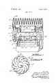
- FIG. 1is a side elevation of one embodiment of a device constructed in accordance with this invention, certain parts being shown in section;
- FIG. 2is a section taken along line 2-2 of FIG. 1;
- FIG. 3is a view generally similar to FIG. 1 showing the device during initial stages of inflation of the bag;
- FIG. 4is a view generally similar to FIG. 3 showing the device during final stages of inflation
- FIG. 5is a fragmentary side elevation of a second embodiment of this invention.
- FIG. 6is a fragmentary side elevation of a third embodiment of this invention.
- FIG. 7is a fragmentary side elevation of a fourth embodiment of this invention.
- FIG. 8is a bottom plan view of FIG. 7;
- FIG. 9is a side elevation of another embodiment of this invention.
- FIG. 10is a section taken generally along line 10-10 of FIG. 9.
- a gas generating and inflatable bag device constructed in accordance with this inventionis generally shown at l.
- the devicebasically includes a gas generating section or container 3, an inflatable bag or gas-confining means 5, and a nongaseous matter trap 7.
- device 1includes a housing 9 supporting generator 3.
- Generator 3has one or more compartments 11 therein in which propellant 13 is stored.
- Suitable ignition meansare provided for igniting the propellant in response to a signal from a sensor, indicative of a collision or deceleration of predetermined magnitude.
- the generator 3 and propellant 13form a gas source.
- a suitable rupturable membrane 15extends across the generator outlet to retain the propellant in the generator until the propellant is ignited and sufficient pressure developed to rupture the membrane.
- the propellantmay be of a type disclosed in copending application Ser. No. 746,333, i.e., black powder, which is adapted to ignite and react within a few milliseconds, releasing gas in the process.
- the generator 3, including propellant 13,thus constitutes an inflation means.
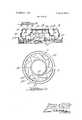
- Trap 7includes a housing 17 having a central cavity or passage 19 therein. Housings 9 and 17 are connected together by a plurality of fasteners 21 and 23.
- the central portion of passages 19is formed into a generally circular or looped material confining chamber or passage 25 by an inwardly extending ledge or shoulder 27, a directing means or deflector 29 at one end and a retaining ring 31 at the other end.
- the deflector 29includes a plate member 33 having a plurality of curved deflecting vanes 35 extending away from one side thereof.
- the deflecting vanes 35have a concave and a convex side with a radially inner end of each vane being located on a radially line relative to the center of the member 35 which is angularly separated from a radial line passing through the radially outer end of the vane, i.e., the inner and outer ends of each vane are angularly offset from one another. It is desirable that the vanes be so formed that any gas and other materials entering the space between the inner ends of two adjacent vanes are directed away from the deflector 29 in a direction which will cause the materials to travel outwardly to the outer wall of chamber 25 and thence along such wall around the chamber.
- the plate 33also has a generally cone-shaped diverting portion 37 extending away from the plate in the same direction as the vanes 35. Any gas or materials impinging on the cone are directed and deflected toward the vanes.
- the deflector 29is located over the gas generator 3 and covers the opening formed by ledge 27. Fasteners 39 extend through plate 33 and some of the vanes 35 into threaded holes in ledge 27 to secure the deflector to the housing 17.
- the chamber 25is preferably circular.
- the annular ring 31is clamped in a position adjacent the outlet from chamber 25 by clamping ring 41.
- the ring 31is seated on a shoulder 43.
- Ring 31has an annular recess or trough 45 opening toward chamber 25. Particles which move up the wall of chamber 25 as the particles travel around the chamber will eventually move into trough 45 where as discussed hereinafter, they will be trapped until they are consumed by combustion.
- a chamber 49may be connected to the discharge side of trap 7.
- Chamber 49may be filled with a supply of material, such as coolant, for example, adapted to react with the elements of combustion to affect the characteristics thereof.
- a materialsuch as disclosed in copending application Ser. No. 746,560, filed July 22, 1968, may be used if desired.
- Suitable retaining meanssuch as diaphragms 51 and 53 may be employed for retaining the material in the chamber 49.
- the inflatable bag 5is folded in a manner to provide a plurality of folds 55 therein located side by side and extending generally away from the gas generator 3.
- the outer edges of the bag 5are folded double and secured to the periphery of the device between two clamping rings 57 and 59.
- the clamping ringsare connected to the body 17 by conventional fasteners not shown.
- the propellantis initially ignited. Within a few milliseconds, a pressure sulficient to rupture the membrane or diaphragm is attained and the diaphragm ruptures.
- the pressure of the gas released in the generatorcauses the propellant undergoing combustion to be discharged or propelled upwardly toward the deflector 29.
- the combustible propellant and the gasare directed toward the vanes 35 by cone 37 and also as a result of the pressure built up in the space between generator 3 and deflector 29.
- the vanesdirect all of the materials passing through the section toward the wall of chamber 25 at a point angularly spaced from the point at which such material exits from the vaned section. This causes the materials to travel in a generally circular path after they reach the wall of the chamber. This also causes the materials undergoing combustion and the materials which are not yet undergoing combustion to mix, thereby enhancing combustion of the propellant.
- the gas passing through the vane section into the chamber 25is forced, due to the increase of pressure behind such gas, from the chamber and up through the opening in ring 31 and through the chamber 49 into the bag 5.
- chamber 49is provided with a supply of coolant material, for example, such coolant material will be mixed with the gas as the latter ruptures the diaphragms 53 and 51 and inflates the bag.
- the particles, globules and pieces of reacting propellant emerging from the vaned section of the deflector 29will move in a substantially straight line, due to their inertia, to the wall of chamber 25, and then travel around the wall of the chambers as they are consumed. Due to their mass and velocity the reacting particles are kept in the chamber until they are converted to gas. As more and more gas and reacting particles of propellant emanate from the deflector 29, and since some reacting particles may emanate from the deflector 29 on the path inclined upwardly relative to the ledge 27 and hence tend to spiral upwardly, many globules and particles may be forced and move upwardly along the wall of chamber 25 into the trough 45 where they are retained until they are converted to gas or until the bag is in an inflated condition.
- the device describedprevents particles or parts of the propellant from moving directly from the generator to an inflatable bag, the particles being caught in a trap until they are substantially converted to gas. Moreover, the deflector 29 and chamber 25 enhance thorough mixing and hence complete combustion of the propellant.
- Device 31aincludes an annular ring on plate 61 having a neck portion 63 extending toward and into chamber 25.
- An annular ring or plate 65is secured to the lower end of neck 63 and has an outer diameter greater than the outer diameter of the adjacent portion of neck 63 thereby providing a lip 67.
- the device 7acombines with the upper portion of chamber 25 to form a trapping trough for hot particles or globules of burning propellant.
- Device 31bis generally similar to device 31a except annular plate or ring 65 of device 31a is replaced by an annular plate 69 having a shoulder or flange 71 extending upwardly from the outer edge thereof. Both devices 310 and 31b provide retaining ledges for the retaining troughs 45.
- Device 310includes an annular portion 610 having a neck portion 63:: extending toward and into chamber 25.
- Device 310has a liquid trap formed in annular portion 61c.
- the liquid trapis formed by a screen matrix 32 preferably constructed of a plurality of layers of screen material.
- the matrix 32is located in an annular trough 34, the bottom of which has a plurality of elongated recesses 36 therein. Each recess has a plurality of holes 40 extending through the annular portion 61c.
- the screen matrix 32is secured in position by a plurality of fasteners 38.
- FIGS. 9 and 10Another embodiment of the gas generator and inflatable bag device is shown generally in FIGS. 9 and 10.
- the deviceincludes a gas generator section 3a having one or more compartments 11a therein for holding a supply of gas generating material, such as combustible propellant 13a.
- a suitable ignition means 73is provided for igniting the propellant 130.
- a diaphragm or membrane l5amay be provided between the outlet of the compartments 11a and the inlet of a chamber forming body 75.
- the body 75has one or more passages 77 therein which direct the products emanating from the gas generator 3a to a trap 7a.
- the passage or passages 77may be filled with material, such as coolant material for example, adapted to mix with, react and cool the gases of the propellant.
- a diaphragm 78may be provided for retaining material in the passages 77.
- trap 7acomprises two stampings 79 and 81 which together form the same functions as diffuser 29, chamber 25 and retaining member 31 of the embodiment shown in FlGS. 1-4.
- Stamping 79includes a cup-shaped portion which fits over generator 3a.
- the cup-shaped portion 80is integrally joined with a diffusing portion 83.
- Portion 83is formed by a first annular wall 85 integrally connected to a second annular wall 87, extending substantially perpendicular to wall 85, the walls 85 and 87 being cut along lines 89 and formed into diffusing vanes 91.
- Vanes 91will cause the materials entering on the inner side of portion 83 to be discharged from the portion 83 in a generally tangential direction into a chamber 250 formed by an annular wall 93.
- the materials discharged into chamber 25awill travel around the chamber with the heaviest materials being on the outside toward the wall 93.
- Stamping 81is secured to wall 93 by welding, for example, and includes a wall 95 which forms an extension of wall 93.
- An inwardly directed ring-shaped portion 97has a lip 99 thereon which aids in trapping particles or globules of molten propellant in the trap 7.
- the gas produced by the combustible processpasses out of the chamber 25 and begins inflation of the bag 5a As the particles and globules of combustible material are consumed by combustion, the gas released therefrom also escapes from the chamber 25a and enters the bag 5a. Should any of the materials move or be forced into the area adjacent annular ring 97, the lip 99 inhibits the escape of such material from the trap until consumed by combustion.
- An inflatable devicecomprising an inflation means, container means for holding said inflation means, an inflatable means connected to said container means, means for releasing said inflation means from said container means for inflating said inflatable means, and confining means adjacent said container means, said container means directing said inflation means into said confining means in a direction to enhance movement of said inflation means around said confining means, said container means including a gas generator body, said inflation means including propellant in said body adapted to release gas, said propellant being discharged from said generator in a gaseous state and a nongaseous state, said container means including directing means for causing heavier masses of said propellant to move to the outside of said confining means, said propellant in a gaseous state being permitted to escape from said confining means, said directing means comprising a plurality of vanes for directing all of said inflation means into said confining means in said direction to enhance movement of said inflation means therearound.
- said confining meanscomprise a generally loop-shaped chamber located in a plane generally perpendicular to the initial direction of flow of said inflation means.
- said confining meansfurther comprises a generally loop-shaped retaining means for inhibiting movement of said nongaseous inflation means out of said chamber.
- An inflatable device for an automotive vehiclecomprising an inflatable bag, means for generating gas for inflating said bag, said means including a reservoir, combustible propellant in said reservoir adapted upon combustion to release gas, some of said propellant being discharged from said reservoir in a nongaseous state, said gas and propellant in a nongaseous state moving in a first general direction upon being discharged from said reservoir, directing means for directing all of the gas and nongaseous propellant discharged from said reservoir into a plane of movement generally normal to said first direction, and confining means for inhibiting movement of said nongaseous propellant into said bag, said confining means comprising a generally loop-shaped chamber,
- said directing meanscomprises a plurality of vanes for directing said propellant into said chamber in a direction to enhance movement of said propellant therearound.
- An inflatable device for an automotive vehiclecomprising an inflatable bag, means for generating gas for inflating said bag, said means including a reservoir, combustible propeller in said reservoir adapted upon combustion to release gas, said gas being discharged from said reservoir, some of said propellant being discharged from said reservoir in a nongaseous state, confining means, directing means for directing the gas and nongaseous propellant discharged from said reservoir into said confining means, said confining means inhibiting movement of said nongaseous propellant into said bag, said confining means comprising a generally loop-shaped chamber, said directing means including a plurality of vanes for directing all of said propellant into said chamber in a direction to enhance movement of said propellant therearound, said chamber being generally loop-shaped, retaining means adjacent the outlet of said chamber, said retaining means including trough forming means generally loop-shaped in configuration and surrounding said outlet.
- An inflatable device for an automotive vehiclecomprising an inflatable bag, means for generating gas for inflating said bag, said means including a reservoir, combustible propellant in said reservoir adapted upon combustion to release gas, said gas being discharged from said reservoir, some of said propellant being discharged from said reservoir in a nongaseous state, confining means, directing means for directing the gas and nongaseous propellant discharged from said reservoir into said confining means, said confining means for inhibiting movement of said nongaseous propellant into said bag, said confining means comprising a generally loopshaped chamber, said directing means including a plurality of vanes for directing all of of said propellant into said chamber in a direction to enhance movement of said propellant therearound, said chamber being generally circular shape, retaining means adjacent the outlet of said chamber, said retaining means including trough forming means generally circular in shape, said trough forming means being spaced from the area of said confining means into which said propellant is directed by said vanes and surrounding said outlet.
Landscapes
- Engineering & Computer Science (AREA)
- Physics & Mathematics (AREA)
- Fluid Mechanics (AREA)
- Mechanical Engineering (AREA)
- General Engineering & Computer Science (AREA)
- Air Bags (AREA)
Abstract
Description
Claims (8)
Applications Claiming Priority (1)
| Application Number | Priority Date | Filing Date | Title |
|---|---|---|---|
| US87047069A | 1969-10-31 | 1969-10-31 |
Publications (1)
| Publication Number | Publication Date |
|---|---|
| US3618980Atrue US3618980A (en) | 1971-11-09 |
Family
ID=25355446
Family Applications (1)
| Application Number | Title | Priority Date | Filing Date |
|---|---|---|---|
| US870470AExpired - LifetimeUS3618980A (en) | 1969-10-31 | 1969-10-31 | Trap for nongaseous matter |
Country Status (1)
| Country | Link |
|---|---|
| US (1) | US3618980A (en) |
Cited By (32)
| Publication number | Priority date | Publication date | Assignee | Title |
|---|---|---|---|---|
| US3785149A (en)* | 1972-06-08 | 1974-01-15 | Specialty Prod Dev Corp | Method for filling a bag with water vapor and carbon dioxide gas |
| US3787074A (en)* | 1971-05-28 | 1974-01-22 | Allied Chem | Multiple pyro system |
| US3871684A (en)* | 1971-08-02 | 1975-03-18 | Dow Chemical Co | Gas generator |
| US3877882A (en)* | 1972-07-27 | 1975-04-15 | Talley Industries | Gas generating device |
| US3897285A (en)* | 1973-09-10 | 1975-07-29 | Allied Chem | Pyrotechnic formulation with free oxygen consumption |
| US3902934A (en)* | 1972-06-08 | 1975-09-02 | Specialty Products Dev Corp | Gas generating compositions |
| US3944251A (en)* | 1972-04-28 | 1976-03-16 | Specialty Products Development Corporation | Gas generator for automobile driver restraint bag |
| US3964255A (en)* | 1972-03-13 | 1976-06-22 | Specialty Products Development Corporation | Method of inflating an automobile passenger restraint bag |
| US3966226A (en)* | 1972-04-17 | 1976-06-29 | Eaton Corporation | Fluid supply for occupant restraint system |
| US4084839A (en)* | 1975-07-14 | 1978-04-18 | Nippon Soken, Inc. | Gas bag protection apparatus for vehicles |
| US4111457A (en)* | 1975-12-19 | 1978-09-05 | Bayerische Motoren Werke Ag | Inflatable restraining device for motor vehicles |
| US4114924A (en)* | 1975-07-11 | 1978-09-19 | Nippon Soken, Inc. | Inflatable bag apparatus for protecting occupants in vehicles |
| US4200615A (en)* | 1976-03-29 | 1980-04-29 | Allied Chemical Corporation | All-pyrotechnic inflator |
| US4455944A (en)* | 1980-12-12 | 1984-06-26 | Messerschmitt-Bolkow-Blohm Gmbh | Device for separating the solid charge residues in a pyrotechnic regulating unit |
| US4907819A (en)* | 1988-09-16 | 1990-03-13 | Talley Automotive Products, Inc. | Lightweight non-welded gas generator with rolled spun lip |
| US4923212A (en)* | 1988-08-17 | 1990-05-08 | Talley Automotive Products, Inc. | Lightweight non-welded inflator unit for automobile airbags |
| US5224734A (en)* | 1992-04-08 | 1993-07-06 | Daicel Chemical Industries, Ltd. | Gas generator for air bags having vertical stack arrangement |
| US5226561A (en)* | 1991-03-01 | 1993-07-13 | Oea, Inc. | Projectile for initiating inflation of a motor vehicle inflatable safety system |
| US5230531A (en)* | 1990-10-22 | 1993-07-27 | Oea, Inc. | Gas generator ignition assembly using a projectile |
| WO1993021036A1 (en)* | 1992-04-08 | 1993-10-28 | Daicel Chemical Industries, Ltd. | Air bag having double-wall construction |
| WO1993021039A1 (en)* | 1992-04-08 | 1993-10-28 | Daicel Chemical Industries, Ltd. | Gas generator for air bags with circumferentially disposed blades |
| WO1993021037A1 (en)* | 1992-04-08 | 1993-10-28 | Daicel Chemical Industries, Ltd. | Air bag with inflatable ribs |
| US5366239A (en)* | 1993-09-27 | 1994-11-22 | Trw Inc. | Air bag inflator assembly |
| US5419875A (en)* | 1992-04-08 | 1995-05-30 | Daicel Chemical Industries, Ltd. | Gas generator with novel nozzle structure |
| WO1997000794A1 (en)* | 1995-06-22 | 1997-01-09 | Dynamit Nobel Gmbh Explosivstoff- Und Systemtechnik | Gas generator for airbag systems with a centrifugal dust separator |
| US5624134A (en)* | 1992-04-15 | 1997-04-29 | Daicel Chemical Industries, Inc. | Gas generator formed with electron beam welding |
| US5692768A (en)* | 1991-10-21 | 1997-12-02 | Trw Vehicle Safety Systems Inc. | Airbag assembly |
| US6390499B1 (en)* | 1997-09-02 | 2002-05-21 | Autoliv Development Ab | Gas bag arrangement with a gas guide housing comprising partial discharge areas |
| US20060028008A1 (en)* | 2004-08-05 | 2006-02-09 | Trw Automotive Safety Systems Gmbh | Gas bag module for a vehicle occupant restraint device |
| US20080258438A1 (en)* | 2005-10-17 | 2008-10-23 | Takata-Petri Ag | Airbag module for a motor vehicle |
| US20160229372A1 (en)* | 2013-09-19 | 2016-08-11 | Key Safety Systems, Inc. | Inflator with Flow Wash Strainer |
| US20160375390A1 (en)* | 2015-06-25 | 2016-12-29 | Tm Industrial Supply, Inc. | Horizontal Coalescing Filter |
Citations (9)
| Publication number | Priority date | Publication date | Assignee | Title |
|---|---|---|---|---|
| US295322A (en)* | 1884-03-18 | Xtohjst columbus albbecht | ||
| US2850291A (en)* | 1957-10-03 | 1958-09-02 | William B Jaspert | Protective devices for passengers in moving vehicles |
| US2985104A (en)* | 1955-01-03 | 1961-05-23 | Phillips Petroleum Co | Improved cartridge for producing gas |
| US3066014A (en)* | 1958-04-18 | 1962-11-27 | Hycon Mfg Company | Cool gas generator |
| US3336045A (en)* | 1965-06-19 | 1967-08-15 | Kobori Yasusaburo | Safety devices for vehicles |
| US3477740A (en)* | 1967-09-20 | 1969-11-11 | Eaton Yale & Towne | Vehicle safety apparatus |
| US3516685A (en)* | 1967-11-08 | 1970-06-23 | Eaton Yale & Towne | Inflatable confinement vehicle safety apparatus |
| US3532360A (en)* | 1968-07-22 | 1970-10-06 | Chrysler Corp | Gas generating apparatus for vehicle safety device |
| US3532359A (en)* | 1968-07-22 | 1970-10-06 | Chrysler Corp | Inflatable device |
- 1969
- 1969-10-31USUS870470Apatent/US3618980A/ennot_activeExpired - Lifetime
Patent Citations (9)
| Publication number | Priority date | Publication date | Assignee | Title |
|---|---|---|---|---|
| US295322A (en)* | 1884-03-18 | Xtohjst columbus albbecht | ||
| US2985104A (en)* | 1955-01-03 | 1961-05-23 | Phillips Petroleum Co | Improved cartridge for producing gas |
| US2850291A (en)* | 1957-10-03 | 1958-09-02 | William B Jaspert | Protective devices for passengers in moving vehicles |
| US3066014A (en)* | 1958-04-18 | 1962-11-27 | Hycon Mfg Company | Cool gas generator |
| US3336045A (en)* | 1965-06-19 | 1967-08-15 | Kobori Yasusaburo | Safety devices for vehicles |
| US3477740A (en)* | 1967-09-20 | 1969-11-11 | Eaton Yale & Towne | Vehicle safety apparatus |
| US3516685A (en)* | 1967-11-08 | 1970-06-23 | Eaton Yale & Towne | Inflatable confinement vehicle safety apparatus |
| US3532360A (en)* | 1968-07-22 | 1970-10-06 | Chrysler Corp | Gas generating apparatus for vehicle safety device |
| US3532359A (en)* | 1968-07-22 | 1970-10-06 | Chrysler Corp | Inflatable device |
Cited By (40)
| Publication number | Priority date | Publication date | Assignee | Title |
|---|---|---|---|---|
| US3787074A (en)* | 1971-05-28 | 1974-01-22 | Allied Chem | Multiple pyro system |
| US3871684A (en)* | 1971-08-02 | 1975-03-18 | Dow Chemical Co | Gas generator |
| US3964255A (en)* | 1972-03-13 | 1976-06-22 | Specialty Products Development Corporation | Method of inflating an automobile passenger restraint bag |
| US3966226A (en)* | 1972-04-17 | 1976-06-29 | Eaton Corporation | Fluid supply for occupant restraint system |
| US3944251A (en)* | 1972-04-28 | 1976-03-16 | Specialty Products Development Corporation | Gas generator for automobile driver restraint bag |
| US3785149A (en)* | 1972-06-08 | 1974-01-15 | Specialty Prod Dev Corp | Method for filling a bag with water vapor and carbon dioxide gas |
| US3902934A (en)* | 1972-06-08 | 1975-09-02 | Specialty Products Dev Corp | Gas generating compositions |
| US3877882A (en)* | 1972-07-27 | 1975-04-15 | Talley Industries | Gas generating device |
| US3897285A (en)* | 1973-09-10 | 1975-07-29 | Allied Chem | Pyrotechnic formulation with free oxygen consumption |
| US4114924A (en)* | 1975-07-11 | 1978-09-19 | Nippon Soken, Inc. | Inflatable bag apparatus for protecting occupants in vehicles |
| US4084839A (en)* | 1975-07-14 | 1978-04-18 | Nippon Soken, Inc. | Gas bag protection apparatus for vehicles |
| US4111457A (en)* | 1975-12-19 | 1978-09-05 | Bayerische Motoren Werke Ag | Inflatable restraining device for motor vehicles |
| US4200615A (en)* | 1976-03-29 | 1980-04-29 | Allied Chemical Corporation | All-pyrotechnic inflator |
| US4455944A (en)* | 1980-12-12 | 1984-06-26 | Messerschmitt-Bolkow-Blohm Gmbh | Device for separating the solid charge residues in a pyrotechnic regulating unit |
| US4923212A (en)* | 1988-08-17 | 1990-05-08 | Talley Automotive Products, Inc. | Lightweight non-welded inflator unit for automobile airbags |
| US4907819A (en)* | 1988-09-16 | 1990-03-13 | Talley Automotive Products, Inc. | Lightweight non-welded gas generator with rolled spun lip |
| US5230531A (en)* | 1990-10-22 | 1993-07-27 | Oea, Inc. | Gas generator ignition assembly using a projectile |
| US5226561A (en)* | 1991-03-01 | 1993-07-13 | Oea, Inc. | Projectile for initiating inflation of a motor vehicle inflatable safety system |
| US5692768A (en)* | 1991-10-21 | 1997-12-02 | Trw Vehicle Safety Systems Inc. | Airbag assembly |
| WO1993021039A1 (en)* | 1992-04-08 | 1993-10-28 | Daicel Chemical Industries, Ltd. | Gas generator for air bags with circumferentially disposed blades |
| WO1993021036A1 (en)* | 1992-04-08 | 1993-10-28 | Daicel Chemical Industries, Ltd. | Air bag having double-wall construction |
| WO1993021037A1 (en)* | 1992-04-08 | 1993-10-28 | Daicel Chemical Industries, Ltd. | Air bag with inflatable ribs |
| US5260038A (en)* | 1992-04-08 | 1993-11-09 | Daicel Chemical Industries, Ltd. | Gas generator for air bags with circumferentially disposed blades |
| US5338061A (en)* | 1992-04-08 | 1994-08-16 | Daicel Chemical Industries, Ltd. | Air bag having double-wall construction |
| US5372381A (en)* | 1992-04-08 | 1994-12-13 | Daicell Chemical Industries, Ltd. | Air bag with inflatabe ribs |
| US5419875A (en)* | 1992-04-08 | 1995-05-30 | Daicel Chemical Industries, Ltd. | Gas generator with novel nozzle structure |
| US5224734A (en)* | 1992-04-08 | 1993-07-06 | Daicel Chemical Industries, Ltd. | Gas generator for air bags having vertical stack arrangement |
| US5624134A (en)* | 1992-04-15 | 1997-04-29 | Daicel Chemical Industries, Inc. | Gas generator formed with electron beam welding |
| US5366239A (en)* | 1993-09-27 | 1994-11-22 | Trw Inc. | Air bag inflator assembly |
| WO1997000794A1 (en)* | 1995-06-22 | 1997-01-09 | Dynamit Nobel Gmbh Explosivstoff- Und Systemtechnik | Gas generator for airbag systems with a centrifugal dust separator |
| US6390499B1 (en)* | 1997-09-02 | 2002-05-21 | Autoliv Development Ab | Gas bag arrangement with a gas guide housing comprising partial discharge areas |
| US20060028008A1 (en)* | 2004-08-05 | 2006-02-09 | Trw Automotive Safety Systems Gmbh | Gas bag module for a vehicle occupant restraint device |
| EP1623889A3 (en)* | 2004-08-05 | 2006-09-20 | TRW Automotive Safety Systems GmbH | Airbag module for a vehicle occupant restraint device |
| US7559574B2 (en) | 2004-08-05 | 2009-07-14 | Trw Automotive Safety Systems Gmbh | Gas bag module for a vehicle occupant restraint device |
| US20080258438A1 (en)* | 2005-10-17 | 2008-10-23 | Takata-Petri Ag | Airbag module for a motor vehicle |
| US7686329B2 (en)* | 2005-10-17 | 2010-03-30 | Takata-Petri Ag | Airbag module for a motor vehicle |
| US20160229372A1 (en)* | 2013-09-19 | 2016-08-11 | Key Safety Systems, Inc. | Inflator with Flow Wash Strainer |
| US9873403B2 (en)* | 2013-09-19 | 2018-01-23 | Key Safety Systems, Inc. | Inflator with flow wash strainer |
| US20160375390A1 (en)* | 2015-06-25 | 2016-12-29 | Tm Industrial Supply, Inc. | Horizontal Coalescing Filter |
| US10792604B2 (en)* | 2015-06-25 | 2020-10-06 | Tm Industrial Supply, Inc. | Horizontal coalescing filter |
Similar Documents
| Publication | Publication Date | Title |
|---|---|---|
| US3618980A (en) | Trap for nongaseous matter | |
| US3618981A (en) | Inflatable device | |
| US5199740A (en) | Hybrid inflator for air bag | |
| KR950013723B1 (en) | Air bag inflator | |
| US3877882A (en) | Gas generating device | |
| US3984126A (en) | Inflator for vehicle occupant restraint system | |
| US5033772A (en) | Hybrid inflator | |
| US5527067A (en) | Gas generator formed with electron beam welding | |
| US3960390A (en) | Inflator | |
| US3618976A (en) | Inflatable bag and gas diffusing device | |
| US5533751A (en) | Hybrid inflator with elongated housing and center discharge | |
| US5364127A (en) | Inflator assembly | |
| US3532359A (en) | Inflatable device | |
| JP3019856U (en) | Airbag inflator and filter for inflator | |
| US5338061A (en) | Air bag having double-wall construction | |
| JP2609404B2 (en) | Igniters and expanders | |
| US5423570A (en) | Hybrid inflator with tortuous delivery passage | |
| US6010153A (en) | Hybrid inflator for airbags | |
| US3871684A (en) | Gas generator | |
| KR0179997B1 (en) | Apparatus for inflating an inflatable vehicle occupant restraint | |
| JP3038714U (en) | Built-in charge detonator for inflators | |
| JPH0357747A (en) | Inflatable device for vehicle inflatable impact protection bag | |
| JPS6349659B2 (en) | ||
| US6139055A (en) | Adaptive heated stage inflator | |
| US5260038A (en) | Gas generator for air bags with circumferentially disposed blades |
Legal Events
| Date | Code | Title | Description |
|---|---|---|---|
| AS | Assignment | Owner name:FIDELITY UNION TRUST COMPANY, TRUSTEE,NEW JERSEY Free format text:MORTGAGE;ASSIGNOR:CHRYSLER CORPORATION;REEL/FRAME:003832/0358 Effective date:19810209 Owner name:FIDELITY UNION TRUST COMPANY, 765 BROAD ST., NEWAR Free format text:MORTGAGE;ASSIGNOR:CHRYSLER CORPORATION;REEL/FRAME:003832/0358 Effective date:19810209 | |
| AS | Assignment | Owner name:CHRYSLER CORPORATION, HIGHLAND PARK, MI 12000 LYNN Free format text:ASSIGNORS HEREBY REASSIGN, TRANSFER AND RELINQUISH THEIR ENTIRE INTEREST UNDER SAID INVENTIONS AND RELEASE THEIR SECURITY INTEREST.;ASSIGNORS:FIDELITY UNION BANK;ARNEBECK, WILLIAM, INDIVIDUAL TRUSTEE;REEL/FRAME:004063/0604 Effective date:19820217 | |
| AS | Assignment | Owner name:CHRYSLER CORPORATION Free format text:PARTES REASSIGN, TRANSFER AND RELINQUISH THEIR ENTIRE INTEREST UNDER SAID PATENTS ALSO RELEASE THEIR SECURITY INTEREST.;ASSIGNOR:MANUFACTURERS NATIONAL BANK OF DETROIL (CORPORATE TRUSTEE) AND BLACK DONALD E., (INDIVIDUAL TRUSTEE);REEL/FRAME:004355/0154 Effective date:19840905 |