US3515873A - Method and apparatus for analyzing and calibrating radiation beams of x-ray generators - Google Patents
Method and apparatus for analyzing and calibrating radiation beams of x-ray generatorsDownload PDFInfo
- Publication number
- US3515873A US3515873AUS697233AUS3515873DAUS3515873AUS 3515873 AUS3515873 AUS 3515873AUS 697233 AUS697233 AUS 697233AUS 3515873D AUS3515873D AUS 3515873DAUS 3515873 AUS3515873 AUS 3515873A
- Authority
- US
- United States
- Prior art keywords
- generator
- oscilloscope
- traces
- calibrating
- analyzing
- Prior art date
- Legal status (The legal status is an assumption and is not a legal conclusion. Google has not performed a legal analysis and makes no representation as to the accuracy of the status listed.)
- Expired - Lifetime
Links
Images

Classifications
- G—PHYSICS
- G01—MEASURING; TESTING
- G01T—MEASUREMENT OF NUCLEAR OR X-RADIATION
- G01T1/00—Measuring X-radiation, gamma radiation, corpuscular radiation, or cosmic radiation
- G01T1/16—Measuring radiation intensity
- G01T1/24—Measuring radiation intensity with semiconductor detectors
- G01T1/247—Detector read-out circuitry
- G—PHYSICS
- G01—MEASURING; TESTING
- G01T—MEASUREMENT OF NUCLEAR OR X-RADIATION
- G01T7/00—Details of radiation-measuring instruments
- G01T7/005—Details of radiation-measuring instruments calibration techniques
- H—ELECTRICITY
- H05—ELECTRIC TECHNIQUES NOT OTHERWISE PROVIDED FOR
- H05G—X-RAY TECHNIQUE
- H05G1/00—X-ray apparatus involving X-ray tubes; Circuits therefor
- H05G1/08—Electrical details
- H05G1/26—Measuring, controlling or protecting
Definitions
- the inventioncomprises a portable apparatus which A accomplished.
- the apparatusincludes a combination of a radiation detector preamplifying assembly compactly arranged in a box-like housing and with a cable carrying conductors extending from the housing to a power supply and to a dual sweep oscilloscope.
- the preamplifying assemblyincludes a pair of semiconductor detector elements, one of which is relatively partially shielded to the radiation "beam, the other of which is relatively non-shielded. The respective signals from the detector elements are amplified and transmitted simultaneously to the oscilloscope while the elements are subjected to the beam of radiation.
- the method of calibrationincludes providing a graph, or a photograph of a pair of traces on the oscilloscope, representative of a properly calibrated generator, and then observing the ratio of pulse heights shown on the oscilloscope while a generator under calibration is being operated, and finally adjusting such generator until the percent of transmission through the respective detector elements coincides with a standard peak voltage indicated by the graph or until the traces on the oscilloscope coincide with the traces shown on the photograph.
- the graph or the photographare prepared using the same apparatus which is later used in calibrating other generators to the predetermined standard. Observation of the traces on the oscilloscope, or of photographs made of the same, provide information from which malfunctioning of the generator may :be deduced.
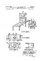
- FIG. 1is a diagrammatic view indicating a typical usage of the invention.
- FIG. 2is a top plan view of the housing for the preamplifying assembly, with the top cover removed, and with the detector elements and the amplifier mounts shown schematically.
- FIG. 2Ais an inside view of the cover for the housing of FIG. 2.
- FIG. 2Bis a side elevation view of the bottom plate for the housing of FIG. 2.
- FIG. 3is a wiring diagram for the assembly contained in the housing.
- FIG. 4is a view of the oscilloscope graticule showing traces similar to those of a properly calibrated and operating generator.
- FIG. 4Ais a view of the graticule showing traces deviating from a properly operating generator and illustrating a situation wherein a faulty high voltage rectifier is present, and
- FIG. 5is a graph for reference to determine the peak voltage of the calibrated machine following an inspection of the traces such as indicated in FIG. 4.
- a conventional X-ray generator indicated generally at 10is mounted for movement above a table 11 on which a patient is to be placed.
- a portable apparatuspreferably in the form of a vehicular support, includes a conventional dual sweep oscilloscope 12, a conventional decade type glow tube timing means 13, a camera 14 preferably of the Polaroid type pivotally mounted adjacent the graticule of the oscilloscope, a
- a cable 18 having a length suflicient to displace the operator at a safe distance from the radiation beamextends from the assembly 16 to the power supply.
- the oscilloscope which forms a significant feature of the combination of apparatusmay be of any conventional type, as for example the Type 545B dual sweep oscilloscope available from Tektronix Inc., Beaverton, Oregon,
- the housing for the preamplifying assemblycomprises a generally rightparallelepiped form of box having a side plate 20 with an integral side wall 21 through which cable 18 extends, and with the plate 20 providing support for block structures indicated at 22, 23 and serving as the mounting of the operational amplifiers, later to be described.
- Mounted side by side at a suitable spacing, for example about 1.5 cm., and supported from plate 20 in any suitable mannerare a first detector element 24 and a second detector element 25, the latter being shielded by a suitable sheet 26 of beam filtering material such as aluminum.
- Another member providin walls 27, 28 for the boxis adapted to engage with plate 20 and wall 21 when the box is assembled.
- a bottom plate 29 having a pair of threaded rods 30, 31 projecting upwardly therefromis adapted to abut against the lower ends of the box walls, and the rods are adapted to extend through holes in the top plate 32 and to be engaged by nuts or other fastening means disposed on the upper surface of the top plate.
- Afiixed to the inside surface of the top plateis a sheet 33 of shielding material such as lead and projecting inwardly from the top plate is a U-shaped wall 34 of similar shielding material which is adapted to prevent backscatter into the detector elements.
- the sheet 33has an opening therein corresponding to the confines of wall 34 thus to provide a window 35 through which the beam passes and which window is covered by the outer layer of top plate material.
- the walls, bottom and top plateare constructed of thin gauge aluminum sheet.
- the preamplifying apparatusincludes the detectors 24 and 25 comprising semi-conductor detector elements of the lithium-ion-drift type, such as type 5X5-LID-1000-100A available from Solid State Radiations, Inc., Los Angeles, Calif, and which are fed in parallel at a suitable positive DC. voltage from power supply 15. As radiant energy is absorbed in the depletion layer of these detectors their resistance is decreased and they can be used to develop an electrical signal proportional to the absorbed radiant energy.
- the detectors 24 and 25comprising semi-conductor detector elements of the lithium-ion-drift type, such as type 5X5-LID-1000-100A available from Solid State Radiations, Inc., Los Angeles, Calif, and which are fed in parallel at a suitable positive DC. voltage from power supply 15. As radiant energy is absorbed in the depletion layer of these detectors their resistance is decreased and they can be used to develop an electrical signal proportional to the absorbed radiant energy.
- the two detectorsare substantially identical as regards their ratings and their construction, and both have a high quiescent impedence, for example about 10 megaohrnsv
- voltage dividers 40Aare interposed and the signals developed at the load resistors which, for example, have a rating of 1 megaohm, are coupled directly into operational amplifiers 41, 41A connected as voltage followers.
- operational amplifiers 41, 41Aconnected as voltage followers.
- a signal ranging from about 0.1 volt for low PKV- low MA radiation to about 2.5 volts at high PKVhigh MA radiation of the generator 10can be developed and transmitted to the oscilloscope through conductors 42 and 42A.
- the operational amplifiersare of a suitable type such as the SQ-l 0A units available from Nexus Reserach Laboratory, lnc., Canton, Mass.
- Feedback loops 45, 45Aprovide linear, consistent and distortion-free amplification of signals.
- Conductors 46, 46A leading to the power supplycarry suit able current, for example, at about +15 volt DC, to the amplifiers as do conductors 47, 47A carrying about 15 volt DC. and conductor 48 carrying 0 to -15 volt D.C.
- Suitable control means on the power supplyserve to regulate the settings of the respective potentiometers and variable resistors.
- the entire preamplifying assemblycan be housed in a box as described having dimensions of about three to two by one inches.
- a preferred usage of the inventioninvolves the prior preparation of a reference graph such as shown in FIG. 5 representative of the radiation absorption characteristics of the detector element combination and wherein the abscissa represents the peak generating voltages in kilovolts of radiation beams used in diagnostic radiology, and the ordinate represents the transmission of the beam through added absorber 26 as a ratio of the output signal of the shielded or first detector 25 so that of the nonshielded or second detector 24.
- the relative heights of the traces 50, 51 (FIG. 4) shown on the graticule 52 of the oscilloscopeare determined and the ratio as a percent of transmission is plotted for the corresponding peak kilovoltage thereby to form a curve 53 for future reference.
- a photograph of the traces shown on the oscilloscopeis taken by camera 14 to provide a permanent record of a properly calibrated and functioning generator against which comparisons with other generators may be made.
- the photographserves further purposes in that it indicates waveform of the signals which upon analysis can be used to detect actual or incipient malfunctioning of the generator.
- the number of individual pulses indicative of the time of an exposureis displayed along the X-axis of the oscilloscope graticule.
- the time of the exposureis determined by counting the pulses on the oscilloscope or by the decade readout tubes of the unit 13 which show the number of impulses in any exposure. Normally, in a full wave, rectified, single phase unit type of generator there will be pulses per second.
- the timer of the generatorwill then be adjusted as part of its calibration.
- the generatorin the event that the milliamperage of the radiation beam, which can be determined by known calculations from the amplitude of either of traces 50, 51 shown on the oscilloscope, should depart from the proper value as indicated by comparison with a trace from the standard calibrated generator, then the generator likewise will be adjusted in known manner.
- the oscilloscope traces from a generator being testedserve to indicate to a skilled technician the type of abnormality which may be present in that generator. For example, as shown in FIG. 4A, the 'dilference in heights of successive pulses and the displacement of the traces downwardly on the graticule is indicative of a faulty high voltage rectifier in the generator. The fact that four pulses, however, are shown on the trace would indicate that the timer of the generator is operating satisfactorily.
- the apparatus embodying the inventionis particularly well suited for carrying out the described method steps.
- Camera 14is pivotally mounted adjacent the graticule of the oscilloscope and when a photographic record of the traces is desired, it is moved into and clamped in operating position for rapidly taking the record.
- Use of a camera such as the Polaroid typepermits the operator to obtain a permanent record in a short time.
- the entire apparatusmoreover, is self-contained except for the readily detachable power conductors 17, and may be easily moved from one generator to another in a hospital, and into and out of storage.
- the method of calibrating an X-ray generator to secure a standard peak voltage of its radiation beamcomprising, passing said beam simultaneously through a relatively partially shielded preamplifying detector element and through a substantially similar but relatively nonshielded detector element, depicting as exposure-rate time functions the output signals from said elements in the form of respective first and second traces simultaneously on an oscilloscope graticule, determining the ratio of the pulse height of said first to said second trace, and adjusting the generator until said ratio corresponds to a predetermined standard value.
- the method of calibrating an X-ray generator to secure a standard peak voltage of its radiation beamcomprising, providing as a standard a comparative photograph of the traces of a dual sweep oscilloscope showing small and large signal outputs as exposure-rate time functions derived from passing a beam from a suitably calibrated X-ray generator simultaneously and respectively through a relatively partially shielded preamplifying detector element and through a substantially similar but relatively non-shielded preamplifying detector element,
- a portable apparatuscomprising a radiation detector preamplifying assembly, a dual sweep oscilloscope, and a power supply for said assembly; said preamplifying assembly including a housing adapted to be located in the beam of said generator and containing a second detector element relatively partially shielded to said beam and a first detector element substantially similar to said first element but relatively non-shielded to said beam, and means for transmitting the respective small and large signal outputs as exposure-rate time functions from said detector elements, when subjected to said beam of radiation, to said oscilloscope to provide simultaneous traces on the graticule thereof, whereby the value of the peak voltage of said generator may be readily determined as a function of the ratio of the small to the large pulse heights shown by the oscilloscope traces.
- said housingencloses a pair of substantially similar operational amplifiers receiving signals from the respective detector elements and feeding said signals in amplified form to said oscilloscope through a cable extending through one side wall of said housing.
Landscapes
- Health & Medical Sciences (AREA)
- Physics & Mathematics (AREA)
- Life Sciences & Earth Sciences (AREA)
- General Physics & Mathematics (AREA)
- High Energy & Nuclear Physics (AREA)
- Molecular Biology (AREA)
- Spectroscopy & Molecular Physics (AREA)
- General Health & Medical Sciences (AREA)
- Toxicology (AREA)
- Measurement Of Radiation (AREA)
Description
June 2, 1970 HI ms ET AL 3,515,873
METHOD AND APPARATUS FOR ANALYZING AND CALIBRATING RADIATION BEAMS OF X-RAY GENERATORS Filed Jan. 11, 1968' a Sheets-Sheet 1 I 1-1 so 29 "l1 'li IETZA 35728 A INVENTORS EDWARD M. mssms HAROLD D. ROSENBAUM WALDO D. DEVORE M1,? M A ORNEY 'Jun 2, 1970 ADIATION E. M. HIGGINS T L 7 METHOD AND APPARATUS FOR ANALYZING AND CALIBRATING R BEAMS OF X-RAY GENERATORS 2 Sheets-Sheet 2 Filed Jan. 11, 1968 n Y O E m M m .w W ME m 5 s WW MA 3 EVW 5 1 A v m ID i lm MDOZ Dnu AQL Z0.w .m24r o O W A A m m .ZI .IIIII.II
United States Patent 3,515,873 METHOD AND APPARATUS FOR ANALYZING AND CALIBRATING RADIATION BEAMS 0F X-RAY GENERATORS Edward M. Higgins, Harold D. Rosenbaum, and Waldo D. De Vore, Lexington, Ky., assignors to The University of Kentucky Research Foundation, Lexington, Ky., a corporation of Kentucky Filed Jan. 11, 1968, Ser. No. 697,233 Int. Cl. G01t 1/24 US. Cl. 25083.3 4 Claims ABSTRACT OF THE DISCLOSURE A method for calibrating an X-ray generator by passing its radiation beam through two semi-conductor detector elements, one of which is partially shielded to the beam and the other of which is unshielded, the outputs of the detector elements being depicted simultaneously as separate traces on an oscilloscope. The generator is adjusted until the traces substantially coincide with standard traces taken on a suitably calibrated generator whose beam has previously passed through the same detector elements. An apparatus for use in carrying out the method is disclosed.
BACKGROUND OF THE INVENTION Field of the invention Radiology departments of hospitals frequently have several X-ray machines which are used interchangeably. It is desirable that all such machines, regardless of their make, be used in a uniformly calibrated condition so that radiographs of identical density and contrast may be secured. Kilovoltage variations among X-ray machines should be especially minimized not only because of resulting variations in quality of the beams, but also because of variations in the radiation output. As is known, the output is approximately a function of the square of the voltage. Although present day X-ray film has been improved to a point where a small change in exposure does not significantly change the radiograph density, the lati tude of exposure change still is not great enough to permit use of improperly calibrated machines with the result that in some instances repeated examinations of the patient have been necessitated due to lack of proper calibration.
Description of the prior art Manufacturers of conventional X-ray generators gen erally supply calibration data with the machine, and technicians employ voltage and current indicating meters to adjust the machine into conformity with such data during the initial calibration of the machine at the hospital. However, this does not signify that a plurality of generators calibrated according to factory specifications will have, or will retain, the same output of beam energy. For exam ple, a weak or gassy valve in the machine, relay contact bounce, faulty rectifiers, dirty contacts and other electrical faults in the generator will influence the quality and output of the beam, as will variations of power in the transmission line and transformers serving the machine. It is a purpose of the present invention to reduce substantially, if not to overcome completely, handicaps of the above mentioned nature in connection with the calibration and use of X-ray generators.
SUMMARY OF THE INVENTION The invention comprises a portable apparatus which A accomplished. The apparatus includes a combination of a radiation detector preamplifying assembly compactly arranged in a box-like housing and with a cable carrying conductors extending from the housing to a power supply and to a dual sweep oscilloscope. The preamplifying assembly includes a pair of semiconductor detector elements, one of which is relatively partially shielded to the radiation "beam, the other of which is relatively non-shielded. The respective signals from the detector elements are amplified and transmitted simultaneously to the oscilloscope while the elements are subjected to the beam of radiation.
The method of calibration includes providing a graph, or a photograph of a pair of traces on the oscilloscope, representative of a properly calibrated generator, and then observing the ratio of pulse heights shown on the oscilloscope while a generator under calibration is being operated, and finally adjusting such generator until the percent of transmission through the respective detector elements coincides with a standard peak voltage indicated by the graph or until the traces on the oscilloscope coincide with the traces shown on the photograph. The graph or the photograph are prepared using the same apparatus which is later used in calibrating other generators to the predetermined standard. Observation of the traces on the oscilloscope, or of photographs made of the same, provide information from which malfunctioning of the generator may :be deduced.
Among the objects of the invention are the provision of a reliable, safe and portable apparatus which can be used in X-ray generator calibrating and the provision of a method for analyzing and for calibrating the radiation beams of a number of such generators.
BRIEF DESCRIPTION OF THE DRAWINGS The objects of the invention will become more apparent as the description proceeds and when considered in conjunction with the accompanying drawings in which:
FIG. 1 is a diagrammatic view indicating a typical usage of the invention.
FIG. 2 is a top plan view of the housing for the preamplifying assembly, with the top cover removed, and with the detector elements and the amplifier mounts shown schematically.
FIG. 2A is an inside view of the cover for the housing of FIG. 2.
FIG. 2B is a side elevation view of the bottom plate for the housing of FIG. 2.
FIG. 3 is a wiring diagram for the assembly contained in the housing.
FIG. 4 is a view of the oscilloscope graticule showing traces similar to those of a properly calibrated and operating generator.
FIG. 4A is a view of the graticule showing traces deviating from a properly operating generator and illustrating a situation wherein a faulty high voltage rectifier is present, and
FIG. 5 is a graph for reference to determine the peak voltage of the calibrated machine following an inspection of the traces such as indicated in FIG. 4.
DESCRIPTION OF THE PREFERRED EMBODIMENT Referring first to FIG. 1, a conventional X-ray generator indicated generally at 10 is mounted for movement above a table 11 on which a patient is to be placed. A portable apparatus, preferably in the form of a vehicular support, includes a conventionaldual sweep oscilloscope 12, a conventional decade type glow tube timing means 13, acamera 14 preferably of the Polaroid type pivotally mounted adjacent the graticule of the oscilloscope, a
power supply for a preamplifying assembly 16, and conventional conductors 17 for electricity supplied to the timer and to the oscilloscope. Acable 18 having a length suflicient to displace the operator at a safe distance from the radiation beam extends from the assembly 16 to the power supply.
The oscilloscope which forms a significant feature of the combination of apparatus may be of any conventional type, as for example the Type 545B dual sweep oscilloscope available from Tektronix Inc., Beaverton, Oregon,
and having a conventional graticule on which the output signals derived from the preamplifying assembly, later to be described, will be simultaneously depicted.
As seen in FIGS. 2 to 2B, the housing for the preamplifying assembly comprises a generally rightparallelepiped form of box having aside plate 20 with anintegral side wall 21 through whichcable 18 extends, and with theplate 20 providing support for block structures indicated at 22, 23 and serving as the mounting of the operational amplifiers, later to be described. Mounted side by side at a suitable spacing, for example about 1.5 cm., and supported fromplate 20 in any suitable manner are afirst detector element 24 and asecond detector element 25, the latter being shielded by asuitable sheet 26 of beam filtering material such as aluminum. Another member providinwalls 27, 28 for the box is adapted to engage withplate 20 andwall 21 when the box is assembled. Abottom plate 29 having a pair of threadedrods top plate 32 and to be engaged by nuts or other fastening means disposed on the upper surface of the top plate. Afiixed to the inside surface of the top plate is a sheet 33 of shielding material such as lead and projecting inwardly from the top plate is a U-shapedwall 34 of similar shielding material which is adapted to prevent backscatter into the detector elements. The sheet 33 has an opening therein corresponding to the confines ofwall 34 thus to provide awindow 35 through which the beam passes and which window is covered by the outer layer of top plate material. Preferably the walls, bottom and top plate are constructed of thin gauge aluminum sheet.
Passing now to FIG. 3 the preamplifying apparatus includes thedetectors power supply 15. As radiant energy is absorbed in the depletion layer of these detectors their resistance is decreased and they can be used to develop an electrical signal proportional to the absorbed radiant energy. The two detectors are substantially identical as regards their ratings and their construction, and both have a high quiescent impedence, for example about 10 megaohrnsv In the load circuit of thedetectors voltage dividers 40A are interposed and the signals developed at the load resistors which, for example, have a rating of 1 megaohm, are coupled directly intooperational amplifiers 41, 41A connected as voltage followers. Depending upon the distance D (FIG. 1) between the X-ray generator and the housing 16 a signal ranging from about 0.1 volt for low PKV- low MA radiation to about 2.5 volts at high PKVhigh MA radiation of thegenerator 10 can be developed and transmitted to the oscilloscope throughconductors
Provision is made for individual zeroing of each operational amplifier bysuitable potentiometers 43, 43A, and variable resistors 44, 44A are employed to trim these amplifiers.Feedback loops 45, 45A provide linear, consistent and distortion-free amplification of signals.Conductors conductors conductor 48 carrying 0 to -15 volt D.C. Suitable control means on the power supply serve to regulate the settings of the respective potentiometers and variable resistors. The entire preamplifying assembly can be housed in a box as described having dimensions of about three to two by one inches.
METHOD OF ANALYZING AND CALIBRATING A preferred usage of the invention involves the prior preparation of a reference graph such as shown in FIG. 5 representative of the radiation absorption characteristics of the detector element combination and wherein the abscissa represents the peak generating voltages in kilovolts of radiation beams used in diagnostic radiology, and the ordinate represents the transmission of the beam through added absorber 26 as a ratio of the output signal of the shielded orfirst detector 25 so that of the nonshielded orsecond detector 24. Having at hand a properly calibrated and functioninggenerator 10, the user will place the box with itswindow 35 upright on table 11 at the reference distance D from the generator and then actuate the generator at a series of known peak kilovoltage settings. For each such setting the relative heights of the traces 50, 51 (FIG. 4) shown on thegraticule 52 of the oscilloscope are determined and the ratio as a percent of transmission is plotted for the corresponding peak kilovoltage thereby to form a curve 53 for future reference. Moreover, a photograph of the traces shown on the oscilloscope is taken bycamera 14 to provide a permanent record of a properly calibrated and functioning generator against which comparisons with other generators may be made.
The photograph serves further purposes in that it indicates waveform of the signals which upon analysis can be used to detect actual or incipient malfunctioning of the generator. As will be understood, the number of individual pulses indicative of the time of an exposure is displayed along the X-axis of the oscilloscope graticule. The time of the exposure is determined by counting the pulses on the oscilloscope or by the decade readout tubes of theunit 13 which show the number of impulses in any exposure. Normally, in a full wave, rectified, single phase unit type of generator there will be pulses per second.
Should the observed number of pulses deviate from the proper value, the timer of the generator will then be adjusted as part of its calibration.
Furthermore, if a generator being calibrated by means of the identical apparatus. which was employed to formulate the standard graph or to provide the standard photograph, should not develop the proper PKV, the trans former of the same would then be adjusted.
In addition, in the event that the milliamperage of the radiation beam, which can be determined by known calculations from the amplitude of either oftraces 50, 51 shown on the oscilloscope, should depart from the proper value as indicated by comparison with a trace from the standard calibrated generator, then the generator likewise will be adjusted in known manner.
As an additional advantage of the invention, the oscilloscope traces from a generator being tested serve to indicate to a skilled technician the type of abnormality which may be present in that generator. For example, as shown in FIG. 4A, the 'dilference in heights of successive pulses and the displacement of the traces downwardly on the graticule is indicative of a faulty high voltage rectifier in the generator. The fact that four pulses, however, are shown on the trace would indicate that the timer of the generator is operating satisfactorily.
Other abnormalities in waveform are found from experience to be characteristic of certain malfunctioning of various components of the generator and when observed on the oscilloscope provide the necessary clue as to required maintenance or adjustment of the generator which is to be calibrated.
The apparatus embodying the invention is particularly well suited for carrying out the described method steps.Camera 14 is pivotally mounted adjacent the graticule of the oscilloscope and when a photographic record of the traces is desired, it is moved into and clamped in operating position for rapidly taking the record. Use of a camera such as the Polaroid type permits the operator to obtain a permanent record in a short time. The entire apparatus, moreover, is self-contained except for the readily detachable power conductors 17, and may be easily moved from one generator to another in a hospital, and into and out of storage.
Having thus described the method of practicing the invention and the combination of coordinated apparatus by means of which it may be practiced, it will be understood that the invention may also be embodied in other forms without departing from the scope of the appended claims.
What is claimed is:
1. The method of calibrating an X-ray generator to secure a standard peak voltage of its radiation beam comprising, passing said beam simultaneously through a relatively partially shielded preamplifying detector element and through a substantially similar but relatively nonshielded detector element, depicting as exposure-rate time functions the output signals from said elements in the form of respective first and second traces simultaneously on an oscilloscope graticule, determining the ratio of the pulse height of said first to said second trace, and adjusting the generator until said ratio corresponds to a predetermined standard value.
2. The method of calibrating an X-ray generator to secure a standard peak voltage of its radiation beam comprising, providing as a standard a comparative photograph of the traces of a dual sweep oscilloscope showing small and large signal outputs as exposure-rate time functions derived from passing a beam from a suitably calibrated X-ray generator simultaneously and respectively through a relatively partially shielded preamplifying detector element and through a substantially similar but relatively non-shielded preamplifying detector element,
6 and thereafter adjusting the generator to be calibrated until the respective signal outputs derived from its beam passing through the same detector elements used in preparation of such photograph substantially match the respective outputs shown on the photograph.
3. For use in the calibrating of an X-ray generator, a portable apparatus comprising a radiation detector preamplifying assembly, a dual sweep oscilloscope, and a power supply for said assembly; said preamplifying assembly including a housing adapted to be located in the beam of said generator and containing a second detector element relatively partially shielded to said beam and a first detector element substantially similar to said first element but relatively non-shielded to said beam, and means for transmitting the respective small and large signal outputs as exposure-rate time functions from said detector elements, when subjected to said beam of radiation, to said oscilloscope to provide simultaneous traces on the graticule thereof, whereby the value of the peak voltage of said generator may be readily determined as a function of the ratio of the small to the large pulse heights shown by the oscilloscope traces.
4. Apparatus as defined inclaim 3 wherein said housing encloses a pair of substantially similar operational amplifiers receiving signals from the respective detector elements and feeding said signals in amplified form to said oscilloscope through a cable extending through one side wall of said housing.
References Cited UNITED STATES PATENTS 2,258,593 10/1941 Black 250- 3,433,954 3/1969 Bowman et al 250-833 3,435,220 3/1969 Hanken 250=83.3
OTHER REFERENCES Hewlett-Packard Co. Catalogue No. 24, 196 3.
ARCHIE R. BORCHELT, Primary Examiner M. I. FROME, Assistant Examiner U.S. Cl. X.R. 250-65, 83, 103
Applications Claiming Priority (1)
| Application Number | Priority Date | Filing Date | Title |
|---|---|---|---|
| US69723368A | 1968-01-11 | 1968-01-11 |
Publications (1)
| Publication Number | Publication Date |
|---|---|
| US3515873Atrue US3515873A (en) | 1970-06-02 |
Family
ID=24800352
Family Applications (1)
| Application Number | Title | Priority Date | Filing Date |
|---|---|---|---|
| US697233AExpired - LifetimeUS3515873A (en) | 1968-01-11 | 1968-01-11 | Method and apparatus for analyzing and calibrating radiation beams of x-ray generators |
Country Status (1)
| Country | Link |
|---|---|
| US (1) | US3515873A (en) |
Cited By (17)
| Publication number | Priority date | Publication date | Assignee | Title |
|---|---|---|---|---|
| US3864568A (en)* | 1972-06-19 | 1975-02-04 | Shm Nuclear | Automatic isodose plotter |
| US3887804A (en)* | 1973-12-03 | 1975-06-03 | Us Health | Radiographic test stand |
| US4361900A (en)* | 1980-11-20 | 1982-11-30 | Victoreen, Inc. | Radiation monitoring device |
| US4400821A (en)* | 1981-04-10 | 1983-08-23 | Siemens Aktiengesellschaft | Apparatus for the measurement of the X-ray tube high voltage |
| US4697280A (en)* | 1984-09-06 | 1987-09-29 | Wisconsin Alumni Research Foundation | Method and apparatus for the measurement of X-ray sources |
| US4843619A (en)* | 1988-04-22 | 1989-06-27 | Keithley Instruments Inc. | Apparatus for measuring the peak voltage applied to a radiation source |
| US8066713B2 (en)* | 2003-03-31 | 2011-11-29 | Depuy Spine, Inc. | Remotely-activated vertebroplasty injection device |
| US8361078B2 (en) | 2003-06-17 | 2013-01-29 | Depuy Spine, Inc. | Methods, materials and apparatus for treating bone and other tissue |
| US8360629B2 (en) | 2005-11-22 | 2013-01-29 | Depuy Spine, Inc. | Mixing apparatus having central and planetary mixing elements |
| US8415407B2 (en) | 2004-03-21 | 2013-04-09 | Depuy Spine, Inc. | Methods, materials, and apparatus for treating bone and other tissue |
| US8950929B2 (en) | 2006-10-19 | 2015-02-10 | DePuy Synthes Products, LLC | Fluid delivery system |
| US8992541B2 (en) | 2003-03-14 | 2015-03-31 | DePuy Synthes Products, LLC | Hydraulic device for the injection of bone cement in percutaneous vertebroplasty |
| US9381024B2 (en) | 2005-07-31 | 2016-07-05 | DePuy Synthes Products, Inc. | Marked tools |
| CN106483554A (en)* | 2016-10-28 | 2017-03-08 | 中国计量科学研究院 | Detecting system |
| US9642932B2 (en) | 2006-09-14 | 2017-05-09 | DePuy Synthes Products, Inc. | Bone cement and methods of use thereof |
| US9918767B2 (en) | 2005-08-01 | 2018-03-20 | DePuy Synthes Products, Inc. | Temperature control system |
| US10111697B2 (en) | 2003-09-26 | 2018-10-30 | DePuy Synthes Products, Inc. | Device for delivering viscous material |
Citations (3)
| Publication number | Priority date | Publication date | Assignee | Title |
|---|---|---|---|---|
| US2258593A (en)* | 1940-03-18 | 1941-10-14 | Lawrence F Black | Method of calibrating roentgenographic machines |
| US3433954A (en)* | 1966-09-16 | 1969-03-18 | Atomic Energy Commission | Semiconductor x-ray emission spectrometer |
| US3435220A (en)* | 1965-02-26 | 1969-03-25 | Industrial Nucleonics Corp | Dual channel radiation gauge for identifying material components |
- 1968
- 1968-01-11USUS697233Apatent/US3515873A/ennot_activeExpired - Lifetime
Patent Citations (3)
| Publication number | Priority date | Publication date | Assignee | Title |
|---|---|---|---|---|
| US2258593A (en)* | 1940-03-18 | 1941-10-14 | Lawrence F Black | Method of calibrating roentgenographic machines |
| US3435220A (en)* | 1965-02-26 | 1969-03-25 | Industrial Nucleonics Corp | Dual channel radiation gauge for identifying material components |
| US3433954A (en)* | 1966-09-16 | 1969-03-18 | Atomic Energy Commission | Semiconductor x-ray emission spectrometer |
Cited By (33)
| Publication number | Priority date | Publication date | Assignee | Title |
|---|---|---|---|---|
| US3864568A (en)* | 1972-06-19 | 1975-02-04 | Shm Nuclear | Automatic isodose plotter |
| US3887804A (en)* | 1973-12-03 | 1975-06-03 | Us Health | Radiographic test stand |
| US4361900A (en)* | 1980-11-20 | 1982-11-30 | Victoreen, Inc. | Radiation monitoring device |
| US4400821A (en)* | 1981-04-10 | 1983-08-23 | Siemens Aktiengesellschaft | Apparatus for the measurement of the X-ray tube high voltage |
| US4697280A (en)* | 1984-09-06 | 1987-09-29 | Wisconsin Alumni Research Foundation | Method and apparatus for the measurement of X-ray sources |
| US4843619A (en)* | 1988-04-22 | 1989-06-27 | Keithley Instruments Inc. | Apparatus for measuring the peak voltage applied to a radiation source |
| US10799278B2 (en) | 2003-03-14 | 2020-10-13 | DePuy Synthes Products, Inc. | Hydraulic device for the injection of bone cement in percutaneous vertebroplasty |
| US8992541B2 (en) | 2003-03-14 | 2015-03-31 | DePuy Synthes Products, LLC | Hydraulic device for the injection of bone cement in percutaneous vertebroplasty |
| US9186194B2 (en) | 2003-03-14 | 2015-11-17 | DePuy Synthes Products, Inc. | Hydraulic device for the injection of bone cement in percutaneous vertebroplasty |
| US8333773B2 (en) | 2003-03-31 | 2012-12-18 | Depuy Spine, Inc. | Remotely-activated vertebroplasty injection device |
| US8066713B2 (en)* | 2003-03-31 | 2011-11-29 | Depuy Spine, Inc. | Remotely-activated vertebroplasty injection device |
| US10485597B2 (en) | 2003-03-31 | 2019-11-26 | DePuy Synthes Products, Inc. | Remotely-activated vertebroplasty injection device |
| US9839460B2 (en) | 2003-03-31 | 2017-12-12 | DePuy Synthes Products, Inc. | Remotely-activated vertebroplasty injection device |
| US8361078B2 (en) | 2003-06-17 | 2013-01-29 | Depuy Spine, Inc. | Methods, materials and apparatus for treating bone and other tissue |
| US8956368B2 (en) | 2003-06-17 | 2015-02-17 | DePuy Synthes Products, LLC | Methods, materials and apparatus for treating bone and other tissue |
| US9504508B2 (en) | 2003-06-17 | 2016-11-29 | DePuy Synthes Products, Inc. | Methods, materials and apparatus for treating bone and other tissue |
| US10039585B2 (en) | 2003-06-17 | 2018-08-07 | DePuy Synthes Products, Inc. | Methods, materials and apparatus for treating bone and other tissue |
| US8540722B2 (en) | 2003-06-17 | 2013-09-24 | DePuy Synthes Products, LLC | Methods, materials and apparatus for treating bone and other tissue |
| US10111697B2 (en) | 2003-09-26 | 2018-10-30 | DePuy Synthes Products, Inc. | Device for delivering viscous material |
| US9750840B2 (en) | 2004-03-21 | 2017-09-05 | DePuy Synthes Products, Inc. | Methods, materials and apparatus for treating bone and other tissue |
| US8415407B2 (en) | 2004-03-21 | 2013-04-09 | Depuy Spine, Inc. | Methods, materials, and apparatus for treating bone and other tissue |
| US8809418B2 (en) | 2004-03-21 | 2014-08-19 | DePuy Synthes Products, LLC | Methods, materials and apparatus for treating bone and other tissue |
| US9381024B2 (en) | 2005-07-31 | 2016-07-05 | DePuy Synthes Products, Inc. | Marked tools |
| US9918767B2 (en) | 2005-08-01 | 2018-03-20 | DePuy Synthes Products, Inc. | Temperature control system |
| US9259696B2 (en) | 2005-11-22 | 2016-02-16 | DePuy Synthes Products, Inc. | Mixing apparatus having central and planetary mixing elements |
| US10631906B2 (en) | 2005-11-22 | 2020-04-28 | DePuy Synthes Products, Inc. | Apparatus for transferring a viscous material |
| US8360629B2 (en) | 2005-11-22 | 2013-01-29 | Depuy Spine, Inc. | Mixing apparatus having central and planetary mixing elements |
| US9642932B2 (en) | 2006-09-14 | 2017-05-09 | DePuy Synthes Products, Inc. | Bone cement and methods of use thereof |
| US10272174B2 (en) | 2006-09-14 | 2019-04-30 | DePuy Synthes Products, Inc. | Bone cement and methods of use thereof |
| US8950929B2 (en) | 2006-10-19 | 2015-02-10 | DePuy Synthes Products, LLC | Fluid delivery system |
| US10494158B2 (en) | 2006-10-19 | 2019-12-03 | DePuy Synthes Products, Inc. | Fluid delivery system |
| CN106483554A (en)* | 2016-10-28 | 2017-03-08 | 中国计量科学研究院 | Detecting system |
| CN106483554B (en)* | 2016-10-28 | 2018-10-19 | 中国计量科学研究院 | Detecting system |
Similar Documents
| Publication | Publication Date | Title |
|---|---|---|
| US3515873A (en) | Method and apparatus for analyzing and calibrating radiation beams of x-ray generators | |
| US3924133A (en) | Device for measuring density of substances by penetrating rays | |
| US3766383A (en) | Techniques and apparatus for calibrating the kilovoltage indicator on diagnostic x-ray generators | |
| CA1312965C (en) | Apparatus for measuring the peak voltage applied to a radiation source | |
| US2401288A (en) | Method of and apparatus for measuring radiations | |
| Trout et al. | Influence of Cable Length on Dose Rate and Half-Value Layer in Diagnostic X-Ray Prooedures | |
| US2640160A (en) | Exposure monitor for horizontal cassette changer | |
| Stumbo et al. | Direct analysis of molybdenum target generated x‐ray spectra with a portable device | |
| EP0402578B1 (en) | Improved apparatus for measuring the voltage applied to a radiation source | |
| Keevil et al. | Measurement of the performance characteristics of anti-scatter grids | |
| Giarratano et al. | Comparison of voltage‐divider, modified Ardran–Crooks cassette, and Ge (Li) spectrometer methods to determine the peak kilovoltage (kVp) of diagnostic x‐ray units | |
| Putney et al. | An electronic instrument for indirectly determining the peak kilovoltage of diagnostic x-ray machines | |
| Ranallo | The noninvasive measurement of x-ray tube potential | |
| Newell et al. | Inferential Kilovoltmeter: Measuring X-Ray Kilovoltage by Absorption in Two Filters | |
| Cavalcanti et al. | A MOSFET-Based Method for Measuring Peak Kilovoltage (kVp) in Diagnostic X-Ray Beams | |
| Higgins et al. | Radiation beam analyzer for diagnostic radiology | |
| Healey et al. | A calibration system for X-ray generators and tube factors | |
| SU567151A1 (en) | Dosimeter of x-rays,partically of x-ray diagnostic range | |
| Sankaran et al. | Microprocessor-based diagnostic X-ray beam quality assurance dosimeter using a photovoltaic detector/amplifier device | |
| Randall et al. | A systems approach to acceptance testing of diagnostic x-ray equipment | |
| DE3237071A1 (en) | Method for quality control in X-ray diagnosis | |
| US2836727A (en) | Voltage regulator | |
| Martell et al. | A flatness and calibration monitor for accelerator photon and electron beams | |
| US20030085357A1 (en) | Process and installation for the measurement of a flow of ionizing radiations and the absorbed dose | |
| Chaney et al. | Performance evaluation of phototimers |
Legal Events
| Date | Code | Title | Description |
|---|---|---|---|
| AS | Assignment | Owner name:CITIBANK, N.A.,NEW YORK Free format text:SECURITY INTEREST;ASSIGNOR:VICTOREEN, INC., AN OH. CORP.;REEL/FRAME:004599/0913 Effective date:19860611 Owner name:CITIBANK, N.A., 641 LEXINGTON AVENUE, NEW YORK, NE Free format text:SECURITY INTEREST;ASSIGNOR:VICTOREEN, INC., AN OH. CORP.;REEL/FRAME:004599/0913 Effective date:19860611 | |
| AS | Assignment | Owner name:VICTOREEN, INC. Free format text:RELEASED BY SECURED PARTY;ASSIGNOR:CITIBANK, N.A., AS AGENT;REEL/FRAME:004988/0618 Effective date:19881003 | |
| AS | Assignment | Owner name:SHELLER-GLOBE CORPORATION, A CORP. OF DE Free format text:RELEASED BY SECURED PARTY;ASSIGNOR:CITIBANK, NA AS AGENT;REEL/FRAME:005110/0871 Effective date:19881209 |