US3352191A - Dowel - Google Patents
DowelDownload PDFInfo
- Publication number
- US3352191A US3352191AUS450393AUS45039365AUS3352191AUS 3352191 AUS3352191 AUS 3352191AUS 450393 AUS450393 AUS 450393AUS 45039365 AUS45039365 AUS 45039365AUS 3352191 AUS3352191 AUS 3352191A
- Authority
- US
- United States
- Prior art keywords
- dowel
- projections
- projecting
- edge portion
- members
- Prior art date
- Legal status (The legal status is an assumption and is not a legal conclusion. Google has not performed a legal analysis and makes no representation as to the accuracy of the status listed.)
- Expired - Lifetime
Links
- 238000003780insertionMethods0.000claimsdescription3
- 230000037431insertionEffects0.000claimsdescription3
- SQEHCNOBYLQFTG-UHFFFAOYSA-Mlithium;thiophene-2-carboxylateChemical compound[Li+].[O-]C(=O)C1=CC=CS1SQEHCNOBYLQFTG-UHFFFAOYSA-M0.000claims2
- 238000004519manufacturing processMethods0.000description5
- 238000010276constructionMethods0.000description4
- 239000000853adhesiveSubstances0.000description3
- 230000001070adhesive effectEffects0.000description3
- 239000003292glueSubstances0.000description2
- 239000000463materialSubstances0.000description2
- 238000000034methodMethods0.000description2
- 230000000149penetrating effectEffects0.000description2
- 241000093804Berzelia galpiniiSpecies0.000description1
- 208000025814Inflammatory myopathy with abundant macrophagesDiseases0.000description1
- 230000032683agingEffects0.000description1
- 238000001035dryingMethods0.000description1
- 238000012986modificationMethods0.000description1
- 230000004048modificationEffects0.000description1
- 238000000926separation methodMethods0.000description1
Images
Classifications
- F—MECHANICAL ENGINEERING; LIGHTING; HEATING; WEAPONS; BLASTING
- F16—ENGINEERING ELEMENTS AND UNITS; GENERAL MEASURES FOR PRODUCING AND MAINTAINING EFFECTIVE FUNCTIONING OF MACHINES OR INSTALLATIONS; THERMAL INSULATION IN GENERAL
- F16B—DEVICES FOR FASTENING OR SECURING CONSTRUCTIONAL ELEMENTS OR MACHINE PARTS TOGETHER, e.g. NAILS, BOLTS, CIRCLIPS, CLAMPS, CLIPS OR WEDGES; JOINTS OR JOINTING
- F16B12/00—Jointing of furniture or the like, e.g. hidden from exterior
- F16B12/10—Jointing of furniture or the like, e.g. hidden from exterior using pegs, bolts, tenons, clamps, clips, or the like
- F16B12/12—Jointing of furniture or the like, e.g. hidden from exterior using pegs, bolts, tenons, clamps, clips, or the like for non-metal furniture parts, e.g. made of wood, of plastics
- F16B12/24—Jointing of furniture or the like, e.g. hidden from exterior using pegs, bolts, tenons, clamps, clips, or the like for non-metal furniture parts, e.g. made of wood, of plastics using separate pins, dowels, or the like
- F—MECHANICAL ENGINEERING; LIGHTING; HEATING; WEAPONS; BLASTING
- F16—ENGINEERING ELEMENTS AND UNITS; GENERAL MEASURES FOR PRODUCING AND MAINTAINING EFFECTIVE FUNCTIONING OF MACHINES OR INSTALLATIONS; THERMAL INSULATION IN GENERAL
- F16B—DEVICES FOR FASTENING OR SECURING CONSTRUCTIONAL ELEMENTS OR MACHINE PARTS TOGETHER, e.g. NAILS, BOLTS, CIRCLIPS, CLAMPS, CLIPS OR WEDGES; JOINTS OR JOINTING
- F16B19/00—Bolts without screw-thread; Pins, including deformable elements; Rivets
- F16B19/002—Resiliently deformable pins
- F16B19/004—Resiliently deformable pins made in one piece
- A—HUMAN NECESSITIES
- A47—FURNITURE; DOMESTIC ARTICLES OR APPLIANCES; COFFEE MILLS; SPICE MILLS; SUCTION CLEANERS IN GENERAL
- A47B—TABLES; DESKS; OFFICE FURNITURE; CABINETS; DRAWERS; GENERAL DETAILS OF FURNITURE
- A47B2230/00—Furniture jointing; Furniture with such jointing
- A47B2230/0029—Dowels
- A47B2230/0037—Dowels or dowel-pins
- Y—GENERAL TAGGING OF NEW TECHNOLOGICAL DEVELOPMENTS; GENERAL TAGGING OF CROSS-SECTIONAL TECHNOLOGIES SPANNING OVER SEVERAL SECTIONS OF THE IPC; TECHNICAL SUBJECTS COVERED BY FORMER USPC CROSS-REFERENCE ART COLLECTIONS [XRACs] AND DIGESTS
- Y10—TECHNICAL SUBJECTS COVERED BY FORMER USPC
- Y10S—TECHNICAL SUBJECTS COVERED BY FORMER USPC CROSS-REFERENCE ART COLLECTIONS [XRACs] AND DIGESTS
- Y10S411/00—Expanded, threaded, driven, headed, tool-deformed, or locked-threaded fastener
- Y10S411/913—Self-expanding anchor
- Y—GENERAL TAGGING OF NEW TECHNOLOGICAL DEVELOPMENTS; GENERAL TAGGING OF CROSS-SECTIONAL TECHNOLOGIES SPANNING OVER SEVERAL SECTIONS OF THE IPC; TECHNICAL SUBJECTS COVERED BY FORMER USPC CROSS-REFERENCE ART COLLECTIONS [XRACs] AND DIGESTS
- Y10—TECHNICAL SUBJECTS COVERED BY FORMER USPC
- Y10T—TECHNICAL SUBJECTS COVERED BY FORMER US CLASSIFICATION
- Y10T403/00—Joints and connections
- Y10T403/49—Member deformed in situ
- Y10T403/4949—Deforming component is inserted section
- Y—GENERAL TAGGING OF NEW TECHNOLOGICAL DEVELOPMENTS; GENERAL TAGGING OF CROSS-SECTIONAL TECHNOLOGIES SPANNING OVER SEVERAL SECTIONS OF THE IPC; TECHNICAL SUBJECTS COVERED BY FORMER USPC CROSS-REFERENCE ART COLLECTIONS [XRACs] AND DIGESTS
- Y10—TECHNICAL SUBJECTS COVERED BY FORMER USPC
- Y10T—TECHNICAL SUBJECTS COVERED BY FORMER US CLASSIFICATION
- Y10T403/00—Joints and connections
- Y10T403/55—Member ends joined by inserted section
Definitions
- the present inventionrelates to a device useful in the assembly of furniture and more particularly to a dowel which is simple to manufacture and has a number of useful characteristics not heretofore found in the prior art.
- a large number of furniture itemshave doweled joints and in most instances the usual manner of doweling those joints consist of using a wooden dowel having a relatively smooth exterior surface which fits into recesses in each member to be joined and applying an adhesive such as glue or the like to the dowel surface and/or the surfaces of the items to be joined.
- an adhesivesuch as glue or the like
- jointshave a tendency to fail during protracted use due to the ageing of the glue, drying out of the joint when the items of furniture is exposed to a dry atmosphere, or fracture of the dowel itself.
- Another serious handicap which I have found in connection with using the conventional wooden dowel and adhesive jointis that such a method of joining does not lend itself to efficient assembly line manufacture of furniture items as discussed below.
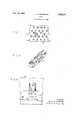
- FIGURE 1is a plan view of the dowel of the present invention in one of its stages of manufacture.
- FIGURE 2is an isometric drawing of the dowel of the instant invention.
- FIGURE 3is a view showing the dowel ofFIGURE 2 securing two members together.
- FIGURE 1is illustrated a blank 14, which may be of any suitable material, prior to its being formed into the generally cylindrical shape of the dowel 12 of FIGURE 2.
- the blank 14 of FIGURE 1has two sets of holding projections 15 and 16 projecting at an angle less than the perpendicular therefrom, which projections may be formed on the blank 14 by any desired means, for example by a stamping proces or the like.
- the blank 14, of FIGURE 1, from which my dowel is formed,is not shaped into true cylindrical form in constructing the dowel of FIGURE 2. I have found that if one or more of the ends 18, 19 of the blank are turned inwardly towards the center of the cylinder, as clearly shown in FIGURE 2, certain characteristics are imparted to the dowel as more fully described hereinafter.
- one end of the dowelis driven into a recess 25 formed in one of the members, for example member 26 of FIGURE 3, to be joined.
- the dowelis driven into such member 26 of the projections 15, because of their inclination in a direction opposite to the direction of travel of the dowel, allow free movement of the dowel, the projections 15 being compressed to the extent necessary, until such time as locator projection 16a engages said member 26 at which time travel of the dowel is terminated.
- the portion of the dowel extending from said first recessis then inserted in a recess formed in the member 27 to be joined to the first member 26 until the two members 26 and 27 abut each other at which time the joint is complete with the holding projections preventing separation of the members 26, 27.
- My dowelovercomes these difficulties by virtue of its unique construction.
- a certain amount of flexibility imparted to the instant dowel due to the manner in which one or more of the ends 18, 19 are bent inwardly towards the center, as well as the flexibility resulting from the spring action of the projections 15 and 16,serves to render the dowel 14 easily adaptable to joining members that do not have holes of a precise uniform diameter.
- the problem incurred where the holes in the various members may be drilled to a non-uniform depthit will be appreciated that I have overcome this problem by forming my dowel with the locating projections 15a and 16a which serve to limit the depth to which the dowel can be inserted in any such hole.
- the inwardly directed end or ends 18, 19impart flexibility to the dowel of the instant invention, yet they also serve a useful purpose in preventing the dowel from collapsing to such an extent that it would be ineffective when the dowel is inserted in an opening in a member to be joined.
- a one-piece dowelcomprising a longitudinally slit tubular shaped, resilient member, said member having a first edge portion along one side of the slit extending at least partially on each side of the transverse centerline of the dowel and projecting substantially radially towards the interior thereof, said first edge portion defining a substantially planar flange for abutting relationship with a second edge portion thereof to block movement, of said secondedge portion and thereby prevent collapse of the tubular member upon its insertion into an opening in a workpiece, said member having two groups of inclined projections projecting from an outer surface thereof, one group of said projections being confined to one longitudinal half of the member and projecting in a direction toward the end of said member remote from said one half, the other group of said projections being confined to the other half of the member and projecting in a direction toward the other end of said member, said projections having penetrating tips for impinging members to be joinedrtogether.
- a one-piece dowelcomprising a longitudinally slit tubular shaped, resilient member, said member having a first edge portion along one side of the slit extending at least partially on each side of the transverse centerline of the dowel and projecting substantially radially towards the interior thereof, said first edge portion defining a substantially planar flange for abutting relationship with a second edge portion and thereby prevent collapse of the tubular member upon its insertion into an opening in a work-piece, said member having two groups of inclined projections projecting from an outer surface thereof, one group of said projections being confined to one longitudinal half of the member and projecting in a direction toward the end of said member remote from said one half, the other group of said projections being confined to the other half of the member and projecting in a direction toward the other end of said member, said projections having penetrating tips for impinging members to be joined together, at least one of said projections having its distal end, located at a point between and equidistant or nearly so from said ends
Landscapes
- Engineering & Computer Science (AREA)
- General Engineering & Computer Science (AREA)
- Mechanical Engineering (AREA)
- Furniture Connections (AREA)
Description
Nov. 14, 1967 A. H. CRAWFORD 3,352,191
DOWEL Filed April 23. 1965 i v FIG.|. $32 \Zn g IMAM A A? .8 z A A M M9 FIG.2.
INVENTOR. ALLAN H. CRAWFORD Uited St tes Fine 3,352,191 DUWEL Alian H. (Irawford, 72 11th Ave, Amsterdam, NX. 12$1ti Fitted Apr. 23, 1965, Set. No. 450,393 2 Claims. ((31. 85-14) The present invention relates to a device useful in the assembly of furniture and more particularly to a dowel which is simple to manufacture and has a number of useful characteristics not heretofore found in the prior art.
A large number of furniture items have doweled joints and in most instances the usual manner of doweling those joints consist of using a wooden dowel having a relatively smooth exterior surface which fits into recesses in each member to be joined and applying an adhesive such as glue or the like to the dowel surface and/or the surfaces of the items to be joined. Although such practice generally provides good holding results at the time of manufacture, it is a well known fact that such joints have a tendency to fail during protracted use due to the ageing of the glue, drying out of the joint when the items of furniture is exposed to a dry atmosphere, or fracture of the dowel itself. Another serious handicap which I have found in connection with using the conventional wooden dowel and adhesive joint is that such a method of joining does not lend itself to efficient assembly line manufacture of furniture items as discussed below.
It will be appreciated by those skilled in the art that, when a glued joint is formed in the furniture manufacturing art, it is generally necessary to allow the glued item to stand for a period of time, generally in a compressed condition, in order that the adhesive be allowed to set. If the latter procedure is not followed, it frequently happens that the joint will loosen and become deformed as subsequent steps are performed in the assembly of the item.
Such a manner of forming joints does not lend itself to present day assembly line construction of furniture or the like and in an effort to overcome the inherent disadvantage of the glued dowel joint, I have provided my improved dowel as described hereinafter.
It is an object of this invention to provide a dowel useful in forming joints which will perform its holding function consistently and lastingly without regard to the various climatic atmospheres to which it may be exposed.
It is a further object of this invention to provide a dowel which, immediately upon its being positioned in place, is capable of performing its ultimate function of forming a secure joint without the necessity of having to set for any period of time prior to becoming fully operative.
It is a still further object of this invention to provide a dowel which is simple in construction, inexpensive to manufacture, and easy to install affording economy in use of materials and which is efiicient in all the functions for which it is designed.
Keeping the above objects in mind, I now proceed to a detailed description of my invention, reference being had to the accompanying drawings forming a part of this application, wherein like reference characters indicate corresponding parts in all views and in which:
FIGURE 1 is a plan view of the dowel of the present invention in one of its stages of manufacture.
FIGURE 2 is an isometric drawing of the dowel of the instant invention.
FIGURE 3 is a view showing the dowel ofFIGURE 2 securing two members together.
In FIGURE 1 is illustrated a blank 14, which may be of any suitable material, prior to its being formed into the generally cylindrical shape of the dowel 12 of FIGURE 2. The blank 14 of FIGURE 1 has two sets ofholding projections
All of theprojections 15 it will be noted lie on one side of thecenterline 17, FIGURE 1, while all of theprojections 16 lie on the opposite side of thecenterline 17, yet each of theprojections
In addition to theprojections 15 and 16 I have provided my dowel with at least two additional locating projections 15a and 16a, each of the latter having its distal end located precisely or nearly so in the plane of thecenterline 17. The latter projections serve a purpose described below.
The blank 14, of FIGURE 1, from which my dowel is formed, is not shaped into true cylindrical form in constructing the dowel of FIGURE 2. I have found that if one or more of theends
When using the dowel 12 to join two members, one end of the dowel, for example the end 21, is driven into arecess 25 formed in one of the members, forexample member 26 of FIGURE 3, to be joined. As the dowel is driven intosuch member 26 of theprojections 15, because of their inclination in a direction opposite to the direction of travel of the dowel, allow free movement of the dowel, theprojections 15 being compressed to the extent necessary, until such time as locator projection 16a engages saidmember 26 at which time travel of the dowel is terminated. The portion of the dowel extending from said first recess is then inserted in a recess formed in themember 27 to be joined to thefirst member 26 until the twomembers members
Those persons skilled in the art to which this invention pertains will appreciate the fact that the holes into which dowels are inserted are not always of uniform width or length and this condition oftentimes results in poorly formed joints when using conventional wooden dowels or the like, in that, in the case of a hole of a diameter greater than the dowel there is a tendency for the dowel to fit loosely, while in the case of a hole not drilled to a predetermined depth, it frequently happens that unequal lengths of dowel will be inserted in the members to be joined such the bearing surface of the dowell against each of the members will be unequal, thereby possibly resulting in a less than satisfactory connection.
My dowel overcomes these difficulties by virtue of its unique construction. A certain amount of flexibility imparted to the instant dowel due to the manner in which one or more of theends projections dowel 14 easily adaptable to joining members that do not have holes of a precise uniform diameter. As for the problem incurred where the holes in the various members may be drilled to a non-uniform depth, it will be appreciated that I have overcome this problem by forming my dowel with the locating projections 15a and 16a which serve to limit the depth to which the dowel can be inserted in any such hole.
As above mentioned, the inwardly directed end orends
Although I have shown and described my dowel as being generally cylindrical in shape, I wish it to be understood that the novel features of construction herein illustrated and described would be equally useful when applied to dowel members of shapes other than that illustrated for example, dowels having a generally rectangular cross sectional area.
Many modifications within the scope of the invention will occur to, those skilled in the art. The invention therefore is not limited to the form illustrated and described.
What is claimed is:
1. A one-piece dowel comprising a longitudinally slit tubular shaped, resilient member, said member having a first edge portion along one side of the slit extending at least partially on each side of the transverse centerline of the dowel and projecting substantially radially towards the interior thereof, said first edge portion defining a substantially planar flange for abutting relationship with a second edge portion thereof to block movement, of said secondedge portion and thereby prevent collapse of the tubular member upon its insertion into an opening in a workpiece, said member having two groups of inclined projections projecting from an outer surface thereof, one group of said projections being confined to one longitudinal half of the member and projecting in a direction toward the end of said member remote from said one half, the other group of said projections being confined to the other half of the member and projecting in a direction toward the other end of said member, said projections having penetrating tips for impinging members to be joinedrtogether.
2. A one-piece dowel comprising a longitudinally slit tubular shaped, resilient member, said member having a first edge portion along one side of the slit extending at least partially on each side of the transverse centerline of the dowel and projecting substantially radially towards the interior thereof, said first edge portion defining a substantially planar flange for abutting relationship with a second edge portion and thereby prevent collapse of the tubular member upon its insertion into an opening in a work-piece, said member having two groups of inclined projections projecting from an outer surface thereof, one group of said projections being confined to one longitudinal half of the member and projecting in a direction toward the end of said member remote from said one half, the other group of said projections being confined to the other half of the member and projecting in a direction toward the other end of said member, said projections having penetrating tips for impinging members to be joined together, at least one of said projections having its distal end, located at a point between and equidistant or nearly so from said ends to define means for locating the dowel in a pairof holes in members to be joined.
References Cited UNITED STATES PATENTS 141,810 8/1873 Nichols 85-11 624,758 I 5/1899 Curtin i 85-11 825,069 7/1906 Peirce 8514 1,354,549 10/1920 Gilmer ,8514 1,993,965 3/1935 Huck et al .a 138-128 2,972,275 2/1961 Baubles 85-83 FOREIGN PATENTS 444,883 5/ 1927 Germany. 974,115 11/ 1964 Great Britain.
CARL W. TOMLIN, Primary Examiner.
R. S. BRITT, Assistant Examiner
Claims (1)
- 2. A ONE-PIECE DOWEL COMPRISING A LONGITUDINALLY SLIT TUBULAR SHAPED, RESILIENT MEMBER, SAID MEMBER HAVING A FIRST EDGE PORTION ALONG ONE SIDE OF THE SLIT EXTENDING AT LEAST PARTIALLY ON EACH SIDE OF THE TRANSVERSE CENTERLINE OF THE DOWEL AND PROJECTING SUBSTANTIALLY RADIALLY TOWARDS THE INTERIOR THEREOF, SAID FIRST EDGE PORTION DEFINGING A SUBSTANTIALLY PLANAR FLANGE FOR ABUTTING RELATIONSHIP WITH A SECOND EDGE PORTION AND THEREBY PREVENT COLLAPSE OF THE TUBULAR MEMBER UPON ITS INSERTION INTO AN OPENING IN A WORKPIECE, SAID MEMBER HAVING TWO GROUPS OF INCLINED PROJECTIONS PROJECTING FROM AN OUTER SURFACE THEREOF, ONE GROUP OF SAID PROJECTIONS BEING CONFINED TO ONE LONGITUDINAL HALF OF THE MEMBER AND PROJECTING IN A DIRECTION TOWARD
Priority Applications (1)
| Application Number | Priority Date | Filing Date | Title |
|---|---|---|---|
| US450393AUS3352191A (en) | 1965-04-23 | 1965-04-23 | Dowel |
Applications Claiming Priority (1)
| Application Number | Priority Date | Filing Date | Title |
|---|---|---|---|
| US450393AUS3352191A (en) | 1965-04-23 | 1965-04-23 | Dowel |
Publications (1)
| Publication Number | Publication Date |
|---|---|
| US3352191Atrue US3352191A (en) | 1967-11-14 |
Family
ID=23787901
Family Applications (1)
| Application Number | Title | Priority Date | Filing Date |
|---|---|---|---|
| US450393AExpired - LifetimeUS3352191A (en) | 1965-04-23 | 1965-04-23 | Dowel |
Country Status (1)
| Country | Link |
|---|---|
| US (1) | US3352191A (en) |
Cited By (61)
| Publication number | Priority date | Publication date | Assignee | Title |
|---|---|---|---|---|
| US3792822A (en)* | 1972-08-21 | 1974-02-19 | M Underhill | Tissue roll holder |
| US3810341A (en)* | 1970-06-12 | 1974-05-14 | H Holz | Multipart joining element for butt and corner joints |
| US3986429A (en)* | 1975-02-24 | 1976-10-19 | Hilti Aktiengesellschaft | Expansion dowell with circumferentially extending protrusions |
| US3990803A (en)* | 1974-05-04 | 1976-11-09 | Paul Fischbach | Fixing sleeves or bushings |
| US4021967A (en)* | 1975-11-10 | 1977-05-10 | Odl, Incorporated | Door light fastener |
| FR2403482A1 (en)* | 1977-09-20 | 1979-04-13 | Bredal Torben | ANCHOR ANCHOR FOR MEDIUM-HARD MATERIALS SUCH AS CHIPBOARDS |
| FR2426778A1 (en)* | 1978-05-22 | 1979-12-21 | Placoplatre Sa | Self-anchoring hanger for suspended ceiling - comprises steel plate with cut and folded flap barbs and is driven into crevice between e.g. floor beams |
| DE3229207A1 (en)* | 1982-08-05 | 1984-04-05 | Wabco Westinghouse Fahrzeugbremsen GmbH, 3000 Hannover | Clamping socket for a rod sensor |
| US4481702A (en)* | 1982-09-30 | 1984-11-13 | The Boeing Company | Method of assembling threaded insert bushing within a working material |
| US4541797A (en)* | 1983-10-26 | 1985-09-17 | Robertshaw Controls Company | Fuel control system having an electrical ignition probe, parts therefor and methods of making the same |
| US4583755A (en)* | 1984-12-04 | 1986-04-22 | Huffy Corporation | Bicycle frame |
| US4814961A (en)* | 1987-12-21 | 1989-03-21 | The Toro Company | Light fixture |
| US5022777A (en)* | 1990-05-23 | 1991-06-11 | Intermetro Industries Corporation | Post connector |
| US5174676A (en)* | 1990-05-23 | 1992-12-29 | Intermetro Industries Corporation | Post connector |
| FR2683274A1 (en)* | 1991-10-31 | 1993-05-07 | Strulik Sa | System for fastening a component |
| EP0604696A1 (en)* | 1992-12-31 | 1994-07-06 | Confast Technologies Limited | Fastener element |
| FR2705124A1 (en)* | 1993-05-10 | 1994-11-18 | Rive Michel | Pin which takes up diametral play |
| US5560731A (en)* | 1993-05-10 | 1996-10-01 | Helmut Lingemann | Plug connector for hollow sections |
| EP0776735A1 (en)* | 1995-11-28 | 1997-06-04 | Jochen Hoene | Sleeve for guiding, deflecting and holding a nail and a method for manufacturing the same |
| WO1998029011A1 (en)* | 1996-12-31 | 1998-07-09 | Gunten Lee L Von | Gravity shelf structure support |
| US5820323A (en)* | 1992-07-30 | 1998-10-13 | Splitfast Technologies Limited | Weld-on fastener, welding equipment for the welding of the fastener, and arrangement for the fastening of an assembly part to the weldable fastener |
| US6241747B1 (en)* | 1993-05-03 | 2001-06-05 | Quill Medical, Inc. | Barbed Bodily tissue connector |
| US6599310B2 (en) | 2001-06-29 | 2003-07-29 | Quill Medical, Inc. | Suture method |
| US6679669B2 (en)* | 2001-06-28 | 2004-01-20 | Illinois Tool Works Inc. | Fastener for wood having locking portion |
| US20040030354A1 (en)* | 2002-08-09 | 2004-02-12 | Leung Jeffrey C. | Suture anchor and method |
| US7056331B2 (en) | 2001-06-29 | 2006-06-06 | Quill Medical, Inc. | Suture method |
| US20060228193A1 (en)* | 2005-04-07 | 2006-10-12 | Michael Apsey | Dowel with locking features and method of using the same |
| DE102005030435A1 (en)* | 2005-06-30 | 2007-01-04 | William Prym Gmbh & Co. Kg | mounting sleeve |
| US7225512B2 (en) | 2001-08-31 | 2007-06-05 | Quill Medical, Inc. | Method of forming barbs on a suture and apparatus for performing same |
| US7624487B2 (en) | 2003-05-13 | 2009-12-01 | Quill Medical, Inc. | Apparatus and method for forming barbs on a suture |
| US20100111594A1 (en)* | 2008-11-05 | 2010-05-06 | Rolls-Royce Plc | Assembly comprising first and second components |
| US20100298871A1 (en)* | 2004-05-14 | 2010-11-25 | Quill Medical, Inc. | Self-retaining wound closure device including an anchoring loop |
| US20110142547A1 (en)* | 2009-12-10 | 2011-06-16 | Willamette Graystone, Inc. | Pier bracket |
| US8118834B1 (en) | 2007-12-20 | 2012-02-21 | Angiotech Pharmaceuticals, Inc. | Composite self-retaining sutures and method |
| US8216273B1 (en) | 2008-02-25 | 2012-07-10 | Ethicon, Inc. | Self-retainers with supporting structures on a suture |
| US20130284995A1 (en)* | 2012-04-30 | 2013-10-31 | Scott Myer | Fence Post Assembly |
| US8615856B1 (en) | 2008-01-30 | 2013-12-31 | Ethicon, Inc. | Apparatus and method for forming self-retaining sutures |
| US8641732B1 (en) | 2008-02-26 | 2014-02-04 | Ethicon, Inc. | Self-retaining suture with variable dimension filament and method |
| US8721681B2 (en) | 2002-09-30 | 2014-05-13 | Ethicon, Inc. | Barbed suture in combination with surgical needle |
| US8734485B2 (en) | 2002-09-30 | 2014-05-27 | Ethicon, Inc. | Sutures with barbs that overlap and cover projections |
| US8771313B2 (en) | 2007-12-19 | 2014-07-08 | Ethicon, Inc. | Self-retaining sutures with heat-contact mediated retainers |
| US8777987B2 (en) | 2007-09-27 | 2014-07-15 | Ethicon, Inc. | Self-retaining sutures including tissue retainers having improved strength |
| US8793863B2 (en) | 2007-04-13 | 2014-08-05 | Ethicon, Inc. | Method and apparatus for forming retainers on a suture |
| US20140222037A1 (en)* | 2013-02-01 | 2014-08-07 | Albara Mohammed BINOTHMAN | Feather imping method |
| US8875607B2 (en) | 2008-01-30 | 2014-11-04 | Ethicon, Inc. | Apparatus and method for forming self-retaining sutures |
| US8876865B2 (en) | 2008-04-15 | 2014-11-04 | Ethicon, Inc. | Self-retaining sutures with bi-directional retainers or uni-directional retainers |
| US8916077B1 (en) | 2007-12-19 | 2014-12-23 | Ethicon, Inc. | Self-retaining sutures with retainers formed from molten material |
| US8932328B2 (en) | 2008-11-03 | 2015-01-13 | Ethicon, Inc. | Length of self-retaining suture and method and device for using the same |
| US8961560B2 (en) | 2008-05-16 | 2015-02-24 | Ethicon, Inc. | Bidirectional self-retaining sutures with laser-marked and/or non-laser marked indicia and methods |
| USRE45426E1 (en) | 1997-05-21 | 2015-03-17 | Ethicon, Inc. | Surgical methods using one-way suture |
| US20150135879A1 (en)* | 2013-11-15 | 2015-05-21 | Hyundai Motor Company | Structure for mounting plantable shift lever onto bracket |
| US20150211558A1 (en)* | 2014-01-29 | 2015-07-30 | Covidien Lp | Devices and methods for securing component pieces |
| US9125647B2 (en) | 2008-02-21 | 2015-09-08 | Ethicon, Inc. | Method and apparatus for elevating retainers on self-retaining sutures |
| US9248580B2 (en) | 2002-09-30 | 2016-02-02 | Ethicon, Inc. | Barb configurations for barbed sutures |
| US9675341B2 (en) | 2010-11-09 | 2017-06-13 | Ethicon Inc. | Emergency self-retaining sutures and packaging |
| US9955962B2 (en) | 2010-06-11 | 2018-05-01 | Ethicon, Inc. | Suture delivery tools for endoscopic and robot-assisted surgery and methods |
| US20180119413A1 (en)* | 2016-10-31 | 2018-05-03 | Jin-Jie Lin | Concealed Post Tie |
| US10188384B2 (en) | 2011-06-06 | 2019-01-29 | Ethicon, Inc. | Methods and devices for soft palate tissue elevation procedures |
| US10420546B2 (en) | 2010-05-04 | 2019-09-24 | Ethicon, Inc. | Self-retaining systems having laser-cut retainers |
| US10492780B2 (en) | 2011-03-23 | 2019-12-03 | Ethicon, Inc. | Self-retaining variable loop sutures |
| US11007296B2 (en) | 2010-11-03 | 2021-05-18 | Ethicon, Inc. | Drug-eluting self-retaining sutures and methods relating thereto |
Citations (8)
| Publication number | Priority date | Publication date | Assignee | Title |
|---|---|---|---|---|
| US141810A (en)* | 1873-08-12 | Improvement in nails | ||
| US674758A (en)* | 1900-11-12 | 1901-05-21 | Rebecca J Cole | Kitchen-cabinet. |
| US825069A (en)* | 1905-02-27 | 1906-07-03 | Ralph S Peirce | Dowel-pin for electrical conduits. |
| US1354549A (en)* | 1919-04-16 | 1920-10-05 | John T Gilmer | Dowel-pin |
| DE444883C (en)* | 1924-07-23 | 1927-05-27 | Hans Hoffmann | Dowel pin for locating two machine parts |
| US1993965A (en)* | 1930-02-03 | 1935-03-12 | Chicago Tubing And Braiding Co | Tubing |
| US2972275A (en)* | 1958-02-27 | 1961-02-21 | Elastic Stop Nut Corp | Resilient split pin with inwardly extending portion |
| GB974115A (en)* | 1961-12-15 | 1964-11-04 | Carr Fastener Co Ltd | Device for connecting tubes or tube-like elements to one another |
- 1965
- 1965-04-23USUS450393Apatent/US3352191A/ennot_activeExpired - Lifetime
Patent Citations (8)
| Publication number | Priority date | Publication date | Assignee | Title |
|---|---|---|---|---|
| US141810A (en)* | 1873-08-12 | Improvement in nails | ||
| US674758A (en)* | 1900-11-12 | 1901-05-21 | Rebecca J Cole | Kitchen-cabinet. |
| US825069A (en)* | 1905-02-27 | 1906-07-03 | Ralph S Peirce | Dowel-pin for electrical conduits. |
| US1354549A (en)* | 1919-04-16 | 1920-10-05 | John T Gilmer | Dowel-pin |
| DE444883C (en)* | 1924-07-23 | 1927-05-27 | Hans Hoffmann | Dowel pin for locating two machine parts |
| US1993965A (en)* | 1930-02-03 | 1935-03-12 | Chicago Tubing And Braiding Co | Tubing |
| US2972275A (en)* | 1958-02-27 | 1961-02-21 | Elastic Stop Nut Corp | Resilient split pin with inwardly extending portion |
| GB974115A (en)* | 1961-12-15 | 1964-11-04 | Carr Fastener Co Ltd | Device for connecting tubes or tube-like elements to one another |
Cited By (114)
| Publication number | Priority date | Publication date | Assignee | Title |
|---|---|---|---|---|
| US3810341A (en)* | 1970-06-12 | 1974-05-14 | H Holz | Multipart joining element for butt and corner joints |
| US3792822A (en)* | 1972-08-21 | 1974-02-19 | M Underhill | Tissue roll holder |
| US3990803A (en)* | 1974-05-04 | 1976-11-09 | Paul Fischbach | Fixing sleeves or bushings |
| US3986429A (en)* | 1975-02-24 | 1976-10-19 | Hilti Aktiengesellschaft | Expansion dowell with circumferentially extending protrusions |
| US4021967A (en)* | 1975-11-10 | 1977-05-10 | Odl, Incorporated | Door light fastener |
| FR2403482A1 (en)* | 1977-09-20 | 1979-04-13 | Bredal Torben | ANCHOR ANCHOR FOR MEDIUM-HARD MATERIALS SUCH AS CHIPBOARDS |
| FR2426778A1 (en)* | 1978-05-22 | 1979-12-21 | Placoplatre Sa | Self-anchoring hanger for suspended ceiling - comprises steel plate with cut and folded flap barbs and is driven into crevice between e.g. floor beams |
| DE3229207A1 (en)* | 1982-08-05 | 1984-04-05 | Wabco Westinghouse Fahrzeugbremsen GmbH, 3000 Hannover | Clamping socket for a rod sensor |
| US4481702A (en)* | 1982-09-30 | 1984-11-13 | The Boeing Company | Method of assembling threaded insert bushing within a working material |
| US4541797A (en)* | 1983-10-26 | 1985-09-17 | Robertshaw Controls Company | Fuel control system having an electrical ignition probe, parts therefor and methods of making the same |
| US4583755A (en)* | 1984-12-04 | 1986-04-22 | Huffy Corporation | Bicycle frame |
| US4814961A (en)* | 1987-12-21 | 1989-03-21 | The Toro Company | Light fixture |
| US5022777A (en)* | 1990-05-23 | 1991-06-11 | Intermetro Industries Corporation | Post connector |
| US5174676A (en)* | 1990-05-23 | 1992-12-29 | Intermetro Industries Corporation | Post connector |
| FR2683274A1 (en)* | 1991-10-31 | 1993-05-07 | Strulik Sa | System for fastening a component |
| US6186391B1 (en) | 1992-07-30 | 2001-02-13 | Splitfast Technologies Limited | Welding assembly apparatus for welding fasteners to a component and method of welding fasteners to the component |
| US5820323A (en)* | 1992-07-30 | 1998-10-13 | Splitfast Technologies Limited | Weld-on fastener, welding equipment for the welding of the fastener, and arrangement for the fastening of an assembly part to the weldable fastener |
| EP0604696A1 (en)* | 1992-12-31 | 1994-07-06 | Confast Technologies Limited | Fastener element |
| US7806908B2 (en) | 1993-05-03 | 2010-10-05 | Quill Medical, Inc. | Barbed tissue connector |
| US6241747B1 (en)* | 1993-05-03 | 2001-06-05 | Quill Medical, Inc. | Barbed Bodily tissue connector |
| US20070208355A1 (en)* | 1993-05-03 | 2007-09-06 | Ruff Gregory L | Barbed tissue connector |
| US20080221617A1 (en)* | 1993-05-03 | 2008-09-11 | Quill Medical, Inc. | Barbed tissue connector |
| US20040093028A1 (en)* | 1993-05-03 | 2004-05-13 | Ruff Gregory L. | Barbed bodily tissue connector |
| US8246652B2 (en) | 1993-05-03 | 2012-08-21 | Ethicon, Inc. | Suture with a pointed end and an anchor end and with equally spaced yieldable tissue grasping barbs located at successive axial locations |
| US7226468B2 (en) | 1993-05-03 | 2007-06-05 | Quill Medical, Inc. | Barbed bodily tissue connector |
| FR2705124A1 (en)* | 1993-05-10 | 1994-11-18 | Rive Michel | Pin which takes up diametral play |
| US5560731A (en)* | 1993-05-10 | 1996-10-01 | Helmut Lingemann | Plug connector for hollow sections |
| EP0776735A1 (en)* | 1995-11-28 | 1997-06-04 | Jochen Hoene | Sleeve for guiding, deflecting and holding a nail and a method for manufacturing the same |
| GB2335475B (en)* | 1996-12-31 | 2001-01-17 | Gunten Lee Louis Von | Gravity shelf structure support |
| WO1998029011A1 (en)* | 1996-12-31 | 1998-07-09 | Gunten Lee L Von | Gravity shelf structure support |
| GB2335475A (en)* | 1996-12-31 | 1999-09-22 | Gunten Lee Louis Von | Gravity shelf structure support |
| US5797501A (en)* | 1996-12-31 | 1998-08-25 | Gunten Lee L Von | Gravity shelf structure support |
| USRE45426E1 (en) | 1997-05-21 | 2015-03-17 | Ethicon, Inc. | Surgical methods using one-way suture |
| US6679669B2 (en)* | 2001-06-28 | 2004-01-20 | Illinois Tool Works Inc. | Fastener for wood having locking portion |
| US8747437B2 (en) | 2001-06-29 | 2014-06-10 | Ethicon, Inc. | Continuous stitch wound closure utilizing one-way suture |
| US6599310B2 (en) | 2001-06-29 | 2003-07-29 | Quill Medical, Inc. | Suture method |
| US8777989B2 (en) | 2001-06-29 | 2014-07-15 | Ethicon, Inc. | Subcutaneous sinusoidal wound closure utilizing one-way suture |
| US20070208377A1 (en)* | 2001-06-29 | 2007-09-06 | Andrew Kaplan | Suture Method |
| US8777988B2 (en) | 2001-06-29 | 2014-07-15 | Ethicon, Inc. | Methods for using self-retaining sutures in endoscopic procedures |
| US7056331B2 (en) | 2001-06-29 | 2006-06-06 | Quill Medical, Inc. | Suture method |
| US8764776B2 (en) | 2001-06-29 | 2014-07-01 | Ethicon, Inc. | Anastomosis method using self-retaining sutures |
| US8764796B2 (en) | 2001-06-29 | 2014-07-01 | Ethicon, Inc. | Suture method |
| US7857829B2 (en) | 2001-06-29 | 2010-12-28 | Quill Medical, Inc. | Suture method |
| US7913365B2 (en) | 2001-08-31 | 2011-03-29 | Quill Medical, Inc. | Method of forming barbs on a suture and apparatus for performing same |
| US8028387B2 (en) | 2001-08-31 | 2011-10-04 | Quill Medical, Inc. | System for supporting and cutting suture thread to create tissue retainers thereon |
| US8926659B2 (en) | 2001-08-31 | 2015-01-06 | Ethicon, Inc. | Barbed suture created having barbs defined by variable-angle cut |
| US7225512B2 (en) | 2001-08-31 | 2007-06-05 | Quill Medical, Inc. | Method of forming barbs on a suture and apparatus for performing same |
| US7996967B2 (en) | 2001-08-31 | 2011-08-16 | Quill Medical, Inc. | System for variable-angle cutting of a suture to create tissue retainers of a desired shape and size |
| US7996968B2 (en) | 2001-08-31 | 2011-08-16 | Quill Medical, Inc. | Automated method for cutting tissue retainers on a suture |
| US8011072B2 (en) | 2001-08-31 | 2011-09-06 | Quill Medical, Inc. | Method for variable-angle cutting of a suture to create tissue retainers of a desired shape and size |
| US8015678B2 (en) | 2001-08-31 | 2011-09-13 | Quill Medical, Inc. | Method for cutting a suture to create tissue retainers of a desired shape and size |
| US8020263B2 (en) | 2001-08-31 | 2011-09-20 | Quill Medical, Inc. | Automated system for cutting tissue retainers on a suture |
| US20070187861A1 (en)* | 2001-08-31 | 2007-08-16 | Quill Medical, Inc. | Method of Forming Barbs on a Suture and Apparatus for Performing Same |
| US8028388B2 (en) | 2001-08-31 | 2011-10-04 | Quill Medical, Inc. | System for cutting a suture to create tissue retainers of a desired shape and size |
| US8690914B2 (en) | 2002-08-09 | 2014-04-08 | Ethicon, Inc. | Suture with an intermediate barbed body |
| US8083770B2 (en) | 2002-08-09 | 2011-12-27 | Quill Medical, Inc. | Suture anchor and method |
| US20040030354A1 (en)* | 2002-08-09 | 2004-02-12 | Leung Jeffrey C. | Suture anchor and method |
| US8679158B2 (en) | 2002-08-09 | 2014-03-25 | Ethicon, Inc. | Multiple suture thread configuration with an intermediate connector |
| US8652170B2 (en) | 2002-08-09 | 2014-02-18 | Ethicon, Inc. | Double ended barbed suture with an intermediate body |
| US8734486B2 (en) | 2002-08-09 | 2014-05-27 | Ethicon, Inc. | Multiple suture thread configuration with an intermediate connector |
| US8734485B2 (en) | 2002-09-30 | 2014-05-27 | Ethicon, Inc. | Sutures with barbs that overlap and cover projections |
| US8721681B2 (en) | 2002-09-30 | 2014-05-13 | Ethicon, Inc. | Barbed suture in combination with surgical needle |
| US9248580B2 (en) | 2002-09-30 | 2016-02-02 | Ethicon, Inc. | Barb configurations for barbed sutures |
| US8821540B2 (en) | 2002-09-30 | 2014-09-02 | Ethicon, Inc. | Self-retaining sutures having effective holding strength and tensile strength |
| US8795332B2 (en) | 2002-09-30 | 2014-08-05 | Ethicon, Inc. | Barbed sutures |
| US8852232B2 (en) | 2002-09-30 | 2014-10-07 | Ethicon, Inc. | Self-retaining sutures having effective holding strength and tensile strength |
| US7624487B2 (en) | 2003-05-13 | 2009-12-01 | Quill Medical, Inc. | Apparatus and method for forming barbs on a suture |
| US8032996B2 (en) | 2003-05-13 | 2011-10-11 | Quill Medical, Inc. | Apparatus for forming barbs on a suture |
| US20100298871A1 (en)* | 2004-05-14 | 2010-11-25 | Quill Medical, Inc. | Self-retaining wound closure device including an anchoring loop |
| US10548592B2 (en) | 2004-05-14 | 2020-02-04 | Ethicon, Inc. | Suture methods and devices |
| US10779815B2 (en) | 2004-05-14 | 2020-09-22 | Ethicon, Inc. | Suture methods and devices |
| US8721664B2 (en) | 2004-05-14 | 2014-05-13 | Ethicon, Inc. | Suture methods and devices |
| US11723654B2 (en) | 2004-05-14 | 2023-08-15 | Ethicon, Inc. | Suture methods and devices |
| US20060228193A1 (en)* | 2005-04-07 | 2006-10-12 | Michael Apsey | Dowel with locking features and method of using the same |
| US7241095B2 (en)* | 2005-04-07 | 2007-07-10 | Driv-Lok, Inc. | Dowel with locking features and method of using the same |
| DE102005030435A1 (en)* | 2005-06-30 | 2007-01-04 | William Prym Gmbh & Co. Kg | mounting sleeve |
| US8793863B2 (en) | 2007-04-13 | 2014-08-05 | Ethicon, Inc. | Method and apparatus for forming retainers on a suture |
| US8915943B2 (en) | 2007-04-13 | 2014-12-23 | Ethicon, Inc. | Self-retaining systems for surgical procedures |
| US8777987B2 (en) | 2007-09-27 | 2014-07-15 | Ethicon, Inc. | Self-retaining sutures including tissue retainers having improved strength |
| US9498893B2 (en) | 2007-09-27 | 2016-11-22 | Ethicon, Inc. | Self-retaining sutures including tissue retainers having improved strength |
| US8771313B2 (en) | 2007-12-19 | 2014-07-08 | Ethicon, Inc. | Self-retaining sutures with heat-contact mediated retainers |
| US8916077B1 (en) | 2007-12-19 | 2014-12-23 | Ethicon, Inc. | Self-retaining sutures with retainers formed from molten material |
| US8118834B1 (en) | 2007-12-20 | 2012-02-21 | Angiotech Pharmaceuticals, Inc. | Composite self-retaining sutures and method |
| US9044225B1 (en) | 2007-12-20 | 2015-06-02 | Ethicon, Inc. | Composite self-retaining sutures and method |
| US8875607B2 (en) | 2008-01-30 | 2014-11-04 | Ethicon, Inc. | Apparatus and method for forming self-retaining sutures |
| US8615856B1 (en) | 2008-01-30 | 2013-12-31 | Ethicon, Inc. | Apparatus and method for forming self-retaining sutures |
| US9125647B2 (en) | 2008-02-21 | 2015-09-08 | Ethicon, Inc. | Method and apparatus for elevating retainers on self-retaining sutures |
| US8216273B1 (en) | 2008-02-25 | 2012-07-10 | Ethicon, Inc. | Self-retainers with supporting structures on a suture |
| US8641732B1 (en) | 2008-02-26 | 2014-02-04 | Ethicon, Inc. | Self-retaining suture with variable dimension filament and method |
| US8876865B2 (en) | 2008-04-15 | 2014-11-04 | Ethicon, Inc. | Self-retaining sutures with bi-directional retainers or uni-directional retainers |
| US8961560B2 (en) | 2008-05-16 | 2015-02-24 | Ethicon, Inc. | Bidirectional self-retaining sutures with laser-marked and/or non-laser marked indicia and methods |
| US10441270B2 (en) | 2008-11-03 | 2019-10-15 | Ethicon, Inc. | Length of self-retaining suture and method and device for using the same |
| US11234689B2 (en) | 2008-11-03 | 2022-02-01 | Ethicon, Inc. | Length of self-retaining suture and method and device for using the same |
| US8932328B2 (en) | 2008-11-03 | 2015-01-13 | Ethicon, Inc. | Length of self-retaining suture and method and device for using the same |
| US20100111594A1 (en)* | 2008-11-05 | 2010-05-06 | Rolls-Royce Plc | Assembly comprising first and second components |
| US8602675B2 (en)* | 2008-11-05 | 2013-12-10 | Rolls-Royce Plc | Assembly comprising first and second components |
| US8231309B2 (en) | 2009-12-10 | 2012-07-31 | Willamette Graystone, Inc. | Pier bracket |
| US20110142547A1 (en)* | 2009-12-10 | 2011-06-16 | Willamette Graystone, Inc. | Pier bracket |
| US11234692B2 (en) | 2010-05-04 | 2022-02-01 | Cilag Gmbh International | Self-retaining system having laser-cut retainers |
| US10420546B2 (en) | 2010-05-04 | 2019-09-24 | Ethicon, Inc. | Self-retaining systems having laser-cut retainers |
| US10952721B2 (en) | 2010-05-04 | 2021-03-23 | Ethicon, Inc. | Laser cutting system and methods for creating self-retaining sutures |
| US9955962B2 (en) | 2010-06-11 | 2018-05-01 | Ethicon, Inc. | Suture delivery tools for endoscopic and robot-assisted surgery and methods |
| US11007296B2 (en) | 2010-11-03 | 2021-05-18 | Ethicon, Inc. | Drug-eluting self-retaining sutures and methods relating thereto |
| US9675341B2 (en) | 2010-11-09 | 2017-06-13 | Ethicon Inc. | Emergency self-retaining sutures and packaging |
| US11690614B2 (en) | 2011-03-23 | 2023-07-04 | Ethicon, Inc. | Self-retaining variable loop sutures |
| US10492780B2 (en) | 2011-03-23 | 2019-12-03 | Ethicon, Inc. | Self-retaining variable loop sutures |
| US10188384B2 (en) | 2011-06-06 | 2019-01-29 | Ethicon, Inc. | Methods and devices for soft palate tissue elevation procedures |
| US20130284995A1 (en)* | 2012-04-30 | 2013-10-31 | Scott Myer | Fence Post Assembly |
| US20140222037A1 (en)* | 2013-02-01 | 2014-08-07 | Albara Mohammed BINOTHMAN | Feather imping method |
| US8845226B2 (en)* | 2013-02-01 | 2014-09-30 | Albara Mohammed BINOTHMAN | Feather imping pin |
| US9414900B2 (en)* | 2013-02-01 | 2016-08-16 | Albara Mohammed BINOTHMAN | Feather imping method |
| US20150135879A1 (en)* | 2013-11-15 | 2015-05-21 | Hyundai Motor Company | Structure for mounting plantable shift lever onto bracket |
| US20150211558A1 (en)* | 2014-01-29 | 2015-07-30 | Covidien Lp | Devices and methods for securing component pieces |
| US20180119413A1 (en)* | 2016-10-31 | 2018-05-03 | Jin-Jie Lin | Concealed Post Tie |
Similar Documents
| Publication | Publication Date | Title |
|---|---|---|
| US3352191A (en) | Dowel | |
| US2941439A (en) | Rivet and integral expander pin connected thereto by area of limited cross section | |
| US3443783A (en) | Plastic fastener | |
| US3143915A (en) | Anchor bolts | |
| US1979686A (en) | Metal socket, bush, ferrule, rivet, and the like | |
| US3449799A (en) | Fastener for connecting apertured structure to another structure | |
| CA1200070A (en) | Dowel fastener and joints including same | |
| US6991397B2 (en) | Dowel fastener and joints including same | |
| US2950937A (en) | Fastening device | |
| US2560961A (en) | Fastener | |
| US5658086A (en) | Furniture connector | |
| US2559281A (en) | Anchoring socket for bolts | |
| US4077300A (en) | Plastic screw grommet | |
| KR900006086A (en) | Push-In Fasteners | |
| US2240425A (en) | Fastener | |
| JPH04504608A (en) | plug | |
| US2964989A (en) | Expanding screw anchor | |
| US3437004A (en) | Sheet metal expandable fastener | |
| US2640618A (en) | Blind riveted joint | |
| US3954345A (en) | Self-locking dowell pin | |
| US2396501A (en) | Wall plug | |
| US3741594A (en) | Fastener assembly | |
| US2100873A (en) | Dowel structure | |
| US3318183A (en) | Expansion anchor | |
| US2594211A (en) | Fastener having clamping head |