US3342267A - Turbo-generator heater for oil and gas wells and pipe lines - Google Patents
Turbo-generator heater for oil and gas wells and pipe linesDownload PDFInfo
- Publication number
- US3342267A US3342267AUS451747AUS45174765AUS3342267AUS 3342267 AUS3342267 AUS 3342267AUS 451747 AUS451747 AUS 451747AUS 45174765 AUS45174765 AUS 45174765AUS 3342267 AUS3342267 AUS 3342267A
- Authority
- US
- United States
- Prior art keywords
- tubing
- heating element
- oil
- heating
- tubing string
- Prior art date
- Legal status (The legal status is an assumption and is not a legal conclusion. Google has not performed a legal analysis and makes no representation as to the accuracy of the status listed.)
- Expired - Lifetime
Links
- 238000010438heat treatmentMethods0.000claimsdescription66
- 239000012530fluidSubstances0.000claimsdescription35
- 238000004519manufacturing processMethods0.000claimsdescription28
- 239000003129oil wellSubstances0.000claimsdescription10
- 238000005485electric heatingMethods0.000claimsdescription6
- RLQJEEJISHYWON-UHFFFAOYSA-NflonicamidChemical compoundFC(F)(F)C1=CC=NC=C1C(=O)NCC#NRLQJEEJISHYWON-UHFFFAOYSA-N0.000claims1
- 238000009434installationMethods0.000description17
- 210000004027cellAnatomy0.000description6
- 238000010276constructionMethods0.000description6
- 230000015572biosynthetic processEffects0.000description3
- 230000004048modificationEffects0.000description3
- 238000012986modificationMethods0.000description3
- 210000000352storage cellAnatomy0.000description3
- 241000239290AraneaeSpecies0.000description2
- 239000012188paraffin waxSubstances0.000description2
- 238000005192partitionMethods0.000description2
- 230000009286beneficial effectEffects0.000description1
- 238000007596consolidation processMethods0.000description1
- 230000000694effectsEffects0.000description1
- 230000003028elevating effectEffects0.000description1
- 230000008014freezingEffects0.000description1
- 238000007710freezingMethods0.000description1
- 239000000446fuelSubstances0.000description1
- 238000002955isolationMethods0.000description1
- 239000003208petroleumSubstances0.000description1
- 230000001681protective effectEffects0.000description1
- 230000008439repair processEffects0.000description1
- 238000007789sealingMethods0.000description1
- WKQCYNCZDDJXEK-UHFFFAOYSA-Nsimalikalactone CNatural productsC1C(C23C)OC(=O)CC3C(C)C(=O)C(O)C2C2(C)C1C(C)C=C(OC)C2=OWKQCYNCZDDJXEK-UHFFFAOYSA-N0.000description1
- 238000007669thermal treatmentMethods0.000description1
- XLYOFNOQVPJJNP-UHFFFAOYSA-NwaterSubstancesOXLYOFNOQVPJJNP-UHFFFAOYSA-N0.000description1
- 238000003466weldingMethods0.000description1
Images

Classifications
- E—FIXED CONSTRUCTIONS
- E21—EARTH OR ROCK DRILLING; MINING
- E21B—EARTH OR ROCK DRILLING; OBTAINING OIL, GAS, WATER, SOLUBLE OR MELTABLE MATERIALS OR A SLURRY OF MINERALS FROM WELLS
- E21B36/00—Heating, cooling or insulating arrangements for boreholes or wells, e.g. for use in permafrost zones
- E21B36/04—Heating, cooling or insulating arrangements for boreholes or wells, e.g. for use in permafrost zones using electrical heaters
- E—FIXED CONSTRUCTIONS
- E21—EARTH OR ROCK DRILLING; MINING
- E21B—EARTH OR ROCK DRILLING; OBTAINING OIL, GAS, WATER, SOLUBLE OR MELTABLE MATERIALS OR A SLURRY OF MINERALS FROM WELLS
- E21B41/00—Equipment or details not covered by groups E21B15/00 - E21B40/00
- E21B41/0085—Adaptations of electric power generating means for use in boreholes
Definitions
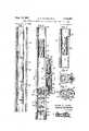
- TURBO-GENERATOR HEATERFOR OIL AND GAS WELLS AND PIPE LINES 2 Sheets-Sheet 3 Filed April 29, 1965 United States Patent O ABSTRACT F THE DISCLSURE
- This inventioncomprises a novel and useful turbogenerator heater for oil and gas wells and pipe lines and more specifically relates to a device associated with the production tubing string of oil wells for applying heat thereto for various beneficial purposes.
- a further object of the inventionto provide a device in accordance with the preceding object which shall be incorporated into the tubing string or pipe line to form a part thereof thereby facilitating locating of the device at any predetermined region in a well bore which requires thermal treatment.
- a still further object of the inventionis to provide a means in accordance with the foregoing objects whereby the heating unit may be so associated with the tubing string that it may form a part thereof and be manipulated thereby in a well bore and yet will offer a minimum obstruction to flow through the tubing string itself.
- a still further important object of the inventionis to provide a device in accordance with the preceding object wherein the means for generating the heat may be disposed entirely in the well bore and preferably within or upon the tubing string so as to be completely independent from the source of energy at the sur-face of the well bore.
- a further and more specic object of the inventionis to provide a device in compliance with the foregoing objects which shall include an electric generator which is energized by a turbine subject to and operated by the flow of well fluid in the tubing string or flow of uid in a pipe line and which generator shall supply electrical energy to heating coils disposed in intimate heat exchange relation with the tubing string.
- a still further and more specific object of the inventionis to provide an installation in accordance with the preceding objects therein the electrical heating coils are incorporated into a tubing string or pipe line and may be energized by electric storage cells likewise incorporated into a tubing string.
- a further and more general object of the inventionis to provide a heating means adapted to be associated generally with pipe lines for the purpose of heating the fluid fiowing therethrough and adapted to be energized by a turbine in turn operated by the fiuid flowing through the pipe line or from any other source of electrical energy.
- FIGURE lis a view in Vertical central section through a portion of a well bore showing therein a tubing string having the turbo-generator heater of this invention incorporated therein;
- FIGURE 2is an enlarged detail view taken in vertical transverse section substantially upon a plane indicated by section line 2 2 of FIGURE l and showing a preferred installation of the heating means in accordance with this invention
- FIGURE 3is a further detail View taken upon an enlarged scale in vertical transverse section substantially upon the plane indicated by section line 3 3 of FIG- URE 1 and showing in particular the heating coil arrangement of the invention.
- FIGURES 4 and 5are horizontal sectional views taken substantially upon the plane indicated by section lines 4 4 and 5 5 respectively of FIGURE 2;
- FIGURE 6is a view similar to FIGURE 2 but showing a modified construction in which the generator unit is housed Within the tubing string;
- FIGURE 7is a detail view in horizontal section taken substantially upon a plane indicated by section line 7 7 of FIGURE 6;
- FIGURE 8is a fragmentary view in vertically longitudinal section showing a still further modification in which the heating coils are powered by electric storage battery means.
- FIGURES 1-5exemplifies a preferred installation adapted for a producing oil well. It is to be emphasized however, that a well tubing is merely one particular form of pipe line to which this invention is applicable and that the showing and description of the invention to a vwell tubing as set forth hereinafter is not to be construed as limiting the invention thereto.
- FIGURES l-7disclose an electrical heater element in good heat exchange relation with a tubing string or pipe line and energized by an electrical generator which in turn is driven by a fluid turbine subjected to the flow of fluid through the tubing string or pipe line.
- the generatoris shown mounted upon but exteriorly of the tubing string or pipe line
- FIGURES 6 and 7it is shown as housed therein.
- the electric heating element and the source of electrical energyare both shown as housed within the tubing string or pipe line with the heating source consisting of electric storage batteries or cells. All forms of the invention are characterized by the close proximity of the source of electrical energy to the heating element and the location of the energy source remote from the surface of the well bore containing the production tubing or the end of a pipe line upon which the installation is mounted.
- FIGURES 1-5J o Embodment of FIGURES 1-5
- the embodiment of FIGURES 1-5is illustrated as a heating installation incorporated into a production tubing string within an oil well bore. It will be appreciated, however, that the installation is equally applicable to any pipe line through which a uid ows which is to be heated and is not limited to the illustrated environment of location within a well bore.
- a conventional cased well borein which is positioned a production tubing string 12 by means of which oil produced by the well bore is brought to the surface of the ground.
- the inventionis equally applicable to production tubing strings of wells which flow under their own formation pressure or to wells in which an artificial ow producing means is required.
- the energy of the fluid flowing through the production tubing stringis utilized as a source of power to generate electrical energy for effecting the heating operation which is the primary purpose of this invention.
- the tubing strin-g 12includes a tubing section 14 or if desired a plurality of detachably connected tubing sections, and which support and carry the various components of this heating installation.
- an electrical generating meansindicated generally by the numeral 20 and which is operatively connected to a power source indicated generally by the numeral 22 and which preferably comprises a uid turbine of the axial ow type together with heating elements each indicated generally by the numeral 24 which as illustrated consists of a pair of electrical resistance heating coils disposed at spaced locations within the tubing section or sections.
- a single coilmay be provided if it is desired to heat only one location within the tubing string or a plurality of such coils or heating elements may be Iutilized when it is desired to provide a more extensive heating region or a plurality of separate heated regions within the tubing string.
- the heating elements 24are usually preferable to ⁇ dispose the heating elements 24 within the tubing string in the interest of compactness, protection of the heating element and to facilitate their installation in a well bore.
- the heating elementsmay be disposed upon the exterior thereof in suitably protective housings and coverings.
- any suitable type of turbine 22may be utilized for the purpose of this invention.
- an axial flow type of turbinewill ⁇ usually be satisfactory of the multiple stage construction.
- a plurality of axially spaced turbine rotors 26are mounted upon a suitable .turbine shaft or shaft sections 28 which in turn is journalled in suitable bearing means 30 within the tubing section or sections.
- the rotor cylindermay be detachably secured within the tubing sections as by means of removable fasteners 32 engaging the bearing members 3d.
- the turbineis so disposed as to offer a minimum obstruction to flow through the tubing sections so as the uid flows upwardly therethrough either under a formation pressure or under some artificial ow producing means, it will through its energy of flow operate the turbine rotors and thus impart rotation to the tunbine shaft 28.
- the turbine shaftin turn is mechanically connected to the electric generator unit 20 as for example by the gearing assembly shown in FIGURE 5.
- the tubing section or sections 14have an opening 34 in one wall thereof and a mounting bracket 36 is disposed adjacent this opening.
- An enclosing housing as at 38which may be removably secured and sealed to the tubing string, or may be permanently united thereto as by welding at 40.
- a ⁇ driving gear 42 fixed to the turbine shaft 28engages an idler gear 44 suitably journalled upon an axle 46 mounted in the bracket 36 and a further mounting bracket 48, this idler gear in turn engaging a drive driven gear 50 fixed to a generator driving shaft 52.
- suitable bearing meanss-uch as those as indicated at 54 which rotatably journal the generator armatures 56.
- the generatorsare preferably of an axially elongated type and one or more units ymay be disposed in axial alignment in order to give the requisite electrical capacity while maintaining the cross-sectional area at a minimum.
- the generatorsin turn are connected electrically as by conduits 56 and 58 to the heating element 24 disposed adjacent thereto.
- this installationoers the advantage that the heating source for the electrical heating element is disposed closely adjacent to the latter, that the heating element and the related heating source are all mounted upon and carried by the tubing string so that they will be readily manipulated into position in the well bore by appropriately positioning the tubing string therein and by properly installing and locating the heating installation during the makeup of the tubing string.
- a further advantage inherent in this constructionis that the usual necessary electric cables to the surface or other means for -supplying electrical energy to the heating elements and for controlling the application of such energy with the mechanical disadvantage attending such installations when the heating element is located in a deep well 'bore isrcompletely overcome.
- the installation describedcan be readily controlled as by throttling the ow or velocity of ow in the tubing string thereby controlling the operation of the turbine.
- control meansare to be applied to the generator itself for effecting the electrical energy applied to the heating elements and thus the heat output of the heating elements.
- FIGURES 6 and 7In the embodiment of FIGURES 1-5, the generator assembly of the installation was shown mounted upon the exterior of the tubing string. This is particularly advantageous when relatively small diameter tubings are utilized and there is insuicient cross-sectional -area within the tubing string for the desired flow of fluid and for housing the generator unit. However, where the internal diameter of the tubing string is not a limiting factor, it will generally be found preferable to house the generator unit within the tubing string since this will eliminate obstructions and projections from the exterior of the tubing string thereby facilitating its manipulation within a w-ell bore or in other environments. Such an arrangement is illustrated in the embodiments of FIGURES 6 and 7.
- tubing string 12is shown having tubing section or sections 14 in which is housed the components of the installation including the heating element or elements 24, the turbine assembly 22 and the generator unit or assembly 20.
- heating element 24is illustrated although it will be understood that any desired number of heating elements may be provided as in the preceding embodiment.
- the interior of the tubing string section or sections 14are provided with axially spaced supporting rings or spiders 70 and 72 each of which has a pair of transversely extending bearing supports 74 and 76.
- the supports 74 and 76 of the two spidersserve to rotatably journal the generating unit drive shaft 7S and the turbine driving shaft 80.
- the two shaftsoperatively connected together as by driving gears 82 on the turbine shaft engaging driven gears 84 upon the generator drive shafts.
- an enclosing housing 86having transversely extending partition plates as at 8S and 90 which extend entirely thereacross and thus isolate and seal a chamber 92 which contains the armature and coils of the generator 'unit 20 in a fluid tight sealed manner.
- ySuitable bearings as at 94 and 96 and a sealing means as at 91")lare provided in these partitions to rotatably journal the generator armature and to establish a fluid tight seal and isolation of the chamber 92.
- the turbineis disposed within the flowing fluid of the tubing string for operation thereby and in turn serves as a source of power to drive the. generator 20, which latter is connected electrically as bythe conduit means 100 to the heating element or 'elements 24 forl energizing the latter.
- the operation of this form of the,l inventionis identical to that previously described except for the location of the generator unit withinythe tubing string rather than upon the exterior thereof.
- the generator and the turbinemay be disposed in axially aligned sections rather than as single units as illustrated for convenience in FIGURE 6.
- Embodimenl of FIGURE 8the source of power by which electrical energy is generated and supplied to the heating elements consisted of a fluid turbine operated by the energy derived from the flow of fluid through the production tubing.
- a source of electrical energywhich does not require the flow of fluid through the tubing string in order to generate the energy.
- FIG- URE 8Such an arrangement is illustrated in the embodiment of FIG- URE 8 wherein the tubing string 12 is shown having an attached section or sections 14.
- the heater 24which as in the preceding embodiment may conveniently comprise an electric-al resistance coil which is electrically connected by an attachable electrical connection 110 to a source of electrical energy suh as a plurality of electric cells or storage batteries 112 each carried by the tubing section or sections.
- these cellsare shown of an annular configuration and disposed upon the interior of the tubing section or sections in such a manner las to offer a minimum resistance to flow of fluid therethrough and where they will be protected by the tubing string. It will be appreciated, however, that in other instances it may be preferred to mount either or both of the heating elements and the electrical energy source upon the exterior of the tubing string in suitable housings provided for that purpose.
- any suitable control meansmay be provided which can be actuated from the surface in order to selectively connect the cells 112 to the heating element 24 when the heating operation is desired.
- This arrangementis particularly useful in work-over installations wherein a string of tubing or pipe is utilized to effect -a limited heating operation in a well bore or the like.
- the cells 112may be charged from a suitable source of line current, or they may derive their energy from a solar battery source at the surface of the ground, for example.
- An oil well production tubing heateradapted to be operatively associated with a well tubing at a point remote from the surface of the ground and comprising in cornbination a section of oil well tubing through which oil is produced, an electric heating element mounted upon said tubing section in good heat exchange relation therewith for heating production fluid flowing upwardly therethrough, a production fluid actuated source of electrical energy mounted upon said tubing closely adjacent said heating element and electrically connected to and energizing the latter for energizing said heating element from within the well, said energy source comprising an electric generator and driving means coupled thereto, s'aid heating element being disposed within said tubing and of an annular configuration thereby presenting a minimum resistance to the flow of fluid therethrough, said driving means comprising a production fluid actuated turbine disposed within said tubing and operated by production fluid flowing upwardly through said tubing.
- An oil or gas pipe line heater installationcomprising a pipe line section through which well production fluid and the like flows, an electric heating element mounted upon said section in good heat exchange relation therewith for heating fluid flowing therein, a source of electrical energy mounted upon said section closely adjacent said heating element and electrically connected to and comprising the sole source of electrical energy for energizing the heating element, said heating element being of an annular configuration thereby presenting a minimum resistance to the flow of fluid therethrough, said heating element being disposed within said tubing and comprising a helical electrical resistance element, said energy source comprising an electric generator and driving means coupled to said generator, and said driving means comprising an axial flow fluid turbine disposed within said tubing and operated by said well production fluid flowing through said tubing.
- heating elementis a helical electrical resistance coil having its outer diameter generally contiguous with the inner diameter of said tubing.
- said production fluid actuated turbinecomprises an axial flow turbine including a plurality of axially spaced turbine rotors mounted on a common shaft rotatably journalled relative to said tubing.
- An oil well production tubing heateradapted to be operatively associated with a well tubing at a point remote from the surface of the ground and comprising, in combination, a section of oil well tubing through which oil is produced, an electric heating element mounted upon said tubing section in good heat exchange relation therewith for heating production fluid flowing upwardly therethrough, a source of electrical energy mounted upon said tubing closely adjacent said heating element and electrically -connected to and energizing the heating element solely from within the well, said heating element -being of an annular conguration thereby presenting a minimum resistance to the tiow of uid therethrough and said energy source comprising storage cells.
- An oil or gas pipe line heater installationcomprising a pipe line section through which well production uid and the like ows, an electric heating element mounted upon said section in good heat exchange relation therewith for heating fluid owing therein, a source of electrical ener-gy mounted upon said section closely adjacent said heating element and electrically connected to and comprising the sole source of electrical energy for energizing the heating element, s'aid heating element being of an annular conguration thereby presenting a minimum resistance to the llow of liuid therethrough, said heating element and said source being disposed within said tubing, said heating element comprising a helical electrical resistance element, and said energy source comprising storage cells.
Landscapes
- Life Sciences & Earth Sciences (AREA)
- Engineering & Computer Science (AREA)
- Geology (AREA)
- Mining & Mineral Resources (AREA)
- Physics & Mathematics (AREA)
- Environmental & Geological Engineering (AREA)
- Fluid Mechanics (AREA)
- General Life Sciences & Earth Sciences (AREA)
- Geochemistry & Mineralogy (AREA)
- Engine Equipment That Uses Special Cycles (AREA)
Description
Claims (1)
Priority Applications (1)
| Application Number | Priority Date | Filing Date | Title |
|---|---|---|---|
| US451747AUS3342267A (en) | 1965-04-29 | 1965-04-29 | Turbo-generator heater for oil and gas wells and pipe lines |
Applications Claiming Priority (1)
| Application Number | Priority Date | Filing Date | Title |
|---|---|---|---|
| US451747AUS3342267A (en) | 1965-04-29 | 1965-04-29 | Turbo-generator heater for oil and gas wells and pipe lines |
Publications (1)
| Publication Number | Publication Date |
|---|---|
| US3342267Atrue US3342267A (en) | 1967-09-19 |
Family
ID=23793534
Family Applications (1)
| Application Number | Title | Priority Date | Filing Date |
|---|---|---|---|
| US451747AExpired - LifetimeUS3342267A (en) | 1965-04-29 | 1965-04-29 | Turbo-generator heater for oil and gas wells and pipe lines |
Country Status (1)
| Country | Link |
|---|---|
| US (1) | US3342267A (en) |
Cited By (90)
| Publication number | Priority date | Publication date | Assignee | Title |
|---|---|---|---|---|
| US3438444A (en)* | 1966-08-01 | 1969-04-15 | Ivan E Wilkerson | Method and apparatus for removing paraffin and solid deposits from an oil well |
| US4132269A (en)* | 1978-01-16 | 1979-01-02 | Union Oil Company Of California | Generation of electricity during the injection of a dense fluid into a subterranean formation |
| US4285401A (en)* | 1980-06-09 | 1981-08-25 | Kobe, Inc. | Electric and hydraulic powered thermal stimulation and recovery system and method for subterranean wells |
| US4367797A (en)* | 1980-08-25 | 1983-01-11 | Amf Incorporated | Cable transfer sub for drill pipe and method |
| US4610793A (en)* | 1983-10-08 | 1986-09-09 | Miller David P J | Oil extraction method |
| US4678922A (en)* | 1985-12-05 | 1987-07-07 | Leininger Jon J | Air motor having integral generator |
| EP0158688B1 (en)* | 1984-04-16 | 1989-07-26 | Union Oil Company Of California | Method of making carbon-metal phosphate composite and intermediate impregnated article |
| US4886118A (en)* | 1983-03-21 | 1989-12-12 | Shell Oil Company | Conductively heating a subterranean oil shale to create permeability and subsequently produce oil |
| US5199497A (en)* | 1992-02-14 | 1993-04-06 | Baker Hughes Incorporated | Shape-memory actuator for use in subterranean wells |
| US5215145A (en)* | 1992-02-14 | 1993-06-01 | Baker Hughes Incorporated | Wedge-set sealing flap for use in subterranean wellbores |
| US5255742A (en)* | 1992-06-12 | 1993-10-26 | Shell Oil Company | Heat injection process |
| US5273116A (en)* | 1992-02-14 | 1993-12-28 | Baker Hughes Incorporated | Firing mechanism for actuating wellbore tools |
| US5297626A (en)* | 1992-06-12 | 1994-03-29 | Shell Oil Company | Oil recovery process |
| WO1997001018A3 (en)* | 1995-06-23 | 1997-05-01 | Baker Hughes Inc | Downhole apparatus for generating electrical power in a well |
| US5839508A (en)* | 1995-02-09 | 1998-11-24 | Baker Hughes Incorporated | Downhole apparatus for generating electrical power in a well |
| US6575248B2 (en)* | 2000-05-17 | 2003-06-10 | Schlumberger Technology Corporation | Fuel cell for downhole and subsea power systems |
| US20030116321A1 (en)* | 2000-05-17 | 2003-06-26 | Wenlin Zhang | Long duration fuel cell system |
| US6848503B2 (en)* | 2002-01-17 | 2005-02-01 | Halliburton Energy Services, Inc. | Wellbore power generating system for downhole operation |
| US20050051323A1 (en)* | 2003-09-10 | 2005-03-10 | Fripp Michael L. | Borehole discontinuities for enhanced power generation |
| US6877555B2 (en) | 2001-04-24 | 2005-04-12 | Shell Oil Company | In situ thermal processing of an oil shale formation while inhibiting coking |
| US6932155B2 (en) | 2001-10-24 | 2005-08-23 | Shell Oil Company | In situ thermal processing of a hydrocarbon containing formation via backproducing through a heater well |
| US6948562B2 (en) | 2001-04-24 | 2005-09-27 | Shell Oil Company | Production of a blending agent using an in situ thermal process in a relatively permeable formation |
| US20050230973A1 (en)* | 2004-04-15 | 2005-10-20 | Fripp Michael L | Vibration based power generator |
| US20050230974A1 (en)* | 2004-04-15 | 2005-10-20 | Brett Masters | Vibration based power generator |
| US6969123B2 (en) | 2001-10-24 | 2005-11-29 | Shell Oil Company | Upgrading and mining of coal |
| US7011154B2 (en) | 2000-04-24 | 2006-03-14 | Shell Oil Company | In situ recovery from a kerogen and liquid hydrocarbon containing formation |
| US7040400B2 (en) | 2001-04-24 | 2006-05-09 | Shell Oil Company | In situ thermal processing of a relatively impermeable formation using an open wellbore |
| US20060113803A1 (en)* | 2004-11-05 | 2006-06-01 | Hall David R | Method and apparatus for generating electrical energy downhole |
| US7066254B2 (en) | 2001-04-24 | 2006-06-27 | Shell Oil Company | In situ thermal processing of a tar sands formation |
| US7073578B2 (en) | 2002-10-24 | 2006-07-11 | Shell Oil Company | Staged and/or patterned heating during in situ thermal processing of a hydrocarbon containing formation |
| US7077199B2 (en) | 2001-10-24 | 2006-07-18 | Shell Oil Company | In situ thermal processing of an oil reservoir formation |
| US20060175052A1 (en)* | 2005-02-08 | 2006-08-10 | Tips Timothy R | Flow regulator for use in a subterranean well |
| US20060175838A1 (en)* | 2005-02-08 | 2006-08-10 | Tips Timothy R | Downhole electrical power generator |
| US7090013B2 (en) | 2001-10-24 | 2006-08-15 | Shell Oil Company | In situ thermal processing of a hydrocarbon containing formation to produce heated fluids |
| US7104319B2 (en) | 2001-10-24 | 2006-09-12 | Shell Oil Company | In situ thermal processing of a heavy oil diatomite formation |
| US7121342B2 (en) | 2003-04-24 | 2006-10-17 | Shell Oil Company | Thermal processes for subsurface formations |
| US20060266513A1 (en)* | 2005-05-31 | 2006-11-30 | Welldynamics, Inc. | Downhole ram pump |
| US7165615B2 (en) | 2001-10-24 | 2007-01-23 | Shell Oil Company | In situ recovery from a hydrocarbon containing formation using conductor-in-conduit heat sources with an electrically conductive material in the overburden |
| US20070034385A1 (en)* | 2005-08-15 | 2007-02-15 | Tips Timothy R | Pulse width modulated downhole flow control |
| US20070137857A1 (en)* | 2005-04-22 | 2007-06-21 | Vinegar Harold J | Low temperature monitoring system for subsurface barriers |
| US7320364B2 (en) | 2004-04-23 | 2008-01-22 | Shell Oil Company | Inhibiting reflux in a heated well of an in situ conversion system |
| US7533719B2 (en) | 2006-04-21 | 2009-05-19 | Shell Oil Company | Wellhead with non-ferromagnetic materials |
| US7540324B2 (en) | 2006-10-20 | 2009-06-02 | Shell Oil Company | Heating hydrocarbon containing formations in a checkerboard pattern staged process |
| US7549470B2 (en) | 2005-10-24 | 2009-06-23 | Shell Oil Company | Solution mining and heating by oxidation for treating hydrocarbon containing formations |
| US20090211757A1 (en)* | 2008-02-21 | 2009-08-27 | William Riley | Utilization of geothermal energy |
| US20100077749A1 (en)* | 2008-09-29 | 2010-04-01 | William Riley | Energy from subterranean reservoir fluid |
| US20100096858A1 (en)* | 2007-09-27 | 2010-04-22 | William Riley | Hydroelectric pumped-storage |
| US7798220B2 (en) | 2007-04-20 | 2010-09-21 | Shell Oil Company | In situ heat treatment of a tar sands formation after drive process treatment |
| US20100237624A1 (en)* | 2006-05-31 | 2010-09-23 | Kismet Engineering Inc. | Impulse rotor generator |
| US7866388B2 (en) | 2007-10-19 | 2011-01-11 | Shell Oil Company | High temperature methods for forming oxidizer fuel |
| US20110030483A1 (en)* | 2009-08-07 | 2011-02-10 | Halliburton Energy Services, Inc. | Annulus vortex flowmeter |
| US20110124228A1 (en)* | 2009-10-09 | 2011-05-26 | John Matthew Coles | Compacted coupling joint for coupling insulated conductors |
| US20110132661A1 (en)* | 2009-10-09 | 2011-06-09 | Patrick Silas Harmason | Parallelogram coupling joint for coupling insulated conductors |
| US20110134958A1 (en)* | 2009-10-09 | 2011-06-09 | Dhruv Arora | Methods for assessing a temperature in a subsurface formation |
| US20110143175A1 (en)* | 2009-12-15 | 2011-06-16 | Parag Vyas | Underwater power generation |
| WO2011141219A1 (en)* | 2010-05-10 | 2011-11-17 | Siemens Aktiengesellschaft | Arrangement and method for supplying energy to pipeline monitoring devices, and use of said arrangement in a pipeline |
| US8151907B2 (en) | 2008-04-18 | 2012-04-10 | Shell Oil Company | Dual motor systems and non-rotating sensors for use in developing wellbores in subsurface formations |
| US20120091732A1 (en)* | 2009-07-03 | 2012-04-19 | Truls Fallet | Power generating apparatus with an annular turbine |
| US8220539B2 (en) | 2008-10-13 | 2012-07-17 | Shell Oil Company | Controlling hydrogen pressure in self-regulating nuclear reactors used to treat a subsurface formation |
| US8225866B2 (en) | 2000-04-24 | 2012-07-24 | Shell Oil Company | In situ recovery from a hydrocarbon containing formation |
| US8267196B2 (en) | 2005-11-21 | 2012-09-18 | Schlumberger Technology Corporation | Flow guide actuation |
| US8281882B2 (en) | 2005-11-21 | 2012-10-09 | Schlumberger Technology Corporation | Jack element for a drill bit |
| US8297375B2 (en) | 2005-11-21 | 2012-10-30 | Schlumberger Technology Corporation | Downhole turbine |
| US8327932B2 (en) | 2009-04-10 | 2012-12-11 | Shell Oil Company | Recovering energy from a subsurface formation |
| US8360174B2 (en) | 2006-03-23 | 2013-01-29 | Schlumberger Technology Corporation | Lead the bit rotary steerable tool |
| US8485256B2 (en) | 2010-04-09 | 2013-07-16 | Shell Oil Company | Variable thickness insulated conductors |
| US8522897B2 (en) | 2005-11-21 | 2013-09-03 | Schlumberger Technology Corporation | Lead the bit rotary steerable tool |
| US8586866B2 (en) | 2010-10-08 | 2013-11-19 | Shell Oil Company | Hydroformed splice for insulated conductors |
| US8631866B2 (en) | 2010-04-09 | 2014-01-21 | Shell Oil Company | Leak detection in circulated fluid systems for heating subsurface formations |
| US8701768B2 (en) | 2010-04-09 | 2014-04-22 | Shell Oil Company | Methods for treating hydrocarbon formations |
| US8820406B2 (en) | 2010-04-09 | 2014-09-02 | Shell Oil Company | Electrodes for electrical current flow heating of subsurface formations with conductive material in wellbore |
| US20140262218A1 (en)* | 2013-03-15 | 2014-09-18 | Baker Hughes Incorporated | Apparatus and Method for Generating Power Downhole and Using Same For Performing a Downhole Operation |
| US8857051B2 (en) | 2010-10-08 | 2014-10-14 | Shell Oil Company | System and method for coupling lead-in conductor to insulated conductor |
| US8939207B2 (en) | 2010-04-09 | 2015-01-27 | Shell Oil Company | Insulated conductor heaters with semiconductor layers |
| US8943686B2 (en) | 2010-10-08 | 2015-02-03 | Shell Oil Company | Compaction of electrical insulation for joining insulated conductors |
| US20150045969A1 (en)* | 2013-08-09 | 2015-02-12 | Halliburton Energy Services, Inc. | Orka subsea pigging and hydrotesting unit |
| US9016370B2 (en) | 2011-04-08 | 2015-04-28 | Shell Oil Company | Partial solution mining of hydrocarbon containing layers prior to in situ heat treatment |
| US9033042B2 (en) | 2010-04-09 | 2015-05-19 | Shell Oil Company | Forming bitumen barriers in subsurface hydrocarbon formations |
| US9048653B2 (en) | 2011-04-08 | 2015-06-02 | Shell Oil Company | Systems for joining insulated conductors |
| US9080409B2 (en) | 2011-10-07 | 2015-07-14 | Shell Oil Company | Integral splice for insulated conductors |
| US9080917B2 (en) | 2011-10-07 | 2015-07-14 | Shell Oil Company | System and methods for using dielectric properties of an insulated conductor in a subsurface formation to assess properties of the insulated conductor |
| US9226341B2 (en) | 2011-10-07 | 2015-12-29 | Shell Oil Company | Forming insulated conductors using a final reduction step after heat treating |
| US9309755B2 (en) | 2011-10-07 | 2016-04-12 | Shell Oil Company | Thermal expansion accommodation for circulated fluid systems used to heat subsurface formations |
| US20160237979A1 (en)* | 2013-10-21 | 2016-08-18 | Ge Oil & Gas Uk Limited | Electrical power generation |
| US20170074447A1 (en)* | 2015-09-16 | 2017-03-16 | Saudi Arabian Oil Company | Self-Powered Pipeline Hydrate Prevention System |
| US20170362953A1 (en)* | 2016-06-20 | 2017-12-21 | Baker Hughes Incorporated | Modular downhole generator |
| US10047594B2 (en) | 2012-01-23 | 2018-08-14 | Genie Ip B.V. | Heater pattern for in situ thermal processing of a subsurface hydrocarbon containing formation |
| US11168552B2 (en)* | 2019-10-28 | 2021-11-09 | King Fahd University Of Petroleum And Minerals | Method for natural gas recovery from subterranean hydrocarbon reservoirs |
| US20220112793A1 (en)* | 2020-10-12 | 2022-04-14 | Baker Hughes Oilfield Operations Llc | Selective heating of fluid components with microwaves to change viscosity ratio in downhole fluid devices |
| US11939965B2 (en) | 2022-04-01 | 2024-03-26 | Saudi Arabian Oil Company | Use of concentrated solar to enhance the power generation of the turboexpander in gas wells |
Citations (4)
| Publication number | Priority date | Publication date | Assignee | Title |
|---|---|---|---|---|
| US2643087A (en)* | 1950-12-22 | 1953-06-23 | Standard Oil Dev Co | Self-powered rotary drilling apparatus |
| US2666487A (en)* | 1950-10-06 | 1954-01-19 | Hyman D Bowman | Well heater |
| US2709104A (en)* | 1952-04-29 | 1955-05-24 | Charles E Gibbs | Oil well fishing tool |
| US3036645A (en)* | 1958-12-15 | 1962-05-29 | Jersey Prod Res Co | Bottom-hole turbogenerator drilling unit |
- 1965
- 1965-04-29USUS451747Apatent/US3342267A/ennot_activeExpired - Lifetime
Patent Citations (4)
| Publication number | Priority date | Publication date | Assignee | Title |
|---|---|---|---|---|
| US2666487A (en)* | 1950-10-06 | 1954-01-19 | Hyman D Bowman | Well heater |
| US2643087A (en)* | 1950-12-22 | 1953-06-23 | Standard Oil Dev Co | Self-powered rotary drilling apparatus |
| US2709104A (en)* | 1952-04-29 | 1955-05-24 | Charles E Gibbs | Oil well fishing tool |
| US3036645A (en)* | 1958-12-15 | 1962-05-29 | Jersey Prod Res Co | Bottom-hole turbogenerator drilling unit |
Cited By (314)
| Publication number | Priority date | Publication date | Assignee | Title |
|---|---|---|---|---|
| US3438444A (en)* | 1966-08-01 | 1969-04-15 | Ivan E Wilkerson | Method and apparatus for removing paraffin and solid deposits from an oil well |
| US4132269A (en)* | 1978-01-16 | 1979-01-02 | Union Oil Company Of California | Generation of electricity during the injection of a dense fluid into a subterranean formation |
| US4285401A (en)* | 1980-06-09 | 1981-08-25 | Kobe, Inc. | Electric and hydraulic powered thermal stimulation and recovery system and method for subterranean wells |
| US4367797A (en)* | 1980-08-25 | 1983-01-11 | Amf Incorporated | Cable transfer sub for drill pipe and method |
| US4886118A (en)* | 1983-03-21 | 1989-12-12 | Shell Oil Company | Conductively heating a subterranean oil shale to create permeability and subsequently produce oil |
| US4610793A (en)* | 1983-10-08 | 1986-09-09 | Miller David P J | Oil extraction method |
| EP0158688B1 (en)* | 1984-04-16 | 1989-07-26 | Union Oil Company Of California | Method of making carbon-metal phosphate composite and intermediate impregnated article |
| US4678922A (en)* | 1985-12-05 | 1987-07-07 | Leininger Jon J | Air motor having integral generator |
| US5273116A (en)* | 1992-02-14 | 1993-12-28 | Baker Hughes Incorporated | Firing mechanism for actuating wellbore tools |
| US5199497A (en)* | 1992-02-14 | 1993-04-06 | Baker Hughes Incorporated | Shape-memory actuator for use in subterranean wells |
| US5215145A (en)* | 1992-02-14 | 1993-06-01 | Baker Hughes Incorporated | Wedge-set sealing flap for use in subterranean wellbores |
| US5297626A (en)* | 1992-06-12 | 1994-03-29 | Shell Oil Company | Oil recovery process |
| US5255742A (en)* | 1992-06-12 | 1993-10-26 | Shell Oil Company | Heat injection process |
| USRE35696E (en)* | 1992-06-12 | 1997-12-23 | Shell Oil Company | Heat injection process |
| US5839508A (en)* | 1995-02-09 | 1998-11-24 | Baker Hughes Incorporated | Downhole apparatus for generating electrical power in a well |
| WO1997001018A3 (en)* | 1995-06-23 | 1997-05-01 | Baker Hughes Inc | Downhole apparatus for generating electrical power in a well |
| GB2320512A (en)* | 1995-06-23 | 1998-06-24 | Baker Hughes Inc | Downhole apparatus for generating electrical power in a well |
| GB2320512B (en)* | 1995-06-23 | 1999-08-25 | Baker Hughes Inc | Downhole apparatus for generating electrical power in a well |
| US8225866B2 (en) | 2000-04-24 | 2012-07-24 | Shell Oil Company | In situ recovery from a hydrocarbon containing formation |
| US8789586B2 (en) | 2000-04-24 | 2014-07-29 | Shell Oil Company | In situ recovery from a hydrocarbon containing formation |
| US8485252B2 (en) | 2000-04-24 | 2013-07-16 | Shell Oil Company | In situ recovery from a hydrocarbon containing formation |
| US7011154B2 (en) | 2000-04-24 | 2006-03-14 | Shell Oil Company | In situ recovery from a kerogen and liquid hydrocarbon containing formation |
| US20030116321A1 (en)* | 2000-05-17 | 2003-06-26 | Wenlin Zhang | Long duration fuel cell system |
| US20030196814A1 (en)* | 2000-05-17 | 2003-10-23 | Schlumberger Technology Corporation | Fuel cell for downhole and subsea power systems |
| US6575248B2 (en)* | 2000-05-17 | 2003-06-10 | Schlumberger Technology Corporation | Fuel cell for downhole and subsea power systems |
| US7069998B2 (en)* | 2000-05-17 | 2006-07-04 | Schlumberger Technology Corporation | Fuel cell for downhole and subsea power systems |
| US7096955B2 (en)* | 2000-05-17 | 2006-08-29 | Schlumberger Technology Corporation | Long duration fuel cell system |
| US6918443B2 (en) | 2001-04-24 | 2005-07-19 | Shell Oil Company | In situ thermal processing of an oil shale formation to produce hydrocarbons having a selected carbon number range |
| US6991032B2 (en) | 2001-04-24 | 2006-01-31 | Shell Oil Company | In situ thermal processing of an oil shale formation using a pattern of heat sources |
| US6918442B2 (en) | 2001-04-24 | 2005-07-19 | Shell Oil Company | In situ thermal processing of an oil shale formation in a reducing environment |
| US6923257B2 (en) | 2001-04-24 | 2005-08-02 | Shell Oil Company | In situ thermal processing of an oil shale formation to produce a condensate |
| US6929067B2 (en) | 2001-04-24 | 2005-08-16 | Shell Oil Company | Heat sources with conductive material for in situ thermal processing of an oil shale formation |
| US7735935B2 (en) | 2001-04-24 | 2010-06-15 | Shell Oil Company | In situ thermal processing of an oil shale formation containing carbonate minerals |
| US6948562B2 (en) | 2001-04-24 | 2005-09-27 | Shell Oil Company | Production of a blending agent using an in situ thermal process in a relatively permeable formation |
| US6951247B2 (en) | 2001-04-24 | 2005-10-04 | Shell Oil Company | In situ thermal processing of an oil shale formation using horizontal heat sources |
| US6915850B2 (en) | 2001-04-24 | 2005-07-12 | Shell Oil Company | In situ thermal processing of an oil shale formation having permeable and impermeable sections |
| US7225866B2 (en) | 2001-04-24 | 2007-06-05 | Shell Oil Company | In situ thermal processing of an oil shale formation using a pattern of heat sources |
| US6964300B2 (en) | 2001-04-24 | 2005-11-15 | Shell Oil Company | In situ thermal recovery from a relatively permeable formation with backproduction through a heater wellbore |
| US6966374B2 (en) | 2001-04-24 | 2005-11-22 | Shell Oil Company | In situ thermal recovery from a relatively permeable formation using gas to increase mobility |
| US6880633B2 (en) | 2001-04-24 | 2005-04-19 | Shell Oil Company | In situ thermal processing of an oil shale formation to produce a desired product |
| US6981548B2 (en) | 2001-04-24 | 2006-01-03 | Shell Oil Company | In situ thermal recovery from a relatively permeable formation |
| US6991036B2 (en) | 2001-04-24 | 2006-01-31 | Shell Oil Company | Thermal processing of a relatively permeable formation |
| US7055600B2 (en) | 2001-04-24 | 2006-06-06 | Shell Oil Company | In situ thermal recovery from a relatively permeable formation with controlled production rate |
| US7096942B1 (en) | 2001-04-24 | 2006-08-29 | Shell Oil Company | In situ thermal processing of a relatively permeable formation while controlling pressure |
| US6991033B2 (en) | 2001-04-24 | 2006-01-31 | Shell Oil Company | In situ thermal processing while controlling pressure in an oil shale formation |
| US6994169B2 (en) | 2001-04-24 | 2006-02-07 | Shell Oil Company | In situ thermal processing of an oil shale formation with a selected property |
| US6997518B2 (en) | 2001-04-24 | 2006-02-14 | Shell Oil Company | In situ thermal processing and solution mining of an oil shale formation |
| US7004251B2 (en) | 2001-04-24 | 2006-02-28 | Shell Oil Company | In situ thermal processing and remediation of an oil shale formation |
| US7004247B2 (en) | 2001-04-24 | 2006-02-28 | Shell Oil Company | Conductor-in-conduit heat sources for in situ thermal processing of an oil shale formation |
| US6877555B2 (en) | 2001-04-24 | 2005-04-12 | Shell Oil Company | In situ thermal processing of an oil shale formation while inhibiting coking |
| US7013972B2 (en) | 2001-04-24 | 2006-03-21 | Shell Oil Company | In situ thermal processing of an oil shale formation using a natural distributed combustor |
| US7032660B2 (en) | 2001-04-24 | 2006-04-25 | Shell Oil Company | In situ thermal processing and inhibiting migration of fluids into or out of an in situ oil shale formation |
| US7040400B2 (en) | 2001-04-24 | 2006-05-09 | Shell Oil Company | In situ thermal processing of a relatively impermeable formation using an open wellbore |
| US7040399B2 (en) | 2001-04-24 | 2006-05-09 | Shell Oil Company | In situ thermal processing of an oil shale formation using a controlled heating rate |
| US7040398B2 (en) | 2001-04-24 | 2006-05-09 | Shell Oil Company | In situ thermal processing of a relatively permeable formation in a reducing environment |
| US7051811B2 (en) | 2001-04-24 | 2006-05-30 | Shell Oil Company | In situ thermal processing through an open wellbore in an oil shale formation |
| US7051807B2 (en) | 2001-04-24 | 2006-05-30 | Shell Oil Company | In situ thermal recovery from a relatively permeable formation with quality control |
| US8608249B2 (en) | 2001-04-24 | 2013-12-17 | Shell Oil Company | In situ thermal processing of an oil shale formation |
| US7066254B2 (en) | 2001-04-24 | 2006-06-27 | Shell Oil Company | In situ thermal processing of a tar sands formation |
| US8627887B2 (en) | 2001-10-24 | 2014-01-14 | Shell Oil Company | In situ recovery from a hydrocarbon containing formation |
| US7104319B2 (en) | 2001-10-24 | 2006-09-12 | Shell Oil Company | In situ thermal processing of a heavy oil diatomite formation |
| US6932155B2 (en) | 2001-10-24 | 2005-08-23 | Shell Oil Company | In situ thermal processing of a hydrocarbon containing formation via backproducing through a heater well |
| US7066257B2 (en) | 2001-10-24 | 2006-06-27 | Shell Oil Company | In situ recovery from lean and rich zones in a hydrocarbon containing formation |
| US7051808B1 (en) | 2001-10-24 | 2006-05-30 | Shell Oil Company | Seismic monitoring of in situ conversion in a hydrocarbon containing formation |
| US7063145B2 (en) | 2001-10-24 | 2006-06-20 | Shell Oil Company | Methods and systems for heating a hydrocarbon containing formation in situ with an opening contacting the earth's surface at two locations |
| US7077198B2 (en) | 2001-10-24 | 2006-07-18 | Shell Oil Company | In situ recovery from a hydrocarbon containing formation using barriers |
| US7077199B2 (en) | 2001-10-24 | 2006-07-18 | Shell Oil Company | In situ thermal processing of an oil reservoir formation |
| US7086465B2 (en) | 2001-10-24 | 2006-08-08 | Shell Oil Company | In situ production of a blending agent from a hydrocarbon containing formation |
| US7165615B2 (en) | 2001-10-24 | 2007-01-23 | Shell Oil Company | In situ recovery from a hydrocarbon containing formation using conductor-in-conduit heat sources with an electrically conductive material in the overburden |
| US7156176B2 (en) | 2001-10-24 | 2007-01-02 | Shell Oil Company | Installation and use of removable heaters in a hydrocarbon containing formation |
| US7090013B2 (en) | 2001-10-24 | 2006-08-15 | Shell Oil Company | In situ thermal processing of a hydrocarbon containing formation to produce heated fluids |
| US6991045B2 (en) | 2001-10-24 | 2006-01-31 | Shell Oil Company | Forming openings in a hydrocarbon containing formation using magnetic tracking |
| US6969123B2 (en) | 2001-10-24 | 2005-11-29 | Shell Oil Company | Upgrading and mining of coal |
| US7100994B2 (en) | 2001-10-24 | 2006-09-05 | Shell Oil Company | Producing hydrocarbons and non-hydrocarbon containing materials when treating a hydrocarbon containing formation |
| US7461691B2 (en) | 2001-10-24 | 2008-12-09 | Shell Oil Company | In situ recovery from a hydrocarbon containing formation |
| US7128153B2 (en) | 2001-10-24 | 2006-10-31 | Shell Oil Company | Treatment of a hydrocarbon containing formation after heating |
| US7165608B2 (en) | 2002-01-17 | 2007-01-23 | Halliburton Energy Services, Inc. | Wellbore power generating system for downhole operation |
| US20050039921A1 (en)* | 2002-01-17 | 2005-02-24 | Schultz Roger L. | Wellbore power generating system for downhole operation |
| US6848503B2 (en)* | 2002-01-17 | 2005-02-01 | Halliburton Energy Services, Inc. | Wellbore power generating system for downhole operation |
| US7073578B2 (en) | 2002-10-24 | 2006-07-11 | Shell Oil Company | Staged and/or patterned heating during in situ thermal processing of a hydrocarbon containing formation |
| US8224163B2 (en) | 2002-10-24 | 2012-07-17 | Shell Oil Company | Variable frequency temperature limited heaters |
| US7121341B2 (en) | 2002-10-24 | 2006-10-17 | Shell Oil Company | Conductor-in-conduit temperature limited heaters |
| US8224164B2 (en) | 2002-10-24 | 2012-07-17 | Shell Oil Company | Insulated conductor temperature limited heaters |
| US7219734B2 (en) | 2002-10-24 | 2007-05-22 | Shell Oil Company | Inhibiting wellbore deformation during in situ thermal processing of a hydrocarbon containing formation |
| US8238730B2 (en) | 2002-10-24 | 2012-08-07 | Shell Oil Company | High voltage temperature limited heaters |
| US7640980B2 (en) | 2003-04-24 | 2010-01-05 | Shell Oil Company | Thermal processes for subsurface formations |
| US8579031B2 (en) | 2003-04-24 | 2013-11-12 | Shell Oil Company | Thermal processes for subsurface formations |
| US7360588B2 (en) | 2003-04-24 | 2008-04-22 | Shell Oil Company | Thermal processes for subsurface formations |
| US7121342B2 (en) | 2003-04-24 | 2006-10-17 | Shell Oil Company | Thermal processes for subsurface formations |
| US7942203B2 (en) | 2003-04-24 | 2011-05-17 | Shell Oil Company | Thermal processes for subsurface formations |
| US20050051323A1 (en)* | 2003-09-10 | 2005-03-10 | Fripp Michael L. | Borehole discontinuities for enhanced power generation |
| US7246660B2 (en) | 2003-09-10 | 2007-07-24 | Halliburton Energy Services, Inc. | Borehole discontinuities for enhanced power generation |
| GB2406113B (en)* | 2003-09-10 | 2008-04-16 | Halliburton Energy Serv Inc | Borehole discontinuities for enhanced power generation |
| GB2406113A (en)* | 2003-09-10 | 2005-03-23 | Halliburton Energy Serv Inc | Apparatus for redirecting fluid flow therethrough and an electrical power generating system |
| US20050230974A1 (en)* | 2004-04-15 | 2005-10-20 | Brett Masters | Vibration based power generator |
| US7208845B2 (en) | 2004-04-15 | 2007-04-24 | Halliburton Energy Services, Inc. | Vibration based power generator |
| US7199480B2 (en) | 2004-04-15 | 2007-04-03 | Halliburton Energy Services, Inc. | Vibration based power generator |
| US20050230973A1 (en)* | 2004-04-15 | 2005-10-20 | Fripp Michael L | Vibration based power generator |
| US7370704B2 (en) | 2004-04-23 | 2008-05-13 | Shell Oil Company | Triaxial temperature limited heater |
| US7357180B2 (en) | 2004-04-23 | 2008-04-15 | Shell Oil Company | Inhibiting effects of sloughing in wellbores |
| US7431076B2 (en) | 2004-04-23 | 2008-10-07 | Shell Oil Company | Temperature limited heaters using modulated DC power |
| US7424915B2 (en) | 2004-04-23 | 2008-09-16 | Shell Oil Company | Vacuum pumping of conductor-in-conduit heaters |
| US7481274B2 (en) | 2004-04-23 | 2009-01-27 | Shell Oil Company | Temperature limited heaters with relatively constant current |
| US8355623B2 (en) | 2004-04-23 | 2013-01-15 | Shell Oil Company | Temperature limited heaters with high power factors |
| US7490665B2 (en) | 2004-04-23 | 2009-02-17 | Shell Oil Company | Variable frequency temperature limited heaters |
| US7320364B2 (en) | 2004-04-23 | 2008-01-22 | Shell Oil Company | Inhibiting reflux in a heated well of an in situ conversion system |
| US7510000B2 (en) | 2004-04-23 | 2009-03-31 | Shell Oil Company | Reducing viscosity of oil for production from a hydrocarbon containing formation |
| US7353872B2 (en) | 2004-04-23 | 2008-04-08 | Shell Oil Company | Start-up of temperature limited heaters using direct current (DC) |
| US7383877B2 (en) | 2004-04-23 | 2008-06-10 | Shell Oil Company | Temperature limited heaters with thermally conductive fluid used to heat subsurface formations |
| US7190084B2 (en)* | 2004-11-05 | 2007-03-13 | Hall David R | Method and apparatus for generating electrical energy downhole |
| US20060113803A1 (en)* | 2004-11-05 | 2006-06-01 | Hall David R | Method and apparatus for generating electrical energy downhole |
| US7242103B2 (en) | 2005-02-08 | 2007-07-10 | Welldynamics, Inc. | Downhole electrical power generator |
| US20060175052A1 (en)* | 2005-02-08 | 2006-08-10 | Tips Timothy R | Flow regulator for use in a subterranean well |
| US20060175838A1 (en)* | 2005-02-08 | 2006-08-10 | Tips Timothy R | Downhole electrical power generator |
| US7819194B2 (en) | 2005-02-08 | 2010-10-26 | Halliburton Energy Services, Inc. | Flow regulator for use in a subterranean well |
| US8230927B2 (en) | 2005-04-22 | 2012-07-31 | Shell Oil Company | Methods and systems for producing fluid from an in situ conversion process |
| US20070137857A1 (en)* | 2005-04-22 | 2007-06-21 | Vinegar Harold J | Low temperature monitoring system for subsurface barriers |
| US8233782B2 (en) | 2005-04-22 | 2012-07-31 | Shell Oil Company | Grouped exposed metal heaters |
| US7575053B2 (en) | 2005-04-22 | 2009-08-18 | Shell Oil Company | Low temperature monitoring system for subsurface barriers |
| US7575052B2 (en) | 2005-04-22 | 2009-08-18 | Shell Oil Company | In situ conversion process utilizing a closed loop heating system |
| US7500528B2 (en) | 2005-04-22 | 2009-03-10 | Shell Oil Company | Low temperature barrier wellbores formed using water flushing |
| US8224165B2 (en) | 2005-04-22 | 2012-07-17 | Shell Oil Company | Temperature limited heater utilizing non-ferromagnetic conductor |
| US7986869B2 (en) | 2005-04-22 | 2011-07-26 | Shell Oil Company | Varying properties along lengths of temperature limited heaters |
| US7942197B2 (en) | 2005-04-22 | 2011-05-17 | Shell Oil Company | Methods and systems for producing fluid from an in situ conversion process |
| US7546873B2 (en) | 2005-04-22 | 2009-06-16 | Shell Oil Company | Low temperature barriers for use with in situ processes |
| US7860377B2 (en) | 2005-04-22 | 2010-12-28 | Shell Oil Company | Subsurface connection methods for subsurface heaters |
| US7435037B2 (en) | 2005-04-22 | 2008-10-14 | Shell Oil Company | Low temperature barriers with heat interceptor wells for in situ processes |
| US8070840B2 (en) | 2005-04-22 | 2011-12-06 | Shell Oil Company | Treatment of gas from an in situ conversion process |
| US8027571B2 (en) | 2005-04-22 | 2011-09-27 | Shell Oil Company | In situ conversion process systems utilizing wellbores in at least two regions of a formation |
| US7831134B2 (en) | 2005-04-22 | 2010-11-09 | Shell Oil Company | Grouped exposed metal heaters |
| US7527094B2 (en) | 2005-04-22 | 2009-05-05 | Shell Oil Company | Double barrier system for an in situ conversion process |
| US20060266513A1 (en)* | 2005-05-31 | 2006-11-30 | Welldynamics, Inc. | Downhole ram pump |
| US7785080B2 (en) | 2005-05-31 | 2010-08-31 | Welldynamics, Inc. | Downhole ram pump |
| US20070034385A1 (en)* | 2005-08-15 | 2007-02-15 | Tips Timothy R | Pulse width modulated downhole flow control |
| US7484566B2 (en) | 2005-08-15 | 2009-02-03 | Welldynamics, Inc. | Pulse width modulated downhole flow control |
| US8606091B2 (en) | 2005-10-24 | 2013-12-10 | Shell Oil Company | Subsurface heaters with low sulfidation rates |
| US7584789B2 (en) | 2005-10-24 | 2009-09-08 | Shell Oil Company | Methods of cracking a crude product to produce additional crude products |
| US7549470B2 (en) | 2005-10-24 | 2009-06-23 | Shell Oil Company | Solution mining and heating by oxidation for treating hydrocarbon containing formations |
| US7556096B2 (en) | 2005-10-24 | 2009-07-07 | Shell Oil Company | Varying heating in dawsonite zones in hydrocarbon containing formations |
| US7556095B2 (en) | 2005-10-24 | 2009-07-07 | Shell Oil Company | Solution mining dawsonite from hydrocarbon containing formations with a chelating agent |
| US7559368B2 (en) | 2005-10-24 | 2009-07-14 | Shell Oil Company | Solution mining systems and methods for treating hydrocarbon containing formations |
| US8151880B2 (en) | 2005-10-24 | 2012-04-10 | Shell Oil Company | Methods of making transportation fuel |
| US7559367B2 (en) | 2005-10-24 | 2009-07-14 | Shell Oil Company | Temperature limited heater with a conduit substantially electrically isolated from the formation |
| US7562706B2 (en) | 2005-10-24 | 2009-07-21 | Shell Oil Company | Systems and methods for producing hydrocarbons from tar sands formations |
| US7591310B2 (en) | 2005-10-24 | 2009-09-22 | Shell Oil Company | Methods of hydrotreating a liquid stream to remove clogging compounds |
| US7635025B2 (en) | 2005-10-24 | 2009-12-22 | Shell Oil Company | Cogeneration systems and processes for treating hydrocarbon containing formations |
| US7581589B2 (en) | 2005-10-24 | 2009-09-01 | Shell Oil Company | Methods of producing alkylated hydrocarbons from an in situ heat treatment process liquid |
| US8297375B2 (en) | 2005-11-21 | 2012-10-30 | Schlumberger Technology Corporation | Downhole turbine |
| US8281882B2 (en) | 2005-11-21 | 2012-10-09 | Schlumberger Technology Corporation | Jack element for a drill bit |
| US8267196B2 (en) | 2005-11-21 | 2012-09-18 | Schlumberger Technology Corporation | Flow guide actuation |
| US8408336B2 (en) | 2005-11-21 | 2013-04-02 | Schlumberger Technology Corporation | Flow guide actuation |
| US8522897B2 (en) | 2005-11-21 | 2013-09-03 | Schlumberger Technology Corporation | Lead the bit rotary steerable tool |
| US8360174B2 (en) | 2006-03-23 | 2013-01-29 | Schlumberger Technology Corporation | Lead the bit rotary steerable tool |
| US7604052B2 (en) | 2006-04-21 | 2009-10-20 | Shell Oil Company | Compositions produced using an in situ heat treatment process |
| US7785427B2 (en) | 2006-04-21 | 2010-08-31 | Shell Oil Company | High strength alloys |
| US7631689B2 (en) | 2006-04-21 | 2009-12-15 | Shell Oil Company | Sulfur barrier for use with in situ processes for treating formations |
| US8192682B2 (en) | 2006-04-21 | 2012-06-05 | Shell Oil Company | High strength alloys |
| US7533719B2 (en) | 2006-04-21 | 2009-05-19 | Shell Oil Company | Wellhead with non-ferromagnetic materials |
| US7610962B2 (en) | 2006-04-21 | 2009-11-03 | Shell Oil Company | Sour gas injection for use with in situ heat treatment |
| US8083813B2 (en) | 2006-04-21 | 2011-12-27 | Shell Oil Company | Methods of producing transportation fuel |
| US7683296B2 (en) | 2006-04-21 | 2010-03-23 | Shell Oil Company | Adjusting alloy compositions for selected properties in temperature limited heaters |
| US7673786B2 (en) | 2006-04-21 | 2010-03-09 | Shell Oil Company | Welding shield for coupling heaters |
| US8857506B2 (en) | 2006-04-21 | 2014-10-14 | Shell Oil Company | Alternate energy source usage methods for in situ heat treatment processes |
| US7866385B2 (en) | 2006-04-21 | 2011-01-11 | Shell Oil Company | Power systems utilizing the heat of produced formation fluid |
| US7597147B2 (en) | 2006-04-21 | 2009-10-06 | Shell Oil Company | Temperature limited heaters using phase transformation of ferromagnetic material |
| US7635023B2 (en) | 2006-04-21 | 2009-12-22 | Shell Oil Company | Time sequenced heating of multiple layers in a hydrocarbon containing formation |
| US7912358B2 (en) | 2006-04-21 | 2011-03-22 | Shell Oil Company | Alternate energy source usage for in situ heat treatment processes |
| US7793722B2 (en) | 2006-04-21 | 2010-09-14 | Shell Oil Company | Non-ferromagnetic overburden casing |
| US20100237624A1 (en)* | 2006-05-31 | 2010-09-23 | Kismet Engineering Inc. | Impulse rotor generator |
| US8035244B2 (en)* | 2006-05-31 | 2011-10-11 | Kismet Engineering Inc. | Impulse rotor generator |
| US7703513B2 (en) | 2006-10-20 | 2010-04-27 | Shell Oil Company | Wax barrier for use with in situ processes for treating formations |
| US7673681B2 (en) | 2006-10-20 | 2010-03-09 | Shell Oil Company | Treating tar sands formations with karsted zones |
| US7730946B2 (en) | 2006-10-20 | 2010-06-08 | Shell Oil Company | Treating tar sands formations with dolomite |
| US7730945B2 (en) | 2006-10-20 | 2010-06-08 | Shell Oil Company | Using geothermal energy to heat a portion of a formation for an in situ heat treatment process |
| US7635024B2 (en) | 2006-10-20 | 2009-12-22 | Shell Oil Company | Heating tar sands formations to visbreaking temperatures |
| US7717171B2 (en) | 2006-10-20 | 2010-05-18 | Shell Oil Company | Moving hydrocarbons through portions of tar sands formations with a fluid |
| US7562707B2 (en) | 2006-10-20 | 2009-07-21 | Shell Oil Company | Heating hydrocarbon containing formations in a line drive staged process |
| US7644765B2 (en) | 2006-10-20 | 2010-01-12 | Shell Oil Company | Heating tar sands formations while controlling pressure |
| US7730947B2 (en) | 2006-10-20 | 2010-06-08 | Shell Oil Company | Creating fluid injectivity in tar sands formations |
| US7677310B2 (en) | 2006-10-20 | 2010-03-16 | Shell Oil Company | Creating and maintaining a gas cap in tar sands formations |
| US7681647B2 (en) | 2006-10-20 | 2010-03-23 | Shell Oil Company | Method of producing drive fluid in situ in tar sands formations |
| US8555971B2 (en) | 2006-10-20 | 2013-10-15 | Shell Oil Company | Treating tar sands formations with dolomite |
| US7677314B2 (en) | 2006-10-20 | 2010-03-16 | Shell Oil Company | Method of condensing vaporized water in situ to treat tar sands formations |
| US7540324B2 (en) | 2006-10-20 | 2009-06-02 | Shell Oil Company | Heating hydrocarbon containing formations in a checkerboard pattern staged process |
| US7845411B2 (en) | 2006-10-20 | 2010-12-07 | Shell Oil Company | In situ heat treatment process utilizing a closed loop heating system |
| US7631690B2 (en) | 2006-10-20 | 2009-12-15 | Shell Oil Company | Heating hydrocarbon containing formations in a spiral startup staged sequence |
| US8191630B2 (en) | 2006-10-20 | 2012-06-05 | Shell Oil Company | Creating fluid injectivity in tar sands formations |
| US7841401B2 (en) | 2006-10-20 | 2010-11-30 | Shell Oil Company | Gas injection to inhibit migration during an in situ heat treatment process |
| US7832484B2 (en) | 2007-04-20 | 2010-11-16 | Shell Oil Company | Molten salt as a heat transfer fluid for heating a subsurface formation |
| US7950453B2 (en) | 2007-04-20 | 2011-05-31 | Shell Oil Company | Downhole burner systems and methods for heating subsurface formations |
| US7849922B2 (en) | 2007-04-20 | 2010-12-14 | Shell Oil Company | In situ recovery from residually heated sections in a hydrocarbon containing formation |
| US9181780B2 (en) | 2007-04-20 | 2015-11-10 | Shell Oil Company | Controlling and assessing pressure conditions during treatment of tar sands formations |
| US7841425B2 (en) | 2007-04-20 | 2010-11-30 | Shell Oil Company | Drilling subsurface wellbores with cutting structures |
| US8459359B2 (en) | 2007-04-20 | 2013-06-11 | Shell Oil Company | Treating nahcolite containing formations and saline zones |
| US7841408B2 (en) | 2007-04-20 | 2010-11-30 | Shell Oil Company | In situ heat treatment from multiple layers of a tar sands formation |
| US7798220B2 (en) | 2007-04-20 | 2010-09-21 | Shell Oil Company | In situ heat treatment of a tar sands formation after drive process treatment |
| US8381815B2 (en) | 2007-04-20 | 2013-02-26 | Shell Oil Company | Production from multiple zones of a tar sands formation |
| US7931086B2 (en) | 2007-04-20 | 2011-04-26 | Shell Oil Company | Heating systems for heating subsurface formations |
| US8327681B2 (en) | 2007-04-20 | 2012-12-11 | Shell Oil Company | Wellbore manufacturing processes for in situ heat treatment processes |
| US8662175B2 (en) | 2007-04-20 | 2014-03-04 | Shell Oil Company | Varying properties of in situ heat treatment of a tar sands formation based on assessed viscosities |
| US8791396B2 (en) | 2007-04-20 | 2014-07-29 | Shell Oil Company | Floating insulated conductors for heating subsurface formations |
| US8042610B2 (en) | 2007-04-20 | 2011-10-25 | Shell Oil Company | Parallel heater system for subsurface formations |
| US7952219B2 (en)* | 2007-09-27 | 2011-05-31 | William Riley | Hydroelectric pumped-storage |
| US20100096858A1 (en)* | 2007-09-27 | 2010-04-22 | William Riley | Hydroelectric pumped-storage |
| US8162059B2 (en) | 2007-10-19 | 2012-04-24 | Shell Oil Company | Induction heaters used to heat subsurface formations |
| US7866386B2 (en) | 2007-10-19 | 2011-01-11 | Shell Oil Company | In situ oxidation of subsurface formations |
| US8146669B2 (en) | 2007-10-19 | 2012-04-03 | Shell Oil Company | Multi-step heater deployment in a subsurface formation |
| US8240774B2 (en) | 2007-10-19 | 2012-08-14 | Shell Oil Company | Solution mining and in situ treatment of nahcolite beds |
| US8196658B2 (en) | 2007-10-19 | 2012-06-12 | Shell Oil Company | Irregular spacing of heat sources for treating hydrocarbon containing formations |
| US8536497B2 (en) | 2007-10-19 | 2013-09-17 | Shell Oil Company | Methods for forming long subsurface heaters |
| US8276661B2 (en) | 2007-10-19 | 2012-10-02 | Shell Oil Company | Heating subsurface formations by oxidizing fuel on a fuel carrier |
| US8272455B2 (en) | 2007-10-19 | 2012-09-25 | Shell Oil Company | Methods for forming wellbores in heated formations |
| US8011451B2 (en) | 2007-10-19 | 2011-09-06 | Shell Oil Company | Ranging methods for developing wellbores in subsurface formations |
| US8113272B2 (en) | 2007-10-19 | 2012-02-14 | Shell Oil Company | Three-phase heaters with common overburden sections for heating subsurface formations |
| US8146661B2 (en) | 2007-10-19 | 2012-04-03 | Shell Oil Company | Cryogenic treatment of gas |
| US7866388B2 (en) | 2007-10-19 | 2011-01-11 | Shell Oil Company | High temperature methods for forming oxidizer fuel |
| US20090211757A1 (en)* | 2008-02-21 | 2009-08-27 | William Riley | Utilization of geothermal energy |
| US8162405B2 (en) | 2008-04-18 | 2012-04-24 | Shell Oil Company | Using tunnels for treating subsurface hydrocarbon containing formations |
| US9528322B2 (en) | 2008-04-18 | 2016-12-27 | Shell Oil Company | Dual motor systems and non-rotating sensors for use in developing wellbores in subsurface formations |
| US8752904B2 (en) | 2008-04-18 | 2014-06-17 | Shell Oil Company | Heated fluid flow in mines and tunnels used in heating subsurface hydrocarbon containing formations |
| US8636323B2 (en) | 2008-04-18 | 2014-01-28 | Shell Oil Company | Mines and tunnels for use in treating subsurface hydrocarbon containing formations |
| US8172335B2 (en) | 2008-04-18 | 2012-05-08 | Shell Oil Company | Electrical current flow between tunnels for use in heating subsurface hydrocarbon containing formations |
| US8177305B2 (en) | 2008-04-18 | 2012-05-15 | Shell Oil Company | Heater connections in mines and tunnels for use in treating subsurface hydrocarbon containing formations |
| US8562078B2 (en) | 2008-04-18 | 2013-10-22 | Shell Oil Company | Hydrocarbon production from mines and tunnels used in treating subsurface hydrocarbon containing formations |
| US8151907B2 (en) | 2008-04-18 | 2012-04-10 | Shell Oil Company | Dual motor systems and non-rotating sensors for use in developing wellbores in subsurface formations |
| US8215104B2 (en) | 2008-09-29 | 2012-07-10 | William Riley | Energy from subterranean reservoir fluid |
| US20100077749A1 (en)* | 2008-09-29 | 2010-04-01 | William Riley | Energy from subterranean reservoir fluid |
| US8261832B2 (en) | 2008-10-13 | 2012-09-11 | Shell Oil Company | Heating subsurface formations with fluids |
| US8353347B2 (en) | 2008-10-13 | 2013-01-15 | Shell Oil Company | Deployment of insulated conductors for treating subsurface formations |
| US9051829B2 (en) | 2008-10-13 | 2015-06-09 | Shell Oil Company | Perforated electrical conductors for treating subsurface formations |
| US9022118B2 (en) | 2008-10-13 | 2015-05-05 | Shell Oil Company | Double insulated heaters for treating subsurface formations |
| US9129728B2 (en) | 2008-10-13 | 2015-09-08 | Shell Oil Company | Systems and methods of forming subsurface wellbores |
| US8281861B2 (en) | 2008-10-13 | 2012-10-09 | Shell Oil Company | Circulated heated transfer fluid heating of subsurface hydrocarbon formations |
| US8267185B2 (en) | 2008-10-13 | 2012-09-18 | Shell Oil Company | Circulated heated transfer fluid systems used to treat a subsurface formation |
| US8267170B2 (en) | 2008-10-13 | 2012-09-18 | Shell Oil Company | Offset barrier wells in subsurface formations |
| US8220539B2 (en) | 2008-10-13 | 2012-07-17 | Shell Oil Company | Controlling hydrogen pressure in self-regulating nuclear reactors used to treat a subsurface formation |
| US8881806B2 (en) | 2008-10-13 | 2014-11-11 | Shell Oil Company | Systems and methods for treating a subsurface formation with electrical conductors |
| US8256512B2 (en) | 2008-10-13 | 2012-09-04 | Shell Oil Company | Movable heaters for treating subsurface hydrocarbon containing formations |
| US8327932B2 (en) | 2009-04-10 | 2012-12-11 | Shell Oil Company | Recovering energy from a subsurface formation |
| US8851170B2 (en) | 2009-04-10 | 2014-10-07 | Shell Oil Company | Heater assisted fluid treatment of a subsurface formation |
| US8448707B2 (en) | 2009-04-10 | 2013-05-28 | Shell Oil Company | Non-conducting heater casings |
| US8434555B2 (en) | 2009-04-10 | 2013-05-07 | Shell Oil Company | Irregular pattern treatment of a subsurface formation |
| US20120091732A1 (en)* | 2009-07-03 | 2012-04-19 | Truls Fallet | Power generating apparatus with an annular turbine |
| US20110030483A1 (en)* | 2009-08-07 | 2011-02-10 | Halliburton Energy Services, Inc. | Annulus vortex flowmeter |
| US8234932B2 (en) | 2009-08-07 | 2012-08-07 | Halliburton Energy Services, Inc. | Annulus vortex flowmeter |
| US8356935B2 (en) | 2009-10-09 | 2013-01-22 | Shell Oil Company | Methods for assessing a temperature in a subsurface formation |
| US20110124228A1 (en)* | 2009-10-09 | 2011-05-26 | John Matthew Coles | Compacted coupling joint for coupling insulated conductors |
| US8816203B2 (en) | 2009-10-09 | 2014-08-26 | Shell Oil Company | Compacted coupling joint for coupling insulated conductors |
| US20110124223A1 (en)* | 2009-10-09 | 2011-05-26 | David Jon Tilley | Press-fit coupling joint for joining insulated conductors |
| US8257112B2 (en) | 2009-10-09 | 2012-09-04 | Shell Oil Company | Press-fit coupling joint for joining insulated conductors |
| US20110132661A1 (en)* | 2009-10-09 | 2011-06-09 | Patrick Silas Harmason | Parallelogram coupling joint for coupling insulated conductors |
| US9466896B2 (en) | 2009-10-09 | 2016-10-11 | Shell Oil Company | Parallelogram coupling joint for coupling insulated conductors |
| US20110134958A1 (en)* | 2009-10-09 | 2011-06-09 | Dhruv Arora | Methods for assessing a temperature in a subsurface formation |
| US8485847B2 (en) | 2009-10-09 | 2013-07-16 | Shell Oil Company | Press-fit coupling joint for joining insulated conductors |
| US8657011B2 (en)* | 2009-12-15 | 2014-02-25 | Vetco Gray Controls Limited | Underwater power generation |
| US20110143175A1 (en)* | 2009-12-15 | 2011-06-16 | Parag Vyas | Underwater power generation |
| US8739874B2 (en) | 2010-04-09 | 2014-06-03 | Shell Oil Company | Methods for heating with slots in hydrocarbon formations |
| US8485256B2 (en) | 2010-04-09 | 2013-07-16 | Shell Oil Company | Variable thickness insulated conductors |
| US8833453B2 (en) | 2010-04-09 | 2014-09-16 | Shell Oil Company | Electrodes for electrical current flow heating of subsurface formations with tapered copper thickness |
| US8820406B2 (en) | 2010-04-09 | 2014-09-02 | Shell Oil Company | Electrodes for electrical current flow heating of subsurface formations with conductive material in wellbore |
| US9399905B2 (en) | 2010-04-09 | 2016-07-26 | Shell Oil Company | Leak detection in circulated fluid systems for heating subsurface formations |
| US8701769B2 (en) | 2010-04-09 | 2014-04-22 | Shell Oil Company | Methods for treating hydrocarbon formations based on geology |
| US8859942B2 (en) | 2010-04-09 | 2014-10-14 | Shell Oil Company | Insulating blocks and methods for installation in insulated conductor heaters |
| US8502120B2 (en) | 2010-04-09 | 2013-08-06 | Shell Oil Company | Insulating blocks and methods for installation in insulated conductor heaters |
| US8701768B2 (en) | 2010-04-09 | 2014-04-22 | Shell Oil Company | Methods for treating hydrocarbon formations |
| US8939207B2 (en) | 2010-04-09 | 2015-01-27 | Shell Oil Company | Insulated conductor heaters with semiconductor layers |
| US9127538B2 (en) | 2010-04-09 | 2015-09-08 | Shell Oil Company | Methodologies for treatment of hydrocarbon formations using staged pyrolyzation |
| US9127523B2 (en) | 2010-04-09 | 2015-09-08 | Shell Oil Company | Barrier methods for use in subsurface hydrocarbon formations |
| US8967259B2 (en) | 2010-04-09 | 2015-03-03 | Shell Oil Company | Helical winding of insulated conductor heaters for installation |
| US9033042B2 (en) | 2010-04-09 | 2015-05-19 | Shell Oil Company | Forming bitumen barriers in subsurface hydrocarbon formations |
| US8631866B2 (en) | 2010-04-09 | 2014-01-21 | Shell Oil Company | Leak detection in circulated fluid systems for heating subsurface formations |
| US9022109B2 (en) | 2010-04-09 | 2015-05-05 | Shell Oil Company | Leak detection in circulated fluid systems for heating subsurface formations |
| WO2011141219A1 (en)* | 2010-05-10 | 2011-11-17 | Siemens Aktiengesellschaft | Arrangement and method for supplying energy to pipeline monitoring devices, and use of said arrangement in a pipeline |
| US9337550B2 (en) | 2010-10-08 | 2016-05-10 | Shell Oil Company | End termination for three-phase insulated conductors |
| US8586867B2 (en) | 2010-10-08 | 2013-11-19 | Shell Oil Company | End termination for three-phase insulated conductors |
| US9755415B2 (en) | 2010-10-08 | 2017-09-05 | Shell Oil Company | End termination for three-phase insulated conductors |
| US8586866B2 (en) | 2010-10-08 | 2013-11-19 | Shell Oil Company | Hydroformed splice for insulated conductors |
| US8943686B2 (en) | 2010-10-08 | 2015-02-03 | Shell Oil Company | Compaction of electrical insulation for joining insulated conductors |
| US8857051B2 (en) | 2010-10-08 | 2014-10-14 | Shell Oil Company | System and method for coupling lead-in conductor to insulated conductor |
| US8732946B2 (en) | 2010-10-08 | 2014-05-27 | Shell Oil Company | Mechanical compaction of insulator for insulated conductor splices |
| US9048653B2 (en) | 2011-04-08 | 2015-06-02 | Shell Oil Company | Systems for joining insulated conductors |
| US9016370B2 (en) | 2011-04-08 | 2015-04-28 | Shell Oil Company | Partial solution mining of hydrocarbon containing layers prior to in situ heat treatment |
| US9080409B2 (en) | 2011-10-07 | 2015-07-14 | Shell Oil Company | Integral splice for insulated conductors |
| US9309755B2 (en) | 2011-10-07 | 2016-04-12 | Shell Oil Company | Thermal expansion accommodation for circulated fluid systems used to heat subsurface formations |
| US9226341B2 (en) | 2011-10-07 | 2015-12-29 | Shell Oil Company | Forming insulated conductors using a final reduction step after heat treating |
| US9080917B2 (en) | 2011-10-07 | 2015-07-14 | Shell Oil Company | System and methods for using dielectric properties of an insulated conductor in a subsurface formation to assess properties of the insulated conductor |
| US10047594B2 (en) | 2012-01-23 | 2018-08-14 | Genie Ip B.V. | Heater pattern for in situ thermal processing of a subsurface hydrocarbon containing formation |
| US9518448B2 (en)* | 2013-03-15 | 2016-12-13 | Baker Hughes Incorporated | Apparatus and method for generating power downhole and using same for performing a downhole operation |
| US20140262218A1 (en)* | 2013-03-15 | 2014-09-18 | Baker Hughes Incorporated | Apparatus and Method for Generating Power Downhole and Using Same For Performing a Downhole Operation |
| US20150045969A1 (en)* | 2013-08-09 | 2015-02-12 | Halliburton Energy Services, Inc. | Orka subsea pigging and hydrotesting unit |
| US10125738B2 (en)* | 2013-10-21 | 2018-11-13 | Ge Oil & Gas Uk Limited | Method for electrical power generation utilizing a turbine secured to a subsea pipe, the turbine having turbine blades encircling an outer periphery of the subsea pipe |
| US20160237979A1 (en)* | 2013-10-21 | 2016-08-18 | Ge Oil & Gas Uk Limited | Electrical power generation |
| CN108351074A (en)* | 2015-09-16 | 2018-07-31 | 沙特阿拉伯石油公司 | Self energizing formula pipeline hydrate prevention system |
| US20190199168A1 (en)* | 2015-09-16 | 2019-06-27 | Saudi Arabian Oil Company | Self-Powered Pipeline Hydrate Prevention System |
| US20170074447A1 (en)* | 2015-09-16 | 2017-03-16 | Saudi Arabian Oil Company | Self-Powered Pipeline Hydrate Prevention System |
| US10971972B2 (en) | 2015-09-16 | 2021-04-06 | Saudi Arabian Oil Company | Self-powered pipeline hydrate prevention system |
| CN108351074B (en)* | 2015-09-16 | 2020-06-02 | 沙特阿拉伯石油公司 | Self-powered pipeline hydrate prevention system |
| US10277094B2 (en)* | 2015-09-16 | 2019-04-30 | Saudi Arabian Oil Company | Self-powered pipeline hydrate prevention system |
| US11035205B2 (en)* | 2016-06-20 | 2021-06-15 | Baker Hughes, A Ge Company, Llc | Modular downhole generator |
| CN109312610B (en)* | 2016-06-20 | 2022-04-01 | 通用电气(Ge)贝克休斯有限责任公司 | Modular downhole generator |
| EP3472423A4 (en)* | 2016-06-20 | 2020-02-26 | Baker Hughes, a GE company, LLC | MODULAR HOLE HOLE GENERATOR |
| CN109312610A (en)* | 2016-06-20 | 2019-02-05 | 通用电气(Ge)贝克休斯有限责任公司 | Modular Downhole Generator |
| US10196921B2 (en)* | 2016-06-20 | 2019-02-05 | Baker Hughes, A Ge Company, Llc | Modular downhole generator |
| US20170362953A1 (en)* | 2016-06-20 | 2017-12-21 | Baker Hughes Incorporated | Modular downhole generator |
| US20190178099A1 (en)* | 2016-06-20 | 2019-06-13 | Baker Hughes, A Ge Company, Llc | Modular downhole generator |
| US11168552B2 (en)* | 2019-10-28 | 2021-11-09 | King Fahd University Of Petroleum And Minerals | Method for natural gas recovery from subterranean hydrocarbon reservoirs |
| US11506035B2 (en) | 2019-10-28 | 2022-11-22 | King Fahd University Of Petroleum And Minerals | Method for detecting liquid condensation and recovering hydrocarbons |
| US11525346B2 (en) | 2019-10-28 | 2022-12-13 | King Fahd University Of Petroleum And Minerals | Hydrocarbon recovery with magnetically coupled conducting surface |
| US11613977B2 (en) | 2019-10-28 | 2023-03-28 | King Fahd University Of Petroleum And Minerals | Method for recovering hydrocarbons from a wellbore using a conducting element with winding transformer |
| US11613976B2 (en) | 2019-10-28 | 2023-03-28 | King Fahd University Of Petroleum And Minerals | Natural gas extraction using renewable energy |
| US11692419B2 (en) | 2019-10-28 | 2023-07-04 | King Fahd University Of Petroleum And Minerals | Subterranian hydrocarbon reservoir treatment method using wellbore heating |
| US20220112793A1 (en)* | 2020-10-12 | 2022-04-14 | Baker Hughes Oilfield Operations Llc | Selective heating of fluid components with microwaves to change viscosity ratio in downhole fluid devices |
| US11473412B2 (en)* | 2020-10-12 | 2022-10-18 | Baker Hughes Oilfield Operations Llc | Selective heating of fluid components with microwaves to change viscosity ratio in downhole fluid devices |
| US11939965B2 (en) | 2022-04-01 | 2024-03-26 | Saudi Arabian Oil Company | Use of concentrated solar to enhance the power generation of the turboexpander in gas wells |
Similar Documents
| Publication | Publication Date | Title |
|---|---|---|
| US3342267A (en) | Turbo-generator heater for oil and gas wells and pipe lines | |
| US4369373A (en) | Method and apparatus for generating electricity from the flow of fluid through a well | |
| US4112687A (en) | Power source for subsea oil wells | |
| EP3625433B1 (en) | Steam driven submersible pump | |
| US5839508A (en) | Downhole apparatus for generating electrical power in a well | |
| EP3025016B1 (en) | System and method for harvesting energy down-hole from an isothermal segment of a wellbore | |
| Benson et al. | IceCube enhanced hot water drill functional description | |
| US20030131986A1 (en) | Wellbore power generating system for downhole operation | |
| CN112913119A (en) | motorized pump | |
| CN112889203A (en) | Motor pump | |
| US4134024A (en) | Method and apparatus for generating electricity from the flow of fluid through a well | |
| US11697982B2 (en) | Submersible canned motor pump | |
| US20250084819A1 (en) | Systems and methods of power generation with aquifer storage and recovery system | |
| US2350429A (en) | Electrohydrothermic oil-well processor | |
| US11970923B2 (en) | Downhole electrical generator | |
| GB2589393A (en) | Downhole energy harvesting | |
| Morenov et al. | Energy delivery at oil and gas wells construction in regions with harsh climate | |
| CN114035177A (en) | Sonar tool for detecting shape of salt cavern cavity | |
| WO2001061262A9 (en) | Heat exchange systems | |
| EP4121631A1 (en) | Lubricating a downhole rotating machine | |
| AU2022262094A1 (en) | Self-powered downhole electrolysis tool | |
| JPS5932728A (en) | Room cooling/heating, greenhouse-cultivating and snow-sawing device utilizing underground heat | |
| JP2648272B2 (en) | Thermal wastewater power generation method and apparatus using thermocouple | |
| Perelman et al. | Prospects of electric drilling for the development of well construction technologies | |
| CN114123647A (en) | Transmission for water injection well generators |
Legal Events
| Date | Code | Title | Description |
|---|---|---|---|
| AS | Assignment | Owner name:MARSHALL, MONTE B., STAR RT. 1, BOX 2218-C, ROCKPO Free format text:ASSIGNMENT OF ASSIGNORS INTEREST.;ASSIGNOR:HUFFMASTER, JAMES E.;REEL/FRAME:003946/0871 Effective date:19811102 Owner name:MARSHALL, MONTE B., STAR RT. 218-C, ROCKPORT, TX. Free format text:ASSIGNMENT OF ASSIGNORS INTEREST.;ASSIGNOR:COTTER, MARGARET J., INDIVIDUALLY AND AS INDEPENDENT EXECUTOR OF THE ESTATE OF GERALD S. COTTER;REEL/FRAME:003947/0776 Effective date:19811102 Owner name:MARSHALL, MONTE B.,TEXAS Free format text:ASSIGNMENT OF ASSIGNORS INTEREST;ASSIGNOR:COTTER, MARGARET J., INDIVIDUALLY AND AS INDEPENDENT EXECUTOR OF THE ESTATE OF GERALD S. COTTER;REEL/FRAME:003947/0776 Effective date:19811102 Owner name:MARSHALL, MONTE B., TEXAS Free format text:ASSIGNMENT OF ASSIGNORS INTEREST;ASSIGNOR:COTTER, MARGARET J., INDIVIDUALLY AND AS INDEPENDENT EXECUTOR OF THE ESTATE OF GERALD S. COTTER;REEL/FRAME:003947/0776 Effective date:19811102 |