US3207497A - Torsion spring assembly - Google Patents
Torsion spring assemblyDownload PDFInfo
- Publication number
- US3207497A US3207497AUS292282AUS29228263AUS3207497AUS 3207497 AUS3207497 AUS 3207497AUS 292282 AUS292282 AUS 292282AUS 29228263 AUS29228263 AUS 29228263AUS 3207497 AUS3207497 AUS 3207497A
- Authority
- US
- United States
- Prior art keywords
- torsion spring
- spring assembly
- groups
- elements
- assembly
- Prior art date
- Legal status (The legal status is an assumption and is not a legal conclusion. Google has not performed a legal analysis and makes no representation as to the accuracy of the status listed.)
- Expired - Lifetime
Links
- 239000000725suspensionSubstances0.000claimsdescription6
- ONCZDRURRATYFI-QTCHDTBASA-Nmethyl (2z)-2-methoxyimino-2-[2-[[(e)-1-[3-(trifluoromethyl)phenyl]ethylideneamino]oxymethyl]phenyl]acetateChemical compoundCO\N=C(/C(=O)OC)C1=CC=CC=C1CO\N=C(/C)C1=CC=CC(C(F)(F)F)=C1ONCZDRURRATYFI-QTCHDTBASA-N0.000claims1
- 239000002131composite materialSubstances0.000description26
- 239000003981vehicleSubstances0.000description15
- 238000005452bendingMethods0.000description9
- 230000000712assemblyEffects0.000description7
- 238000000429assemblyMethods0.000description7
- 238000010276constructionMethods0.000description1
- 230000000694effectsEffects0.000description1
- 239000004519greaseSubstances0.000description1
- 238000012423maintenanceMethods0.000description1
- 230000004048modificationEffects0.000description1
- 238000012986modificationMethods0.000description1
- 210000002445nippleAnatomy0.000description1
- 230000002093peripheral effectEffects0.000description1
- 239000007787solidSubstances0.000description1
- 238000003466weldingMethods0.000description1
Images
Classifications
- F—MECHANICAL ENGINEERING; LIGHTING; HEATING; WEAPONS; BLASTING
- F16—ENGINEERING ELEMENTS AND UNITS; GENERAL MEASURES FOR PRODUCING AND MAINTAINING EFFECTIVE FUNCTIONING OF MACHINES OR INSTALLATIONS; THERMAL INSULATION IN GENERAL
- F16F—SPRINGS; SHOCK-ABSORBERS; MEANS FOR DAMPING VIBRATION
- F16F1/00—Springs
- F16F1/02—Springs made of steel or other material having low internal friction; Wound, torsion, leaf, cup, ring or the like springs, the material of the spring not being relevant
- F16F1/14—Torsion springs consisting of bars or tubes
- F16F1/16—Attachments or mountings
- B—PERFORMING OPERATIONS; TRANSPORTING
- B60—VEHICLES IN GENERAL
- B60G—VEHICLE SUSPENSION ARRANGEMENTS
- B60G11/00—Resilient suspensions characterised by arrangement, location or kind of springs
- B60G11/18—Resilient suspensions characterised by arrangement, location or kind of springs having torsion-bar springs only
- B60G11/184—Resilient suspensions characterised by arrangement, location or kind of springs having torsion-bar springs only the torsion-bar consisting of a bundle of torsion elements
- B—PERFORMING OPERATIONS; TRANSPORTING
- B60—VEHICLES IN GENERAL
- B60G—VEHICLE SUSPENSION ARRANGEMENTS
- B60G17/00—Resilient suspensions having means for adjusting the spring or vibration-damper characteristics, for regulating the distance between a supporting surface and a sprung part of vehicle or for locking suspension during use to meet varying vehicular or surface conditions, e.g. due to speed or load
- B60G17/02—Spring characteristics, e.g. mechanical springs and mechanical adjusting means
- B60G17/025—Spring characteristics, e.g. mechanical springs and mechanical adjusting means the mechanical spring being a torsion spring
Definitions
- This inventionrelates in general to torsion spring assemblies in which one end of the torsion spring assembly is secured against rotation and the other end is connected to torque applying means, and more specifically, to a torque arm which swings through a considerable are, or in which the torsion spring assembly is held against rota tion at its longitudinally central portion while such torque arms are connected to the opposite ends respectively.
- This inventionis concerned particularly with torsion spring assemblies suitable for wheel suspension for vehi cles, and the invention relates still more specifically to torsion spring assemblies which are composed of a plurality of identical spring leaves which combine to provide such an assembly suitable for employment in vehicle wheel suspensions, as well as for other purposes.
- a principal object of the inventionis to provide an improved composite torsion spring assembly which will accommodate a maximum amount of twist with a minimum length of the torsion spring assembly.
- a related objectis to provide an improved torsion spring assembly, suitable for employment with vehicle wheel suspension, which will be small and compact in size while being capable of withstanding the twisting load imposed by the wheel-carrying arms on a vehicle.
- a further and important object of this inventionaccordingly is to provide an improved torsion spring assembly, composed of a plurality of torsion elements each of which contributes to the composite torsion spring action but in which each of the elements will be subjected to torsional twist without also being subjected to excessive lateral bending.
- An additional objectis to provide an improved torsion spring assembly, composed of a plurality of identical torsion spring members, in which the members, while acting individually as well as collectively, will always be maintained in their relative positions with respect to each other and in which the holding of the separate members together, and the separate groups of elements together, will not present any difliculty.
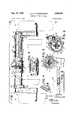
- FIG. 1is a foreshortened plan view, partly in section, of the vehicle spring suspension embodying the present invention, with the pair of wheels at opposite sides respecice tively and with portion of two main frame members of the vehicle being indicated by broken lines;
- FIG. 2is a section on line 22 of FIG. 1 drawn to a slightly larger scale
- FIG. 3is a fragmentary plan view, corresponding in part to FIG. 1, but with the cap and the adjustable locking plate at the center portion of the assembly removed, and with a portion of the housing for the center locking ring broken away;
- FIG. 4is a perspective view showing the adjustable locking plate by itself drawn to a slightly larger scale
- FIG. 5is a section on line 55 of FIG. 1 drawn to the same scale as FIG. 2;
- FIG. 6is a diagrammatic side elevation of one of the wheel-carrying arms taken on line 6-6 of FIG. 1 but drawn to a much smaller scale with the vehicle wheel indicated by broken lines;
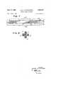
- FIG. 7is a fragmentary elevation of portion of a slightly modified form in which the spring assembly itself may be made before being secured in place in the housing;
- FIG. 8is a cross section on line 88 of FIG. 7.
- the torsion springindicated as a whole by the reference character 10, is mounted in a composite tubular housing 11, which extends transversely of the vehicle frame and which is rigidly secured near its opposite ends respectively to the longitudinally-extending main frame members indicated by the broken lines 12 and 13 (the housing 11 being secured to these main frame members 12 and 13 by suitable means not shown).
- the housing 11is composed of a pair of co-axial tubes 14 and 15, the inner ends of which are rigidly secured, for example by welding, within the corresponding ends of a central cylindrical housing member 16.
- the wall of the central cylindrical housing member 16is provided with a rectangular opening 16' (see also FIGS. 2 and 3) for a reason which will be apparent later.
- the axles 17 and 18 for the wheels W1 and W2 on opposite sides of the vehicleare mounted in a pair of trailing wheel-carrying arms 19 and 20 respectively.
- Each of these armshas an integral tubular journal portion 19 and 20 respectively adapted to be rotatab-ly mounted in the outer ends of the tube members 14 and 15 respectively of the composite housing 11.
- the torsion spring 10is a composite member formed of a plurality of identical groups (for example five in the particular spring illustrated) of identical flat torsion elements or leaves, with the identical elements of each group arranged in nested or superimposed arrangement.
- the composite torsion spring 10consists of a central or core group '21, containing individual identical spring leaves or torsion elements, and four similar groups of identical spring elements 22, 23, 24 and 25 extending longitudinally along on the periphery of the core group.
- the surrounding groups of spring elements 22, 23, 24 and 25normally extend in planes that, as closely as possible, are positioned radially with respect to the center axis of the composite spring assembly. This is a very important feature of the invention and will be referred to again later.
- the five groups of spring leaves or elementsextend through channels provided in a central locking ring 26 (see FIGS. 1 and 3 in addition to FIG. 2), which locking ring is mounted in the central cylindrical housing member 16 (and the five groups also extend through similar channels in end locking rings mentioned presently).
- the central locking ringholds the various groups 21, 22, 23, 24 and 25 together and maintains each one of the surrounding groups in its proper relative position with respect to the others (this being true of the end locking rings also).
- the central locking ringby being provided with means for locking the ring against rotation in the central cylindrical housing member 16, holds the central portion of the composite torrsion spring 10 against rotation and thus in effect provides a pair of composite torsion spring elements extending from the central locking ring 26 and housing member 16 to the trailing wheel-carrying arms 19 and 20 respectively.
- the central locking ring 26is provided with a substantially horizontal slot 27 (FIGS. 2 and 3) which serves as a seat for the inwardly-extending edge portion of an adjustable locking plate 28.
- This locking plate 28extends through the window opening 16' (FIGS. 2 and 3) in the stationary central housing member 16, and carries an upper curved, longitudinally-extending guide bar 29, which is longer than the plate 28, which is also accommodated in the window opening 16'.
- a substantially semi-cylindrical cap 30(FIGS. 1 and 2) is removably mounted on the central housing member 16 by suitable screws 31.
- This capis also provided with a rectangular window 30' of smaller dimension than the vwindow 16, and the cap extends over the side portions of prevents the locking plate 28 from dropping out of place in the central locking ring 26.
- the cap 30is provided with an integral outwardly-extending bracket 32 (FIGS. 1 and 2) located at the top of the window opening 30, which carries an adjustable set screw 33. The bottom end of this set screw bears against the locking plate 28 and holds the locking plate, and therewith the locking ring 26 and the central portion of the composite torsion spring 10, against rotation (in counter-clockwise direction as viewed in FIG. 2), and thus in opposition to the rotational torque imposed at the ends of the composite torsion spring by the wheel-carrying arms 19 and 20.
- An end locking ring 34(FIGS. 1 and for each outer end of the composite torsion spring is secured in each of the tubular journal portions 19' and 20' of the wheelcarrying arms 19 and 20, being firmly secured therein by suitable holding screws 35.
- these end rings 34are provided with channels for the groups of elements making up the composite torson spring 10 in the same way as the central locking ring 26, and, like the central locking ring, these end locking rings maintain the groups of elements in proper relative position with respect to each other, causing all the groups and all the spring elements in the groups to cooperate and function
- the composite stationary tubular housing 11 for the composite torsion springis provided with suitable grease nipples, one :of these being indicated at 40 in FIG. 1.
- stop rings 14' andare welded to the ends of the housing tubes 14 and 15 respectively, and these rings have limit stops adapted to engage lugs 38 and 39 secured on the wheelcarrying arms 19 and 20 respectively.
- FIGS. 7 and 8A further modification for obtaining additional twist in the spring members in carrying out of the invention is illustrated in FIGS. 7 and 8.
- the members in the outer groups 22', 23', 24'. and 25'are bent away from the central core group 21 or bowed so as to cause a curved space to be set up between each outer group and the central core group When the groups are assembled. This would be done only when the spring assembly is set up with the ceneral locking ring or retainer as previously described, and the curves of the outer groups would end at the center and outer ends of the assembly, the retainer at the center and the retainers at the outer ends then tending to hold the outer groups against the central core group.
- Such curving of the members in the outer groupswould make the outer edges of such members longer than the inner edges and thus allow for greater travel of the outer edges, and, as previously mentioned, the outer edges travel further than the inner edges when the assembly is under torsion.
- a central coreextending along the longitudinal axis of the torsion spring assembly, said core consisting of a plurality of identical superimposed flat spring elements, a plurality of groups of superimposed fiat spring elements symmetrically positioned about said core, at least one of said flat spring elements in each of said latter mentioned groups extending substantially radially with respect to the axis of the torsion spring assembly, whereby a torsional twist imposed on said spring assembly will cause torsional twist to be imposed on said spring elements in said latter mentioned groups without any appreciable bending of said elements of said latter mentioned groups in a lateral direction, locking means for holding the central portion of said torsion spring assembly against rotation by torsional twists imposed on the ends of said torsion spring assembly, said locking means including a locking ring extending around said torsion spring assembly containing channels for said groups of said elements, adjustable means for partially rotating said locking ring in a direction opposite the direction of torsional twist imposed on said tor
- each of said torsion arm assembliesincluding a locking ring on said torsion spring assembly similar to said first mentioned central locking ring, and a vehicle wheel carried by each of said torsion arm assemblies.
- a torsion spring assembly for a vehicle wheel suspensionincluding a plurality of identical groups of superimposed fiat spring elements, one of said groups constituting a core group extending along the axis of the torsion spring assembly, the other groups symmetrically positioned about said core group, at least one of said flat spring elements in each of said other groups extending substantially radially with respect to the axis of the torsion spring assembly, whereby a torsional twist imposed on said torsion spring assembly will cause torsional twist to be imposed on said spring elements in said other groups without any appreciable bending of said elements of said other groups in a lateral direction, locking means holding the central portion of said torsion spring assembly against rotation by torsion twists imposed on the ends of said torsion spring assembly, said locking means including a locking ring extending around said torsion springassembly and containing channels for said groups of said elements, a stationary housing assembly secured to the frame of the vehicle for said torsion spring assembly, a central cylindrical housing member in said housing assembly
- a composite torsion spring assemblyincluding a core group of superimposed fiat spring elements, and four identical outer groups of superimposed flat spring elements extending along the four sides of said core group respectively, at least one of said flat spring elements in each of said outer groups extending radially with respect to the axis of the entire assembly, said outer groups being formed with a slight outward bow with respect to the adjacent side of said core group, and means holding each of said outer groups pressed against the adjacent side of said core group near each end of the bow of the group.
Landscapes
- Engineering & Computer Science (AREA)
- Mechanical Engineering (AREA)
- General Engineering & Computer Science (AREA)
- Vehicle Body Suspensions (AREA)
- Springs (AREA)
Description
Claims (1)
Priority Applications (1)
| Application Number | Priority Date | Filing Date | Title |
|---|---|---|---|
| US292282AUS3207497A (en) | 1963-07-02 | 1963-07-02 | Torsion spring assembly |
Applications Claiming Priority (1)
| Application Number | Priority Date | Filing Date | Title |
|---|---|---|---|
| US292282AUS3207497A (en) | 1963-07-02 | 1963-07-02 | Torsion spring assembly |
Publications (1)
| Publication Number | Publication Date |
|---|---|
| US3207497Atrue US3207497A (en) | 1965-09-21 |
Family
ID=23124005
Family Applications (1)
| Application Number | Title | Priority Date | Filing Date |
|---|---|---|---|
| US292282AExpired - LifetimeUS3207497A (en) | 1963-07-02 | 1963-07-02 | Torsion spring assembly |
Country Status (1)
| Country | Link |
|---|---|
| US (1) | US3207497A (en) |
Cited By (36)
| Publication number | Priority date | Publication date | Assignee | Title |
|---|---|---|---|---|
| US4140333A (en)* | 1976-04-30 | 1979-02-20 | Regie Nationale Des Usines Renault | Rear-axle structure for automotive vehicles |
| US4152011A (en)* | 1976-10-09 | 1979-05-01 | Honda Giken Kogyo Kabushiki Kaisha | Characteristic compensating device for air springs for automotive suspension use |
| US4863148A (en)* | 1987-10-27 | 1989-09-05 | Hufnagel Douglas G | Apparatus for adjustment of automobile torsion bar suspension assembly |
| US5163701A (en)* | 1991-09-09 | 1992-11-17 | Csn Manufacturing, Inc. | Torsion spring vehicle suspension |
| US5326128A (en)* | 1991-09-09 | 1994-07-05 | Csn Manufacturing, Inc. | Variable-width torsion spring axle |
| EP0649375A4 (en)* | 1992-07-07 | 1995-02-06 | Curtiss W Henschen | Multiple stage torsion axle. |
| US5443247A (en)* | 1994-05-20 | 1995-08-22 | The United States Of America As Represented By The Administrator, National Aeronautics And Space Administration | Tuneable rotating unbalanced mass device |
| US5910720A (en)* | 1995-06-29 | 1999-06-08 | Massachusetts Institute Of Technology | Cross-shaped torsional spring |
| US20100312363A1 (en)* | 2005-03-31 | 2010-12-09 | Massachusetts Institute Of Technology | Powered Artificial Knee with Agonist-Antagonist Actuation |
| US20110089658A1 (en)* | 2008-06-19 | 2011-04-21 | Zf Friedrichshafen Ag | Stabilizer for a utility vehicle |
| US8191911B1 (en)* | 2009-02-18 | 2012-06-05 | Norm Reynolds | Multiple torsion bar cartridge suspension systems applications |
| WO2012090010A3 (en)* | 2010-12-31 | 2012-09-27 | Hatzikakidis A Dimitrios | Automotive torsion bar made up of sections. |
| US8287477B1 (en) | 2003-09-25 | 2012-10-16 | Massachusetts Institute Of Technology | Active ankle foot orthosis |
| US8419804B2 (en) | 2008-09-04 | 2013-04-16 | Iwalk, Inc. | Hybrid terrain-adaptive lower-extremity systems |
| US8512415B2 (en) | 2005-03-31 | 2013-08-20 | Massachusetts Institute Of Technology | Powered ankle-foot prothesis |
| US8551184B1 (en) | 2002-07-15 | 2013-10-08 | Iwalk, Inc. | Variable mechanical-impedance artificial legs |
| US8734528B2 (en) | 2005-03-31 | 2014-05-27 | Massachusetts Institute Of Technology | Artificial ankle-foot system with spring, variable-damping, and series-elastic actuator components |
| US20140252740A1 (en)* | 2011-11-16 | 2014-09-11 | Saf-Holland Gmbh | Chassis System for Commercial Vehicles |
| US8864846B2 (en) | 2005-03-31 | 2014-10-21 | Massachusetts Institute Of Technology | Model-based neuromechanical controller for a robotic leg |
| US8870967B2 (en) | 2005-03-31 | 2014-10-28 | Massachusetts Institute Of Technology | Artificial joints using agonist-antagonist actuators |
| US9032635B2 (en) | 2011-12-15 | 2015-05-19 | Massachusetts Institute Of Technology | Physiological measurement device or wearable device interface simulator and method of use |
| US9060883B2 (en) | 2011-03-11 | 2015-06-23 | Iwalk, Inc. | Biomimetic joint actuators |
| US9221177B2 (en) | 2012-04-18 | 2015-12-29 | Massachusetts Institute Of Technology | Neuromuscular model-based sensing and control paradigm for a robotic leg |
| US9333097B2 (en) | 2005-03-31 | 2016-05-10 | Massachusetts Institute Of Technology | Artificial human limbs and joints employing actuators, springs, and variable-damper elements |
| US9687377B2 (en) | 2011-01-21 | 2017-06-27 | Bionx Medical Technologies, Inc. | Terrain adaptive powered joint orthosis |
| US9693883B2 (en) | 2010-04-05 | 2017-07-04 | Bionx Medical Technologies, Inc. | Controlling power in a prosthesis or orthosis based on predicted walking speed or surrogate for same |
| US9737419B2 (en) | 2011-11-02 | 2017-08-22 | Bionx Medical Technologies, Inc. | Biomimetic transfemoral prosthesis |
| US9839552B2 (en) | 2011-01-10 | 2017-12-12 | Bionx Medical Technologies, Inc. | Powered joint orthosis |
| US10080672B2 (en) | 2005-03-31 | 2018-09-25 | Bionx Medical Technologies, Inc. | Hybrid terrain-adaptive lower-extremity systems |
| US10285828B2 (en) | 2008-09-04 | 2019-05-14 | Bionx Medical Technologies, Inc. | Implementing a stand-up sequence using a lower-extremity prosthesis or orthosis |
| US10307272B2 (en) | 2005-03-31 | 2019-06-04 | Massachusetts Institute Of Technology | Method for using a model-based controller for a robotic leg |
| US10485681B2 (en) | 2005-03-31 | 2019-11-26 | Massachusetts Institute Of Technology | Exoskeletons for running and walking |
| US10531965B2 (en) | 2012-06-12 | 2020-01-14 | Bionx Medical Technologies, Inc. | Prosthetic, orthotic or exoskeleton device |
| US10537449B2 (en) | 2011-01-12 | 2020-01-21 | Bionx Medical Technologies, Inc. | Controlling powered human augmentation devices |
| US11278433B2 (en) | 2005-03-31 | 2022-03-22 | Massachusetts Institute Of Technology | Powered ankle-foot prosthesis |
| US12181239B2 (en) | 2019-07-02 | 2024-12-31 | BAE Systems Hägglunds Aktiebolag | Arrangement and method for balancing a gun barrel of a vehicle mounted weapon system |
Citations (7)
| Publication number | Priority date | Publication date | Assignee | Title |
|---|---|---|---|---|
| GB218114A (en)* | 1923-07-16 | 1924-07-03 | George Carwardine | Improvements in suspensions for automobiles and the like |
| US2164096A (en)* | 1936-04-04 | 1939-06-27 | Briggs Mfg Co | Rear wheel suspension and engine mounting |
| US2175562A (en)* | 1934-01-03 | 1939-10-10 | Porsche Gmbh | Springing arrangement |
| GB519524A (en)* | 1937-08-26 | 1940-03-29 | Walther Doblhoff | Improvements in or relating to springs |
| GB613044A (en)* | 1944-03-02 | 1948-11-22 | Cfcmug | Improvements in or relating to frictionless suspensions for the movable elements of measuring apparatus, relays or analogous apparatus |
| FR1043686A (en)* | 1950-10-17 | 1953-11-10 | Vehicle torsion bar suspension | |
| US3081991A (en)* | 1960-07-12 | 1963-03-19 | Northrop Corp | Transverse supported torsion bar |
- 1963
- 1963-07-02USUS292282Apatent/US3207497A/ennot_activeExpired - Lifetime
Patent Citations (7)
| Publication number | Priority date | Publication date | Assignee | Title |
|---|---|---|---|---|
| GB218114A (en)* | 1923-07-16 | 1924-07-03 | George Carwardine | Improvements in suspensions for automobiles and the like |
| US2175562A (en)* | 1934-01-03 | 1939-10-10 | Porsche Gmbh | Springing arrangement |
| US2164096A (en)* | 1936-04-04 | 1939-06-27 | Briggs Mfg Co | Rear wheel suspension and engine mounting |
| GB519524A (en)* | 1937-08-26 | 1940-03-29 | Walther Doblhoff | Improvements in or relating to springs |
| GB613044A (en)* | 1944-03-02 | 1948-11-22 | Cfcmug | Improvements in or relating to frictionless suspensions for the movable elements of measuring apparatus, relays or analogous apparatus |
| FR1043686A (en)* | 1950-10-17 | 1953-11-10 | Vehicle torsion bar suspension | |
| US3081991A (en)* | 1960-07-12 | 1963-03-19 | Northrop Corp | Transverse supported torsion bar |
Cited By (63)
| Publication number | Priority date | Publication date | Assignee | Title |
|---|---|---|---|---|
| US4140333A (en)* | 1976-04-30 | 1979-02-20 | Regie Nationale Des Usines Renault | Rear-axle structure for automotive vehicles |
| US4152011A (en)* | 1976-10-09 | 1979-05-01 | Honda Giken Kogyo Kabushiki Kaisha | Characteristic compensating device for air springs for automotive suspension use |
| US4863148A (en)* | 1987-10-27 | 1989-09-05 | Hufnagel Douglas G | Apparatus for adjustment of automobile torsion bar suspension assembly |
| US5163701A (en)* | 1991-09-09 | 1992-11-17 | Csn Manufacturing, Inc. | Torsion spring vehicle suspension |
| WO1993004787A1 (en)* | 1991-09-09 | 1993-03-18 | Cns Manufacturing, Inc. | Torsion spring vehicle suspension |
| US5326128A (en)* | 1991-09-09 | 1994-07-05 | Csn Manufacturing, Inc. | Variable-width torsion spring axle |
| EP0649375A4 (en)* | 1992-07-07 | 1995-02-06 | Curtiss W Henschen | Multiple stage torsion axle. |
| US5443247A (en)* | 1994-05-20 | 1995-08-22 | The United States Of America As Represented By The Administrator, National Aeronautics And Space Administration | Tuneable rotating unbalanced mass device |
| US5910720A (en)* | 1995-06-29 | 1999-06-08 | Massachusetts Institute Of Technology | Cross-shaped torsional spring |
| US8551184B1 (en) | 2002-07-15 | 2013-10-08 | Iwalk, Inc. | Variable mechanical-impedance artificial legs |
| US9668888B2 (en) | 2003-09-25 | 2017-06-06 | Massachusetts Institute Of Technology | Active ankle foot orthosis |
| US10695256B2 (en) | 2003-09-25 | 2020-06-30 | Massachusetts Institute Of Technology | Motorized limb assistance device |
| US8808214B2 (en) | 2003-09-25 | 2014-08-19 | Massachusetts Institute Of Technology | Active ankle foot orthosis |
| US8287477B1 (en) | 2003-09-25 | 2012-10-16 | Massachusetts Institute Of Technology | Active ankle foot orthosis |
| US8376971B1 (en) | 2003-09-25 | 2013-02-19 | Massachusetts Institute Of Technology | Active ankle foot orthosis |
| US8551029B1 (en) | 2003-09-25 | 2013-10-08 | Massachusetts Institute Of Technology | Active ankle foot orthosis |
| US20100312363A1 (en)* | 2005-03-31 | 2010-12-09 | Massachusetts Institute Of Technology | Powered Artificial Knee with Agonist-Antagonist Actuation |
| US10485681B2 (en) | 2005-03-31 | 2019-11-26 | Massachusetts Institute Of Technology | Exoskeletons for running and walking |
| US8500823B2 (en) | 2005-03-31 | 2013-08-06 | Massachusetts Institute Of Technology | Powered artificial knee with agonist-antagonist actuation |
| US11273060B2 (en) | 2005-03-31 | 2022-03-15 | Massachusetts Institute Of Technology | Artificial ankle-foot system with spring, variable-damping, and series-elastic actuator components |
| US9539117B2 (en) | 2005-03-31 | 2017-01-10 | Massachusetts Institute Of Technology | Method for controlling a robotic limb joint |
| US8734528B2 (en) | 2005-03-31 | 2014-05-27 | Massachusetts Institute Of Technology | Artificial ankle-foot system with spring, variable-damping, and series-elastic actuator components |
| US11278433B2 (en) | 2005-03-31 | 2022-03-22 | Massachusetts Institute Of Technology | Powered ankle-foot prosthesis |
| US11491032B2 (en) | 2005-03-31 | 2022-11-08 | Massachusetts Institute Of Technology | Artificial joints using agonist-antagonist actuators |
| US8864846B2 (en) | 2005-03-31 | 2014-10-21 | Massachusetts Institute Of Technology | Model-based neuromechanical controller for a robotic leg |
| US8870967B2 (en) | 2005-03-31 | 2014-10-28 | Massachusetts Institute Of Technology | Artificial joints using agonist-antagonist actuators |
| US10588759B2 (en) | 2005-03-31 | 2020-03-17 | Massachusetts Institute Of Technology | Artificial human limbs and joints employing actuators, springs and variable-damper elements |
| US8512415B2 (en) | 2005-03-31 | 2013-08-20 | Massachusetts Institute Of Technology | Powered ankle-foot prothesis |
| US10342681B2 (en) | 2005-03-31 | 2019-07-09 | Massachusetts Institute Of Technology | Artificial ankle-foot system with spring, variable-damping, and series-elastic actuator components |
| US9149370B2 (en) | 2005-03-31 | 2015-10-06 | Massachusetts Institute Of Technology | Powered artificial knee with agonist-antagonist actuation |
| US10307272B2 (en) | 2005-03-31 | 2019-06-04 | Massachusetts Institute Of Technology | Method for using a model-based controller for a robotic leg |
| US10080672B2 (en) | 2005-03-31 | 2018-09-25 | Bionx Medical Technologies, Inc. | Hybrid terrain-adaptive lower-extremity systems |
| US10137011B2 (en) | 2005-03-31 | 2018-11-27 | Massachusetts Institute Of Technology | Powered ankle-foot prosthesis |
| US9333097B2 (en) | 2005-03-31 | 2016-05-10 | Massachusetts Institute Of Technology | Artificial human limbs and joints employing actuators, springs, and variable-damper elements |
| US9339397B2 (en) | 2005-03-31 | 2016-05-17 | Massachusetts Institute Of Technology | Artificial ankle-foot system with spring, variable-damping, and series-elastic actuator components |
| US20110089658A1 (en)* | 2008-06-19 | 2011-04-21 | Zf Friedrichshafen Ag | Stabilizer for a utility vehicle |
| US8684381B2 (en)* | 2008-06-19 | 2014-04-01 | Zf Friedrichshafen Ag | Stabilizer for a utility vehicle |
| US9211201B2 (en) | 2008-09-04 | 2015-12-15 | Iwalk, Inc. | Hybrid terrain-adaptive lower-extremity systems |
| US9345592B2 (en) | 2008-09-04 | 2016-05-24 | Bionx Medical Technologies, Inc. | Hybrid terrain-adaptive lower-extremity systems |
| US9351856B2 (en) | 2008-09-04 | 2016-05-31 | Iwalk, Inc. | Hybrid terrain-adaptive lower-extremity systems |
| US10285828B2 (en) | 2008-09-04 | 2019-05-14 | Bionx Medical Technologies, Inc. | Implementing a stand-up sequence using a lower-extremity prosthesis or orthosis |
| US9554922B2 (en) | 2008-09-04 | 2017-01-31 | Bionx Medical Technologies, Inc. | Hybrid terrain-adaptive lower-extremity systems |
| US10105244B2 (en) | 2008-09-04 | 2018-10-23 | Bionx Medical Technologies, Inc. | Hybrid terrain-adaptive lower-extremity systems |
| US10070974B2 (en) | 2008-09-04 | 2018-09-11 | Bionx Medical Technologies, Inc. | Hybrid terrain-adaptive lower-extremity systems |
| US8419804B2 (en) | 2008-09-04 | 2013-04-16 | Iwalk, Inc. | Hybrid terrain-adaptive lower-extremity systems |
| US8900325B2 (en) | 2008-09-04 | 2014-12-02 | Iwalk, Inc. | Hybrid terrain-adaptive lower-extremity systems |
| US8191911B1 (en)* | 2009-02-18 | 2012-06-05 | Norm Reynolds | Multiple torsion bar cartridge suspension systems applications |
| US10406002B2 (en) | 2010-04-05 | 2019-09-10 | Bionx Medical Technologies, Inc. | Controlling torque in a prosthesis or orthosis based on a deflection of series elastic element |
| US9693883B2 (en) | 2010-04-05 | 2017-07-04 | Bionx Medical Technologies, Inc. | Controlling power in a prosthesis or orthosis based on predicted walking speed or surrogate for same |
| WO2012090010A3 (en)* | 2010-12-31 | 2012-09-27 | Hatzikakidis A Dimitrios | Automotive torsion bar made up of sections. |
| US9839552B2 (en) | 2011-01-10 | 2017-12-12 | Bionx Medical Technologies, Inc. | Powered joint orthosis |
| US10537449B2 (en) | 2011-01-12 | 2020-01-21 | Bionx Medical Technologies, Inc. | Controlling powered human augmentation devices |
| US9687377B2 (en) | 2011-01-21 | 2017-06-27 | Bionx Medical Technologies, Inc. | Terrain adaptive powered joint orthosis |
| US9060883B2 (en) | 2011-03-11 | 2015-06-23 | Iwalk, Inc. | Biomimetic joint actuators |
| US9872782B2 (en) | 2011-03-11 | 2018-01-23 | Bionx Medical Technologies, Inc. | Biomimetic joint actuators |
| US9737419B2 (en) | 2011-11-02 | 2017-08-22 | Bionx Medical Technologies, Inc. | Biomimetic transfemoral prosthesis |
| US9174506B2 (en)* | 2011-11-16 | 2015-11-03 | Saf-Holland Gmbh | Chassis system for commercial vehicles |
| US20140252740A1 (en)* | 2011-11-16 | 2014-09-11 | Saf-Holland Gmbh | Chassis System for Commercial Vehicles |
| US9032635B2 (en) | 2011-12-15 | 2015-05-19 | Massachusetts Institute Of Technology | Physiological measurement device or wearable device interface simulator and method of use |
| US9221177B2 (en) | 2012-04-18 | 2015-12-29 | Massachusetts Institute Of Technology | Neuromuscular model-based sensing and control paradigm for a robotic leg |
| US9975249B2 (en) | 2012-04-18 | 2018-05-22 | Massachusetts Institute Of Technology | Neuromuscular model-based sensing and control paradigm for a robotic leg |
| US10531965B2 (en) | 2012-06-12 | 2020-01-14 | Bionx Medical Technologies, Inc. | Prosthetic, orthotic or exoskeleton device |
| US12181239B2 (en) | 2019-07-02 | 2024-12-31 | BAE Systems Hägglunds Aktiebolag | Arrangement and method for balancing a gun barrel of a vehicle mounted weapon system |
Similar Documents
| Publication | Publication Date | Title |
|---|---|---|
| US3207497A (en) | Torsion spring assembly | |
| US3147990A (en) | Stabilizing system for vehicles | |
| US3137513A (en) | Wheel suspension system for vehicles | |
| US2621057A (en) | Suspension system for vehicles | |
| US2099312A (en) | Spring suspension of independent car wheels, especially for motor vehicles | |
| US2069911A (en) | Vehicle suspension | |
| US2730375A (en) | Independent wheel suspensions for the steerable wheels of motor vehicles | |
| US2179016A (en) | Vehicle | |
| US2782026A (en) | Resilient suspensions for vehicle axle boxes or casings | |
| US2778626A (en) | Torsion spring assembly | |
| US2768002A (en) | Independent wheel suspension for the steerable wheels of automotive vehicles | |
| US2458548A (en) | Wheel suspension for vehicles | |
| US2033493A (en) | Suspension of road wheels of vehicles | |
| US2950103A (en) | Torsion spring device on vehicles | |
| US2078521A (en) | Suspension for multiwheelers | |
| DE2918009A1 (en) | REAR AXLE FOR MOTOR VEHICLES | |
| GB1061121A (en) | Improvements in or relating to vehicle wheel suspension assemblies | |
| US2166368A (en) | Independent wheel suspension for automobiles | |
| US1771488A (en) | Spring suspension for six-wheel vehicles | |
| US2796267A (en) | Transverse compensating bar stabilizer arrangement for vehicle suspensions | |
| US2117401A (en) | Vehicle spring suspension | |
| US2171469A (en) | Automobile | |
| US3315981A (en) | Wheel suspension | |
| US3236514A (en) | Wheel suspension | |
| US2050693A (en) | Spring suspension for vehicles |
Legal Events
| Date | Code | Title | Description |
|---|---|---|---|
| AS | Assignment | Owner name:TA ACQUISITION CORP. SOUTHFIELD, MI A CORP. OF CA Free format text:ASSIGNMENT OF ASSIGNORS INTEREST.;ASSIGNOR:DURA CORPORATION A NY CORP.;REEL/FRAME:004011/0573 Effective date:19820212 | |
| AS | Assignment | Owner name:DURA CORPORATION 26877 NORTHWEST HIGHWAY BOX 267, Free format text:ASSIGNMENT OF ASSIGNORS INTEREST.;ASSIGNOR:DURA CORPORATION, A NY CORP.;REEL/FRAME:004049/0796 Effective date:19820917 | |
| AS | Assignment | Owner name:DURA CORPORATION, 26877 NORTHWEST HIGHWAY, BOX 267 Free format text:ASSIGNMENT OF ASSIGNORS INTEREST.;ASSIGNOR:DURA CORPORATION, A CORP OF CA.;REEL/FRAME:004661/0877 Effective date:19830815 Owner name:DURA CORPORATION, A CORP OF MI., MICHIGAN Free format text:ASSIGNMENT OF ASSIGNORS INTEREST;ASSIGNOR:DURA CORPORATION, A CORP OF CA.;REEL/FRAME:004661/0877 Effective date:19830815 |