US3182717A - Duct-installable heat exchanger - Google Patents
Duct-installable heat exchangerDownload PDFInfo
- Publication number
- US3182717A US3182717AUS147584AUS14758461AUS3182717AUS 3182717 AUS3182717 AUS 3182717AUS 147584 AUS147584 AUS 147584AUS 14758461 AUS14758461 AUS 14758461AUS 3182717 AUS3182717 AUS 3182717A
- Authority
- US
- United States
- Prior art keywords
- duct
- heat exchanger
- panels
- air
- flanges
- Prior art date
- Legal status (The legal status is an assumption and is not a legal conclusion. Google has not performed a legal analysis and makes no representation as to the accuracy of the status listed.)
- Expired - Lifetime
Links
Images
Classifications
- F—MECHANICAL ENGINEERING; LIGHTING; HEATING; WEAPONS; BLASTING
- F24—HEATING; RANGES; VENTILATING
- F24F—AIR-CONDITIONING; AIR-HUMIDIFICATION; VENTILATION; USE OF AIR CURRENTS FOR SCREENING
- F24F13/00—Details common to, or for air-conditioning, air-humidification, ventilation or use of air currents for screening
- F24F13/30—Arrangement or mounting of heat-exchangers
- F—MECHANICAL ENGINEERING; LIGHTING; HEATING; WEAPONS; BLASTING
- F24—HEATING; RANGES; VENTILATING
- F24F—AIR-CONDITIONING; AIR-HUMIDIFICATION; VENTILATION; USE OF AIR CURRENTS FOR SCREENING
- F24F3/00—Air-conditioning systems in which conditioned primary air is supplied from one or more central stations to distributing units in the rooms or spaces where it may receive secondary treatment; Apparatus specially designed for such systems
- F24F3/044—Systems in which all treatment is given in the central station, i.e. all-air systems
- F24F3/048—Systems in which all treatment is given in the central station, i.e. all-air systems with temperature control at constant rate of air-flow
- F24F3/052—Multiple duct systems, e.g. systems in which hot and cold air are supplied by separate circuits from the central station to mixing chambers in the spaces to be conditioned
- F24F3/0525—Multiple duct systems, e.g. systems in which hot and cold air are supplied by separate circuits from the central station to mixing chambers in the spaces to be conditioned in which the air treated in the central station is reheated
Definitions
- This inventionrelates to heat exchangers and particularly to improved mechanisms and arrangements for installing heat exchangers in sheet metal duct work, as for example in air conditioning systems.
- certain air conditioning systemsparticularly large commercial systems, there are provided in the air ducts certain auxiliary heat exchangers for tempering the air prior to its introduction into the rooms being serviced by the conditioning system.
- these auxiliary heat exchangershave been installed by providing each end face of the exchanger with outwardly projecting flanges having punched holes therein.
- a further object of the inventionis to provide a heat exchanger of relatively rigid but lightweight construction to thus adapt the exchanger for installation in conventional sheet metal duct work without placing an excessive mechanical load on the duct walls.
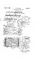
- FIGURE 1is a schematic view illustrating a conventional air conditioning system in which the present invention may be utilized
- FIG. 2is a view illustrating one embodiment of the invention and taken along broken line 2-2 in FIG. 3;
- FIG. 3is a sectional view taken along broken line 3-3 in FIG. 2;
- FIG. 4is a right end elevational view of the FIG. 2 embodiment with a part thereof broken away on line 4-4 in FIG. 2;
- FIG. 5is an enlarged perspective view of a fragmentary portion of the construction shown in FIGS. 2, 3 and 4.
- FIG. 1 of the drawingsthere is shown an air condi-tioning system having aseries of air-treating devices located in the area designated generally by numeral 12 and having a vertically extending riser duct 14 for sup- 3,182,717 Patented May 11, 1965 plying conditioned air to various lateral duct sections designated by numerals 16, 18, 20 and 22.
- duct sections 16 and 18are intended to supply conditioned air to interior rooms of the building, while duct sections 20 and 22 are intended to supply conditioned air to perimeter rooms of the building.
- Sections 16 and 18are equipped with conventional ceilingtype air diffusers 24, while sections 20 and 22 are connected with under-the-window room conditioner units 26.
- each of the duct sections 16 and 18is preferably equipped with an auxiliary heat exchanger 28 constructed as shown in FIGS. 2, 3, 4 and 5.
- heat exchanger 28includes a top panel 30, a bottom panel 32, a right side panel 34, and a left side panel 36.
- Each of the side panelsis provided with an inwardly turned flange 38 which is rigidly affixed to a face portion of one of the top and bottom panels, as by screws or rivets (no-t shown).
- the various panelsare formed of relatively light material such as sheet metal but are rigidified by means of the serpentine coil defined by the various horizontal heat exchange tubes and return bends 42.
- the drawingsshow heat exchange fins only on the end portions of tubes40, but it will be understood that in the actual structure the entire length of each tube is equipped with heat exchange fins.
- the top and bottom panel 30 and 32are equipped with integral ribs 44 which serve both as reinforcement devices and as bafiies to prevent the flowing air from by-passing the heat exchange fin surfaces.
- the vertical edges of panels 34 and 36are directed outwardly at 46 and then at 48 toward the plane defined by the heat exchange tubes 40.
- flange portions 46abut against flange portions 46a which are formed integrally with the duct sections 16a and 161), the arrangement permitting the heat exchanger to be locked in position by sliding the C-shaped members 50 downwardly over the abutting flange areas.
- the duct sections 16a and 15bare each provided with a top wall 52, bottom wall 54 and two side Walls 56 and 58, the arrangement being such that side walls and 58 align with side panels 34 and 36 of the heat exchanger, while top walls 52 and bottom walls 54 overlap edge areas 60 of the corresponding heat exchanger panels. This edge overlapment allows the S-shape-d sealing elements 62 to be interposed between the respective walls and panels for insuring a substantially air-tight joint therebetween.
- Heat exchanger 28is installed as the air duct is being fabricated on the job site.
- the installation of heat exchanger 28involves initially installing the'two sealing elements 62 on the edges of the top and bottom walls 52 and 54 of duct section 16a.
- the heat exchangeris then manipulated until edge portions 60 thereof are disposed in the S-shaped sealing elements, after which the C-shaped clamps 50 are manually telescoped downwardly over the oppositely facing flanges 48 and 48a of the heat exchanger and duct section; this procedure locks the heat exchanger onto section 16a.
- the next duct section 16bmay then be installed by positioning the appropriate sealing elements 62 and clamp elements 50 in the manner previously described.
- sealing element 62 and clamping element 50are conventional structures commonly utilized in the installation of sheet metal air conditioning ducts so that the invention may be utilizedwith existing duct work designs.
- the heat exchanger of this inventioncan be constructed of various sizes and with various numbers of heat exchange tubes 40.
- the horizontal distance between panels 34 and 36can in some practical forms vary from about twelve inche to about forty-two inches, and the vertical distance between panels 30 and 32 can vary from about six inches to fifteen inches.
- the gauge of the material for panels 30, 32, 34 and 36can be varied to suit conditions.
- An air conditioning systemcomprising two horizontally aligned spaced rectangular ducts, each having a top wall, two side walls, a bottom wall and vertical flanges formed on duct side walls extending outwardly from the edges of said side walls and then parallel therewith in opposite directions; a rectangular heat exchanger interposed between the two ducts and including a sheet metal top panel, a sheet metal bottom panel, and two sheet metal side panels having their upper and lower edge portions aflixed to respective ones of the top and bottom panels; said side panels being of lesser horizontal dimension than the top and bottom panels 30 that the free edge portions of the top and bottom panels extend horizontally beyond the limits of the side panels into overlapping relation with edge portions of the duct top and bottom walls; each of said side panels lying in the same vertical planes as the corresponding side walls of the duct sections; each of said side panels having vertical flanges extending outwardly from their free edges and then parallel to the panel surfaces so that the outwardly extending portions of the panel flanges abut against the outwardly extending
Landscapes
- Engineering & Computer Science (AREA)
- Chemical & Material Sciences (AREA)
- Combustion & Propulsion (AREA)
- Mechanical Engineering (AREA)
- General Engineering & Computer Science (AREA)
- Duct Arrangements (AREA)
Description
Priority Applications (1)
| Application Number | Priority Date | Filing Date | Title |
|---|---|---|---|
| US147584AUS3182717A (en) | 1961-10-25 | 1961-10-25 | Duct-installable heat exchanger |
Applications Claiming Priority (1)
| Application Number | Priority Date | Filing Date | Title |
|---|---|---|---|
| US147584AUS3182717A (en) | 1961-10-25 | 1961-10-25 | Duct-installable heat exchanger |
Publications (1)
| Publication Number | Publication Date |
|---|---|
| US3182717Atrue US3182717A (en) | 1965-05-11 |
Family
ID=22522149
Family Applications (1)
| Application Number | Title | Priority Date | Filing Date |
|---|---|---|---|
| US147584AExpired - LifetimeUS3182717A (en) | 1961-10-25 | 1961-10-25 | Duct-installable heat exchanger |
Country Status (1)
| Country | Link |
|---|---|
| US (1) | US3182717A (en) |
Cited By (6)
| Publication number | Priority date | Publication date | Assignee | Title |
|---|---|---|---|---|
| US20080164006A1 (en)* | 2007-01-10 | 2008-07-10 | Karamanos John C | Embedded heat exchanger for heating, ventilatiion, and air conditioning (hvac) systems and methods |
| US20110155354A1 (en)* | 2005-05-06 | 2011-06-30 | John Chris Karamanos | Hvac system and zone control unit |
| US8596083B2 (en) | 2005-05-06 | 2013-12-03 | John C. Karamanos | Shipping and installation for heating, ventilation, and air conditioning (HVAC) |
| US9222862B2 (en) | 2013-03-12 | 2015-12-29 | John C. Karamanos | Piping stick systems and methods |
| USRE46708E1 (en)* | 2002-03-06 | 2018-02-13 | John C. Karamanos | Embedded heat exchanger for heating, ventilation, and air conditioning (HVAC) systems and methods |
| US11841159B2 (en) | 2002-03-06 | 2023-12-12 | John Chris Karamanos | Embedded heat exchanger with support mechanism |
Citations (16)
| Publication number | Priority date | Publication date | Assignee | Title |
|---|---|---|---|---|
| US641580A (en)* | 1899-04-24 | 1900-01-16 | Michael Cummins | Flue or pipe coupling. |
| US760216A (en)* | 1903-12-23 | 1904-05-17 | Harry H Laws | Flue or duct. |
| US1040442A (en)* | 1912-07-19 | 1912-10-08 | William T Shannon | Metal culvert. |
| US1817948A (en)* | 1929-11-16 | 1931-08-11 | Carrier Construction Company I | Heat exchange device |
| US2025802A (en)* | 1934-08-25 | 1935-12-31 | Aeriet Air Conditioner Company | Air conditioner |
| US2110024A (en)* | 1936-08-29 | 1938-03-01 | Gen Electric | Heat exchange unit |
| US2153267A (en)* | 1936-04-09 | 1939-04-04 | American Blower Corp | Air conditioning apparatus |
| US2319062A (en)* | 1943-05-11 | Mb conditioning apparatus | ||
| US2354131A (en)* | 1938-03-19 | 1944-07-18 | Lul Products Inc | Refrigerating apparatus |
| US2475604A (en)* | 1943-11-02 | 1949-07-12 | Foster Wheeler Corp | Heat exchange apparatus |
| US2491700A (en)* | 1945-11-10 | 1949-12-20 | Zwerling Harry | Braced conduit construction |
| US2568278A (en)* | 1949-03-30 | 1951-09-18 | Charles J Favot | Electrical warm air recirculating room heater |
| US2752950A (en)* | 1950-09-08 | 1956-07-03 | Coulters Thomas Carey | Connection means for heating and ventilating ducts |
| US2956587A (en)* | 1958-11-17 | 1960-10-18 | B & C Metal Stamping Company | Sectional duct |
| US3012762A (en)* | 1958-08-18 | 1961-12-12 | Lennox Ind Inc | Modular units for air heating, cooling and ventilating systems |
| US3097507A (en)* | 1963-07-16 | Adjustable evaporator assemblies for air conditioners |
- 1961
- 1961-10-25USUS147584Apatent/US3182717A/ennot_activeExpired - Lifetime
Patent Citations (16)
| Publication number | Priority date | Publication date | Assignee | Title |
|---|---|---|---|---|
| US3097507A (en)* | 1963-07-16 | Adjustable evaporator assemblies for air conditioners | ||
| US2319062A (en)* | 1943-05-11 | Mb conditioning apparatus | ||
| US641580A (en)* | 1899-04-24 | 1900-01-16 | Michael Cummins | Flue or pipe coupling. |
| US760216A (en)* | 1903-12-23 | 1904-05-17 | Harry H Laws | Flue or duct. |
| US1040442A (en)* | 1912-07-19 | 1912-10-08 | William T Shannon | Metal culvert. |
| US1817948A (en)* | 1929-11-16 | 1931-08-11 | Carrier Construction Company I | Heat exchange device |
| US2025802A (en)* | 1934-08-25 | 1935-12-31 | Aeriet Air Conditioner Company | Air conditioner |
| US2153267A (en)* | 1936-04-09 | 1939-04-04 | American Blower Corp | Air conditioning apparatus |
| US2110024A (en)* | 1936-08-29 | 1938-03-01 | Gen Electric | Heat exchange unit |
| US2354131A (en)* | 1938-03-19 | 1944-07-18 | Lul Products Inc | Refrigerating apparatus |
| US2475604A (en)* | 1943-11-02 | 1949-07-12 | Foster Wheeler Corp | Heat exchange apparatus |
| US2491700A (en)* | 1945-11-10 | 1949-12-20 | Zwerling Harry | Braced conduit construction |
| US2568278A (en)* | 1949-03-30 | 1951-09-18 | Charles J Favot | Electrical warm air recirculating room heater |
| US2752950A (en)* | 1950-09-08 | 1956-07-03 | Coulters Thomas Carey | Connection means for heating and ventilating ducts |
| US3012762A (en)* | 1958-08-18 | 1961-12-12 | Lennox Ind Inc | Modular units for air heating, cooling and ventilating systems |
| US2956587A (en)* | 1958-11-17 | 1960-10-18 | B & C Metal Stamping Company | Sectional duct |
Cited By (14)
| Publication number | Priority date | Publication date | Assignee | Title |
|---|---|---|---|---|
| US10767893B2 (en) | 2002-03-06 | 2020-09-08 | John Chris Karamanos | Embedded heat exchanger with support mechanism |
| US12264839B2 (en) | 2002-03-06 | 2025-04-01 | John Chris Karamanos | Pre-piped thermal transfer unit with support mechanism |
| US11841159B2 (en) | 2002-03-06 | 2023-12-12 | John Chris Karamanos | Embedded heat exchanger with support mechanism |
| USRE46708E1 (en)* | 2002-03-06 | 2018-02-13 | John C. Karamanos | Embedded heat exchanger for heating, ventilation, and air conditioning (HVAC) systems and methods |
| US20140325844A1 (en)* | 2003-09-11 | 2014-11-06 | John Chris Karamanos | Embedded heat exchanger for heating, ventilation, and air conditioning (hvac) systems and methods |
| US9694452B2 (en)* | 2003-09-11 | 2017-07-04 | John Chris Karamanos | Embedded heat exchanger for heating, ventilation, and air conditioning (HVAC) systems and methods |
| US20110155354A1 (en)* | 2005-05-06 | 2011-06-30 | John Chris Karamanos | Hvac system and zone control unit |
| US8596083B2 (en) | 2005-05-06 | 2013-12-03 | John C. Karamanos | Shipping and installation for heating, ventilation, and air conditioning (HVAC) |
| US9459015B2 (en) | 2005-05-06 | 2016-10-04 | John Chris Karamanos | HVAC system and zone control unit |
| US8714236B2 (en)* | 2007-01-10 | 2014-05-06 | John C. Karamanos | Embedded heat exchanger for heating, ventilatiion, and air conditioning (HVAC) systems and methods |
| US20080164006A1 (en)* | 2007-01-10 | 2008-07-10 | Karamanos John C | Embedded heat exchanger for heating, ventilatiion, and air conditioning (hvac) systems and methods |
| US10317097B2 (en) | 2013-03-12 | 2019-06-11 | John C. Karamanos | Piping stick systems and methods |
| US10001287B2 (en) | 2013-03-12 | 2018-06-19 | John C. Karamanos | Piping stick systems |
| US9222862B2 (en) | 2013-03-12 | 2015-12-29 | John C. Karamanos | Piping stick systems and methods |
Similar Documents
| Publication | Publication Date | Title |
|---|---|---|
| US2662743A (en) | Suspended panel type air conditioner | |
| US2661677A (en) | Register frame | |
| US3537485A (en) | Duct modules for climate control system | |
| US3182717A (en) | Duct-installable heat exchanger | |
| US1915805A (en) | Radiator | |
| EP2808638A1 (en) | Heat exchanger and method for fixing | |
| US4941528A (en) | Ceiling made of metal panels | |
| US5529092A (en) | Air duct turning vane and rail assembly | |
| US5749190A (en) | HVAC register box | |
| US2352876A (en) | Collapsible conduit | |
| US4016729A (en) | Curb-duct for roof top air conditioners | |
| US4169500A (en) | Modular air conditioning apparatus | |
| US1979543A (en) | Register | |
| EP0201473B1 (en) | Radiator-convector element | |
| KR20200120362A (en) | Corner bracket for air duct and assembling method of air duct using the same | |
| EP0555494A1 (en) | Radiator with air duct | |
| JP2539332B2 (en) | Air-conditioning outlet for ceiling | |
| DE3877207T2 (en) | HEATING OR COOLING ARRANGEMENT. | |
| US1853314A (en) | Heating apparatus | |
| FI97318C (en) | Heat exchange device | |
| US3130752A (en) | Air duct header | |
| US2450184A (en) | Air conditioning grille or register assembly | |
| US20220275967A1 (en) | Insulated register box assembly having radius clip disc | |
| CN214198888U (en) | Air outlet inside casing structure | |
| US2147854A (en) | Fluid circulating system |
Legal Events
| Date | Code | Title | Description |
|---|---|---|---|
| AS | Assignment | Owner name:MERCANTILE TEXAS CREDIT CORPORATION; MERCANTILE CO Free format text:ASSIGNMENT OF ASSIGNORS INTEREST.;ASSIGNOR:SYNDER GENERAL CORPORATION;REEL/FRAME:003985/0168 Effective date:19820401 Owner name:MERCANTILE TEXAS CREDIT CORPORATION, TEXAS Free format text:ASSIGNMENT OF ASSIGNORS INTEREST;ASSIGNOR:SYNDER GENERAL CORPORATION;REEL/FRAME:003985/0168 Effective date:19820401 | |
| AS | Assignment | Owner name:SNYDER GENERAL CORPORATION, A CORP. OF TEX. Free format text:ASSIGNS THE ENTIRE INTEREST, AS OF APRIL 2, 1982 SUBJECT TO LICENSES AND CONDITIONS RECITED;ASSIGNOR:SINGER COMPANY, THE;REEL/FRAME:004051/0894 Effective date:19820402 Owner name:SNYDER GENERAL CORPORATION Free format text:ASSIGNS THE ENTIRE INTEREST, AS OF APRIL 2, 1982 SUBJECT TO LICENSES AND CONDITIONS RECITED, SEE DOCUMENT FOR DETAILS;ASSIGNOR:SINGER COMPANY, THE;REEL/FRAME:004051/0894 Effective date:19820402 | |
| AS | Assignment | Owner name:CITICORP INDUSTRIAL CREDIT, INC., 717 NORTH HARWOO Free format text:SECURITY INTEREST;ASSIGNOR:SYNDER GENERAL CORPORATION A TX CORP;REEL/FRAME:004307/0351 Effective date:19840726 | |
| AS | Assignment | Owner name:CITICORP NORTH AMERICA, INC., NEW YORK Free format text:SECURITY INTEREST;ASSIGNOR:SNYDERGENERAL CORPORATION, A MN CORP.;REEL/FRAME:005013/0592 Effective date:19881117 | |
| AS | Assignment | Owner name:SNYDERGENERAL CORPORATION, A MN CORP., TEXAS Free format text:RELEASED BY SECURED PARTY;ASSIGNOR:MCREDIT;REEL/FRAME:005003/0183 Effective date:19881115 | |
| AS | Assignment | Owner name:MCQUAY INC., A CORP. OF MINNESOTA, MINNESOTA Free format text:RELEASED BY SECURED PARTY;ASSIGNOR:CITICORP NORTH AMERICA, INC.;REEL/FRAME:005278/0013 Effective date:19881117 Owner name:SNYDERGENERAL CORPORATION, A CORP. OF MINNESOTA, T Free format text:RELEASED BY SECURED PARTY;ASSIGNOR:CITICORP NORTH AMERICA, INC.;REEL/FRAME:005278/0013 Effective date:19881117 | |
| AS | Assignment | Owner name:SNYDERGENERAL CORPORATION A CORP. OF DELAWARE Free format text:RELEASE BY SECOND PARTY OF A SECURITY AGREEMENT RECORDED AT REEL 5013 FRAME 592.;ASSIGNOR:CITICORP NORTH AMERICA, INC. A CORP. OF DELAWARE;REEL/FRAME:006104/0270 Effective date:19920326 |