US2893759A - Conically tapered screw-type casing joint with metal-to-metal seal - Google Patents
Conically tapered screw-type casing joint with metal-to-metal sealDownload PDFInfo
- Publication number
- US2893759A US2893759AUS657187AUS65718757AUS2893759AUS 2893759 AUS2893759 AUS 2893759AUS 657187 AUS657187 AUS 657187AUS 65718757 AUS65718757 AUS 65718757AUS 2893759 AUS2893759 AUS 2893759A
- Authority
- US
- United States
- Prior art keywords
- metal
- joint
- casing
- conically tapered
- casing joint
- Prior art date
- Legal status (The legal status is an assumption and is not a legal conclusion. Google has not performed a legal analysis and makes no representation as to the accuracy of the status listed.)
- Expired - Lifetime
Links
Images
Classifications
- F—MECHANICAL ENGINEERING; LIGHTING; HEATING; WEAPONS; BLASTING
- F16—ENGINEERING ELEMENTS AND UNITS; GENERAL MEASURES FOR PRODUCING AND MAINTAINING EFFECTIVE FUNCTIONING OF MACHINES OR INSTALLATIONS; THERMAL INSULATION IN GENERAL
- F16L—PIPES; JOINTS OR FITTINGS FOR PIPES; SUPPORTS FOR PIPES, CABLES OR PROTECTIVE TUBING; MEANS FOR THERMAL INSULATION IN GENERAL
- F16L15/00—Screw-threaded joints; Forms of screw-threads for such joints
- F16L15/001—Screw-threaded joints; Forms of screw-threads for such joints with conical threads
- F16L15/004—Screw-threaded joints; Forms of screw-threads for such joints with conical threads with axial sealings having at least one plastically deformable sealing surface
- E—FIXED CONSTRUCTIONS
- E21—EARTH OR ROCK DRILLING; MINING
- E21B—EARTH OR ROCK DRILLING; OBTAINING OIL, GAS, WATER, SOLUBLE OR MELTABLE MATERIALS OR A SLURRY OF MINERALS FROM WELLS
- E21B17/00—Drilling rods or pipes; Flexible drill strings; Kellies; Drill collars; Sucker rods; Cables; Casings; Tubings
- E21B17/02—Couplings; joints
- E21B17/08—Casing joints
Definitions
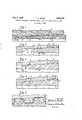
- Figure 1is a longitudinal section of a fully made-up casing pipe joint embodying the principles of the invention with only half of the joint being shown and the 'rest being broken away;
- Fig. 3is a view similar to that of Fig. 2 showing the surface contact generated between the conical sealing surfaces of the coupling members after normal make-up;
- Fig. 4is a view similar to that of Fig. 2 showing the coupling members after full make-up with the pin member engaging the internal shoulder of the box member;
- Fig. 5is an enlarged fragmentary section showing certain details of threadconstruction.
- the box and pin members 1 and 2are provided with complementary internal and external threaded portions 3 and 4, respectively, which are disposed along a relatively steep uniformly tapered thread pitch cone indicated by the dot-dash line 5 as shown in Fig. 5.
- the threaded portion 4 on the pin member 2is spaced axially outwardly from the inner end of the pin so that in coupled relation an unthreaded portion of the pin member will extend well into the box member 1, as will be explained hereinafter.
- the front flanks 12move out of contact so that if these surfaces are damaged during stabbing it will have no effect on the make-up of the joint.
- the rear flanks 13 of the respective threads 8 and 9are also disposed at a relatively steep angle, again about six degrees from radial.
- the thread designprovides that the rear flanks 13 are drawn together upon threading. By providing steep flank angles the radial component tending to expand the box member 1 and.
- the thread designfurther provides that the crests 10 of thread 8 bottoms against roots 11 of thread 9 with clearance being provided between the crests 10 of thread 9 and roots 11 of thread 8. These clearances between thread height and thread width of the mating threads 8 and 9 provides some latitude in manufacturing tolerances tending to minimize machining costs.
Landscapes
- Engineering & Computer Science (AREA)
- Mechanical Engineering (AREA)
- Life Sciences & Earth Sciences (AREA)
- Geology (AREA)
- Mining & Mineral Resources (AREA)
- General Engineering & Computer Science (AREA)
- Physics & Mathematics (AREA)
- Environmental & Geological Engineering (AREA)
- Fluid Mechanics (AREA)
- General Life Sciences & Earth Sciences (AREA)
- Geochemistry & Mineralogy (AREA)
- Non-Disconnectible Joints And Screw-Threaded Joints (AREA)
Description
July 7, 1959 T. L. BLOSE 2,893,759
CONICALLY TAPERED SCREW-TYPE CASING JOINT WITH METAL T0METAL/S EAL F iled May 6, 1957 l8 I9 23 if 4 v Fig. 2 r Ii Q W? k /8Q f 23/// v Fig-,5
m? 6 I, 5 INVENTOR. I W 1 THOMAS L. BLUSE 1, ',1 BY I I7 M 2,893,759 Ice Patented July 7, 1959 CONICALLY TAPERED SCREW-TYPE CASING JOINT WITH METAL-TO-METAL SEAL 1 Claim. (Cl. 285-334) This invention relates to certain improvements in casing joints. 7
The search for oil and gas reserves has brought about the exploration of ever deeper formations. These deeper formations require longer strings of easing pipe and are producing both oil and gas at extremely high pressures. Thisincreased length of casing strings imposes the upper portion of the string to very high tensile loads and the higher pressures from the deeper formations also exposes the upper portion of the string to high internal pressures where there is little or no offsetting external pressure on the casing. With standard joints there are limitations to the depths to which a string of casing can run. Merely increasing the wall thickness of the casing having a standard joint to carry the higher tensile loads is to a great extent self-defeating in view of the increased load weight imposed on the string. Thus, it is imperative that the casing joints be improved and made more efiicient to withstand the high pressures and tensile loads. This invention is directed to such improved joints for casing pipe and since the joints of the casing would be the same throughout, only one joint need be described.
The casing joint of this invention includes a female or box member and a mating male or pin member which are coupled together. The box member is provided with an internally threaded portion adjacent the end thereof while the pin member is provided with a complementary externally threaded portion spaced axially inwardly from the end thereof. The box member is provided with a conical sealing surface which extends axially inwardly from the threaded portion and the pin member is likewise provided with a conical sealing surface which extends from the threaded portion thereof axially inwardly toward the end of the pin member. The sealingsurface of the pin is provided with a faster taper than that of the box sealing surface so that upon joint makeup a line contact is initially established between the sealing surfaces and upon further make-up at least one of the members is deformed radially to generate a surface contact between the sealing surfaces. The structure of this invention provides a high strength, leak-resistant joint which is better adapted to withstand the high pressures and tensile loads encountered in the exploration of deep formations.
The drawing furnished herewith illustrates the best mode of carrying out the invention as presently contemplated and set forth hereinafter.
In the drawing:
Figure 1 is a longitudinal section of a fully made-up casing pipe joint embodying the principles of the invention with only half of the joint being shown and the 'rest being broken away;
Fig. 2 is an enlarged fragmentary longitudinal section of the partially made-up joint showing the initial line contact established between the conical sealing surfaces of the coupling members;
Fig. 3 is a view similar to that of Fig. 2 showing the surface contact generated between the conical sealing surfaces of the coupling members after normal make-up;
Fig. 4 is a view similar to that of Fig. 2 showing the coupling members after full make-up with the pin member engaging the internal shoulder of the box member; and
Fig. 5 is an enlarged fragmentary section showing certain details of threadconstruction.
Referring to the drawing, the casing joint comprises a cylindrical female or box member 1 coupled with a cylindrical male orpin member 2. Themembers 1 and 2 may be formed integrally on the ends of adjacent casing members, not shown, for coupling the casing members directly together, or one of the casing joint members may be formed integrally on a double ended coupling element, not shown, where a coupling element is disposed between adjacent lengths of easing pipe.
The box andpin members 1 and 2 are provided with complementary internal and external threadedportions 3 and 4, respectively, which are disposed along a relatively steep uniformly tapered thread pitch cone indicated by the dot-dash line 5 as shown in Fig. 5. The threadedportion 4 on thepin member 2 is spaced axially outwardly from the inner end of the pin so that in coupled relation an unthreaded portion of the pin member will extend well into the box member 1, as will be explained hereinafter.
The thread root cones, shown by dot-dash lines 6 and 7 in Fig. 5 for the threadedportions 3 and 4, respectively, parallel the pitch cone 5 and are spaced substantially equidistant therefrom.
The threads 8 of threaded portion 3 of box member 1 and threads 9 of threadedportions 4 ofpin 2 are of a rugged modified acme type capable of withstanding considerable abuse in handling and makeup. The crests 10 and roots 11 of threads 8 and 9 parallel the axis of the joint. The forward flanks 12 of threads 8 and 9, respectively, are disposed at a relatively steep angle with about six degrees from radial being preferred. Planks 12 make contact first upon make-up and frequently with a jolt and their near radial surfaces prevent wedging effects from heavy stabbing. Upon further make-up of the joint and as shown particularly in Fig. 5, the front flanks 12 move out of contact so that if these surfaces are damaged during stabbing it will have no effect on the make-up of the joint. As further shown in- Fig. 5, the rear flanks 13 of the respective threads 8 and 9 are also disposed at a relatively steep angle, again about six degrees from radial. The thread design provides that the rear flanks 13 are drawn together upon threading. By providing steep flank angles the radial component tending to expand the box member 1 and.
compress thepin member 2 due to the tensile load of the casing length on the joint is minimized, thereby minimizing the cause for thread jump outs. The thread design further provides that the crests 10 of thread 8 bottoms against roots 11 of thread 9 with clearance being provided between the crests 10 of thread 9 and roots 11 of thread 8. These clearances between thread height and thread width of the mating threads 8 and 9 provides some latitude in manufacturing tolerances tending to minimize machining costs.
To further increase the joint strength in tension, the thread roots 11 ofpin member 2 run out to the full outside diameter of the member. Thus, thread engagement betweenmembers 1 and 2 is maximized and the tensile load transmitted through the fully made-up joint is carried by the greatest cross-sectional area of the pipe to minimize the unit stress therein.
The box member 1 is also provided with a relatively longconical sealing surface 14 substantially complementary to acorresponding sealing surface 15 on pin menu
Priority Applications (1)
| Application Number | Priority Date | Filing Date | Title |
|---|---|---|---|
| US657187AUS2893759A (en) | 1957-05-06 | 1957-05-06 | Conically tapered screw-type casing joint with metal-to-metal seal |
Applications Claiming Priority (1)
| Application Number | Priority Date | Filing Date | Title |
|---|---|---|---|
| US657187AUS2893759A (en) | 1957-05-06 | 1957-05-06 | Conically tapered screw-type casing joint with metal-to-metal seal |
Publications (1)
| Publication Number | Publication Date |
|---|---|
| US2893759Atrue US2893759A (en) | 1959-07-07 |
Family
ID=24636185
Family Applications (1)
| Application Number | Title | Priority Date | Filing Date |
|---|---|---|---|
| US657187AExpired - LifetimeUS2893759A (en) | 1957-05-06 | 1957-05-06 | Conically tapered screw-type casing joint with metal-to-metal seal |
Country Status (1)
| Country | Link |
|---|---|
| US (1) | US2893759A (en) |
Cited By (52)
| Publication number | Priority date | Publication date | Assignee | Title |
|---|---|---|---|---|
| US3224799A (en)* | 1962-06-26 | 1965-12-21 | Armco Steel Corp | Threaded tube joint having a metal-to-metal seal |
| DE2330872A1 (en)* | 1972-06-16 | 1974-01-03 | Vallourec Lorraine Escaut | PIPE CONNECTION |
| FR2190238A5 (en)* | 1972-06-16 | 1974-01-25 | Vallourec | |
| US3870351A (en)* | 1972-03-31 | 1975-03-11 | Sumitomo Metal Ind | Threaded tube joint structure for casing, particularly oil well tubing |
| US4244521A (en)* | 1978-04-01 | 1981-01-13 | Bochumer Eisenhuette Heintzmann Gmbh & Co. | Arrangement for discharging liquid medium under high pressure |
| USRE30647E (en)* | 1975-04-23 | 1981-06-16 | Hydril Company | Tubular connection |
| US4373754A (en)* | 1978-08-09 | 1983-02-15 | Hydril Company | Threaded connector |
| US4377302A (en)* | 1981-05-14 | 1983-03-22 | Nippon Steel Corporation | Threaded joint with high gas-leak-tightness for oil and gas well pipe |
| US4384737A (en)* | 1980-04-25 | 1983-05-24 | Republic Steel Corporation | Threaded joint for well casing and tubing |
| US4398756A (en)* | 1980-09-15 | 1983-08-16 | Vallourec, S. A. | Cylindro-conical pipe joint |
| EP0104720A1 (en)* | 1982-09-20 | 1984-04-04 | Lone Star Steel Company | Tubular connection |
| WO1984002948A1 (en)* | 1983-01-17 | 1984-08-02 | Hydril Co | Tubular coupling with improved metal to metal seal |
| EP0108980A3 (en)* | 1982-11-15 | 1984-08-22 | Quanex Corporation | Tubular connection |
| WO1986001252A1 (en)* | 1984-08-13 | 1986-02-27 | Hydril Company | Well pipe joint |
| US4600224A (en)* | 1983-12-23 | 1986-07-15 | Interlock Technologies Corporation | Tubular connection having a chevron wedge thread |
| US4600225A (en)* | 1983-12-23 | 1986-07-15 | Interlock Technologies Corporation | Tubular connection having a parallel chevron thread |
| US4611838A (en)* | 1982-02-27 | 1986-09-16 | Mannesmann Aktiengesellschaft | Fluidtight pipe joint |
| US4736967A (en)* | 1986-12-04 | 1988-04-12 | The Hydril Company | Tubular pin configuration to prevent galling while ensuring sealing |
| US4817962A (en)* | 1987-12-28 | 1989-04-04 | The Hydril Company | Universal tubular connection having a variable metal-to-metal seal width corresponding to material yield strength |
| US4830411A (en)* | 1987-02-23 | 1989-05-16 | Nippon Steel Corporation | Threaded joint for oil-well pipe |
| US4871194A (en)* | 1986-05-02 | 1989-10-03 | Sumitomo Metal Industries, Ltd. | Oil well pipe joint and manufacturing method therefor |
| US5007665A (en)* | 1986-12-23 | 1991-04-16 | Cipriano Bovisio | Coupling for well casings |
| USRE34467E (en)* | 1983-04-29 | 1993-12-07 | The Hydril Company | Tubular connection |
| US5330239A (en)* | 1990-01-19 | 1994-07-19 | Ipsco Enterprises Inc. | Pipe coupling |
| US5348350A (en)* | 1980-01-19 | 1994-09-20 | Ipsco Enterprises Inc. | Pipe coupling |
| US5468029A (en)* | 1990-01-19 | 1995-11-21 | Ipsco Enterprises Inc. | Pipe coupling |
| US5498035A (en)* | 1990-01-19 | 1996-03-12 | Blose; Thomas L. | Pipe coupling |
| US5921591A (en)* | 1992-10-07 | 1999-07-13 | Argent; Michael E. | Pipe connecting assembly and method for joining two lengths of pipe by a press-fit connection |
| US5931511A (en)* | 1997-05-02 | 1999-08-03 | Grant Prideco, Inc. | Threaded connection for enhanced fatigue resistance |
| US6024646A (en)* | 1997-10-02 | 2000-02-15 | Ipsco Enterprises Inc. | Swaged pin end of pipe connection |
| US6322110B1 (en) | 1997-08-11 | 2001-11-27 | Marubeni Tubulars, Inc. | Tubular connection |
| US6554287B1 (en)* | 1999-12-09 | 2003-04-29 | Hydril Company | Collapsing type seal for expandable tubular connections |
| US6595557B2 (en)* | 2000-01-13 | 2003-07-22 | Hsc. S.A.L. | Screw-threaded pipe joint |
| US6705648B1 (en)* | 1997-12-04 | 2004-03-16 | Nippon Steel Corporation | Pipe joint |
| US20040113427A1 (en)* | 1999-12-03 | 2004-06-17 | Ernst Hugo A. | Assembly of hollow torque transmitting sucker rods and sealing nipple with improved seal and fluid flow |
| US6764108B2 (en) | 1999-12-03 | 2004-07-20 | Siderca S.A.I.C. | Assembly of hollow torque transmitting sucker rods |
| FR2855236A1 (en)* | 2003-05-22 | 2004-11-26 | Siderca Sa Ind & Com | Assembly with high fatigue resistance, e.g. for pump pistons made using conical thread with trapezoidal teeth meshing flank-to-flank |
| US20060071474A1 (en)* | 2004-09-28 | 2006-04-06 | Argus Machine Co., Ltd. | Threaded connection for drill pipes |
| US20060125234A1 (en)* | 2003-09-24 | 2006-06-15 | Siderca S.A.I.C. | Hollow sucker rod connection with second torque shoulder |
| US20060255591A1 (en)* | 2005-05-13 | 2006-11-16 | Reynolds Harris A Jr | Novel treating method and design method for tubular connections |
| US20080146470A1 (en)* | 2006-12-18 | 2008-06-19 | Zap-Lok Pipeline Systems, Inc. | Lubricating fast setting epoxy composition |
| US20080143101A1 (en)* | 2006-12-18 | 2008-06-19 | Logan Robert J | Subsea Mechanical Joint |
| US20080143104A1 (en)* | 2006-12-18 | 2008-06-19 | Logan Robert J | Subsea Piping System |
| US20090200798A1 (en)* | 2006-03-31 | 2009-08-13 | Takahiro Hamamoto | Tubular threaded joint |
| US20110025051A1 (en)* | 2007-11-08 | 2011-02-03 | Suguru Yamaguchi | Threaded joint for steel pipes |
| US20120013123A1 (en)* | 2009-03-26 | 2012-01-19 | Sandvik Intellectual Property Ab | Threaded thin-walled drill tube joint |
| CN102587843A (en)* | 2012-03-27 | 2012-07-18 | 无锡西姆莱斯石油专用管制造有限公司 | Special round thread highly-torque-resistant oil casing coupling |
| CN102587842A (en)* | 2012-03-27 | 2012-07-18 | 无锡西姆莱斯石油专用管制造有限公司 | Special round thread highly-torque-resistant pipe coupling |
| CN102606086A (en)* | 2012-03-27 | 2012-07-25 | 无锡西姆莱斯石油专用管制造有限公司 | Connecting joint with special knuckle threads for oil casing |
| US9677346B2 (en) | 2012-11-28 | 2017-06-13 | Ultra Premium Oilfield Services, Ltd. | Tubular connection with helically extending torque shoulder |
| US9869139B2 (en) | 2012-11-28 | 2018-01-16 | Ultra Premium Oilfield Services, Ltd. | Tubular connection with helically extending torque shoulder |
| US10619778B2 (en) | 2016-05-06 | 2020-04-14 | Northwest Pipe Company | Pipe ram joint |
Citations (5)
| Publication number | Priority date | Publication date | Assignee | Title |
|---|---|---|---|---|
| US816155A (en)* | 1903-12-14 | 1906-03-27 | Mark Dean | Joint for pipes. |
| US2006520A (en)* | 1933-07-17 | 1935-07-02 | Hydril Co | Casing joint |
| US2062407A (en)* | 1935-02-19 | 1936-12-01 | Spang Chalfant & Company Inc | Joint |
| GB539139A (en)* | 1940-09-23 | 1941-08-28 | James Cuthill | Improvements in fluid pressure joints for pipes and other conduits, fittings and the like |
| US2671949A (en)* | 1948-11-23 | 1954-03-16 | Chicago Pneumatic Tool Co | Method of making tool joints |
- 1957
- 1957-05-06USUS657187Apatent/US2893759A/ennot_activeExpired - Lifetime
Patent Citations (5)
| Publication number | Priority date | Publication date | Assignee | Title |
|---|---|---|---|---|
| US816155A (en)* | 1903-12-14 | 1906-03-27 | Mark Dean | Joint for pipes. |
| US2006520A (en)* | 1933-07-17 | 1935-07-02 | Hydril Co | Casing joint |
| US2062407A (en)* | 1935-02-19 | 1936-12-01 | Spang Chalfant & Company Inc | Joint |
| GB539139A (en)* | 1940-09-23 | 1941-08-28 | James Cuthill | Improvements in fluid pressure joints for pipes and other conduits, fittings and the like |
| US2671949A (en)* | 1948-11-23 | 1954-03-16 | Chicago Pneumatic Tool Co | Method of making tool joints |
Cited By (61)
| Publication number | Priority date | Publication date | Assignee | Title |
|---|---|---|---|---|
| US3224799A (en)* | 1962-06-26 | 1965-12-21 | Armco Steel Corp | Threaded tube joint having a metal-to-metal seal |
| US3870351A (en)* | 1972-03-31 | 1975-03-11 | Sumitomo Metal Ind | Threaded tube joint structure for casing, particularly oil well tubing |
| DE2330872A1 (en)* | 1972-06-16 | 1974-01-03 | Vallourec Lorraine Escaut | PIPE CONNECTION |
| FR2190238A5 (en)* | 1972-06-16 | 1974-01-25 | Vallourec | |
| FR2190237A5 (en)* | 1972-06-16 | 1974-01-25 | Vallourec | |
| USRE30647E (en)* | 1975-04-23 | 1981-06-16 | Hydril Company | Tubular connection |
| US4244521A (en)* | 1978-04-01 | 1981-01-13 | Bochumer Eisenhuette Heintzmann Gmbh & Co. | Arrangement for discharging liquid medium under high pressure |
| US4373754A (en)* | 1978-08-09 | 1983-02-15 | Hydril Company | Threaded connector |
| US5348350A (en)* | 1980-01-19 | 1994-09-20 | Ipsco Enterprises Inc. | Pipe coupling |
| US4384737A (en)* | 1980-04-25 | 1983-05-24 | Republic Steel Corporation | Threaded joint for well casing and tubing |
| US4398756A (en)* | 1980-09-15 | 1983-08-16 | Vallourec, S. A. | Cylindro-conical pipe joint |
| US4377302A (en)* | 1981-05-14 | 1983-03-22 | Nippon Steel Corporation | Threaded joint with high gas-leak-tightness for oil and gas well pipe |
| US4611838A (en)* | 1982-02-27 | 1986-09-16 | Mannesmann Aktiengesellschaft | Fluidtight pipe joint |
| EP0104720A1 (en)* | 1982-09-20 | 1984-04-04 | Lone Star Steel Company | Tubular connection |
| EP0108980A3 (en)* | 1982-11-15 | 1984-08-22 | Quanex Corporation | Tubular connection |
| WO1984002948A1 (en)* | 1983-01-17 | 1984-08-02 | Hydril Co | Tubular coupling with improved metal to metal seal |
| US5423579A (en)* | 1983-01-17 | 1995-06-13 | Hydril Company | Tubular coupling with metal to metal seal |
| USRE34467E (en)* | 1983-04-29 | 1993-12-07 | The Hydril Company | Tubular connection |
| US4600224A (en)* | 1983-12-23 | 1986-07-15 | Interlock Technologies Corporation | Tubular connection having a chevron wedge thread |
| US4600225A (en)* | 1983-12-23 | 1986-07-15 | Interlock Technologies Corporation | Tubular connection having a parallel chevron thread |
| WO1986001252A1 (en)* | 1984-08-13 | 1986-02-27 | Hydril Company | Well pipe joint |
| US4871194A (en)* | 1986-05-02 | 1989-10-03 | Sumitomo Metal Industries, Ltd. | Oil well pipe joint and manufacturing method therefor |
| US4736967A (en)* | 1986-12-04 | 1988-04-12 | The Hydril Company | Tubular pin configuration to prevent galling while ensuring sealing |
| US5007665A (en)* | 1986-12-23 | 1991-04-16 | Cipriano Bovisio | Coupling for well casings |
| US4830411A (en)* | 1987-02-23 | 1989-05-16 | Nippon Steel Corporation | Threaded joint for oil-well pipe |
| US4817962A (en)* | 1987-12-28 | 1989-04-04 | The Hydril Company | Universal tubular connection having a variable metal-to-metal seal width corresponding to material yield strength |
| US5330239A (en)* | 1990-01-19 | 1994-07-19 | Ipsco Enterprises Inc. | Pipe coupling |
| US5468029A (en)* | 1990-01-19 | 1995-11-21 | Ipsco Enterprises Inc. | Pipe coupling |
| US5498035A (en)* | 1990-01-19 | 1996-03-12 | Blose; Thomas L. | Pipe coupling |
| US5921591A (en)* | 1992-10-07 | 1999-07-13 | Argent; Michael E. | Pipe connecting assembly and method for joining two lengths of pipe by a press-fit connection |
| US5931511A (en)* | 1997-05-02 | 1999-08-03 | Grant Prideco, Inc. | Threaded connection for enhanced fatigue resistance |
| US6322110B1 (en) | 1997-08-11 | 2001-11-27 | Marubeni Tubulars, Inc. | Tubular connection |
| US6024646A (en)* | 1997-10-02 | 2000-02-15 | Ipsco Enterprises Inc. | Swaged pin end of pipe connection |
| US6705648B1 (en)* | 1997-12-04 | 2004-03-16 | Nippon Steel Corporation | Pipe joint |
| US6991267B2 (en) | 1999-12-03 | 2006-01-31 | Siderca S.A.I.C. | Assembly of hollow torque transmitting sucker rods and sealing nipple with improved seal and fluid flow |
| US20040113427A1 (en)* | 1999-12-03 | 2004-06-17 | Ernst Hugo A. | Assembly of hollow torque transmitting sucker rods and sealing nipple with improved seal and fluid flow |
| US6764108B2 (en) | 1999-12-03 | 2004-07-20 | Siderca S.A.I.C. | Assembly of hollow torque transmitting sucker rods |
| US6554287B1 (en)* | 1999-12-09 | 2003-04-29 | Hydril Company | Collapsing type seal for expandable tubular connections |
| US6595557B2 (en)* | 2000-01-13 | 2003-07-22 | Hsc. S.A.L. | Screw-threaded pipe joint |
| FR2855236A1 (en)* | 2003-05-22 | 2004-11-26 | Siderca Sa Ind & Com | Assembly with high fatigue resistance, e.g. for pump pistons made using conical thread with trapezoidal teeth meshing flank-to-flank |
| US20060125234A1 (en)* | 2003-09-24 | 2006-06-15 | Siderca S.A.I.C. | Hollow sucker rod connection with second torque shoulder |
| US7431347B2 (en) | 2003-09-24 | 2008-10-07 | Siderca S.A.I.C. | Hollow sucker rod connection with second torque shoulder |
| US20060071474A1 (en)* | 2004-09-28 | 2006-04-06 | Argus Machine Co., Ltd. | Threaded connection for drill pipes |
| US20060255591A1 (en)* | 2005-05-13 | 2006-11-16 | Reynolds Harris A Jr | Novel treating method and design method for tubular connections |
| WO2006124385A1 (en) | 2005-05-13 | 2006-11-23 | Hydril Llc | Novel treating method and design method for tubular connections |
| US7497481B2 (en) | 2005-05-13 | 2009-03-03 | Hydril Llc | Treating method and design method for tubular connections |
| US7823931B2 (en)* | 2006-03-31 | 2010-11-02 | Sumitomo Metal Industries, Ltd. | Tubular threaded joint |
| US20090200798A1 (en)* | 2006-03-31 | 2009-08-13 | Takahiro Hamamoto | Tubular threaded joint |
| US20080143101A1 (en)* | 2006-12-18 | 2008-06-19 | Logan Robert J | Subsea Mechanical Joint |
| US20080143104A1 (en)* | 2006-12-18 | 2008-06-19 | Logan Robert J | Subsea Piping System |
| US20080146470A1 (en)* | 2006-12-18 | 2008-06-19 | Zap-Lok Pipeline Systems, Inc. | Lubricating fast setting epoxy composition |
| US20110025051A1 (en)* | 2007-11-08 | 2011-02-03 | Suguru Yamaguchi | Threaded joint for steel pipes |
| US9568125B2 (en)* | 2007-11-08 | 2017-02-14 | Nippon Steel & Sumitomo Metal Corporation | Threaded joint for steel pipes |
| US20120013123A1 (en)* | 2009-03-26 | 2012-01-19 | Sandvik Intellectual Property Ab | Threaded thin-walled drill tube joint |
| US8919824B2 (en)* | 2009-03-26 | 2014-12-30 | Sandvik Intellectual Property Ab | Threaded thin-walled drill tube joint |
| CN102587843A (en)* | 2012-03-27 | 2012-07-18 | 无锡西姆莱斯石油专用管制造有限公司 | Special round thread highly-torque-resistant oil casing coupling |
| CN102587842A (en)* | 2012-03-27 | 2012-07-18 | 无锡西姆莱斯石油专用管制造有限公司 | Special round thread highly-torque-resistant pipe coupling |
| CN102606086A (en)* | 2012-03-27 | 2012-07-25 | 无锡西姆莱斯石油专用管制造有限公司 | Connecting joint with special knuckle threads for oil casing |
| US9677346B2 (en) | 2012-11-28 | 2017-06-13 | Ultra Premium Oilfield Services, Ltd. | Tubular connection with helically extending torque shoulder |
| US9869139B2 (en) | 2012-11-28 | 2018-01-16 | Ultra Premium Oilfield Services, Ltd. | Tubular connection with helically extending torque shoulder |
| US10619778B2 (en) | 2016-05-06 | 2020-04-14 | Northwest Pipe Company | Pipe ram joint |
Similar Documents
| Publication | Publication Date | Title |
|---|---|---|
| US2893759A (en) | Conically tapered screw-type casing joint with metal-to-metal seal | |
| US3224799A (en) | Threaded tube joint having a metal-to-metal seal | |
| AU2011295130B2 (en) | Tubular threaded connection | |
| EP0767335B1 (en) | Threaded joint for tubes | |
| US2772102A (en) | Sealed threaded pipe joint | |
| US4521042A (en) | Threaded connection | |
| EP1514046B1 (en) | Threaded pipe joint | |
| US4600225A (en) | Tubular connection having a parallel chevron thread | |
| US4373754A (en) | Threaded connector | |
| US3047316A (en) | Packed pin and box drill pipe coupling with means preventing extrusion of packing ring | |
| US5092635A (en) | Buttress thread form | |
| US4600224A (en) | Tubular connection having a chevron wedge thread | |
| US8678448B2 (en) | Threaded connection | |
| CA2338956C (en) | Threaded and coupled connection for improved fatigue resistance | |
| US8931809B2 (en) | Tubular threaded connection | |
| US6581980B1 (en) | Threaded connection with high compressive rating | |
| US7475476B2 (en) | Method for producing a threaded tubular connection sealed to the outside | |
| EP0197050B1 (en) | Metal-to-metal wedge thread coupling connector | |
| US20090250927A1 (en) | Threaded Pipe Connector | |
| EP3622209B1 (en) | Curvilinear sealing system | |
| US3494640A (en) | Friction-type joint with stress concentration relief | |
| JP5538418B2 (en) | Screw connection for oil field | |
| CN108625797A (en) | A kind of hermetic sealing drill pipe joint preventing reversion shackle | |
| OA17366A (en) | Tubular threaded connection. |