US20230081019A1 - Vacuum pump - Google Patents
Vacuum pumpDownload PDFInfo
- Publication number
- US20230081019A1 US20230081019A1US17/943,328US202217943328AUS2023081019A1US 20230081019 A1US20230081019 A1US 20230081019A1US 202217943328 AUS202217943328 AUS 202217943328AUS 2023081019 A1US2023081019 A1US 2023081019A1
- Authority
- US
- United States
- Prior art keywords
- valve
- ball
- pump
- fluid pathway
- vacuum pump
- Prior art date
- Legal status (The legal status is an assumption and is not a legal conclusion. Google has not performed a legal analysis and makes no representation as to the accuracy of the status listed.)
- Pending
Links
Images


Classifications
- F—MECHANICAL ENGINEERING; LIGHTING; HEATING; WEAPONS; BLASTING
- F04—POSITIVE - DISPLACEMENT MACHINES FOR LIQUIDS; PUMPS FOR LIQUIDS OR ELASTIC FLUIDS
- F04B—POSITIVE-DISPLACEMENT MACHINES FOR LIQUIDS; PUMPS
- F04B35/00—Piston pumps specially adapted for elastic fluids and characterised by the driving means to their working members, or by combination with, or adaptation to, specific driving engines or motors, not otherwise provided for
- F04B35/04—Piston pumps specially adapted for elastic fluids and characterised by the driving means to their working members, or by combination with, or adaptation to, specific driving engines or motors, not otherwise provided for the means being electric
- F—MECHANICAL ENGINEERING; LIGHTING; HEATING; WEAPONS; BLASTING
- F04—POSITIVE - DISPLACEMENT MACHINES FOR LIQUIDS; PUMPS FOR LIQUIDS OR ELASTIC FLUIDS
- F04B—POSITIVE-DISPLACEMENT MACHINES FOR LIQUIDS; PUMPS
- F04B37/00—Pumps having pertinent characteristics not provided for in, or of interest apart from, groups F04B25/00 - F04B35/00
- F04B37/10—Pumps having pertinent characteristics not provided for in, or of interest apart from, groups F04B25/00 - F04B35/00 for special use
- F04B37/14—Pumps having pertinent characteristics not provided for in, or of interest apart from, groups F04B25/00 - F04B35/00 for special use to obtain high vacuum
- F—MECHANICAL ENGINEERING; LIGHTING; HEATING; WEAPONS; BLASTING
- F04—POSITIVE - DISPLACEMENT MACHINES FOR LIQUIDS; PUMPS FOR LIQUIDS OR ELASTIC FLUIDS
- F04B—POSITIVE-DISPLACEMENT MACHINES FOR LIQUIDS; PUMPS
- F04B39/00—Component parts, details, or accessories, of pumps or pumping systems specially adapted for elastic fluids, not otherwise provided for in, or of interest apart from, groups F04B25/00 - F04B37/00
- F04B39/08—Actuation of distribution members
- F—MECHANICAL ENGINEERING; LIGHTING; HEATING; WEAPONS; BLASTING
- F04—POSITIVE - DISPLACEMENT MACHINES FOR LIQUIDS; PUMPS FOR LIQUIDS OR ELASTIC FLUIDS
- F04B—POSITIVE-DISPLACEMENT MACHINES FOR LIQUIDS; PUMPS
- F04B39/00—Component parts, details, or accessories, of pumps or pumping systems specially adapted for elastic fluids, not otherwise provided for in, or of interest apart from, groups F04B25/00 - F04B37/00
- F04B39/10—Adaptations or arrangements of distribution members
- F04B39/1006—Adaptations or arrangements of distribution members the members being ball valves
- F—MECHANICAL ENGINEERING; LIGHTING; HEATING; WEAPONS; BLASTING
- F04—POSITIVE - DISPLACEMENT MACHINES FOR LIQUIDS; PUMPS FOR LIQUIDS OR ELASTIC FLUIDS
- F04B—POSITIVE-DISPLACEMENT MACHINES FOR LIQUIDS; PUMPS
- F04B53/00—Component parts, details or accessories not provided for in, or of interest apart from, groups F04B1/00 - F04B23/00 or F04B39/00 - F04B47/00
- F04B53/10—Valves; Arrangement of valves
- F04B53/1002—Ball valves
- F04B53/1005—Ball valves being formed by two closure members working in series
- F—MECHANICAL ENGINEERING; LIGHTING; HEATING; WEAPONS; BLASTING
- F04—POSITIVE - DISPLACEMENT MACHINES FOR LIQUIDS; PUMPS FOR LIQUIDS OR ELASTIC FLUIDS
- F04C—ROTARY-PISTON, OR OSCILLATING-PISTON, POSITIVE-DISPLACEMENT MACHINES FOR LIQUIDS; ROTARY-PISTON, OR OSCILLATING-PISTON, POSITIVE-DISPLACEMENT PUMPS
- F04C25/00—Adaptations of pumps for special use of pumps for elastic fluids
- F04C25/02—Adaptations of pumps for special use of pumps for elastic fluids for producing high vacuum
- F—MECHANICAL ENGINEERING; LIGHTING; HEATING; WEAPONS; BLASTING
- F04—POSITIVE - DISPLACEMENT MACHINES FOR LIQUIDS; PUMPS FOR LIQUIDS OR ELASTIC FLUIDS
- F04C—ROTARY-PISTON, OR OSCILLATING-PISTON, POSITIVE-DISPLACEMENT MACHINES FOR LIQUIDS; ROTARY-PISTON, OR OSCILLATING-PISTON, POSITIVE-DISPLACEMENT PUMPS
- F04C29/00—Component parts, details or accessories of pumps or pumping installations, not provided for in groups F04C18/00 - F04C28/00
- F04C29/12—Arrangements for admission or discharge of the working fluid, e.g. constructional features of the inlet or outlet
- F04C29/124—Arrangements for admission or discharge of the working fluid, e.g. constructional features of the inlet or outlet with inlet and outlet valves specially adapted for rotary or oscillating piston pumps
- F04C29/126—Arrangements for admission or discharge of the working fluid, e.g. constructional features of the inlet or outlet with inlet and outlet valves specially adapted for rotary or oscillating piston pumps of the non-return type
- F—MECHANICAL ENGINEERING; LIGHTING; HEATING; WEAPONS; BLASTING
- F16—ENGINEERING ELEMENTS AND UNITS; GENERAL MEASURES FOR PRODUCING AND MAINTAINING EFFECTIVE FUNCTIONING OF MACHINES OR INSTALLATIONS; THERMAL INSULATION IN GENERAL
- F16K—VALVES; TAPS; COCKS; ACTUATING-FLOATS; DEVICES FOR VENTING OR AERATING
- F16K15/00—Check valves
- F16K15/02—Check valves with guided rigid valve members
- F16K15/04—Check valves with guided rigid valve members shaped as balls
- F16K15/042—Check valves with guided rigid valve members shaped as balls with a plurality of balls
- F—MECHANICAL ENGINEERING; LIGHTING; HEATING; WEAPONS; BLASTING
- F16—ENGINEERING ELEMENTS AND UNITS; GENERAL MEASURES FOR PRODUCING AND MAINTAINING EFFECTIVE FUNCTIONING OF MACHINES OR INSTALLATIONS; THERMAL INSULATION IN GENERAL
- F16K—VALVES; TAPS; COCKS; ACTUATING-FLOATS; DEVICES FOR VENTING OR AERATING
- F16K15/00—Check valves
- F16K15/18—Check valves with actuating mechanism; Combined check valves and actuated valves
- F16K15/182—Check valves with actuating mechanism; Combined check valves and actuated valves with actuating mechanism
- F16K15/1823—Check valves with actuating mechanism; Combined check valves and actuated valves with actuating mechanism for ball check valves
- F—MECHANICAL ENGINEERING; LIGHTING; HEATING; WEAPONS; BLASTING
- F16—ENGINEERING ELEMENTS AND UNITS; GENERAL MEASURES FOR PRODUCING AND MAINTAINING EFFECTIVE FUNCTIONING OF MACHINES OR INSTALLATIONS; THERMAL INSULATION IN GENERAL
- F16K—VALVES; TAPS; COCKS; ACTUATING-FLOATS; DEVICES FOR VENTING OR AERATING
- F16K15/00—Check valves
- F16K15/18—Check valves with actuating mechanism; Combined check valves and actuated valves
- F16K15/184—Combined check valves and actuated valves
- F16K15/1843—Combined check valves and actuated valves for ball check valves
- F—MECHANICAL ENGINEERING; LIGHTING; HEATING; WEAPONS; BLASTING
- F16—ENGINEERING ELEMENTS AND UNITS; GENERAL MEASURES FOR PRODUCING AND MAINTAINING EFFECTIVE FUNCTIONING OF MACHINES OR INSTALLATIONS; THERMAL INSULATION IN GENERAL
- F16K—VALVES; TAPS; COCKS; ACTUATING-FLOATS; DEVICES FOR VENTING OR AERATING
- F16K2200/00—Details of valves
- F16K2200/20—Common housing having a single inlet, a single outlet and multiple valve members
- F16K2200/201—Common housing having a single inlet, a single outlet and multiple valve members of diverse type, size or shape
Definitions
- the present inventionrelates to pumps, and more particularly to recovery and vacuum pumps for refrigeration and air-conditioning systems.
- Vacuum pumpsare typically used to remove atmospheric air and any entrained water vapor from an HVAC system (e.g., a refrigeration or air conditioning circuit) prior to a refrigerant being returned after any maintenance has been performed.
- HVAC systeme.g., a refrigeration or air conditioning circuit
- a vacuum pumpincluding a motor, a pump coupled to the motor to receive torque therefrom, a trestle including an inlet port, an outlet port, and a fluid pathway therebetween the outlet port being fluidly connected to an inlet of the pump, a first valve positioned within the fluid pathway and adjustable between an open state, in which an airflow induced by the pump is drawn through the inlet port, and a closed state, in which a reverse airflow through the inlet port is prevented, and a second valve positioned within the fluid pathway in series with the first valve.
- the second valveis adjustable between an open state, in which the airflow induced by the pump is drawn through the inlet port, and a closed state, in which the reverse airflow through the inlet port is prevented when the motor is deactivated.
- the inventionprovides, in another aspect, a vacuum pump including a motor, a pump coupled to the motor to receive torque therefrom, a trestle including an inlet port, an outlet port, and a fluid pathway therebetween, the outlet port being fluidly connected to the pump, a first valve positioned within the fluid pathway and including a ball and a shaft coupled to the ball, and a second valve positioned within the fluid pathway in series with the first valve. Rotation of the shaft rotates the ball to adjust the first valve between an open state, in which an airflow induced by the pump is drawn through the inlet port, and a closed state, in which a reverse airflow through the inlet port is prevented when the motor is deactivated.
- a vacuum pumpincluding a motor, a pump coupled to the motor to receive torque therefrom, a trestle including an inlet port, an outlet port, and a fluid pathway therebetween, the outlet port being fluidly connected to the pump, a first valve positioned within the fluid pathway and adjustable between an open state, in which an airflow induced by the pump is drawn through the inlet port, and a closed state, in which a reverse airflow through the inlet port is prevented, and a second valve positioned within the fluid pathway in series with the first valve, the second valve including a ball moveable along a plurality of ribs formed in the fluid pathway to adjust the second valve between an open state, in which an airflow induced by the pump is drawn through the inlet port, and a closed state, in which a reverse airflow through the inlet port is prevented when the motor is deactivated.
- FIG. 1is a schematic view of a recovery pump and a vacuum pump in accordance with an embodiment of the invention, illustrating the recovery pump and the vacuum pump in fluid communication with an HVAC system.
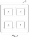
- FIG. 2is a schematic view of the vacuum pump of FIG. 1 .
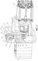
- FIG. 3is a perspective view of the vacuum pump of FIG. 1 .
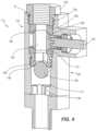
- FIG. 4is a cross-sectional view of a ball valve of the vacuum pump of FIG. 1 .
- FIG. 5is a cross-sectional view of a ball valve of a vacuum pump according to another embodiment of the invention.
- FIG. 6is a cross-sectional view of a check valve of a vacuum pump according to another embodiment of the invention.
- an HVAC system(e.g., refrigeration or air conditioning circuit 10 ) includes an evaporator 15 , a compressor 20 , a condenser 25 , and an expansion valve 30 .
- a refrigerantcirculates through the refrigeration circuit 10 , changing phases between liquid and vapor when passing through the evaporator 15 and the condenser 25 .
- the circuit 10schematically illustrates a typical vapor-compression refrigeration cycle commonly known by those of ordinary skill in the art. HVAC systems, such as the illustrated air conditioning circuit 10 , are commonly found in residential properties, commercial properties, vehicles, and many other systems.
- each component 15 , 20 , 25 , 30 and interconnecting conduit lines 17 , 22 , 27 , 32are first drained or emptied of any refrigerant with, for example, a recovery pump (not shown).
- the air conditioning circuit 10includes a port 35 to which the recovery pump and a vacuum pump 45 , which is used to remove atmospheric air and any entrained water vapor from the circuit 10 prior to the refrigerant being returned after any maintenance has been performed, may be coupled.
- the vacuum pump 45includes a motor 65 , a pump 70 driven by the motor 65 that is operable to draw suction, and an electronic control unit or controller 71 for controlling operation of the motor 65 .
- An inlet port 72 of the vacuum pump 45( FIG. 3 ) is coupled to the port 35 of the air conditioning circuit 10 to draw refrigerant from the air conditioning circuit 10 .
- the vacuum pump 45may be coupled to alternative circuits.
- the pump 70 of the illustrated embodimentis a rotary vane pump commonly known in the art.
- the motor 65is powered by an 18-volt lithium-ion battery pack 75 (FIG. 2 ).
- multiple battery packs 75may achieve a higher voltage (if used in series) or a higher capacity (if operating in parallel).
- the battery pack 75may include a different nominal voltage (e.g., 12 volts, 24 volts, etc.).
- the vacuum pump 45may include a power cord for connection to an external power source (e.g., AC power through a wall outlet).
- the illustrated motor 65is a brushless direct current (i.e., BLDC) motor. But, in other embodiments of the vacuum pump 45 , the motor 65 may be a brushed DC motor or an alternating current (i.e., AC) motor.
- the vacuum pump 45includes the inlet port 72 ( FIG. 1 ) for drawing atmospheric air from the circuit 10 and an outlet port 78 for discharging the air and water vapor to atmosphere.
- the controller 71activates the motor 65 (and therefore the pump 70 ) to draw a deep vacuum in the circuit 10 to remove air and any contaminants (e.g., water vapor, etc.) remaining in the circuit 10 .
- the air and contaminantsare drawn out through the port 35 , through the inlet port 72 of the vacuum pump 45 , and to the outlet port 78 .
- the air and contaminantsare then expelled into the environment.
- the air and contaminantsmay be stored in a tank.
- the vacuum pump 45further includes a trestle 100 positioned between the pump 70 and the motor 65 .
- the trestle 100is a hollow body defining a fluid pathway 102 that extends between the inlet port 72 , which is on the trestle 100 , and the pump 70 .
- the trestle 100also includes a trestle outlet 104 , which is fluidly connected with an inlet of the pump 70 .
- the trestle 100further includes a valve assembly 114 having an integrated ball valve 116 and a check valve 120 , which are located in series within the fluid pathway 102 between the inlet port 72 and the trestle outlet 104 .
- the ball valve 116is positioned downstream of the inlet port 72 in a direction of an airflow induced by the pump 70
- the check valve 120is positioned downstream of the ball valve 116 in the direction of the airflow induced by the pump 70 .
- the ball valve 116includes an inlet seat 108 , an outlet seat 112 spaced from the inlet seat 108 , and a ball 128 positioned between the inlet seat 108 and the outlet seat 112 ( FIG. 4 ).
- the ball 128is seated against each of the inlet seat 108 and the outlet seat 112 , thus forming a seal with each of the inlet seat 108 and the outlet seat 112 .
- the ball valve 116may also include a threaded fitting 122 for threading the ball valve 116 within the trestle 100 ( FIG. 3 ).
- the ball valve 116includes a manifold 129 having outer threads 130 that align with threads disposed proximate the inlet port 72 in the fluid pathway 102 .
- the threads 130seal the manifold with the inlet port 72 .
- the manifold 129abuts the inlet seat 108 such that the manifold 129 exerts a constant force onto the inlet seat 108 .
- FIG. 5illustrates a valve assembly 214 according to another embodiment of the disclosure.
- the valve assembly 214is similar to the valve assembly 114 described above and includes much of the same structure. And, the valve assembly 214 is disposed in the trestle 100 , as explained above. Features and elements that are similar to the features and elements of the valve assembly 114 are assigned the same reference numerals plus “100.” It should be understood that the features of the valve assembly 214 that are not explicitly described below have the same properties as the features of the valve assembly 114 .
- the valve assembly 214includes a spring 200 disposed between a manifold 229 and the inlet seat 208 such that the spring 200 pushes the inlet seat 208 away from the manifold 229 .
- the manifold 229is coupled to the inlet port 72 via fasteners 204 .
- the fasteners 204couple arms 206 of the manifold 229 onto an outer surface of the trestle 100 .
- An O-ring 210is disposed on an outer portion of the manifold 229 such that the manifold 229 is sealed with an inner surface 211 of a fluid pathway 202 .
- An O-ring 221is additionally disposed on the inlet seat 208 such that a seal is created between the inlet seat 208 and the inner surface 211 of the fluid pathway 202 .
- an O-ring 224may also be disposed on the outlet seat 212 to create a seal between the outlet seat 212 and the inner surface 211 of the fluid pathway 202 .
- the ball valve 116further includes a lever (not shown) and a shaft 132 coupled to the ball 128 , which includes a hole 134 therethrough.
- the hole 134passes through the ball 128 , permitting fluid flow through the ball 128 .
- the leveris pivotably coupled to the ball 128 via the shaft 132 , which transfers rotational motion to the ball 128 such that rotation of the lever also rotates the ball 128 .
- the ball 128 and shaft 132are rotatable between an open position, in which the hole 134 in the ball 128 is coaxially aligned with the fluid pathway 102 through the inlet seat 108 and the outlet seat 112 (coinciding with an open state of the ball valve 116 ), and a closed position, in which the hole 134 in the ball 128 is misaligned with the fluid pathway 102 through the inlet seat 108 and the outlet seat 112 (coinciding with a closed state of the ball valve 116 ).
- the open positionis 90 degrees from the closed position.
- the ball 128In the open position, the ball 128 permits flow through the fluid pathway 102 in the trestle 100 such that fluid may pass from the inlet port 72 , through the ball 128 , and to the trestle outlet 104 .
- the ball 128In the closed position, the ball 128 is rotated such that the hole 134 is misaligned with the fluid pathway 102 in the trestle 100 such that fluid is unable to pass through the ball valve 116 .
- the lever and shaft 132When the lever and shaft 132 are rotated to a position between the open position and the closed position, the ball 128 is rotated to a partially opened position such that a reduced volumetric flow rate of fluid can pass through the hole 134 relative to the (fully) open position. In other words, the flow of the fluid through the ball valve 116 decreases as the shaft 132 and ball 128 move from the open position to the closed position.
- the check valve 120is located within a vertically oriented section of the fluid pathway 102 within the trestle 100 .
- the check valve 120includes a ball 136 that is moveable within the fluid pathway 102 in the trestle 100 .
- the ball 136is movable between a closed position, in which the ball 136 abuts an internal seat 138 and an O-ring 139 within the fluid pathway 102 , and an open position in which the ball 136 is spaced from the internal seat 138 .
- the check valve 120includes ribs 140 formed in the fluid pathway 102 to support the ball 126 within the fluid pathway 102 when the ball is in the open position. When the ball 126 is in the closed position, the ball 126 is spaced from the ribs 140 .
- the check valve 120includes three ribs 140 disposed equidistant from each other on the surface of the fluid pathway 102 . In other embodiments, the check valve 120 may include greater or fewer than three ribs 140 . In yet other embodiments, the ribs 140 may not be equidistant from each other.
- the ribs 140prevent lateral movement of the ball 136 in the fluid pathway 102 and are positioned vertically along an inner surface 111 of the fluid pathway 102 , in a direction of the fluid flow, to create an annular gap or space between the ball 136 and the inner surface of the fluid pathway 102 .
- the spaceallows fluid to pass through the fluid pathway 102 , around the ball 136 .
- FIG. 6illustrates a valve assembly 314 according to another embodiment of the disclosure.
- the valve assembly 314is similar to the valve assembly 114 described above and includes much of the same structure. And, the valve assembly 314 is disposed in the trestle 100 , as explained above. Features and elements that are similar to the features and elements of the valve assembly 114 are assigned the same reference numerals plus “200.” It should be understood that the features of the valve assembly 314 that are not explicitly described below have the same properties as the features of the valve assembly 114 .
- the valve assembly 314includes a check valve 320 , which is located in series within a fluid pathway 302 between the inlet port 72 and the trestle outlet 104 .
- the check valve 320includes small ribs 300 disposed between the ribs 340 and the outlet seat 312 in the fluid pathway 302 to support a ball 336 within the fluid pathway 302 .
- the check valve 320includes three of the small ribs 300 disposed equidistant from each other on an inner surface 311 of the fluid pathway 302 .
- the check valve 320may include fewer than or more than three of the small ribs 300 .
- the small ribs 300may not be disposed equidistant from each other.
- the small ribs 300are integrally connected to the ribs 140 such that the small ribs 300 and the ribs 340 form a continuous rib.
- the small ribs 300define a radial width W 1 that is less than a radial width W 2 of the ribs 340 .
- Each of the ribs 340includes an angled section 304 that decreases a width of the rib 340 from the radial width W 2 to the radial width W 1 .
- the angled sections 304 of each rib 340together form a seat for supporting the ball 336 when the ball 336 is in an open position.
- the small ribs 300may be disconnected and separate from the ribs 340 .
- the check valve 320may not include the small ribs 300 .
- the ball 136 , 236 , 336is movable between the closed position, in which the ball 136 , 236 , 336 abuts the internal seat 138 , 238 , 338 and the O-ring 139 , 239 , 339 to prevent fluid flow through the pathway (coinciding with a closed state of the check valve 120 , 220 , 320 ), and the open position in which the ball 136 , 236 , 336 is spaced from the internal seat 138 , 238 , 338 and supported by the ribs 140 , 340 (coinciding with an open state of the check valve 120 , 220 , 320 ).
- the ball 136 , 236 , 336creates a seal with the internal seat 138 , 238 , 338 such that fluid is unable to pass through the fluid pathway 102 , 202 , 302 .
- the ball 136 , 236 , 336is supported by or held against the ribs 140 , 340 , spaced from the internal seat 138 , 238 , 338 in the fluid pathway 102 , 202 , 302 , such that the fluid can pass around the ball 136 , 236 , 336 .
- the pump 70is driven to induce the airflow through the inlet port 72 , the ball valve 116 , 216 , the check valve 120 , 230 , 320 , and the trestle outlet 104 in series.
- the induced airflow and/or the weight of the ball 136 , 236 , 336maintains the ball 136 , 236 , 336 in the open position against the ribs 140 , 340 and away from the internal seat 138 , 238 , 338 in the fluid pathway 102 , 202 , 302 .
- the usermay rotate the shaft 132 , 232 of the ball valve 116 , 216 to the closed position, thereby misaligning the hole 134 , 234 in the ball 128 , 228 from the fluid flow path 102 , 202 , 302 through the inlet seat 108 , 208 and outlet seat 112 , 212 .
- Thisforms a tighter seal between the inlet port 72 and the trestle outlet 104 because the ball valve 116 , 236 and the check valve 120 , 220 , 320 are in series with one another and are both closed.
- the tighter sealprevents any backflow of air and contaminants from re-entering the circuit 10 when the vacuum pump 45 is not operating.
- the vacuum pump 45includes both the ball valve 116 , 216 and the check valve 120 , 220 , 320 , debris and oil are prevented from re-entering the circuit 10 after maintenance has been performed and prior to the circuit 10 being recharged with new refrigerant. This is due to the combination of the ball valve 116 , 216 and the check valve 120 , 220 , 320 providing a more robust barrier between the circuit 10 and the trestle outlet 104 of the vacuum pump 45 , compared to traditional vacuum pumps that are ordinarily provided with a single valve to prevent such backflow.
Landscapes
- Engineering & Computer Science (AREA)
- General Engineering & Computer Science (AREA)
- Mechanical Engineering (AREA)
- Check Valves (AREA)
Abstract
Description
- This application claims priority to co-pending U.S. Provisional Patent Application No. 63/358,556, filed on Jul. 6, 2022, and co-pending U.S. Provisional Patent Application No. 63/243,344, filed on Sep. 13, 2021, the entire contents of both of which are incorporated herein by reference.
- The present invention relates to pumps, and more particularly to recovery and vacuum pumps for refrigeration and air-conditioning systems.
- Vacuum pumps are typically used to remove atmospheric air and any entrained water vapor from an HVAC system (e.g., a refrigeration or air conditioning circuit) prior to a refrigerant being returned after any maintenance has been performed.
- The invention provides, in one aspect, a vacuum pump including a motor, a pump coupled to the motor to receive torque therefrom, a trestle including an inlet port, an outlet port, and a fluid pathway therebetween the outlet port being fluidly connected to an inlet of the pump, a first valve positioned within the fluid pathway and adjustable between an open state, in which an airflow induced by the pump is drawn through the inlet port, and a closed state, in which a reverse airflow through the inlet port is prevented, and a second valve positioned within the fluid pathway in series with the first valve. The second valve is adjustable between an open state, in which the airflow induced by the pump is drawn through the inlet port, and a closed state, in which the reverse airflow through the inlet port is prevented when the motor is deactivated.
- The invention provides, in another aspect, a vacuum pump including a motor, a pump coupled to the motor to receive torque therefrom, a trestle including an inlet port, an outlet port, and a fluid pathway therebetween, the outlet port being fluidly connected to the pump, a first valve positioned within the fluid pathway and including a ball and a shaft coupled to the ball, and a second valve positioned within the fluid pathway in series with the first valve. Rotation of the shaft rotates the ball to adjust the first valve between an open state, in which an airflow induced by the pump is drawn through the inlet port, and a closed state, in which a reverse airflow through the inlet port is prevented when the motor is deactivated.
- The invention provides, in another aspect, a vacuum pump including a motor, a pump coupled to the motor to receive torque therefrom, a trestle including an inlet port, an outlet port, and a fluid pathway therebetween, the outlet port being fluidly connected to the pump, a first valve positioned within the fluid pathway and adjustable between an open state, in which an airflow induced by the pump is drawn through the inlet port, and a closed state, in which a reverse airflow through the inlet port is prevented, and a second valve positioned within the fluid pathway in series with the first valve, the second valve including a ball moveable along a plurality of ribs formed in the fluid pathway to adjust the second valve between an open state, in which an airflow induced by the pump is drawn through the inlet port, and a closed state, in which a reverse airflow through the inlet port is prevented when the motor is deactivated.
- Other features and aspects of the invention will become apparent by consideration of the following detailed description and accompanying drawings.
FIG.1 is a schematic view of a recovery pump and a vacuum pump in accordance with an embodiment of the invention, illustrating the recovery pump and the vacuum pump in fluid communication with an HVAC system.FIG.2 is a schematic view of the vacuum pump ofFIG.1 .FIG.3 is a perspective view of the vacuum pump ofFIG.1 .FIG.4 is a cross-sectional view of a ball valve of the vacuum pump ofFIG.1 .FIG.5 is a cross-sectional view of a ball valve of a vacuum pump according to another embodiment of the invention.FIG.6 is a cross-sectional view of a check valve of a vacuum pump according to another embodiment of the invention.- Before any embodiments of the invention are explained in detail, it is to be understood that the invention is not limited in its application to the details of construction and the arrangement of components set forth in the following description or illustrated in the accompanying drawings. The invention is capable of other embodiments and of being practiced or of being carried out in various ways. Also, it is to be understood that the phraseology and terminology used herein is for the purpose of description and should not be regarded as limiting.
- With reference to
FIG.1 , an HVAC system (e.g., refrigeration or air conditioning circuit10) includes anevaporator 15, acompressor 20, acondenser 25, and anexpansion valve 30. A refrigerant circulates through therefrigeration circuit 10, changing phases between liquid and vapor when passing through theevaporator 15 and thecondenser 25. Thecircuit 10 schematically illustrates a typical vapor-compression refrigeration cycle commonly known by those of ordinary skill in the art. HVAC systems, such as the illustratedair conditioning circuit 10, are commonly found in residential properties, commercial properties, vehicles, and many other systems. - When maintenance is to be performed on the
air conditioning circuit 10 of an HVAC system, eachcomponent conduit lines air conditioning circuit 10 includes aport 35 to which the recovery pump and avacuum pump 45, which is used to remove atmospheric air and any entrained water vapor from thecircuit 10 prior to the refrigerant being returned after any maintenance has been performed, may be coupled. - With reference to
FIGS.2 and3 , thevacuum pump 45 includes amotor 65, apump 70 driven by themotor 65 that is operable to draw suction, and an electronic control unit orcontroller 71 for controlling operation of themotor 65. Aninlet port 72 of the vacuum pump45 (FIG.3 ) is coupled to theport 35 of theair conditioning circuit 10 to draw refrigerant from theair conditioning circuit 10. In other embodiments, thevacuum pump 45 may be coupled to alternative circuits. - The
pump 70 of the illustrated embodiment is a rotary vane pump commonly known in the art. Themotor 65 is powered by an 18-volt lithium-ion battery pack75 (FIG.2). In other embodiments,multiple battery packs 75 may achieve a higher voltage (if used in series) or a higher capacity (if operating in parallel). In yet other embodiments, thebattery pack 75 may include a different nominal voltage (e.g., 12 volts, 24 volts, etc.). In yet other embodiments, thevacuum pump 45 may include a power cord for connection to an external power source (e.g., AC power through a wall outlet). The illustratedmotor 65 is a brushless direct current (i.e., BLDC) motor. But, in other embodiments of thevacuum pump 45, themotor 65 may be a brushed DC motor or an alternating current (i.e., AC) motor. - The
vacuum pump 45 includes the inlet port72 (FIG.1 ) for drawing atmospheric air from thecircuit 10 and anoutlet port 78 for discharging the air and water vapor to atmosphere. In use, thecontroller 71 activates the motor65 (and therefore the pump70) to draw a deep vacuum in thecircuit 10 to remove air and any contaminants (e.g., water vapor, etc.) remaining in thecircuit 10. The air and contaminants are drawn out through theport 35, through theinlet port 72 of thevacuum pump 45, and to theoutlet port 78. The air and contaminants are then expelled into the environment. In other embodiments, the air and contaminants may be stored in a tank. - With reference to
FIG.3 , thevacuum pump 45 further includes atrestle 100 positioned between thepump 70 and themotor 65. Thetrestle 100 is a hollow body defining afluid pathway 102 that extends between theinlet port 72, which is on thetrestle 100, and thepump 70. Thetrestle 100 also includes atrestle outlet 104, which is fluidly connected with an inlet of thepump 70. Thetrestle 100 further includes avalve assembly 114 having an integratedball valve 116 and acheck valve 120, which are located in series within thefluid pathway 102 between theinlet port 72 and thetrestle outlet 104. Theball valve 116 is positioned downstream of theinlet port 72 in a direction of an airflow induced by thepump 70, and thecheck valve 120 is positioned downstream of theball valve 116 in the direction of the airflow induced by thepump 70. Theball valve 116 includes aninlet seat 108, anoutlet seat 112 spaced from theinlet seat 108, and aball 128 positioned between theinlet seat 108 and the outlet seat112 (FIG.4 ). Theball 128 is seated against each of theinlet seat 108 and theoutlet seat 112, thus forming a seal with each of theinlet seat 108 and theoutlet seat 112. In some embodiments, theball valve 116 may also include a threadedfitting 122 for threading theball valve 116 within the trestle100 (FIG.3 ). - With reference to
FIG.4 , theball valve 116 includes amanifold 129 havingouter threads 130 that align with threads disposed proximate theinlet port 72 in thefluid pathway 102. Thethreads 130 seal the manifold with theinlet port 72. Themanifold 129 abuts theinlet seat 108 such that themanifold 129 exerts a constant force onto theinlet seat 108. FIG.5 illustrates avalve assembly 214 according to another embodiment of the disclosure. Thevalve assembly 214 is similar to thevalve assembly 114 described above and includes much of the same structure. And, thevalve assembly 214 is disposed in thetrestle 100, as explained above. Features and elements that are similar to the features and elements of thevalve assembly 114 are assigned the same reference numerals plus “100.” It should be understood that the features of thevalve assembly 214 that are not explicitly described below have the same properties as the features of thevalve assembly 114.- The
valve assembly 214 includes aspring 200 disposed between amanifold 229 and theinlet seat 208 such that thespring 200 pushes theinlet seat 208 away from themanifold 229. Themanifold 229 is coupled to theinlet port 72 viafasteners 204. Thefasteners 204couple arms 206 of themanifold 229 onto an outer surface of thetrestle 100. An O-ring 210 is disposed on an outer portion of themanifold 229 such that themanifold 229 is sealed with aninner surface 211 of afluid pathway 202. An O-ring 221 is additionally disposed on theinlet seat 208 such that a seal is created between theinlet seat 208 and theinner surface 211 of thefluid pathway 202. In some embodiments, an O-ring224 may also be disposed on the outlet seat212 to create a seal between the outlet seat212 and theinner surface 211 of thefluid pathway 202. - With reference to
FIGS.3 and4 , theball valve 116 further includes a lever (not shown) and ashaft 132 coupled to theball 128, which includes ahole 134 therethrough. Thehole 134 passes through theball 128, permitting fluid flow through theball 128. The lever is pivotably coupled to theball 128 via theshaft 132, which transfers rotational motion to theball 128 such that rotation of the lever also rotates theball 128. Theball 128 andshaft 132 are rotatable between an open position, in which thehole 134 in theball 128 is coaxially aligned with thefluid pathway 102 through theinlet seat 108 and the outlet seat112 (coinciding with an open state of the ball valve116), and a closed position, in which thehole 134 in theball 128 is misaligned with thefluid pathway 102 through theinlet seat 108 and the outlet seat112 (coinciding with a closed state of the ball valve116). In some embodiments, the open position is 90 degrees from the closed position. - In the open position, the
ball 128 permits flow through thefluid pathway 102 in thetrestle 100 such that fluid may pass from theinlet port 72, through theball 128, and to thetrestle outlet 104. In the closed position, theball 128 is rotated such that thehole 134 is misaligned with thefluid pathway 102 in thetrestle 100 such that fluid is unable to pass through theball valve 116. When the lever andshaft 132 are rotated to a position between the open position and the closed position, theball 128 is rotated to a partially opened position such that a reduced volumetric flow rate of fluid can pass through thehole 134 relative to the (fully) open position. In other words, the flow of the fluid through theball valve 116 decreases as theshaft 132 andball 128 move from the open position to the closed position. - With continued reference to
FIG.3 , thecheck valve 120 is located within a vertically oriented section of thefluid pathway 102 within thetrestle 100. Thecheck valve 120 includes aball 136 that is moveable within thefluid pathway 102 in thetrestle 100. Theball 136 is movable between a closed position, in which theball 136 abuts aninternal seat 138 and an O-ring 139 within thefluid pathway 102, and an open position in which theball 136 is spaced from theinternal seat 138. - The
check valve 120 includesribs 140 formed in thefluid pathway 102 to support the ball126 within thefluid pathway 102 when the ball is in the open position. When the ball126 is in the closed position, the ball126 is spaced from theribs 140. In some embodiments, thecheck valve 120 includes threeribs 140 disposed equidistant from each other on the surface of thefluid pathway 102. In other embodiments, thecheck valve 120 may include greater or fewer than threeribs 140. In yet other embodiments, theribs 140 may not be equidistant from each other. Theribs 140 prevent lateral movement of theball 136 in thefluid pathway 102 and are positioned vertically along an inner surface111of thefluid pathway 102, in a direction of the fluid flow, to create an annular gap or space between theball 136 and the inner surface of thefluid pathway 102. The space allows fluid to pass through thefluid pathway 102, around theball 136. FIG.6 illustrates avalve assembly 314 according to another embodiment of the disclosure. Thevalve assembly 314 is similar to thevalve assembly 114 described above and includes much of the same structure. And, thevalve assembly 314 is disposed in thetrestle 100, as explained above. Features and elements that are similar to the features and elements of thevalve assembly 114 are assigned the same reference numerals plus “200.” It should be understood that the features of thevalve assembly 314 that are not explicitly described below have the same properties as the features of thevalve assembly 114.- The
valve assembly 314 includes acheck valve 320, which is located in series within afluid pathway 302 between theinlet port 72 and thetrestle outlet 104. Thecheck valve 320 includessmall ribs 300 disposed between theribs 340 and theoutlet seat 312 in thefluid pathway 302 to support aball 336 within thefluid pathway 302. In the depicted embodiment, thecheck valve 320 includes three of thesmall ribs 300 disposed equidistant from each other on aninner surface 311 of thefluid pathway 302. In other embodiments, thecheck valve 320 may include fewer than or more than three of thesmall ribs 300. In other embodiments, thesmall ribs 300 may not be disposed equidistant from each other. Thesmall ribs 300 are integrally connected to theribs 140 such that thesmall ribs 300 and theribs 340 form a continuous rib. Thesmall ribs 300 define a radial width W1 that is less than a radial width W2 of theribs 340. Each of theribs 340 includes anangled section 304 that decreases a width of therib 340 from the radial width W2 to the radial width W1. Theangled sections 304 of eachrib 340 together form a seat for supporting theball 336 when theball 336 is in an open position. In other embodiments, thesmall ribs 300 may be disconnected and separate from theribs 340. In further embodiments, thecheck valve 320 may not include thesmall ribs 300. - During operation of the
vacuum pump 45, depending on which of thevalve assemblies ball ball internal seat ring check valve ball internal seat ribs 140,340 (coinciding with an open state of thecheck valve ball internal seat fluid pathway ball ribs internal seat fluid pathway ball - In response to activation of the
motor 65, with theball valve pump 70 is driven to induce the airflow through theinlet port 72, theball valve check valve trestle outlet 104 in series. The induced airflow and/or the weight of theball ball ribs internal seat fluid pathway motor 65 is deactivated, the induced airflow created by thepump 70 ceases, or when backflow through thefluid pathway ball internal seat fluid pathway trestle outlet 104 toward theinlet port 72, maintaining thecircuit 10 in a vacuum after thevacuum pump 45 is deactivated. If a tighter seal is desired, the user may rotate theshaft ball valve hole ball fluid flow path inlet seat outlet seat 112,212. This forms a tighter seal between theinlet port 72 and thetrestle outlet 104 because theball valve check valve circuit 10 when thevacuum pump 45 is not operating. - Since the
vacuum pump 45 includes both theball valve check valve circuit 10 after maintenance has been performed and prior to thecircuit 10 being recharged with new refrigerant. This is due to the combination of theball valve check valve circuit 10 and thetrestle outlet 104 of thevacuum pump 45, compared to traditional vacuum pumps that are ordinarily provided with a single valve to prevent such backflow. - Although the invention has been described in detail with reference to certain preferred embodiments, variations and modifications exist within the scope and spirit of one or more independent aspects of the invention as described.
- Various features of the invention are set forth in the following claims.
Claims (20)
Priority Applications (1)
| Application Number | Priority Date | Filing Date | Title |
|---|---|---|---|
| US17/943,328US20230081019A1 (en) | 2021-09-13 | 2022-09-13 | Vacuum pump |
Applications Claiming Priority (3)
| Application Number | Priority Date | Filing Date | Title |
|---|---|---|---|
| US202163243344P | 2021-09-13 | 2021-09-13 | |
| US202263358556P | 2022-07-06 | 2022-07-06 | |
| US17/943,328US20230081019A1 (en) | 2021-09-13 | 2022-09-13 | Vacuum pump |
Publications (1)
| Publication Number | Publication Date |
|---|---|
| US20230081019A1true US20230081019A1 (en) | 2023-03-16 |
Family
ID=85478159
Family Applications (1)
| Application Number | Title | Priority Date | Filing Date |
|---|---|---|---|
| US17/943,328PendingUS20230081019A1 (en) | 2021-09-13 | 2022-09-13 | Vacuum pump |
Country Status (4)
| Country | Link |
|---|---|
| US (1) | US20230081019A1 (en) |
| EP (1) | EP4402374A1 (en) |
| CN (1) | CN222208277U (en) |
| WO (1) | WO2023039269A1 (en) |
Citations (29)
| Publication number | Priority date | Publication date | Assignee | Title |
|---|---|---|---|---|
| US2329087A (en)* | 1941-08-30 | 1943-09-07 | Eaton Mfg Co | Valve construction |
| US2733664A (en)* | 1956-02-07 | saalfrank | ||
| US3491796A (en)* | 1966-06-03 | 1970-01-27 | Domer Scaramucci | Combined stop and check valve |
| US3525578A (en)* | 1968-11-29 | 1970-08-25 | Precision Scient Co | Vacuum pump |
| US3621879A (en)* | 1970-01-09 | 1971-11-23 | Calgon Corp | Feed control and check valve system |
| US3661167A (en)* | 1970-05-25 | 1972-05-09 | A & D Fabricating Co | Chemical feed pump with improved valve means |
| US3916496A (en)* | 1972-11-24 | 1975-11-04 | Fmc Corp | Valve assembly |
| US3958898A (en)* | 1972-03-06 | 1976-05-25 | Waters Associates, Incorporated | Pump control systems |
| US4453898A (en)* | 1977-08-01 | 1984-06-12 | The Perkin-Elmer Corporation | Dual-piston reciprocating pump assembly |
| US4631006A (en)* | 1985-02-19 | 1986-12-23 | Robinair Division | Compact vacuum pump |
| US4649952A (en)* | 1986-04-04 | 1987-03-17 | Jogler, Inc. | Combined shut off and check valve |
| US5209653A (en)* | 1992-01-17 | 1993-05-11 | Spx Corporation | Vacuum pump |
| US5551479A (en)* | 1994-10-05 | 1996-09-03 | Graves; John G. | Combination ball and check valve |
| US6396404B1 (en)* | 1999-01-05 | 2002-05-28 | Agf Manufacturing, Inc. | Double check valve assembly for fire suppression system |
| US6705846B2 (en)* | 1997-11-14 | 2004-03-16 | Continental Teves Ag & Co. Ohg | Piston pump |
| US20040226617A1 (en)* | 2003-01-07 | 2004-11-18 | Arentsen Robert P. | Isolation valve with rotatable flange |
| US7069997B2 (en)* | 2002-07-22 | 2006-07-04 | Corbin Coyes | Valve cage insert |
| US20060180214A1 (en)* | 2003-01-07 | 2006-08-17 | Arentsen Robert P | Isolation valve with rotatable flange |
| US7404538B2 (en)* | 2003-11-21 | 2008-07-29 | Parker-Hannifin Corporation | Dual restrictor shut-off valve |
| US20100230624A1 (en)* | 2009-03-11 | 2010-09-16 | Cesar Tejamo | Ball valve with a flat mounting face |
| US9133944B2 (en)* | 2011-12-06 | 2015-09-15 | Dionex Softron Gmbh | Switching valve to control a fluid subject to high pressure |
| US9138216B2 (en)* | 2000-01-24 | 2015-09-22 | Meditech Development Incorporated | Portable regulated vacuum pump for medical procedures |
| US9140257B2 (en)* | 2009-12-23 | 2015-09-22 | Robert Bosch Gmbh | Discharge valve and damper for a piston pump |
| US9791054B2 (en)* | 2014-11-18 | 2017-10-17 | Saudi Arabian Oil Company | Isolatable non-slam piston check valve |
| US20200116264A1 (en)* | 2018-02-14 | 2020-04-16 | Fisher Controls International Llc | Serviceable and Adjustable Full Bore Ball Valve Trim Arrangement |
| US10760737B2 (en)* | 2016-08-10 | 2020-09-01 | Irwin Industrial Tool Company | Pump with angled drain system |
| US11091980B2 (en)* | 2018-07-03 | 2021-08-17 | Weatherford Technology Holdings, Llc | Streamlined valve assembly for downhole pump of reciprocating pump system |
| US11125349B1 (en)* | 2020-02-28 | 2021-09-21 | Jyothi Swaroop Samayamantula | Zero restriction ball valve insert, one-piece cage and assembly |
| US20230069417A1 (en)* | 2020-01-23 | 2023-03-02 | Zf Cv Systems Europe Bv | Valve device of a pneumatically actuatable friction clutch |
Family Cites Families (4)
| Publication number | Priority date | Publication date | Assignee | Title |
|---|---|---|---|---|
| US20030235509A1 (en)* | 2002-06-21 | 2003-12-25 | Hypro Corporation | High aspiration valve design for piston pumps or compressors |
| CN102278295B (en)* | 2010-06-12 | 2014-12-03 | 中国科学院沈阳科学仪器研制中心有限公司 | Exhaust port for vacuum pump |
| DE102017121443A1 (en)* | 2017-02-13 | 2018-08-16 | ECO Holding 1 GmbH | Check valve for a connecting rod of an internal combustion engine with variable compression and connecting rod with such a check valve |
| CN106759721A (en)* | 2017-03-16 | 2017-05-31 | 上海泽宁环保科技有限公司 | A kind of anti-blockage type toilet vavuum pump and a kind of spherical valve toilet |
- 2022
- 2022-09-13CNCN202290000622.2Upatent/CN222208277U/enactiveActive
- 2022-09-13EPEP22868194.6Apatent/EP4402374A1/enactivePending
- 2022-09-13USUS17/943,328patent/US20230081019A1/enactivePending
- 2022-09-13WOPCT/US2022/043277patent/WO2023039269A1/ennot_activeCeased
Patent Citations (30)
| Publication number | Priority date | Publication date | Assignee | Title |
|---|---|---|---|---|
| US2733664A (en)* | 1956-02-07 | saalfrank | ||
| US2329087A (en)* | 1941-08-30 | 1943-09-07 | Eaton Mfg Co | Valve construction |
| US3491796A (en)* | 1966-06-03 | 1970-01-27 | Domer Scaramucci | Combined stop and check valve |
| US3525578A (en)* | 1968-11-29 | 1970-08-25 | Precision Scient Co | Vacuum pump |
| US3621879A (en)* | 1970-01-09 | 1971-11-23 | Calgon Corp | Feed control and check valve system |
| US3661167A (en)* | 1970-05-25 | 1972-05-09 | A & D Fabricating Co | Chemical feed pump with improved valve means |
| US3958898A (en)* | 1972-03-06 | 1976-05-25 | Waters Associates, Incorporated | Pump control systems |
| US3916496A (en)* | 1972-11-24 | 1975-11-04 | Fmc Corp | Valve assembly |
| US4453898A (en)* | 1977-08-01 | 1984-06-12 | The Perkin-Elmer Corporation | Dual-piston reciprocating pump assembly |
| US4631006A (en)* | 1985-02-19 | 1986-12-23 | Robinair Division | Compact vacuum pump |
| US4649952A (en)* | 1986-04-04 | 1987-03-17 | Jogler, Inc. | Combined shut off and check valve |
| US5209653A (en)* | 1992-01-17 | 1993-05-11 | Spx Corporation | Vacuum pump |
| US5551479A (en)* | 1994-10-05 | 1996-09-03 | Graves; John G. | Combination ball and check valve |
| US6705846B2 (en)* | 1997-11-14 | 2004-03-16 | Continental Teves Ag & Co. Ohg | Piston pump |
| US6396404B1 (en)* | 1999-01-05 | 2002-05-28 | Agf Manufacturing, Inc. | Double check valve assembly for fire suppression system |
| US9138216B2 (en)* | 2000-01-24 | 2015-09-22 | Meditech Development Incorporated | Portable regulated vacuum pump for medical procedures |
| US7069997B2 (en)* | 2002-07-22 | 2006-07-04 | Corbin Coyes | Valve cage insert |
| US20070215215A1 (en)* | 2003-01-07 | 2007-09-20 | Arentsen Robert P | Isolation valve with rotatable flange |
| US20060180214A1 (en)* | 2003-01-07 | 2006-08-17 | Arentsen Robert P | Isolation valve with rotatable flange |
| US20040226617A1 (en)* | 2003-01-07 | 2004-11-18 | Arentsen Robert P. | Isolation valve with rotatable flange |
| US7404538B2 (en)* | 2003-11-21 | 2008-07-29 | Parker-Hannifin Corporation | Dual restrictor shut-off valve |
| US20100230624A1 (en)* | 2009-03-11 | 2010-09-16 | Cesar Tejamo | Ball valve with a flat mounting face |
| US9140257B2 (en)* | 2009-12-23 | 2015-09-22 | Robert Bosch Gmbh | Discharge valve and damper for a piston pump |
| US9133944B2 (en)* | 2011-12-06 | 2015-09-15 | Dionex Softron Gmbh | Switching valve to control a fluid subject to high pressure |
| US9791054B2 (en)* | 2014-11-18 | 2017-10-17 | Saudi Arabian Oil Company | Isolatable non-slam piston check valve |
| US10760737B2 (en)* | 2016-08-10 | 2020-09-01 | Irwin Industrial Tool Company | Pump with angled drain system |
| US20200116264A1 (en)* | 2018-02-14 | 2020-04-16 | Fisher Controls International Llc | Serviceable and Adjustable Full Bore Ball Valve Trim Arrangement |
| US11091980B2 (en)* | 2018-07-03 | 2021-08-17 | Weatherford Technology Holdings, Llc | Streamlined valve assembly for downhole pump of reciprocating pump system |
| US20230069417A1 (en)* | 2020-01-23 | 2023-03-02 | Zf Cv Systems Europe Bv | Valve device of a pneumatically actuatable friction clutch |
| US11125349B1 (en)* | 2020-02-28 | 2021-09-21 | Jyothi Swaroop Samayamantula | Zero restriction ball valve insert, one-piece cage and assembly |
Also Published As
| Publication number | Publication date |
|---|---|
| CN222208277U (en) | 2024-12-20 |
| WO2023039269A1 (en) | 2023-03-16 |
| EP4402374A1 (en) | 2024-07-24 |
Similar Documents
| Publication | Publication Date | Title |
|---|---|---|
| US10378539B2 (en) | System including high-side and low-side compressors | |
| US20110239667A1 (en) | Air conditioner and method of controlling the same | |
| KR101738458B1 (en) | High pressure compressor and refrigerating machine having the same | |
| JP2001050598A (en) | Autonomous regulating valve and compression type refrigerator having the same | |
| WO2007050063A1 (en) | Refrigerant system with pulse width modulated components and variable speed compressor | |
| KR100750765B1 (en) | Air conditioner | |
| JP2017531156A (en) | Refrigeration cycle equipment | |
| KR20020031409A (en) | Turbo compressor and refrigerator with the compressor | |
| CN109900003A (en) | Fluid ejection control system and fluid circulation system | |
| JP2019015435A (en) | Air conditioner | |
| CN110582677A (en) | air conditioner | |
| CN108626121A (en) | Compressor and refrigerating plant with it | |
| US20230081019A1 (en) | Vacuum pump | |
| KR101275921B1 (en) | Hermetic type compressor | |
| CN209588446U (en) | Four-way reversing valve and heat exchange system including the four-way reversing valve | |
| JP3757796B2 (en) | Air conditioner and outdoor unit used therefor | |
| JP4738219B2 (en) | Refrigeration equipment | |
| JP2001349629A (en) | Heat pump equipment | |
| CN103486751B (en) | Refrigerating circulatory device | |
| JP2010025418A (en) | Refrigerating device | |
| KR101122080B1 (en) | Control method for air conditioner | |
| JP2009236398A (en) | Air conditioner | |
| JP2007147228A (en) | Refrigeration equipment | |
| JP2002235958A (en) | Air conditioner and control method thereof | |
| KR20100045169A (en) | Device for preventing concentrating the oil of compressors |
Legal Events
| Date | Code | Title | Description |
|---|---|---|---|
| STPP | Information on status: patent application and granting procedure in general | Free format text:DOCKETED NEW CASE - READY FOR EXAMINATION | |
| AS | Assignment | Owner name:MILWAUKEE ELECTRIC TOOL CORPORATION, WISCONSIN Free format text:ASSIGNMENT OF ASSIGNORS INTEREST;ASSIGNORS:MILLER, JUSTIN;TURAKHIYA, SHREY M;REEL/FRAME:066145/0716 Effective date:20230821 | |
| STPP | Information on status: patent application and granting procedure in general | Free format text:NON FINAL ACTION MAILED | |
| STPP | Information on status: patent application and granting procedure in general | Free format text:RESPONSE TO NON-FINAL OFFICE ACTION ENTERED AND FORWARDED TO EXAMINER | |
| STPP | Information on status: patent application and granting procedure in general | Free format text:FINAL REJECTION MAILED | |
| STPP | Information on status: patent application and granting procedure in general | Free format text:RESPONSE AFTER FINAL ACTION FORWARDED TO EXAMINER | |
| STPP | Information on status: patent application and granting procedure in general | Free format text:ADVISORY ACTION MAILED | |
| STPP | Information on status: patent application and granting procedure in general | Free format text:DOCKETED NEW CASE - READY FOR EXAMINATION | |
| STPP | Information on status: patent application and granting procedure in general | Free format text:NON FINAL ACTION MAILED | |
| STPP | Information on status: patent application and granting procedure in general | Free format text:FINAL REJECTION MAILED | |
| STPP | Information on status: patent application and granting procedure in general | Free format text:DOCKETED NEW CASE - READY FOR EXAMINATION | |
| STPP | Information on status: patent application and granting procedure in general | Free format text:ALLOWED -- NOTICE OF ALLOWANCE NOT YET MAILED |