US20210184378A1 - Eletrical assembly for use with card edge connector and cable in system - Google Patents
Eletrical assembly for use with card edge connector and cable in systemDownload PDFInfo
- Publication number
- US20210184378A1 US20210184378A1US17/117,577US202017117577AUS2021184378A1US 20210184378 A1US20210184378 A1US 20210184378A1US 202017117577 AUS202017117577 AUS 202017117577AUS 2021184378 A1US2021184378 A1US 2021184378A1
- Authority
- US
- United States
- Prior art keywords
- card
- positioning block
- connector
- housing
- contacts
- Prior art date
- Legal status (The legal status is an assumption and is not a legal conclusion. Google has not performed a legal analysis and makes no representation as to the accuracy of the status listed.)
- Abandoned
Links
Images


Classifications
- H—ELECTRICITY
- H01—ELECTRIC ELEMENTS
- H01R—ELECTRICALLY-CONDUCTIVE CONNECTIONS; STRUCTURAL ASSOCIATIONS OF A PLURALITY OF MUTUALLY-INSULATED ELECTRICAL CONNECTING ELEMENTS; COUPLING DEVICES; CURRENT COLLECTORS
- H01R12/00—Structural associations of a plurality of mutually-insulated electrical connecting elements, specially adapted for printed circuits, e.g. printed circuit boards [PCB], flat or ribbon cables, or like generally planar structures, e.g. terminal strips, terminal blocks; Coupling devices specially adapted for printed circuits, flat or ribbon cables, or like generally planar structures; Terminals specially adapted for contact with, or insertion into, printed circuits, flat or ribbon cables, or like generally planar structures
- H01R12/70—Coupling devices
- H01R12/77—Coupling devices for flexible printed circuits, flat or ribbon cables or like structures
- H01R12/778—Coupling parts carrying sockets, clips or analogous counter-contacts
- H—ELECTRICITY
- H01—ELECTRIC ELEMENTS
- H01R—ELECTRICALLY-CONDUCTIVE CONNECTIONS; STRUCTURAL ASSOCIATIONS OF A PLURALITY OF MUTUALLY-INSULATED ELECTRICAL CONNECTING ELEMENTS; COUPLING DEVICES; CURRENT COLLECTORS
- H01R13/00—Details of coupling devices of the kinds covered by groups H01R12/70 or H01R24/00 - H01R33/00
- H01R13/40—Securing contact members in or to a base or case; Insulating of contact members
- H01R13/405—Securing in non-demountable manner, e.g. moulding, riveting
- H—ELECTRICITY
- H01—ELECTRIC ELEMENTS
- H01R—ELECTRICALLY-CONDUCTIVE CONNECTIONS; STRUCTURAL ASSOCIATIONS OF A PLURALITY OF MUTUALLY-INSULATED ELECTRICAL CONNECTING ELEMENTS; COUPLING DEVICES; CURRENT COLLECTORS
- H01R12/00—Structural associations of a plurality of mutually-insulated electrical connecting elements, specially adapted for printed circuits, e.g. printed circuit boards [PCB], flat or ribbon cables, or like generally planar structures, e.g. terminal strips, terminal blocks; Coupling devices specially adapted for printed circuits, flat or ribbon cables, or like generally planar structures; Terminals specially adapted for contact with, or insertion into, printed circuits, flat or ribbon cables, or like generally planar structures
- H01R12/70—Coupling devices
- H01R12/71—Coupling devices for rigid printing circuits or like structures
- H01R12/72—Coupling devices for rigid printing circuits or like structures coupling with the edge of the rigid printed circuits or like structures
- H01R12/721—Coupling devices for rigid printing circuits or like structures coupling with the edge of the rigid printed circuits or like structures cooperating directly with the edge of the rigid printed circuits
- H—ELECTRICITY
- H01—ELECTRIC ELEMENTS
- H01R—ELECTRICALLY-CONDUCTIVE CONNECTIONS; STRUCTURAL ASSOCIATIONS OF A PLURALITY OF MUTUALLY-INSULATED ELECTRICAL CONNECTING ELEMENTS; COUPLING DEVICES; CURRENT COLLECTORS
- H01R12/00—Structural associations of a plurality of mutually-insulated electrical connecting elements, specially adapted for printed circuits, e.g. printed circuit boards [PCB], flat or ribbon cables, or like generally planar structures, e.g. terminal strips, terminal blocks; Coupling devices specially adapted for printed circuits, flat or ribbon cables, or like generally planar structures; Terminals specially adapted for contact with, or insertion into, printed circuits, flat or ribbon cables, or like generally planar structures
- H01R12/70—Coupling devices
- H01R12/71—Coupling devices for rigid printing circuits or like structures
- H01R12/72—Coupling devices for rigid printing circuits or like structures coupling with the edge of the rigid printed circuits or like structures
- H01R12/722—Coupling devices for rigid printing circuits or like structures coupling with the edge of the rigid printed circuits or like structures coupling devices mounted on the edge of the printed circuits
- H01R12/724—Coupling devices for rigid printing circuits or like structures coupling with the edge of the rigid printed circuits or like structures coupling devices mounted on the edge of the printed circuits containing contact members forming a right angle
- H—ELECTRICITY
- H01—ELECTRIC ELEMENTS
- H01R—ELECTRICALLY-CONDUCTIVE CONNECTIONS; STRUCTURAL ASSOCIATIONS OF A PLURALITY OF MUTUALLY-INSULATED ELECTRICAL CONNECTING ELEMENTS; COUPLING DEVICES; CURRENT COLLECTORS
- H01R12/00—Structural associations of a plurality of mutually-insulated electrical connecting elements, specially adapted for printed circuits, e.g. printed circuit boards [PCB], flat or ribbon cables, or like generally planar structures, e.g. terminal strips, terminal blocks; Coupling devices specially adapted for printed circuits, flat or ribbon cables, or like generally planar structures; Terminals specially adapted for contact with, or insertion into, printed circuits, flat or ribbon cables, or like generally planar structures
- H01R12/70—Coupling devices
- H01R12/77—Coupling devices for flexible printed circuits, flat or ribbon cables or like structures
- H01R12/771—Details
- H01R12/774—Retainers
- H—ELECTRICITY
- H01—ELECTRIC ELEMENTS
- H01R—ELECTRICALLY-CONDUCTIVE CONNECTIONS; STRUCTURAL ASSOCIATIONS OF A PLURALITY OF MUTUALLY-INSULATED ELECTRICAL CONNECTING ELEMENTS; COUPLING DEVICES; CURRENT COLLECTORS
- H01R12/00—Structural associations of a plurality of mutually-insulated electrical connecting elements, specially adapted for printed circuits, e.g. printed circuit boards [PCB], flat or ribbon cables, or like generally planar structures, e.g. terminal strips, terminal blocks; Coupling devices specially adapted for printed circuits, flat or ribbon cables, or like generally planar structures; Terminals specially adapted for contact with, or insertion into, printed circuits, flat or ribbon cables, or like generally planar structures
- H01R12/70—Coupling devices
- H01R12/77—Coupling devices for flexible printed circuits, flat or ribbon cables or like structures
- H01R12/79—Coupling devices for flexible printed circuits, flat or ribbon cables or like structures connecting to rigid printed circuits or like structures
- H—ELECTRICITY
- H01—ELECTRIC ELEMENTS
- H01R—ELECTRICALLY-CONDUCTIVE CONNECTIONS; STRUCTURAL ASSOCIATIONS OF A PLURALITY OF MUTUALLY-INSULATED ELECTRICAL CONNECTING ELEMENTS; COUPLING DEVICES; CURRENT COLLECTORS
- H01R13/00—Details of coupling devices of the kinds covered by groups H01R12/70 or H01R24/00 - H01R33/00
- H01R13/02—Contact members
- H01R13/10—Sockets for co-operation with pins or blades
- H01R13/11—Resilient sockets
- H—ELECTRICITY
- H01—ELECTRIC ELEMENTS
- H01R—ELECTRICALLY-CONDUCTIVE CONNECTIONS; STRUCTURAL ASSOCIATIONS OF A PLURALITY OF MUTUALLY-INSULATED ELECTRICAL CONNECTING ELEMENTS; COUPLING DEVICES; CURRENT COLLECTORS
- H01R13/00—Details of coupling devices of the kinds covered by groups H01R12/70 or H01R24/00 - H01R33/00
- H01R13/02—Contact members
- H01R13/22—Contacts for co-operating by abutting
- H01R13/24—Contacts for co-operating by abutting resilient; resiliently-mounted
- H—ELECTRICITY
- H01—ELECTRIC ELEMENTS
- H01R—ELECTRICALLY-CONDUCTIVE CONNECTIONS; STRUCTURAL ASSOCIATIONS OF A PLURALITY OF MUTUALLY-INSULATED ELECTRICAL CONNECTING ELEMENTS; COUPLING DEVICES; CURRENT COLLECTORS
- H01R13/00—Details of coupling devices of the kinds covered by groups H01R12/70 or H01R24/00 - H01R33/00
- H01R13/40—Securing contact members in or to a base or case; Insulating of contact members
- H01R13/42—Securing in a demountable manner
- H01R13/424—Securing in base or case composed of a plurality of insulating parts having at least one resilient insulating part
- H—ELECTRICITY
- H01—ELECTRIC ELEMENTS
- H01R—ELECTRICALLY-CONDUCTIVE CONNECTIONS; STRUCTURAL ASSOCIATIONS OF A PLURALITY OF MUTUALLY-INSULATED ELECTRICAL CONNECTING ELEMENTS; COUPLING DEVICES; CURRENT COLLECTORS
- H01R13/00—Details of coupling devices of the kinds covered by groups H01R12/70 or H01R24/00 - H01R33/00
- H01R13/46—Bases; Cases
- H01R13/502—Bases; Cases composed of different pieces
- H—ELECTRICITY
- H01—ELECTRIC ELEMENTS
- H01R—ELECTRICALLY-CONDUCTIVE CONNECTIONS; STRUCTURAL ASSOCIATIONS OF A PLURALITY OF MUTUALLY-INSULATED ELECTRICAL CONNECTING ELEMENTS; COUPLING DEVICES; CURRENT COLLECTORS
- H01R13/00—Details of coupling devices of the kinds covered by groups H01R12/70 or H01R24/00 - H01R33/00
- H01R13/62—Means for facilitating engagement or disengagement of coupling parts or for holding them in engagement
- H01R13/639—Additional means for holding or locking coupling parts together, after engagement, e.g. separate keylock, retainer strap
- H—ELECTRICITY
- H01—ELECTRIC ELEMENTS
- H01R—ELECTRICALLY-CONDUCTIVE CONNECTIONS; STRUCTURAL ASSOCIATIONS OF A PLURALITY OF MUTUALLY-INSULATED ELECTRICAL CONNECTING ELEMENTS; COUPLING DEVICES; CURRENT COLLECTORS
- H01R13/00—Details of coupling devices of the kinds covered by groups H01R12/70 or H01R24/00 - H01R33/00
- H01R13/648—Protective earth or shield arrangements on coupling devices, e.g. anti-static shielding
- H01R13/658—High frequency shielding arrangements, e.g. against EMI [Electro-Magnetic Interference] or EMP [Electro-Magnetic Pulse]
- H01R13/6581—Shield structure
- H—ELECTRICITY
- H01—ELECTRIC ELEMENTS
- H01R—ELECTRICALLY-CONDUCTIVE CONNECTIONS; STRUCTURAL ASSOCIATIONS OF A PLURALITY OF MUTUALLY-INSULATED ELECTRICAL CONNECTING ELEMENTS; COUPLING DEVICES; CURRENT COLLECTORS
- H01R24/00—Two-part coupling devices, or either of their cooperating parts, characterised by their overall structure
- H01R24/38—Two-part coupling devices, or either of their cooperating parts, characterised by their overall structure having concentrically or coaxially arranged contacts
- H01R24/40—Two-part coupling devices, or either of their cooperating parts, characterised by their overall structure having concentrically or coaxially arranged contacts specially adapted for high frequency
- H—ELECTRICITY
- H01—ELECTRIC ELEMENTS
- H01R—ELECTRICALLY-CONDUCTIVE CONNECTIONS; STRUCTURAL ASSOCIATIONS OF A PLURALITY OF MUTUALLY-INSULATED ELECTRICAL CONNECTING ELEMENTS; COUPLING DEVICES; CURRENT COLLECTORS
- H01R31/00—Coupling parts supported only by co-operation with counterpart
- H01R31/06—Intermediate parts for linking two coupling parts, e.g. adapter
- H—ELECTRICITY
- H01—ELECTRIC ELEMENTS
- H01R—ELECTRICALLY-CONDUCTIVE CONNECTIONS; STRUCTURAL ASSOCIATIONS OF A PLURALITY OF MUTUALLY-INSULATED ELECTRICAL CONNECTING ELEMENTS; COUPLING DEVICES; CURRENT COLLECTORS
- H01R12/00—Structural associations of a plurality of mutually-insulated electrical connecting elements, specially adapted for printed circuits, e.g. printed circuit boards [PCB], flat or ribbon cables, or like generally planar structures, e.g. terminal strips, terminal blocks; Coupling devices specially adapted for printed circuits, flat or ribbon cables, or like generally planar structures; Terminals specially adapted for contact with, or insertion into, printed circuits, flat or ribbon cables, or like generally planar structures
- H01R12/70—Coupling devices
- H01R12/7005—Guiding, mounting, polarizing or locking means; Extractors
- H01R12/7011—Locking or fixing a connector to a PCB
- H01R12/707—Soldering or welding
- H—ELECTRICITY
- H01—ELECTRIC ELEMENTS
- H01R—ELECTRICALLY-CONDUCTIVE CONNECTIONS; STRUCTURAL ASSOCIATIONS OF A PLURALITY OF MUTUALLY-INSULATED ELECTRICAL CONNECTING ELEMENTS; COUPLING DEVICES; CURRENT COLLECTORS
- H01R12/00—Structural associations of a plurality of mutually-insulated electrical connecting elements, specially adapted for printed circuits, e.g. printed circuit boards [PCB], flat or ribbon cables, or like generally planar structures, e.g. terminal strips, terminal blocks; Coupling devices specially adapted for printed circuits, flat or ribbon cables, or like generally planar structures; Terminals specially adapted for contact with, or insertion into, printed circuits, flat or ribbon cables, or like generally planar structures
- H01R12/70—Coupling devices
- H01R12/77—Coupling devices for flexible printed circuits, flat or ribbon cables or like structures
- H—ELECTRICITY
- H01—ELECTRIC ELEMENTS
- H01R—ELECTRICALLY-CONDUCTIVE CONNECTIONS; STRUCTURAL ASSOCIATIONS OF A PLURALITY OF MUTUALLY-INSULATED ELECTRICAL CONNECTING ELEMENTS; COUPLING DEVICES; CURRENT COLLECTORS
- H01R13/00—Details of coupling devices of the kinds covered by groups H01R12/70 or H01R24/00 - H01R33/00
- H01R13/46—Bases; Cases
- H01R13/52—Dustproof, splashproof, drip-proof, waterproof, or flameproof cases
- H01R13/5219—Sealing means between coupling parts, e.g. interfacial seal
- H—ELECTRICITY
- H01—ELECTRIC ELEMENTS
- H01R—ELECTRICALLY-CONDUCTIVE CONNECTIONS; STRUCTURAL ASSOCIATIONS OF A PLURALITY OF MUTUALLY-INSULATED ELECTRICAL CONNECTING ELEMENTS; COUPLING DEVICES; CURRENT COLLECTORS
- H01R13/00—Details of coupling devices of the kinds covered by groups H01R12/70 or H01R24/00 - H01R33/00
- H01R13/648—Protective earth or shield arrangements on coupling devices, e.g. anti-static shielding
- H01R13/658—High frequency shielding arrangements, e.g. against EMI [Electro-Magnetic Interference] or EMP [Electro-Magnetic Pulse]
- H01R13/6581—Shield structure
- H01R13/6582—Shield structure with resilient means for engaging mating connector
- H—ELECTRICITY
- H01—ELECTRIC ELEMENTS
- H01R—ELECTRICALLY-CONDUCTIVE CONNECTIONS; STRUCTURAL ASSOCIATIONS OF A PLURALITY OF MUTUALLY-INSULATED ELECTRICAL CONNECTING ELEMENTS; COUPLING DEVICES; CURRENT COLLECTORS
- H01R2103/00—Two poles
Definitions
- the present disclosurerelates to an electrical assembly, and more particularly to a card edge connector with the wires permanently secured to one side, and an electronic card detachably attached to the other side.
- a cable composed of plural wiresis used to connect two opposite regions on the main board wherein the two opposite ends are respectfully equipped with corresponding connectors for mating with the corresponding board-mount mating connectors which are mounted upon the main board.
- other board-mount connectorsare proximal to the corresponding board-mount connectors so as to electrically connect other/external components to those corresponding board-mount mating connectors for operation of those other/external components.
- An improved arrangementis desired to have the cable directly electrically connect to the other component via a signal connector rather than cooperation of plural connectors.
- An object of the inventionis to provide an electrical connector with one cable secured on a rear side, and an electronic card detachably attached on a front side opposite to the rear side in a front-to-back direction.
- the connectorincludes an insulative housing forming in the front side a central receiving slot with two rows of passageways by two sides of the central slot in a transverse direction perpendicular to the front-to-back direction. Each passageway extends through the housing in the front-to-back direction. Two rows of contacts are respectively inserted forwardly into the corresponding passageways from the rear side. Each contact includes a front contacting section extending into the central slot, and a rear connecting section exposed on the rear side.
- Another object of the inventionis to provide an electrical assembly with mated receptacle connector and plug connector.
- Both the receptacle connector and the plug connectorare equipped with corresponding metallic inner shells for grounding and shielding and corresponding insulative outer shell for coupling and locking wherein the plug connector further includes a resilient latch engageable with a locking step formed on the receptacle connector.
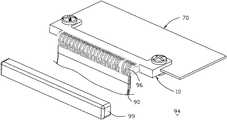
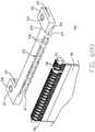
- FIG. 1is a perspective view of an electrical assembly according to a first embodiment of the invention
- FIG. 2is another perspective view of the electrical assembly of FIG. 1 ;
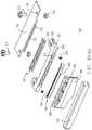
- FIG. 3is a perspective view of an inner side part of the electrical assembly of FIG. 1 without the over-molding cover of the corresponding electrical connector is removed away therefrom;
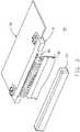
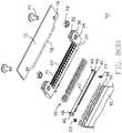
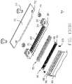
- FIG. 4(A)is a further exploded perspective view of the inner side part of the electrical assembly of FIG. 3 ;
- FIG. 4(B)is another exploded perspective view of the inner side part of the electrical assembly of FIG. 4 ;
- FIG. 5is a perspective view of the electrical connector of the electrical assembly of FIG. 1 with the associated cable wherein the over-molding cover is removed therefrom;
- FIG. 6(A)is an exploded perspective view of the electrical connector of the electrical assembly of FIG. 5 ;
- FIG. 6(B)is another exploded perspective view of the electrical connector of the electrical assembly of FIG. 6(A) ;
- FIG. 7(A)is a perspective view of the electrical connector of the electrical assembly of FIG. 5 .
- FIG. 7(B)is another perspective view of the electrical connector of the electrical assembly of FIG. 7(A) ;
- FIG. 8(A)is an exploded perspective view of the inner side part of the electrical assembly of FIG. 3 ;
- FIG. 8(B)is another exploded perspective view of the inner side part of the electrical assembly of FIG. 8(A) ;
- FIG. 9is a side view of the inner side part of the electrical assembly of FIG. 3
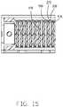
- FIG. 10is a cross-sectional view of the inner side part of the electrical assembly of FIG. 3 ;
- FIG. 11is another cross-sectional view of the inner side part of the electrical assembly of FIG. 3 ;
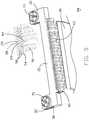
- FIG. 12(A)is an exploded perspective view of the electrical connector of the electrical assembly with the associated cable wherein the over-molding cover is removed therefrom, according to a second embodiment of the invention
- FIG. 12(B)is another exploded perspective view of the electrical connector of the electrical assembly of FIG. 12(B) ;
- FIG. 13(A)is an exploded perspective view of the inner side part of the electrical assembly of FIG. 12(A) ;
- FIG. 13(B)is another exploded perspective view of the inner side part of the electrical assembly of FIG. 13(A) ;
- FIG. 14is a cross-sectional view of the inner side part of the electrical assembly of FIG. 12(A) ;
- FIG. 15is another cross-sectional view of the inner side part of the electrical assembly of FIG. 12(A) .
- an electrical assembly 1includes a flat cable 90 composed of a plurality of coaxial wires 96 and equipped with an outer side part 92 including an outside connector 80 at the outer end region of the cable 90 wherein the outside connector 80 can be MCIO, GenZ or SlimLine type connector.
- the outside connector 80is used to mate with a board connector 80 A mounted on a printed circuit board (not shown).
- the cable 90further includes an inner side part 94 at the inner end region.
- the inner side part 94includes an electrical connector 10 connected to an inner end region of the cable 90 .
- the electrical connector 10is used to mate with an electric card 70 , that means the electrical connector 10 is a kind of card edge connector.
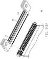
- the card edge connector 10includes a longitudinal insulative housing 20 forming a rear side and a front side opposite to each other in the front-to-back direction, the front side is defined to contract with the electrical card 80 .
- the housing 20forms a central slot 22 extending along a longitudinal direction perpendicular to the front-to-back direction in the front side, and two rows of passageways 24 located by two sides of the central slot 22 in the transverse direction perpendicular to both the front-to-back direction and the longitudinal direction, wherein each row of the passageways extends along the longitudinal direction while each passageway extends through the housing 20 in the front-to-back direction.
- An alignment key 21is formed in the central slot 22 for orientation consideration of the mated electronic card 70 .
- Each contact 50includes a front deflectable contacting section 52 extending into the central slot 22 , a rear connecting section 54 exposed outside the rear side, and a middle retaining section 56 with barbed structures 53 for retaining the contact 50 in position within the corresponding passageway 24 .
- a front positioning block 26includes a plurality of partitions 28 unitarily formed on a rear side of the housing 20 along so as to separate/isolate the connecting sections 54 of the neighboring contacts 50 from one another along the longitudinal direction.
- Each partition 28further forms a pair of sideward protrusions 29 for confining the inner conductors 98 of the tiny wires (not labeled) of the corresponding wire 96 of the cable 90 , which will be illustrated later.
- the pair of sideward protrusions 29also prevent each connecting section 54 from an upward movement.
- a rear positioning block 40 discrete from the housing 20includes a longitudinal main body 42 extending along the longitudinal direction, and two rows of dividers 44 formed on opposite upper and lower surfaces for separating/isolating the neighboring wires 96 .
- the housing 20forms a pair of receiving seats 27 at two opposite ends of the front positioning block 26 , each receiving seat 27 being equipped with a post 25 and an L-shaped reinforcement pad 23 .
- the rear positioning block 40forms a pair of protrusions 46 at two opposite ends to be received within the corresponding receiving seats 27 , respectively. Each protrusion 46 forms a pocket 48 to receive the corresponding post 25 for alignment consideration.
- the wire 96is received within the corresponding groove formed between two adjacent dividers 44 , and the corresponding inner conductor 98 is received within the space between the two corresponding sideward protrusions 29 of the two partitions 28 to be secured/soldered to the connecting section 54 of the corresponding contact 50 .
- An over-molding cover 99encloses the front portions of the wires 96 , including the rear positioning block 40 and the front positioning block 26 . In this embodiment, the over-molding cover 99 may enter a rear part of the corresponding passageways 24 .
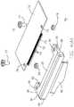
- the housing 20further includes a pair of side arms 30 forwardly extending from two opposite longitudinal ends and at opposite ends of the central slot 22 .
- Each side arm 30forms a groove 32 in alignment with the central slot 22 .
- Each side arm 30includes a securing hole 34 therein along the transverse direction.
- the electronic card 70i.e., PCIe card, has a mating edge region 72 with corresponding conductive pads 74 thereon, protruding forwards from one edge thereof.
- a alignment notch 75is formed in the mating edge region 72 for receiving the corresponding key 21 in the central slot 22 .
- a pair of mounting holes 76are formed on two sides of the mating edge region 72 .
- the mating edge region 72is received within the central slot 22 , and the electronic card 70 is assembled to the housing 20 via a pair of screws 77 each extending through the corresponding securing hole 34 and mounting hole 76 and locked by a corresponding nut 79 .
- the instant inventionCompared with the conventional design using the inside connector for receiving an electronic card, in the inner side part, mounted upon the printed circuit board and indirectly connected to the cable which connects to the outside connector, the instant invention has the cable directly connected to the inside connector and the inside connector is equipped with a pair of side arms to directly lock the electronic card via screws extending through the corresponding side arms. Therefore, the whole connection system is simplified. It is noted that in this embodiment the front positioning block is unitarily formed on the housing while the rear positioning block is formed discretely. Anyhow, the front positioning block can be unified with the rear positioning block rather than with the housing.
- FIGS. 12-15show another embodiment in which the rear positioning block 40 includes a plurality of ribs 49 forwardly extending from the main body 42 to be inserted into the corresponding passageways 24 for abutting against the connecting sections 54 of the corresponding contacts 50 in the transverse direction, respectively.
- the over-molding cover 99does not enter the passageways 24 .
Landscapes
- Details Of Connecting Devices For Male And Female Coupling (AREA)
- Coupling Device And Connection With Printed Circuit (AREA)
- Connector Housings Or Holding Contact Members (AREA)
Abstract
Description
- This application claims the benefit of, priority to, U.S. Provisional Patent Application No. 62/946945 filed Dec. 11, 2019, the contents of which are incorporated entirely herein by reference
- The present disclosure relates to an electrical assembly, and more particularly to a card edge connector with the wires permanently secured to one side, and an electronic card detachably attached to the other side.
- To reduce unwanted impedance or energy loss during signal transmission on the conductive traces on the main printed circuit board, a cable composed of plural wires is used to connect two opposite regions on the main board wherein the two opposite ends are respectfully equipped with corresponding connectors for mating with the corresponding board-mount mating connectors which are mounted upon the main board. Notably, other board-mount connectors are proximal to the corresponding board-mount connectors so as to electrically connect other/external components to those corresponding board-mount mating connectors for operation of those other/external components. Anyhow, the arrangement of using too many connectors along the transmission line also affects efficiencies of signal transmission disadvantageously.
- An improved arrangement is desired to have the cable directly electrically connect to the other component via a signal connector rather than cooperation of plural connectors.
- An object of the invention is to provide an electrical connector with one cable secured on a rear side, and an electronic card detachably attached on a front side opposite to the rear side in a front-to-back direction. The connector includes an insulative housing forming in the front side a central receiving slot with two rows of passageways by two sides of the central slot in a transverse direction perpendicular to the front-to-back direction. Each passageway extends through the housing in the front-to-back direction. Two rows of contacts are respectively inserted forwardly into the corresponding passageways from the rear side. Each contact includes a front contacting section extending into the central slot, and a rear connecting section exposed on the rear side.
- Another object of the invention is to provide an electrical assembly with mated receptacle connector and plug connector. Both the receptacle connector and the plug connector are equipped with corresponding metallic inner shells for grounding and shielding and corresponding insulative outer shell for coupling and locking wherein the plug connector further includes a resilient latch engageable with a locking step formed on the receptacle connector.
- Other objects, advantages and novel features of the disclosure will become more apparent from the following detailed description when taken in conjunction with the accompanying drawings.
FIG. 1 is a perspective view of an electrical assembly according to a first embodiment of the invention;FIG. 2 is another perspective view of the electrical assembly ofFIG. 1 ;FIG. 3 is a perspective view of an inner side part of the electrical assembly ofFIG. 1 without the over-molding cover of the corresponding electrical connector is removed away therefrom;FIG. 4(A) is a further exploded perspective view of the inner side part of the electrical assembly ofFIG. 3 ;FIG. 4(B) is another exploded perspective view of the inner side part of the electrical assembly ofFIG. 4 ;FIG. 5 is a perspective view of the electrical connector of the electrical assembly ofFIG. 1 with the associated cable wherein the over-molding cover is removed therefrom;FIG. 6(A) is an exploded perspective view of the electrical connector of the electrical assembly ofFIG. 5 ;FIG. 6(B) is another exploded perspective view of the electrical connector of the electrical assembly ofFIG. 6(A) ;FIG. 7(A) is a perspective view of the electrical connector of the electrical assembly ofFIG. 5 .FIG. 7(B) is another perspective view of the electrical connector of the electrical assembly ofFIG. 7(A) ;FIG. 8(A) is an exploded perspective view of the inner side part of the electrical assembly ofFIG. 3 ;FIG. 8(B) is another exploded perspective view of the inner side part of the electrical assembly ofFIG. 8(A) ;FIG. 9 is a side view of the inner side part of the electrical assembly ofFIG. 3 FIG. 10 is a cross-sectional view of the inner side part of the electrical assembly ofFIG. 3 ;FIG. 11 is another cross-sectional view of the inner side part of the electrical assembly ofFIG. 3 ;FIG. 12(A) is an exploded perspective view of the electrical connector of the electrical assembly with the associated cable wherein the over-molding cover is removed therefrom, according to a second embodiment of the invention;FIG. 12(B) is another exploded perspective view of the electrical connector of the electrical assembly ofFIG. 12(B) ;FIG. 13(A) is an exploded perspective view of the inner side part of the electrical assembly ofFIG. 12(A) ;FIG. 13(B) is another exploded perspective view of the inner side part of the electrical assembly ofFIG. 13(A) ;FIG. 14 is a cross-sectional view of the inner side part of the electrical assembly ofFIG. 12(A) ; andFIG. 15 is another cross-sectional view of the inner side part of the electrical assembly ofFIG. 12(A) .- Referring to
FIGS. 1-11 , anelectrical assembly 1 includes aflat cable 90 composed of a plurality ofcoaxial wires 96 and equipped with anouter side part 92 including anoutside connector 80 at the outer end region of thecable 90 wherein theoutside connector 80 can be MCIO, GenZ or SlimLine type connector. Theoutside connector 80 is used to mate with aboard connector 80A mounted on a printed circuit board (not shown). Thecable 90 further includes aninner side part 94 at the inner end region. Theinner side part 94 includes anelectrical connector 10 connected to an inner end region of thecable 90. Theelectrical connector 10 is used to mate with anelectric card 70, that means theelectrical connector 10 is a kind of card edge connector. Thecard edge connector 10 includes a longitudinalinsulative housing 20 forming a rear side and a front side opposite to each other in the front-to-back direction, the front side is defined to contract with theelectrical card 80. Thehousing 20 forms acentral slot 22 extending along a longitudinal direction perpendicular to the front-to-back direction in the front side, and two rows ofpassageways 24 located by two sides of thecentral slot 22 in the transverse direction perpendicular to both the front-to-back direction and the longitudinal direction, wherein each row of the passageways extends along the longitudinal direction while each passageway extends through thehousing 20 in the front-to-back direction. Analignment key 21 is formed in thecentral slot 22 for orientation consideration of the matedelectronic card 70. - Two rows of
contacts 50 are forwardly inserted, from the rear side of thehousing 20, into thecorresponding passageways 24, respectively. Eachcontact 50 includes a frontdeflectable contacting section 52 extending into thecentral slot 22, a rear connectingsection 54 exposed outside the rear side, and amiddle retaining section 56 withbarbed structures 53 for retaining thecontact 50 in position within thecorresponding passageway 24. Afront positioning block 26 includes a plurality ofpartitions 28 unitarily formed on a rear side of thehousing 20 along so as to separate/isolate the connectingsections 54 of the neighboringcontacts 50 from one another along the longitudinal direction. Eachpartition 28 further forms a pair ofsideward protrusions 29 for confining theinner conductors 98 of the tiny wires (not labeled) of thecorresponding wire 96 of thecable 90, which will be illustrated later. The pair ofsideward protrusions 29 also prevent each connectingsection 54 from an upward movement. - A
rear positioning block 40 discrete from thehousing 20, includes a longitudinalmain body 42 extending along the longitudinal direction, and two rows ofdividers 44 formed on opposite upper and lower surfaces for separating/isolating the neighboringwires 96. Thehousing 20 forms a pair of receivingseats 27 at two opposite ends of thefront positioning block 26, each receivingseat 27 being equipped with a post25 and an L-shaped reinforcement pad 23. Therear positioning block 40 forms a pair ofprotrusions 46 at two opposite ends to be received within thecorresponding receiving seats 27, respectively. Eachprotrusion 46 forms apocket 48 to receive thecorresponding post 25 for alignment consideration. Notably, thewire 96 is received within the corresponding groove formed between twoadjacent dividers 44, and the correspondinginner conductor 98 is received within the space between the two correspondingsideward protrusions 29 of the twopartitions 28 to be secured/soldered to the connectingsection 54 of thecorresponding contact 50. An over-moldingcover 99 encloses the front portions of thewires 96, including therear positioning block 40 and thefront positioning block 26. In this embodiment, the over-moldingcover 99 may enter a rear part of thecorresponding passageways 24. - The
housing 20 further includes a pair ofside arms 30 forwardly extending from two opposite longitudinal ends and at opposite ends of thecentral slot 22. Eachside arm 30 forms agroove 32 in alignment with thecentral slot 22. Eachside arm 30 includes a securinghole 34 therein along the transverse direction. Theelectronic card 70, i.e., PCIe card, has amating edge region 72 with correspondingconductive pads 74 thereon, protruding forwards from one edge thereof. Aalignment notch 75 is formed in themating edge region 72 for receiving the corresponding key21 in thecentral slot 22. A pair of mountingholes 76 are formed on two sides of themating edge region 72. After assembled, themating edge region 72 is received within thecentral slot 22, and theelectronic card 70 is assembled to thehousing 20 via a pair ofscrews 77 each extending through the corresponding securinghole 34 and mountinghole 76 and locked by a correspondingnut 79. - Compared with the conventional design using the inside connector for receiving an electronic card, in the inner side part, mounted upon the printed circuit board and indirectly connected to the cable which connects to the outside connector, the instant invention has the cable directly connected to the inside connector and the inside connector is equipped with a pair of side arms to directly lock the electronic card via screws extending through the corresponding side arms. Therefore, the whole connection system is simplified. It is noted that in this embodiment the front positioning block is unitarily formed on the housing while the rear positioning block is formed discretely. Anyhow, the front positioning block can be unified with the rear positioning block rather than with the housing.
FIGS. 12-15 show another embodiment in which therear positioning block 40 includes a plurality ofribs 49 forwardly extending from themain body 42 to be inserted into the correspondingpassageways 24 for abutting against the connectingsections 54 of the correspondingcontacts 50 in the transverse direction, respectively. In other words, theover-molding cover 99 does not enter thepassageways 24.- While a preferred embodiment in accordance with the present disclosure has been shown and described, equivalent modifications and changes known to persons skilled in the art according to the spirit of the present disclosure are considered within the scope of the present disclosure as described in the appended claims.
Claims (13)
Priority Applications (1)
| Application Number | Priority Date | Filing Date | Title |
|---|---|---|---|
| US17/117,577US20210184378A1 (en) | 2019-12-11 | 2020-12-10 | Eletrical assembly for use with card edge connector and cable in system |
Applications Claiming Priority (2)
| Application Number | Priority Date | Filing Date | Title |
|---|---|---|---|
| US201962946945P | 2019-12-11 | 2019-12-11 | |
| US17/117,577US20210184378A1 (en) | 2019-12-11 | 2020-12-10 | Eletrical assembly for use with card edge connector and cable in system |
Publications (1)
| Publication Number | Publication Date |
|---|---|
| US20210184378A1true US20210184378A1 (en) | 2021-06-17 |
Family
ID=76234611
Family Applications (2)
| Application Number | Title | Priority Date | Filing Date |
|---|---|---|---|
| US17/117,563ActiveUS11411354B2 (en) | 2019-12-11 | 2020-12-10 | Electrical connector assembly with a pair of differential terminals |
| US17/117,577AbandonedUS20210184378A1 (en) | 2019-12-11 | 2020-12-10 | Eletrical assembly for use with card edge connector and cable in system |
Family Applications Before (1)
| Application Number | Title | Priority Date | Filing Date |
|---|---|---|---|
| US17/117,563ActiveUS11411354B2 (en) | 2019-12-11 | 2020-12-10 | Electrical connector assembly with a pair of differential terminals |
Country Status (3)
| Country | Link |
|---|---|
| US (2) | US11411354B2 (en) |
| CN (2) | CN112952483A (en) |
| TW (2) | TWI783315B (en) |
Cited By (1)
| Publication number | Priority date | Publication date | Assignee | Title |
|---|---|---|---|---|
| USD1082732S1 (en)* | 2025-01-28 | 2025-07-08 | Xiuling Li | Circuit board |
Families Citing this family (5)
| Publication number | Priority date | Publication date | Assignee | Title |
|---|---|---|---|---|
| USD908089S1 (en)* | 2018-06-08 | 2021-01-19 | Norman R. Byrne | Electrical connector |
| TWM619833U (en)* | 2021-04-28 | 2021-11-21 | 禾昌興業股份有限公司 | Connector |
| CN113594735B (en)* | 2021-07-29 | 2023-12-08 | 苏州意华通讯接插件有限公司 | Card edge connector |
| CN113594734B (en)* | 2021-07-29 | 2024-01-09 | 苏州意华通讯接插件有限公司 | Card edge connector |
| TWI826210B (en)* | 2022-12-28 | 2023-12-11 | 神雲科技股份有限公司 | Adapting device |
Citations (5)
| Publication number | Priority date | Publication date | Assignee | Title |
|---|---|---|---|---|
| CN103515757A (en)* | 2012-06-19 | 2014-01-15 | 凡甲电子(苏州)有限公司 | Cable connector assembly |
| TWM472344U (en)* | 2013-07-31 | 2014-02-11 | Ant Prec Industry Co Ltd | Electrical connector and the electrical system using the same |
| US9941646B1 (en)* | 2016-10-06 | 2018-04-10 | Dai-Ichi Seiko Co., Ltd. | Coaxial cable connector and method of use thereof |
| US10050364B1 (en)* | 2017-07-19 | 2018-08-14 | Lenovo (Singapore) Pte. Ltd. | Flexible printed circuit connector and electronic device provided with the same |
| US20210351544A1 (en)* | 2018-10-05 | 2021-11-11 | University Of Florida Research Foundation, Incorporated | Reliable Miniature Implantable Connector With High Channel Density And Methods Of Using The Same |
Family Cites Families (18)
| Publication number | Priority date | Publication date | Assignee | Title |
|---|---|---|---|---|
| JP2910631B2 (en)* | 1995-07-07 | 1999-06-23 | 住友電装株式会社 | Shield connector |
| JPH11102752A (en)* | 1997-09-29 | 1999-04-13 | Yazaki Corp | Shield connector |
| JP3229272B2 (en)* | 1998-10-21 | 2001-11-19 | ヒロセ電機株式会社 | Shield connector |
| US6905364B2 (en) | 2003-09-17 | 2005-06-14 | Osram Sylvania, Inc. | High frequency right angle connector |
| JP2006236657A (en)* | 2005-02-23 | 2006-09-07 | Nec Corp | Connector device |
| CN201315360Y (en)* | 2008-12-20 | 2009-09-23 | 蔡添庆 | Clamping plate type electric connector |
| TWI377737B (en)* | 2008-12-29 | 2012-11-21 | Hon Hai Prec Ind Co Ltd | Cable connector assembly |
| TW201407320A (en)* | 2012-08-15 | 2014-02-16 | Hon Hai Prec Ind Co Ltd | Electronic device |
| US9905944B2 (en)* | 2013-07-19 | 2018-02-27 | Foxconn Interconnect Technology Limited | Flippable electrical connector |
| CN203787601U (en)* | 2014-03-14 | 2014-08-20 | 东莞世华电子有限公司 | A connector connected by a flat cable |
| CN205248528U (en)* | 2015-11-26 | 2016-05-18 | 湖北高宏通电子科技有限公司 | Vertical type draw -in groove connector component |
| CN108110497B (en)* | 2016-11-23 | 2020-12-22 | 富士康(昆山)电脑接插件有限公司 | Cable assembly with improved cable retention |
| EP3396793B1 (en) | 2017-04-28 | 2020-08-26 | Rosenberger Hochfrequenztechnik GmbH & Co. KG | Contact body for a connector |
| WO2019136199A2 (en)* | 2018-01-05 | 2019-07-11 | Molex, Llc | Low profile electrical connector system with differential pair cable interface |
| CN110556659B (en)* | 2018-05-30 | 2022-06-21 | 富士康(昆山)电脑接插件有限公司 | Electrical connector with improved contact arrangement |
| CN209029589U (en)* | 2018-08-25 | 2019-06-25 | 广州连捷新能源科技有限公司 | Plastic cement connector plug structure |
| CN209200290U (en)* | 2019-02-14 | 2019-08-02 | 深圳市瑞霸新能科技有限公司 | Radio frequency connector and signal transmission system |
| CN110391529B (en)* | 2019-08-13 | 2020-12-22 | 番禺得意精密电子工业有限公司 | Cable connector and cable connector combination thereof |
- 2020
- 2020-11-19CNCN202011300865.1Apatent/CN112952483A/enactivePending
- 2020-11-19CNCN202011300881.0Apatent/CN112952425A/enactivePending
- 2020-12-07TWTW109142975Apatent/TWI783315B/enactive
- 2020-12-08TWTW109143125Apatent/TWI844753B/enactive
- 2020-12-10USUS17/117,563patent/US11411354B2/enactiveActive
- 2020-12-10USUS17/117,577patent/US20210184378A1/ennot_activeAbandoned
Patent Citations (6)
| Publication number | Priority date | Publication date | Assignee | Title |
|---|---|---|---|---|
| CN103515757A (en)* | 2012-06-19 | 2014-01-15 | 凡甲电子(苏州)有限公司 | Cable connector assembly |
| CN103515757B (en)* | 2012-06-19 | 2016-02-10 | 凡甲电子(苏州)有限公司 | Micro coaxial cable connector assembly |
| TWM472344U (en)* | 2013-07-31 | 2014-02-11 | Ant Prec Industry Co Ltd | Electrical connector and the electrical system using the same |
| US9941646B1 (en)* | 2016-10-06 | 2018-04-10 | Dai-Ichi Seiko Co., Ltd. | Coaxial cable connector and method of use thereof |
| US10050364B1 (en)* | 2017-07-19 | 2018-08-14 | Lenovo (Singapore) Pte. Ltd. | Flexible printed circuit connector and electronic device provided with the same |
| US20210351544A1 (en)* | 2018-10-05 | 2021-11-11 | University Of Florida Research Foundation, Incorporated | Reliable Miniature Implantable Connector With High Channel Density And Methods Of Using The Same |
Cited By (1)
| Publication number | Priority date | Publication date | Assignee | Title |
|---|---|---|---|---|
| USD1082732S1 (en)* | 2025-01-28 | 2025-07-08 | Xiuling Li | Circuit board |
Also Published As
| Publication number | Publication date |
|---|---|
| TWI783315B (en) | 2022-11-11 |
| US11411354B2 (en) | 2022-08-09 |
| CN112952425A (en) | 2021-06-11 |
| TWI844753B (en) | 2024-06-11 |
| CN112952483A (en) | 2021-06-11 |
| TW202127751A (en) | 2021-07-16 |
| TW202131559A (en) | 2021-08-16 |
| US20210184403A1 (en) | 2021-06-17 |
Similar Documents
| Publication | Publication Date | Title |
|---|---|---|
| USRE49901E1 (en) | Electrical receptacle for transmitting high speed signal | |
| US20210184378A1 (en) | Eletrical assembly for use with card edge connector and cable in system | |
| US11715907B2 (en) | Electrical connector with fool-proof function | |
| US10574003B2 (en) | Electrical connectors with reinforced structure | |
| US9905944B2 (en) | Flippable electrical connector | |
| US9912111B2 (en) | Flippable electrical connector | |
| US9490549B2 (en) | Flippable electrical connector | |
| US9653849B2 (en) | Electrical connector having good anti-EMI perfprmance | |
| US9490594B2 (en) | Flippable electrical connector | |
| US6431914B1 (en) | Grounding scheme for a high speed backplane connector system | |
| US6739904B2 (en) | Cable connector assembly | |
| US20090215315A1 (en) | Power connector with improved contacts | |
| US9698540B2 (en) | Cable connector assembly having internal metallic shield | |
| US20100068922A1 (en) | Cable connector assembly having improved grounding member | |
| US9997872B2 (en) | Cable connector assembly having aligned solder tails for connecting to resistor | |
| US20090130888A1 (en) | Cable connector | |
| CN210350162U (en) | Electrical connector | |
| US12003061B2 (en) | Ground structure for a cable card assembly of an electrical connector | |
| CN111082242B (en) | Connector, circuit board and communication equipment | |
| US10236599B2 (en) | Grounding collar connected with grounding terminal | |
| US7086889B2 (en) | Interlocking member for an electrical connector | |
| JP5315912B2 (en) | Multiple electrical connector | |
| KR102550876B1 (en) | Connector for coaxial cable | |
| US6368151B1 (en) | Electrical connector assembly | |
| US11831108B2 (en) | Cable connector with improved metallic shield |
Legal Events
| Date | Code | Title | Description |
|---|---|---|---|
| AS | Assignment | Owner name:FOXCONN (KUNSHAN) COMPUTER CONNECTOR CO., LTD., CHINA Free format text:ASSIGNMENT OF ASSIGNORS INTEREST;ASSIGNOR:LITTLE, TERRANCE F.;REEL/FRAME:054605/0208 Effective date:20201201 Owner name:FOXCONN INTERCONNECT TECHNOLOGY LIMITED, CAYMAN ISLANDS Free format text:ASSIGNMENT OF ASSIGNORS INTEREST;ASSIGNOR:LITTLE, TERRANCE F.;REEL/FRAME:054605/0208 Effective date:20201201 | |
| STPP | Information on status: patent application and granting procedure in general | Free format text:APPLICATION DISPATCHED FROM PREEXAM, NOT YET DOCKETED | |
| STPP | Information on status: patent application and granting procedure in general | Free format text:DOCKETED NEW CASE - READY FOR EXAMINATION | |
| STPP | Information on status: patent application and granting procedure in general | Free format text:NON FINAL ACTION MAILED | |
| STPP | Information on status: patent application and granting procedure in general | Free format text:RESPONSE TO NON-FINAL OFFICE ACTION ENTERED AND FORWARDED TO EXAMINER | |
| STPP | Information on status: patent application and granting procedure in general | Free format text:FINAL REJECTION MAILED | |
| STPP | Information on status: patent application and granting procedure in general | Free format text:RESPONSE AFTER FINAL ACTION FORWARDED TO EXAMINER | |
| STPP | Information on status: patent application and granting procedure in general | Free format text:ADVISORY ACTION MAILED | |
| STPP | Information on status: patent application and granting procedure in general | Free format text:RESPONSE AFTER FINAL ACTION FORWARDED TO EXAMINER | |
| STPP | Information on status: patent application and granting procedure in general | Free format text:ADVISORY ACTION MAILED | |
| STCB | Information on status: application discontinuation | Free format text:ABANDONED -- FAILURE TO RESPOND TO AN OFFICE ACTION |