US20200090558A1 - T- Post Sign Attachment Apparatus - Google Patents
T- Post Sign Attachment ApparatusDownload PDFInfo
- Publication number
- US20200090558A1 US20200090558A1US16/134,718US201816134718AUS2020090558A1US 20200090558 A1US20200090558 A1US 20200090558A1US 201816134718 AUS201816134718 AUS 201816134718AUS 2020090558 A1US2020090558 A1US 2020090558A1
- Authority
- US
- United States
- Prior art keywords
- post
- face plate
- pair
- coupled
- cap
- Prior art date
- Legal status (The legal status is an assumption and is not a legal conclusion. Google has not performed a legal analysis and makes no representation as to the accuracy of the status listed.)
- Abandoned
Links
- 230000000284resting effectEffects0.000claims1
- 238000012986modificationMethods0.000description2
- 230000004048modificationEffects0.000description2
- 238000010276constructionMethods0.000description1
Images


Classifications
- G—PHYSICS
- G09—EDUCATION; CRYPTOGRAPHY; DISPLAY; ADVERTISING; SEALS
- G09F—DISPLAYING; ADVERTISING; SIGNS; LABELS OR NAME-PLATES; SEALS
- G09F7/00—Signs, name or number plates, letters, numerals, or symbols; Panels or boards
- G09F7/18—Means for attaching signs, plates, panels, or boards to a supporting structure
- G09F2007/1804—Means for attaching signs, plates, panels, or boards to a supporting structure for fastening to a post
- G09F2007/1817—Means for attaching signs, plates, panels, or boards to a supporting structure for fastening to a post using fastening means to grip the post
Definitions
- the disclosure and prior artrelates to sign attachment systems and more particularly pertains to a new sign attachment system for mounting a sign to a t-post.
- An embodiment of the disclosuremeets the needs presented above by generally comprising a rectangular prismatic face plate having a post side, a back side, a top edge, and a bottom edge.
- a capis coupled to the post side of the face plate adjacent the top edge.
- the capcomprises a vertical wall and a horizontal top side continuously disposed on an upper edge of the vertical wall.
- the capis configured to rest on a standard t-post.
- a pair of hooksis coupled to the face plate adjacent the bottom edge and is configured to slidably engage with the standard t-post.
- a sign bodycoupled to the face plate, the sign body being coplanarly coupled to the top edge of the face plate.
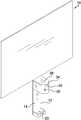
- FIG. 1is an isometric view of a t-post sign attachment apparatus according to an embodiment of the disclosure.
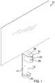
- FIG. 2is an isometric view of an embodiment of the disclosure.
- FIG. 3is a side elevation view of an embodiment of the disclosure.
- FIG. 4is a bottom plan view of an embodiment of the disclosure.
- FIG. 5is a rear elevation view of an embodiment of the disclosure.
- FIG. 6is an in-use front elevation view of an embodiment of the disclosure.
- FIGS. 1 through 6With reference now to the drawings, and in particular to FIGS. 1 through 6 thereof, a new sign attachment system embodying the principles and concepts of an embodiment of the disclosure and generally designated by the reference numeral 10 will be described.
- the t-post sign attachment apparatus 10generally comprises a rectangular prismatic face plate 12 having a post side 14 , a back side 16 , a top edge 18 , and a bottom edge 20 .
- the face plate 12may have a width 22 of at least 3.8 centimeters and a height 24 of at least 15.2 centimeters.
- the face plate 12may have a mounting aperture 26 extending through the post side 14 to the back side 16 that is configured to receive a mounting bolt 28 that passes through a post aperture of a plurality of post apertures 30 of a standard t-post 32 to secure the t-post sign attachment apparatus 10 to the t-post 32 .
- a cap 34is coupled to the post side 14 of the face plate adjacent the top edge 18 and comprises a vertical wall 36 and a horizontal top side 38 continuously disposed on an upper edge 40 of the vertical wall.
- the vertical wall 36 of the capcomprises a pair of straight walls 42 and a pair of angled walls 44 with the pair of angled walls forming a point 46 creating a pentagonal shape with the face plate 12 configured to snugly receive the t-post 32 .
- the point 46may be at least 6.3 centimeters from the face plate 12 .
- the cap 34is configured to rest on the standard t-post 32 .
- a pair of hooks 48is coupled to the post side 14 of the face plate adjacent the bottom edge 20 .
- Each of the pair of hooks 48may have an extension portion 50 and a bent portion 52 with the bent portion perpendicular the extension portion 50 .
- the extension portion 52 of each of the pair of hooksmay extend at least 2.5 centimeters from the face plate 12 .
- the pair of hooks 48is configured to slidably engage with the standard t-post 32 .
- a sign body 54is coplanarly coupled to the top edge 18 of the face plate.
- the sign body 54may display a message 56 such as “NO TRESPASSING”.
- the pair of hooks 48are slid down the t-post 32 until the t-post rests within the cap 34 .
- the mounting bolt 28is then passed through the mounting bolt aperture 26 and a post aperture of the plurality of post apertures 30 .
Landscapes
- Physics & Mathematics (AREA)
- General Physics & Mathematics (AREA)
- Engineering & Computer Science (AREA)
- Theoretical Computer Science (AREA)
- Supports Or Holders For Household Use (AREA)
- Road Signs Or Road Markings (AREA)
Abstract
Description
- Not Applicable
- Not Applicable
- Not Applicable
- Not Applicable
- Not Applicable
- The disclosure and prior art relates to sign attachment systems and more particularly pertains to a new sign attachment system for mounting a sign to a t-post.
- An embodiment of the disclosure meets the needs presented above by generally comprising a rectangular prismatic face plate having a post side, a back side, a top edge, and a bottom edge. A cap is coupled to the post side of the face plate adjacent the top edge. The cap comprises a vertical wall and a horizontal top side continuously disposed on an upper edge of the vertical wall. The cap is configured to rest on a standard t-post. A pair of hooks is coupled to the face plate adjacent the bottom edge and is configured to slidably engage with the standard t-post. A sign body coupled to the face plate, the sign body being coplanarly coupled to the top edge of the face plate.
- There has thus been outlined, rather broadly, the more important features of the disclosure in order that the detailed description thereof that follows may be better understood, and in order that the present contribution to the art may be better appreciated. There are additional features of the disclosure that will be described hereinafter and which will form the subject matter of the claims appended hereto.
- The objects of the disclosure, along with the various features of novelty which characterize the disclosure, are pointed out with particularity in the claims annexed to and forming a part of this disclosure.
- The disclosure will be better understood and objects other than those set forth above will become apparent when consideration is given to the following detailed description thereof. Such description makes reference to the annexed drawings wherein:
FIG. 1 is an isometric view of a t-post sign attachment apparatus according to an embodiment of the disclosure.FIG. 2 is an isometric view of an embodiment of the disclosure.FIG. 3 is a side elevation view of an embodiment of the disclosure.FIG. 4 is a bottom plan view of an embodiment of the disclosure.FIG. 5 is a rear elevation view of an embodiment of the disclosure.FIG. 6 is an in-use front elevation view of an embodiment of the disclosure.- With reference now to the drawings, and in particular to
FIGS. 1 through 6 thereof, a new sign attachment system embodying the principles and concepts of an embodiment of the disclosure and generally designated by thereference numeral 10 will be described. - As best illustrated in
FIGS. 1 through 6 , the t-postsign attachment apparatus 10 generally comprises a rectangularprismatic face plate 12 having apost side 14, aback side 16, atop edge 18, and abottom edge 20. Theface plate 12 may have awidth 22 of at least 3.8 centimeters and aheight 24 of at least 15.2 centimeters. Theface plate 12 may have amounting aperture 26 extending through thepost side 14 to theback side 16 that is configured to receive amounting bolt 28 that passes through a post aperture of a plurality of post apertures30 of a standard t-post 32 to secure the t-postsign attachment apparatus 10 to the t-post 32. Acap 34 is coupled to thepost side 14 of the face plate adjacent thetop edge 18 and comprises avertical wall 36 and ahorizontal top side 38 continuously disposed on anupper edge 40 of the vertical wall. Thevertical wall 36 of the cap comprises a pair ofstraight walls 42 and a pair ofangled walls 44 with the pair of angled walls forming apoint 46 creating a pentagonal shape with theface plate 12 configured to snugly receive the t-post 32. Thepoint 46 may be at least 6.3 centimeters from theface plate 12. Thecap 34 is configured to rest on the standard t-post 32. A pair ofhooks 48 is coupled to thepost side 14 of the face plate adjacent thebottom edge 20. Each of the pair ofhooks 48 may have an extension portion50 and a bent portion52 with the bent portion perpendicular the extension portion50. The extension portion52 of each of the pair of hooks may extend at least 2.5 centimeters from theface plate 12. The pair ofhooks 48 is configured to slidably engage with the standard t-post 32. Asign body 54 is coplanarly coupled to thetop edge 18 of the face plate. Thesign body 54 may display amessage 56 such as “NO TRESPASSING”. - In use, the pair of
hooks 48 are slid down the t-post 32 until the t-post rests within thecap 34. Themounting bolt 28 is then passed through themounting bolt aperture 26 and a post aperture of the plurality of post apertures30. - With respect to the above description then, it is to be realized that the optimum dimensional relationships for the parts of an embodiment enabled by the disclosure, to include variations in size, materials, shape, form, function and manner of operation, assembly and use, are deemed readily apparent and obvious to one skilled in the art, and all equivalent relationships to those illustrated in the drawings and described in the specification are intended to be encompassed by an embodiment of the disclosure.
- Therefore, the foregoing is considered as illustrative only of the principles of the disclosure. Further, since numerous modifications and changes will readily occur to those skilled in the art, it is not desired to limit the disclosure to the exact construction and operation shown and described, and accordingly, all suitable modifications and equivalents may be resorted to, falling within the scope of the disclosure. In this patent document, the word “comprising” is used in its non-limiting sense to mean that items following the word are included, but items not specifically mentioned are not excluded. A reference to an element by the indefinite article “a” does not exclude the possibility that more than one of the element is present, unless the context clearly requires that there be only one of the elements.
Claims (8)
1. A t-post sign attachment apparatus comprising:
a rectangular prismatic face plate having a post side, a back side, a top edge, and a bottom edge;
a cap coupled to the face plate, the cap being coupled to the post side adjacent the top edge, the cap comprising a vertical wall and a horizontal top side continuously disposed on an upper edge of the vertical wall, the cap being configured to rest on a standard t-post;
a pair of hooks coupled to the face plate, the pair of hooks being coupled to the post side adjacent the bottom edge, the pair of hooks being configured to slidably engage with the standard t-post, each of the pair of hooks having an extension portion and a bent portion, the extension portion extending between the face plate and the bent portion, the bent portion extending perpendicularly from the extension portion wherein the bent portion is parallel to the face plate, the bent portions of the pair of hooks extending from the extension portion towards each other and terminating defining a gap therebetween; and
a sign body coupled to the face plate, the sign body being coplanarly coupled to the top edge of the face plate.
2. The t-post sign attachment apparatus ofclaim 1 further comprising the face plate having a mounting aperture extending through the post side to the back side, the mounting bolt aperture being configured to receive a mounting bolt engages the standard t-post to secure the t-post sign attachment apparatus to the t-post.
3. The t-post sign attachment apparatus ofclaim 1 further comprising the vertical wall of the cap comprising a pair of straight walls and a pair of angled walls, the pair of angled walls forming a point.
4. (canceled)
5. The t-post sign attachment apparatus ofclaim 1 further comprising the extension portion of each of the pair of hooks extending at least 2.5 centimeters from the face plate and the point of the vertical wall of the cap being at least 6.3 centimeters from the face plate, the face plate having a width of at least 3.8 centimeters and a height of at least 15.2 centimeters.
6. A t-post sign attachment apparatus comprising:
a rectangular prismatic face plate having a post side, a back side, a top edge, and a bottom edge, the face plate having a mounting aperture extending through the post side to the back side, the mounting bolt aperture being configured to receive a mounting bolt that engages a standard t-post to secure the t-post sign attachment apparatus to the t-post;
a cap coupled to the face plate, the cap being coupled to the post side adjacent the top edge, the cap comprising a vertical wall and a horizontal top side continuously disposed on an upper edge of the vertical wall, the vertical wall of the cap comprising a pair of straight walls and a pair of angled walls, the pair of angled walls forming a point, the cap being configured to rest on a standard t-post;
a pair of hooks coupled to the face plate, the pair of hooks being coupled to the post side adjacent the bottom edge, each of the pair of hooks having an extension portion and a bent portion, the extension portion extending between the face plate and the bent portion, the bent portion extending perpendicularly from the extension portion wherein the bent portion is parallel to the face plate, the bent portions of the pair of hooks extending from the extension portion towards each other and terminating defining a gap therebetween, the pair of hooks being configured to slidably engage with the standard t-post; and
a sign body coupled to the face plate, the sign body being coplanarly coupled to the top edge of the face plate.
7. A t-post and t-post sign attachment apparatus combination comprising:
a t-post,
a rectangular prismatic face plate having a post side, a back side, a top edge, and a bottom edge, the face plate having a mounting aperture extending through the post side to the back side, the mounting bolt aperture being configured to receive a mounting bolt that engages the t-post sign attachment apparatus to the t-post;
a cap coupled to the face plate, the cap being coupled to the post side adjacent the top edge, the cap comprising a vertical wall and a horizontal top side continuously disposed on an upper edge of the vertical wall, the vertical wall of the cap comprising a pair of straight walls and a pair of angled walls, the pair of angled walls forming a point, the cap resting on the t-post;
a pair of hooks coupled to the face plate, the pair of hooks being coupled to the post side adjacent the bottom edge, each of the pair of hooks having an extension portion and a bent portion, the extension portion extending between the face plate and the bent portion, the bent portion extending perpendicularly from the extension portion wherein the bent portion is parallel to the face plate, the bent portions of the pair of hooks extending from the extension portion towards each other and terminating defining a gap therebetween, the pair of hooks being slidably engageable with the t-post; and
a sign body coupled to the face plate, the sign body being coplanarly coupled to the top edge of the face plate.
8. The apparatus ofclaim 1 , further comprising:
the face plate having a width of at least 3.8 centimeters and a height of at least 15.2 centimeters, the face plate having a mounting aperture extending through the post side to the back side, the mounting bolt aperture being configured to receive a mounting bolt that engages standard t-post to secure the t-post sign attachment apparatus to the t-post;
the vertical wall of the cap comprising a pair of straight walls and a pair of angled walls, the pair of angled walls forming a point, the point being at least 6.3 centimeters from the face plate; and
the extension portion of each of the pair of hooks extending at least 2.5 centimeters from the face plate.
Priority Applications (1)
| Application Number | Priority Date | Filing Date | Title |
|---|---|---|---|
| US16/134,718US20200090558A1 (en) | 2018-09-18 | 2018-09-18 | T- Post Sign Attachment Apparatus |
Applications Claiming Priority (1)
| Application Number | Priority Date | Filing Date | Title |
|---|---|---|---|
| US16/134,718US20200090558A1 (en) | 2018-09-18 | 2018-09-18 | T- Post Sign Attachment Apparatus |
Publications (1)
| Publication Number | Publication Date |
|---|---|
| US20200090558A1true US20200090558A1 (en) | 2020-03-19 |
Family
ID=69774305
Family Applications (1)
| Application Number | Title | Priority Date | Filing Date |
|---|---|---|---|
| US16/134,718AbandonedUS20200090558A1 (en) | 2018-09-18 | 2018-09-18 | T- Post Sign Attachment Apparatus |
Country Status (1)
| Country | Link |
|---|---|
| US (1) | US20200090558A1 (en) |
Citations (12)
| Publication number | Priority date | Publication date | Assignee | Title |
|---|---|---|---|---|
| US1646414A (en)* | 1925-04-06 | 1927-10-25 | Charles T Marton | Sign holder |
| US2146113A (en)* | 1937-07-19 | 1939-02-07 | C E Erickson Company Inc | Sign and mounting therefor |
| US3102352A (en)* | 1961-04-03 | 1963-09-03 | Leonard L White | Sign structure |
| US3143817A (en)* | 1962-07-18 | 1964-08-11 | Paul G Paulson | Sign holders |
| US3457664A (en)* | 1966-09-07 | 1969-07-29 | Handley Ind Inc | Aerial sign |
| US4641448A (en)* | 1985-01-18 | 1987-02-10 | Apco Graphics, Inc. | Post cap apparatus |
| US5011105A (en)* | 1979-08-13 | 1991-04-30 | Refrigeration Research, Inc. | Collector stand |
| US5439201A (en)* | 1994-04-21 | 1995-08-08 | 832276 Ontario Inc. | Fence bracket |
| US5956875A (en)* | 1997-08-25 | 1999-09-28 | Aughenbaugh; Timonthy A. | Post sleeve |
| US20140263898A1 (en)* | 2013-03-15 | 2014-09-18 | Charles Aldrich | Fence post platform attachment device |
| US20150248851A1 (en)* | 2014-03-03 | 2015-09-03 | Sun Peak Development, Llc | Mounting assemblies |
| US20160290552A1 (en)* | 2015-04-06 | 2016-10-06 | Edward James Holestine | Bracket for fixing a panel to a t-post |
- 2018
- 2018-09-18USUS16/134,718patent/US20200090558A1/ennot_activeAbandoned
Patent Citations (12)
| Publication number | Priority date | Publication date | Assignee | Title |
|---|---|---|---|---|
| US1646414A (en)* | 1925-04-06 | 1927-10-25 | Charles T Marton | Sign holder |
| US2146113A (en)* | 1937-07-19 | 1939-02-07 | C E Erickson Company Inc | Sign and mounting therefor |
| US3102352A (en)* | 1961-04-03 | 1963-09-03 | Leonard L White | Sign structure |
| US3143817A (en)* | 1962-07-18 | 1964-08-11 | Paul G Paulson | Sign holders |
| US3457664A (en)* | 1966-09-07 | 1969-07-29 | Handley Ind Inc | Aerial sign |
| US5011105A (en)* | 1979-08-13 | 1991-04-30 | Refrigeration Research, Inc. | Collector stand |
| US4641448A (en)* | 1985-01-18 | 1987-02-10 | Apco Graphics, Inc. | Post cap apparatus |
| US5439201A (en)* | 1994-04-21 | 1995-08-08 | 832276 Ontario Inc. | Fence bracket |
| US5956875A (en)* | 1997-08-25 | 1999-09-28 | Aughenbaugh; Timonthy A. | Post sleeve |
| US20140263898A1 (en)* | 2013-03-15 | 2014-09-18 | Charles Aldrich | Fence post platform attachment device |
| US20150248851A1 (en)* | 2014-03-03 | 2015-09-03 | Sun Peak Development, Llc | Mounting assemblies |
| US20160290552A1 (en)* | 2015-04-06 | 2016-10-06 | Edward James Holestine | Bracket for fixing a panel to a t-post |
Similar Documents
| Publication | Publication Date | Title |
|---|---|---|
| US10117505B1 (en) | Electronic case assembly | |
| US20100044536A1 (en) | Hanging frame for display | |
| US20200060402A1 (en) | Electronic Payment Card and Key Holding Assembly | |
| US10022006B1 (en) | Clamping support assembly | |
| US20180256997A1 (en) | Vertical and lateral stackable brick assembly | |
| US10711451B2 (en) | Rack construction assembly | |
| US10617238B1 (en) | Frame reinforcement hanger apparatus | |
| US9896136B2 (en) | Truck rack system | |
| US20230250654A1 (en) | Fall Arrest Assembly | |
| US20200090558A1 (en) | T- Post Sign Attachment Apparatus | |
| US11414310B2 (en) | Cabinet lifting assembly | |
| US10847060B1 (en) | Trading card display assembly | |
| US20170280942A1 (en) | Shower Rod Support Device | |
| US20190015965A1 (en) | Motorcycle Stand Assembly | |
| US10868900B1 (en) | Cellphone stand apparatus | |
| US11142950B2 (en) | Removably attachable platform device | |
| US11220219B2 (en) | Truck step addition apparatus | |
| US10039393B1 (en) | Calendar frame assembly | |
| US11197510B2 (en) | Academic hat tassel securing system | |
| US9901194B1 (en) | Modular frame assembly | |
| US20190208833A1 (en) | Handkerchief securing assembly | |
| US11431157B2 (en) | Electrical outlet spacing system | |
| US11211683B2 (en) | Antenna mounting bracket assembly | |
| US20210140236A1 (en) | Ladder Anchoring Assembly | |
| US11510518B2 (en) | Window shelf assembly |
Legal Events
| Date | Code | Title | Description |
|---|---|---|---|
| STPP | Information on status: patent application and granting procedure in general | Free format text:RESPONSE AFTER FINAL ACTION FORWARDED TO EXAMINER | |
| STPP | Information on status: patent application and granting procedure in general | Free format text:ADVISORY ACTION MAILED | |
| STCB | Information on status: application discontinuation | Free format text:ABANDONED -- FAILURE TO RESPOND TO AN OFFICE ACTION |