US20200038064A1 - Spinal surgery systems and methods - Google Patents
Spinal surgery systems and methodsDownload PDFInfo
- Publication number
- US20200038064A1 US20200038064A1US16/434,976US201916434976AUS2020038064A1US 20200038064 A1US20200038064 A1US 20200038064A1US 201916434976 AUS201916434976 AUS 201916434976AUS 2020038064 A1US2020038064 A1US 2020038064A1
- Authority
- US
- United States
- Prior art keywords
- retaining
- bone anchor
- feature
- bone
- anchor assembly
- Prior art date
- Legal status (The legal status is an assumption and is not a legal conclusion. Google has not performed a legal analysis and makes no representation as to the accuracy of the status listed.)
- Granted
Links
- 238000000034methodMethods0.000titleclaimsdescription43
- 238000001356surgical procedureMethods0.000titledescription3
- 210000000988bone and boneAnatomy0.000claimsabstractdescription201
- 241000722921Tulipa gesnerianaSpecies0.000claimsabstractdescription65
- 230000014759maintenance of locationEffects0.000claimsabstractdescription64
- 230000000717retained effectEffects0.000claimsabstractdescription10
- 238000003780insertionMethods0.000claimsdescription2
- 230000037431insertionEffects0.000claimsdescription2
- 230000000712assemblyEffects0.000description9
- 238000000429assemblyMethods0.000description9
- 230000008878couplingEffects0.000description6
- 238000010168coupling processMethods0.000description6
- 238000005859coupling reactionMethods0.000description6
- 238000002788crimpingMethods0.000description3
- 239000012530fluidSubstances0.000description3
- 230000008569processEffects0.000description3
- 230000008901benefitEffects0.000description2
- 238000004891communicationMethods0.000description2
- 230000000295complement effectEffects0.000description2
- 230000003993interactionEffects0.000description2
- 230000004044responseEffects0.000description2
- 206010061246Intervertebral disc degenerationDiseases0.000description1
- 206010058907Spinal deformityDiseases0.000description1
- 208000007103SpondylolisthesisDiseases0.000description1
- 210000003484anatomyAnatomy0.000description1
- 238000012937correctionMethods0.000description1
- 208000018180degenerative disc diseaseDiseases0.000description1
- 230000001419dependent effectEffects0.000description1
- 238000002513implantationMethods0.000description1
- 208000021600intervertebral disc degenerative diseaseDiseases0.000description1
- 230000003447ipsilateral effectEffects0.000description1
- 239000000463materialSubstances0.000description1
- 238000012986modificationMethods0.000description1
- 230000004048modificationEffects0.000description1
Images


Classifications
- A—HUMAN NECESSITIES
- A61—MEDICAL OR VETERINARY SCIENCE; HYGIENE
- A61B—DIAGNOSIS; SURGERY; IDENTIFICATION
- A61B17/00—Surgical instruments, devices or methods
- A61B17/56—Surgical instruments or methods for treatment of bones or joints; Devices specially adapted therefor
- A61B17/58—Surgical instruments or methods for treatment of bones or joints; Devices specially adapted therefor for osteosynthesis, e.g. bone plates, screws or setting implements
- A61B17/68—Internal fixation devices, including fasteners and spinal fixators, even if a part thereof projects from the skin
- A61B17/70—Spinal positioners or stabilisers, e.g. stabilisers comprising fluid filler in an implant
- A61B17/7001—Screws or hooks combined with longitudinal elements which do not contact vertebrae
- A61B17/7032—Screws or hooks with U-shaped head or back through which longitudinal rods pass
- A—HUMAN NECESSITIES
- A61—MEDICAL OR VETERINARY SCIENCE; HYGIENE
- A61B—DIAGNOSIS; SURGERY; IDENTIFICATION
- A61B17/00—Surgical instruments, devices or methods
- A61B17/56—Surgical instruments or methods for treatment of bones or joints; Devices specially adapted therefor
- A61B17/58—Surgical instruments or methods for treatment of bones or joints; Devices specially adapted therefor for osteosynthesis, e.g. bone plates, screws or setting implements
- A61B17/68—Internal fixation devices, including fasteners and spinal fixators, even if a part thereof projects from the skin
- A61B17/70—Spinal positioners or stabilisers, e.g. stabilisers comprising fluid filler in an implant
- A61B17/7074—Tools specially adapted for spinal fixation operations other than for bone removal or filler handling
- A61B17/7076—Tools specially adapted for spinal fixation operations other than for bone removal or filler handling for driving, positioning or assembling spinal clamps or bone anchors specially adapted for spinal fixation
- A61B17/7082—Tools specially adapted for spinal fixation operations other than for bone removal or filler handling for driving, positioning or assembling spinal clamps or bone anchors specially adapted for spinal fixation for driving, i.e. rotating, screws or screw parts specially adapted for spinal fixation, e.g. for driving polyaxial or tulip-headed screws
- A—HUMAN NECESSITIES
- A61—MEDICAL OR VETERINARY SCIENCE; HYGIENE
- A61B—DIAGNOSIS; SURGERY; IDENTIFICATION
- A61B17/00—Surgical instruments, devices or methods
- A61B17/56—Surgical instruments or methods for treatment of bones or joints; Devices specially adapted therefor
- A61B17/58—Surgical instruments or methods for treatment of bones or joints; Devices specially adapted therefor for osteosynthesis, e.g. bone plates, screws or setting implements
- A61B17/68—Internal fixation devices, including fasteners and spinal fixators, even if a part thereof projects from the skin
- A61B17/84—Fasteners therefor or fasteners being internal fixation devices
- A61B17/86—Pins or screws or threaded wires; nuts therefor
- A61B17/8685—Pins or screws or threaded wires; nuts therefor comprising multiple separate parts
- A—HUMAN NECESSITIES
- A61—MEDICAL OR VETERINARY SCIENCE; HYGIENE
- A61B—DIAGNOSIS; SURGERY; IDENTIFICATION
- A61B17/00—Surgical instruments, devices or methods
- A61B17/56—Surgical instruments or methods for treatment of bones or joints; Devices specially adapted therefor
- A61B17/58—Surgical instruments or methods for treatment of bones or joints; Devices specially adapted therefor for osteosynthesis, e.g. bone plates, screws or setting implements
- A61B17/88—Osteosynthesis instruments; Methods or means for implanting or extracting internal or external fixation devices
- A61B17/8875—Screwdrivers, spanners or wrenches
- A61B17/8877—Screwdrivers, spanners or wrenches characterised by the cross-section of the driver bit
- A61B17/888—Screwdrivers, spanners or wrenches characterised by the cross-section of the driver bit the driver bit acting on the central region of the screw head
- A—HUMAN NECESSITIES
- A61—MEDICAL OR VETERINARY SCIENCE; HYGIENE
- A61F—FILTERS IMPLANTABLE INTO BLOOD VESSELS; PROSTHESES; DEVICES PROVIDING PATENCY TO, OR PREVENTING COLLAPSING OF, TUBULAR STRUCTURES OF THE BODY, e.g. STENTS; ORTHOPAEDIC, NURSING OR CONTRACEPTIVE DEVICES; FOMENTATION; TREATMENT OR PROTECTION OF EYES OR EARS; BANDAGES, DRESSINGS OR ABSORBENT PADS; FIRST-AID KITS
- A61F2/00—Filters implantable into blood vessels; Prostheses, i.e. artificial substitutes or replacements for parts of the body; Appliances for connecting them with the body; Devices providing patency to, or preventing collapsing of, tubular structures of the body, e.g. stents
- A61F2/02—Prostheses implantable into the body
- A61F2/30—Joints
- A61F2/44—Joints for the spine, e.g. vertebrae, spinal discs
- A61F2/442—Intervertebral or spinal discs, e.g. resilient
- A—HUMAN NECESSITIES
- A61—MEDICAL OR VETERINARY SCIENCE; HYGIENE
- A61F—FILTERS IMPLANTABLE INTO BLOOD VESSELS; PROSTHESES; DEVICES PROVIDING PATENCY TO, OR PREVENTING COLLAPSING OF, TUBULAR STRUCTURES OF THE BODY, e.g. STENTS; ORTHOPAEDIC, NURSING OR CONTRACEPTIVE DEVICES; FOMENTATION; TREATMENT OR PROTECTION OF EYES OR EARS; BANDAGES, DRESSINGS OR ABSORBENT PADS; FIRST-AID KITS
- A61F2/00—Filters implantable into blood vessels; Prostheses, i.e. artificial substitutes or replacements for parts of the body; Appliances for connecting them with the body; Devices providing patency to, or preventing collapsing of, tubular structures of the body, e.g. stents
- A61F2/02—Prostheses implantable into the body
- A61F2/30—Joints
- A61F2/44—Joints for the spine, e.g. vertebrae, spinal discs
- A61F2/4455—Joints for the spine, e.g. vertebrae, spinal discs for the fusion of spinal bodies, e.g. intervertebral fusion of adjacent spinal bodies, e.g. fusion cages
- A61F2/447—Joints for the spine, e.g. vertebrae, spinal discs for the fusion of spinal bodies, e.g. intervertebral fusion of adjacent spinal bodies, e.g. fusion cages substantially parallelepipedal, e.g. having a rectangular or trapezoidal cross-section
- A—HUMAN NECESSITIES
- A61—MEDICAL OR VETERINARY SCIENCE; HYGIENE
- A61F—FILTERS IMPLANTABLE INTO BLOOD VESSELS; PROSTHESES; DEVICES PROVIDING PATENCY TO, OR PREVENTING COLLAPSING OF, TUBULAR STRUCTURES OF THE BODY, e.g. STENTS; ORTHOPAEDIC, NURSING OR CONTRACEPTIVE DEVICES; FOMENTATION; TREATMENT OR PROTECTION OF EYES OR EARS; BANDAGES, DRESSINGS OR ABSORBENT PADS; FIRST-AID KITS
- A61F2/00—Filters implantable into blood vessels; Prostheses, i.e. artificial substitutes or replacements for parts of the body; Appliances for connecting them with the body; Devices providing patency to, or preventing collapsing of, tubular structures of the body, e.g. stents
- A61F2/02—Prostheses implantable into the body
- A61F2/30—Joints
- A61F2/46—Special tools for implanting artificial joints
- A61F2/4603—Special tools for implanting artificial joints for insertion or extraction of endoprosthetic joints or of accessories thereof
- A61F2/4611—Special tools for implanting artificial joints for insertion or extraction of endoprosthetic joints or of accessories thereof of spinal prostheses
- A—HUMAN NECESSITIES
- A61—MEDICAL OR VETERINARY SCIENCE; HYGIENE
- A61B—DIAGNOSIS; SURGERY; IDENTIFICATION
- A61B17/00—Surgical instruments, devices or methods
- A61B17/56—Surgical instruments or methods for treatment of bones or joints; Devices specially adapted therefor
- A61B17/58—Surgical instruments or methods for treatment of bones or joints; Devices specially adapted therefor for osteosynthesis, e.g. bone plates, screws or setting implements
- A61B17/68—Internal fixation devices, including fasteners and spinal fixators, even if a part thereof projects from the skin
- A61B17/70—Spinal positioners or stabilisers, e.g. stabilisers comprising fluid filler in an implant
- A61B17/7001—Screws or hooks combined with longitudinal elements which do not contact vertebrae
- A61B17/7035—Screws or hooks, wherein a rod-clamping part and a bone-anchoring part can pivot relative to each other
- A61B17/7037—Screws or hooks, wherein a rod-clamping part and a bone-anchoring part can pivot relative to each other wherein pivoting is blocked when the rod is clamped
- A—HUMAN NECESSITIES
- A61—MEDICAL OR VETERINARY SCIENCE; HYGIENE
- A61B—DIAGNOSIS; SURGERY; IDENTIFICATION
- A61B17/00—Surgical instruments, devices or methods
- A61B17/56—Surgical instruments or methods for treatment of bones or joints; Devices specially adapted therefor
- A61B17/58—Surgical instruments or methods for treatment of bones or joints; Devices specially adapted therefor for osteosynthesis, e.g. bone plates, screws or setting implements
- A61B17/68—Internal fixation devices, including fasteners and spinal fixators, even if a part thereof projects from the skin
- A61B17/84—Fasteners therefor or fasteners being internal fixation devices
- A61B17/86—Pins or screws or threaded wires; nuts therefor
- A61B17/8605—Heads, i.e. proximal ends projecting from bone
- A61B17/861—Heads, i.e. proximal ends projecting from bone specially shaped for gripping driver
- A61B17/8615—Heads, i.e. proximal ends projecting from bone specially shaped for gripping driver at the central region of the screw head
- A—HUMAN NECESSITIES
- A61—MEDICAL OR VETERINARY SCIENCE; HYGIENE
- A61B—DIAGNOSIS; SURGERY; IDENTIFICATION
- A61B17/00—Surgical instruments, devices or methods
- A61B17/56—Surgical instruments or methods for treatment of bones or joints; Devices specially adapted therefor
- A61B17/58—Surgical instruments or methods for treatment of bones or joints; Devices specially adapted therefor for osteosynthesis, e.g. bone plates, screws or setting implements
- A61B17/88—Osteosynthesis instruments; Methods or means for implanting or extracting internal or external fixation devices
- A61B17/8875—Screwdrivers, spanners or wrenches
- A61B17/8886—Screwdrivers, spanners or wrenches holding the screw head
- A61B17/8888—Screwdrivers, spanners or wrenches holding the screw head at its central region
- A—HUMAN NECESSITIES
- A61—MEDICAL OR VETERINARY SCIENCE; HYGIENE
- A61B—DIAGNOSIS; SURGERY; IDENTIFICATION
- A61B17/00—Surgical instruments, devices or methods
- A61B17/56—Surgical instruments or methods for treatment of bones or joints; Devices specially adapted therefor
- A61B2017/564—Methods for bone or joint treatment
- A—HUMAN NECESSITIES
- A61—MEDICAL OR VETERINARY SCIENCE; HYGIENE
- A61F—FILTERS IMPLANTABLE INTO BLOOD VESSELS; PROSTHESES; DEVICES PROVIDING PATENCY TO, OR PREVENTING COLLAPSING OF, TUBULAR STRUCTURES OF THE BODY, e.g. STENTS; ORTHOPAEDIC, NURSING OR CONTRACEPTIVE DEVICES; FOMENTATION; TREATMENT OR PROTECTION OF EYES OR EARS; BANDAGES, DRESSINGS OR ABSORBENT PADS; FIRST-AID KITS
- A61F2/00—Filters implantable into blood vessels; Prostheses, i.e. artificial substitutes or replacements for parts of the body; Appliances for connecting them with the body; Devices providing patency to, or preventing collapsing of, tubular structures of the body, e.g. stents
- A61F2/02—Prostheses implantable into the body
- A61F2/30—Joints
- A61F2/46—Special tools for implanting artificial joints
- A61F2/4603—Special tools for implanting artificial joints for insertion or extraction of endoprosthetic joints or of accessories thereof
- A—HUMAN NECESSITIES
- A61—MEDICAL OR VETERINARY SCIENCE; HYGIENE
- A61F—FILTERS IMPLANTABLE INTO BLOOD VESSELS; PROSTHESES; DEVICES PROVIDING PATENCY TO, OR PREVENTING COLLAPSING OF, TUBULAR STRUCTURES OF THE BODY, e.g. STENTS; ORTHOPAEDIC, NURSING OR CONTRACEPTIVE DEVICES; FOMENTATION; TREATMENT OR PROTECTION OF EYES OR EARS; BANDAGES, DRESSINGS OR ABSORBENT PADS; FIRST-AID KITS
- A61F2/00—Filters implantable into blood vessels; Prostheses, i.e. artificial substitutes or replacements for parts of the body; Appliances for connecting them with the body; Devices providing patency to, or preventing collapsing of, tubular structures of the body, e.g. stents
- A61F2/02—Prostheses implantable into the body
- A61F2/30—Joints
- A61F2002/30001—Additional features of subject-matter classified in A61F2/28, A61F2/30 and subgroups thereof
- A61F2002/30108—Shapes
- A61F2002/3011—Cross-sections or two-dimensional shapes
- A61F2002/30112—Rounded shapes, e.g. with rounded corners
- A—HUMAN NECESSITIES
- A61—MEDICAL OR VETERINARY SCIENCE; HYGIENE
- A61F—FILTERS IMPLANTABLE INTO BLOOD VESSELS; PROSTHESES; DEVICES PROVIDING PATENCY TO, OR PREVENTING COLLAPSING OF, TUBULAR STRUCTURES OF THE BODY, e.g. STENTS; ORTHOPAEDIC, NURSING OR CONTRACEPTIVE DEVICES; FOMENTATION; TREATMENT OR PROTECTION OF EYES OR EARS; BANDAGES, DRESSINGS OR ABSORBENT PADS; FIRST-AID KITS
- A61F2/00—Filters implantable into blood vessels; Prostheses, i.e. artificial substitutes or replacements for parts of the body; Appliances for connecting them with the body; Devices providing patency to, or preventing collapsing of, tubular structures of the body, e.g. stents
- A61F2/02—Prostheses implantable into the body
- A61F2/30—Joints
- A61F2002/30001—Additional features of subject-matter classified in A61F2/28, A61F2/30 and subgroups thereof
- A61F2002/30108—Shapes
- A61F2002/30199—Three-dimensional shapes
- A61F2002/30261—Three-dimensional shapes parallelepipedal
- A—HUMAN NECESSITIES
- A61—MEDICAL OR VETERINARY SCIENCE; HYGIENE
- A61F—FILTERS IMPLANTABLE INTO BLOOD VESSELS; PROSTHESES; DEVICES PROVIDING PATENCY TO, OR PREVENTING COLLAPSING OF, TUBULAR STRUCTURES OF THE BODY, e.g. STENTS; ORTHOPAEDIC, NURSING OR CONTRACEPTIVE DEVICES; FOMENTATION; TREATMENT OR PROTECTION OF EYES OR EARS; BANDAGES, DRESSINGS OR ABSORBENT PADS; FIRST-AID KITS
- A61F2/00—Filters implantable into blood vessels; Prostheses, i.e. artificial substitutes or replacements for parts of the body; Appliances for connecting them with the body; Devices providing patency to, or preventing collapsing of, tubular structures of the body, e.g. stents
- A61F2/02—Prostheses implantable into the body
- A61F2/30—Joints
- A61F2002/30001—Additional features of subject-matter classified in A61F2/28, A61F2/30 and subgroups thereof
- A61F2002/30316—The prosthesis having different structural features at different locations within the same prosthesis; Connections between prosthetic parts; Special structural features of bone or joint prostheses not otherwise provided for
- A61F2002/30535—Special structural features of bone or joint prostheses not otherwise provided for
- A61F2002/30593—Special structural features of bone or joint prostheses not otherwise provided for hollow
- A—HUMAN NECESSITIES
- A61—MEDICAL OR VETERINARY SCIENCE; HYGIENE
- A61F—FILTERS IMPLANTABLE INTO BLOOD VESSELS; PROSTHESES; DEVICES PROVIDING PATENCY TO, OR PREVENTING COLLAPSING OF, TUBULAR STRUCTURES OF THE BODY, e.g. STENTS; ORTHOPAEDIC, NURSING OR CONTRACEPTIVE DEVICES; FOMENTATION; TREATMENT OR PROTECTION OF EYES OR EARS; BANDAGES, DRESSINGS OR ABSORBENT PADS; FIRST-AID KITS
- A61F2/00—Filters implantable into blood vessels; Prostheses, i.e. artificial substitutes or replacements for parts of the body; Appliances for connecting them with the body; Devices providing patency to, or preventing collapsing of, tubular structures of the body, e.g. stents
- A61F2/02—Prostheses implantable into the body
- A61F2/30—Joints
- A61F2/46—Special tools for implanting artificial joints
- A61F2/4603—Special tools for implanting artificial joints for insertion or extraction of endoprosthetic joints or of accessories thereof
- A61F2002/4615—Special tools for implanting artificial joints for insertion or extraction of endoprosthetic joints or of accessories thereof of spacers
- A—HUMAN NECESSITIES
- A61—MEDICAL OR VETERINARY SCIENCE; HYGIENE
- A61F—FILTERS IMPLANTABLE INTO BLOOD VESSELS; PROSTHESES; DEVICES PROVIDING PATENCY TO, OR PREVENTING COLLAPSING OF, TUBULAR STRUCTURES OF THE BODY, e.g. STENTS; ORTHOPAEDIC, NURSING OR CONTRACEPTIVE DEVICES; FOMENTATION; TREATMENT OR PROTECTION OF EYES OR EARS; BANDAGES, DRESSINGS OR ABSORBENT PADS; FIRST-AID KITS
- A61F2/00—Filters implantable into blood vessels; Prostheses, i.e. artificial substitutes or replacements for parts of the body; Appliances for connecting them with the body; Devices providing patency to, or preventing collapsing of, tubular structures of the body, e.g. stents
- A61F2/02—Prostheses implantable into the body
- A61F2/30—Joints
- A61F2/46—Special tools for implanting artificial joints
- A61F2/4603—Special tools for implanting artificial joints for insertion or extraction of endoprosthetic joints or of accessories thereof
- A61F2002/4625—Special tools for implanting artificial joints for insertion or extraction of endoprosthetic joints or of accessories thereof with relative movement between parts of the instrument during use
- A61F2002/4627—Special tools for implanting artificial joints for insertion or extraction of endoprosthetic joints or of accessories thereof with relative movement between parts of the instrument during use with linear motion along or rotating motion about the instrument axis or the implantation direction, e.g. telescopic, along a guiding rod, screwing inside the instrument
- A—HUMAN NECESSITIES
- A61—MEDICAL OR VETERINARY SCIENCE; HYGIENE
- A61F—FILTERS IMPLANTABLE INTO BLOOD VESSELS; PROSTHESES; DEVICES PROVIDING PATENCY TO, OR PREVENTING COLLAPSING OF, TUBULAR STRUCTURES OF THE BODY, e.g. STENTS; ORTHOPAEDIC, NURSING OR CONTRACEPTIVE DEVICES; FOMENTATION; TREATMENT OR PROTECTION OF EYES OR EARS; BANDAGES, DRESSINGS OR ABSORBENT PADS; FIRST-AID KITS
- A61F2/00—Filters implantable into blood vessels; Prostheses, i.e. artificial substitutes or replacements for parts of the body; Appliances for connecting them with the body; Devices providing patency to, or preventing collapsing of, tubular structures of the body, e.g. stents
- A61F2/02—Prostheses implantable into the body
- A61F2/30—Joints
- A61F2/46—Special tools for implanting artificial joints
- A61F2/4603—Special tools for implanting artificial joints for insertion or extraction of endoprosthetic joints or of accessories thereof
- A61F2002/4625—Special tools for implanting artificial joints for insertion or extraction of endoprosthetic joints or of accessories thereof with relative movement between parts of the instrument during use
- A61F2002/4628—Special tools for implanting artificial joints for insertion or extraction of endoprosthetic joints or of accessories thereof with relative movement between parts of the instrument during use with linear motion along or rotating motion about an axis transverse to the instrument axis or to the implantation direction, e.g. clamping
- A—HUMAN NECESSITIES
- A61—MEDICAL OR VETERINARY SCIENCE; HYGIENE
- A61F—FILTERS IMPLANTABLE INTO BLOOD VESSELS; PROSTHESES; DEVICES PROVIDING PATENCY TO, OR PREVENTING COLLAPSING OF, TUBULAR STRUCTURES OF THE BODY, e.g. STENTS; ORTHOPAEDIC, NURSING OR CONTRACEPTIVE DEVICES; FOMENTATION; TREATMENT OR PROTECTION OF EYES OR EARS; BANDAGES, DRESSINGS OR ABSORBENT PADS; FIRST-AID KITS
- A61F2250/00—Special features of prostheses classified in groups A61F2/00 - A61F2/26 or A61F2/82 or A61F9/00 or A61F11/00 or subgroups thereof
- A61F2250/0004—Special features of prostheses classified in groups A61F2/00 - A61F2/26 or A61F2/82 or A61F9/00 or A61F11/00 or subgroups thereof adjustable
- A61F2250/0006—Special features of prostheses classified in groups A61F2/00 - A61F2/26 or A61F2/82 or A61F9/00 or A61F11/00 or subgroups thereof adjustable for adjusting angular orientation
Definitions
- the present disclosurerelates to surgical systems, methods, instruments, and devices. More specifically, the present disclosure relates to improved surgical systems, methods, instruments, and devices for implanting bone anchor assemblies in a bone of a patient.
- Bone anchor assembliesmay be secured into bone structures of a patient's vertebrae with connecting rods secured between adjacent bone anchor assemblies in order to stabilize one or more vertebral joints of a patient.
- These connecting rodstypically run longitudinally along the length of the patient's spine between adjacent bone anchor assemblies.
- connecting rodscan be arranged in a variety of positions and/or configurations (including the use of multiple connecting rods and/or cross-bars, where desired) in view of a patient's specific anatomy and/or a specific spinal correction.
- a bone anchor systemmay include a bone anchor assembly and a driver tool.
- the bone anchor assemblymay include a bone screw, a collar member, and a tulip member.
- the bone screwmay have a shank, external threading along the shank configured to engage bone, and a bone screw head coupled to a proximal end of the shank.
- the bone screw headmay also include a driver engagement feature.
- the collar membermay have a posterior end, an anterior end, first and second retaining arms projecting from the posterior end of the collar member, a receptacle configured to receive the bone screw head at any of a range of relative orientations, about multiple orthogonal axes of rotation, and a grip feature proximate the receptacle, the receptacle and grip feature configured to engage the bone screw head.
- the tulip membermay include a posterior end, an anterior end, an internal bore, first and second tulip arms proximate the posterior end of the tulip member, and a transverse channel formed between the first and second tulip arms.
- the driver toolmay include an elongate shaft having a proximal and distal ends and a bone screw engagement feature located at the distal end of the elongate shaft, such that the bone screw engagement feature is engageable with the driver engagement feature of the bone screw head to facilitate rotation of the bone screw with the driver tool.
- the driver toolmay also include a retention feature located proximate the bone screw engagement feature. The driver tool may be removably couplable to the bone anchor assembly by inserting the retention feature between the first and second retaining arms of the collar member such that the retention feature is retained by the first and second retaining arms.
- a driver toolmay include an elongate shaft having proximal and distal ends, a bone screw engagement feature located at the distal end of the elongate shaft, and a retention feature located along the elongate shaft, proximal to the bone screw engagement feature.
- the retention featuremay be configured to removably couple the driver tool to a bone anchor assembly as the bone screw engagement feature is moved into engagement with a driver engagement feature of a bone screw of the bone anchor assembly.
- a method for implanting a bone anchor assembly through use of a driver tool having an elongate shaft having a proximal end, a distal end, a bone screw engagement feature located at the distal end of the elongate shaft, and a retention feature that is located proximal the bone screw engagement featuremay include aligning the bone screw engagement feature with a driver engagement feature of the bone anchor assembly. The method may also include moving the bone screw engagement feature into engagement with the driver engagement feature, engaging the retention feature with the bone anchor assembly such that, with the bone screw engagement feature in engagement with the driver engagement feature, the retention feature is removably coupled to the bone anchor assembly, and inserting the bone anchor assembly, coupled to the driver tool, into a surgical site of a patient.
- FIG. 1is an exploded view of a bone anchor assembly 100 , according to an embodiment of the present disclosure
- FIG. 2Ais a side view of a bone screw 200 , according to an embodiment of the present disclosure.
- FIG. 2Bis a perspective view of the bone screw 200 of FIG. 2A ;
- FIG. 2Cis a top view of the bone screw 200 of FIG. 2A ;
- FIG. 3Ais a top perspective view of a collar member 300 , according to an embodiment of the present disclosure.
- FIG. 3Bis a bottom perspective view of the collar member 300 of FIG. 3A ;
- FIG. 3Cis a front side view of the collar member 300 of FIG. 3A ;
- FIG. 3Dis a left side view of the collar member 300 of FIG. 3A ;
- FIG. 3Eis a top view of the collar member 300 of FIG. 3A ;
- FIG. 3Fis a bottom view of the collar member 300 of FIG. 3A ;
- FIG. 4is a front side view of a partial bone anchor assembly 400 including the bone screw 200 of FIG. 2A coupled to the collar member 300 of FIG. 3A ;
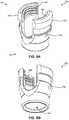
- FIG. 5Ais a top perspective view of a tulip member 500 , according to an embodiment of the present disclosure
- FIG. 5Bis a bottom perspective view of the tulip member 500 of FIG. 5A ;
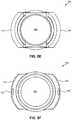
- FIG. 5Cis a front side view of the tulip member 500 of FIG. 5A ;
- FIG. 5Dis a left side view of the tulip member 500 of FIG. 5A ;
- FIG. 5Eis a top view of the tulip member 500 of FIG. 5A ;
- FIG. 5Fis a bottom view of the tulip member 500 of FIG. 5A ;
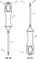
- FIG. 6Ais a perspective view of a driver tool 600 , according to an embodiment of the present disclosure.
- FIG. 6Bis a left side view of the driver tool 600 of FIG. 6A ;
- FIG. 6Cis a right side view of the driver tool 600 of FIG. 6A ;
- FIG. 6Dis a perspective view of the distal end of the driver tool 600 of FIG. 6A ;
- FIG. 6Ea bottom view of the driver tool 600 of FIG. 6A ;
- FIG. 7Ais a bone anchor system 700 including a driver tool 600 and a bone anchor assembly 100 , prior to coupling the driver tool 600 to the bone anchor assembly 100 ;
- FIG. 7Bis the bone anchor system 700 of FIG. 7A with the driver tool 600 coupled to the bone anchor assembly 100 ;
- FIG. 8is a perspective view of a straight connecting rod 800 , according to an embodiment of the present disclosure.
- FIG. 9is a perspective view of a curved connecting rod 900 , according to an embodiment of the present disclosure.
- FIG. 10is a front side view of a partial bone anchor assembly 1000 including the bone screw 200 of FIG. 2A , the collar member 300 of FIG. 3A , and the straight connecting rod 800 of FIG. 8 ;
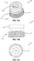
- FIG. 11Ais a top perspective view of a set screw 1100 , according to an embodiment of the present disclosure.
- FIG. 11Bis a side view of the set screw 1100 of FIG. 11A ;
- FIG. 11Cis a top view of the set screw 1100 of FIG. 11A ;
- FIG. 12is an exploded view of a bone anchor assembly 1200 , according to an embodiment of the present disclosure.
- FIG. 13is a perspective view of the bone anchor assembly 1200 of FIG. 12 , fully assembled.
- FIGS. 14A-Billustrate a flowchart of a method 1400 for implanting a bone anchor assembly, according to an embodiment of the present disclosure.
- anteriormeans toward the front of the body.
- Posteriormeans toward the back of the body.
- Superiormeans toward the head.
- Inferiormeans toward the feet.
- Medialmeans toward the midline of the body.
- Lateralmeans away from the midline of the body.
- Axialmeans toward a central axis of the body.
- Abaxialmeans away from a central axis of the body.
- Ipsilateralmeans on the same side of the body. Contralateral means on the opposite side of the body.
- a sagittal planedivides a body into right and left portions.
- a midsagittal planedivides the body into bilaterally symmetric right and left halves.
- a coronal planedivides a body into anterior and posterior portions.
- a transverse planedivides a body into superior and inferior portions.
- phrases “connected to,” “coupled to” and “in communication with”refer to any form of interaction between two or more entities, including mechanical, electrical, magnetic, electromagnetic, fluid, and thermal interaction. Two components may be functionally coupled to each other even though they are not in direct contact with each other.
- the term “abutting”refers to items that are in direct physical contact with each other, although the items may not necessarily be attached together.
- the phrase “fluid communication”refers to two features that are connected such that a fluid within one feature is able to pass into the other feature.
- FIG. 1illustrates an exploded view of a bone anchor assembly 100 , according to an embodiment of the present disclosure.
- the bone anchor assembly 100may generally include a bone screw 200 , a collar member 300 , and a tulip member 500 .
- the collar member 300 and the tulip member 500may each include grip features configured to engage and couple each of the collar member 300 and the tulip member to the head of the bone screw 200 , as will be discussed in more detail below.
- FIGS. 2A-2Cillustrate various views of a bone screw 200 , according to an embodiment of the present disclosure.
- FIG. 2Ais a side view of the bone screw 200
- FIG. 2Bis a perspective view of the bone screw 200
- FIG. 2Cis a top view of the bone screw 200 .
- the bone screw 200may generally include a proximal end 201 , a distal end 202 , a shank 210 extending between the proximal and distal ends 201 , 202 of the bone screw 200 , external threading 220 arranged along the shank 210 and configured to engage bone, as well as a bone screw head 230 coupled to the proximal end 201 of the bone screw 200 .
- the bone screw head 230may be polyaxial including a semispherical shape and one or more horizontal ridges 232 formed around a circumference of the bone screw head 230 .
- any size, shape, or style of bone screw head 230may also be used.
- the bone screw head 230may also include a driver engagement feature 240 formed in the bone screw head 230 .
- the driver engagement feature 240may have an internal hexalobular shape.
- any suitable size, shape, or style of driver engagement feature 240may also be used in conjunction with the teachings of the present disclosure.
- FIGS. 3A-3Fillustrate various views of a collar member 300 , according to an embodiment of the present disclosure.
- FIG. 3Ais a top perspective view of the collar member 300
- FIG. 3Bis a bottom perspective view of the collar member 300
- FIG. 3Cis a front side view of the collar member 300
- FIG. 3Dis a left side view of the collar member 300
- FIG. 3Eis a top view of the collar member 300
- FIG. 3Fis a bottom view of the collar member 300 .
- the collar member 300may generally include a posterior end 301 , an anterior end 302 , a first retaining arm 310 , a second retaining arm 320 , a receptacle 330 formed in the anterior end 302 of the collar member 300 , and a grip feature 340 protruding from the anterior end 302 of the collar member 300 .
- the first and second retaining arms 310 , 320may each project from the posterior end 301 of the collar member 300 on opposite sides of the posterior end 301 of the collar member 300 .
- the first retaining arm 310may include a first retaining tab 315 located on a posterior end 311 of the first retaining arm 310
- the second retaining arm 320may include a second retaining tab 325 located on a posterior end 321 of the second retaining arm 320 , opposite the first retaining tab 315 .
- the first and second retaining tabs 315 , 325may each project toward each other and into a space 370 formed between the first and second retaining arms 310 , 320 .
- first and second retaining arms 310 , 320may be resilient such that they may bend and flex away from each other when a force is applied to the first and second retaining arms 310 , 320 , as will be discussed in more detail below.
- first and second retaining arms 310 , 320may be rigid and/or substantially inflexible.
- the receptacle 330 formed in the anterior end 302 of the collar member 300may be configured to receive and engage the bone screw head 230 at any of a range of relative orientations, about multiple orthogonal axes of rotation.
- the receptacle 330may have a semispherical shape that is complementary to the shape of the bone screw head 230 .
- the receptacle 330may have any suitable size, shape, or style that may interact with any corresponding size, shape, or style of bone screw head 230 .
- the grip feature 340may be proximate the receptacle 330 and configured to engage the bone screw head 230 .
- the grip feature 340may comprise a collet structure with one or more collet arms 344 projecting from the anterior end 302 of the collar member 300 .
- the one or more collet arms 344may be resilient and/or separated from each other by one or more gaps 342 .
- the one or more collet arms 344may be arranged about the receptacle 330 and/or at least partially encircle the receptacle 330 .
- Each of the one or more collet arms 344may further include an edge 341 configured to grip the one or more horizontal ridges 232 formed in the bone screw head 230 .
- FIG. 4illustrates a partial bone anchor assembly 400 comprising the bone screw 200 coupled to the collar member 300 via the one or more collet arms 344 that project from the anterior end 302 of the collar member 300 .
- the collar member 300may include a central aperture 360 extending through the collar member 300 between the posterior and anterior ends 301 , 302 of the collar member 300 .
- the central aperture 360may be configured to receive a driver tool therethrough, as will be explained in more detail below with respect to FIGS. 7A and 7B .
- the collar member 300may also include collar depressions 350 formed in the sides of the collar member 300 proximate the first and second retaining arms 310 , 320 .
- the collar depressions 350may interact with the tulip member 500 to facilitate coupling of the tulip member 500 to the collar member 300 , as will also be discussed in more detail below with respect to FIGS. 5A-5F and 7A-7B .
- FIGS. 5A-5Fillustrate various views of a tulip member 500 , according to an embodiment of the present disclosure.
- FIG. 5Ais a top perspective view of the tulip member 500
- FIG. 5Bis a bottom perspective view of the tulip member 500
- FIG. 5Cis a front side view of the tulip member 500
- FIG. 5Dis a left side view of the tulip member 500
- FIG. 5Eis a top view of the tulip member 500
- FIG. 5Fis a bottom view of the tulip member 500 .
- the tulip member 500may generally include a posterior end 501 , an anterior end 502 , an internal bore 560 , a first tulip arm 510 , a second tulip arm 520 , and a transverse channel 570 formed between the first and second tulip arms 510 , 520 .
- the first and second tulip arms 510 , 520may each be located proximate to and/or project from the posterior end 501 of the tulip member 500 .
- the first and second tulip arms 510 , 520may be located on opposite sides of the posterior end 501 of the tulip member 500 such that a transverse channel 570 is formed between the first and second tulip arms 510 , 520 .
- the first and second tulip arms 510 , 520may be rigid.
- first and second tulip arms 510 , 520may be resilient such that they may bend and flex away from each other when a force is applied to the first and second tulip arms 510 , 520 .
- the first and second tulip arms 510 , 520may additionally include threading 580 formed in the posterior ends 511 , 521 of the first and second tulip arms 510 , 520 .
- the threading 580may be configured to receive a set screw, as will be discussed in more detail with respect to FIGS. 11A-13 .
- the internal bore 560 of the tulip member 500may extend through the tulip member 500 between the posterior and anterior ends 501 , 502 of the tulip member 500 .
- the internal bore 560may be configured to receive the collar member 300 therein.
- the internal bore 560may also be configured to receive a driver tool therethrough, as will be discussed with respect to FIGS. 7A and 7B .
- the tulip member 500may additionally include tulip depressions 550 formed in the sides of the tulip member 500 proximate the first and second tulip arms 510 , 520 .
- the tulip depressions 550may interact with the collar depressions 350 formed in the collar member 300 to couple the tulip member 500 to the collar member 300 , as shown in FIGS. 7A and 7B .
- This couplingmay be accomplished by inserting the collar member 300 into the internal bore 560 of the tulip member 500 , aligning the tulip depressions 550 with the collar depressions 350 , inserting a crimping tool (not shown) into the tulip depressions 550 , and applying a crimping force to the tulip depressions 550 with the crimping tool in order to deform the tulip depressions 550 toward each other and into the collar depressions 350 . In this manner, the deformed material of the crimped tulip depressions 550 will project inside the collar depressions 350 and couple the collar member 300 to the tulip member 500 .
- FIGS. 6A-6Fillustrate various views of a driver tool 600 , according to an embodiment of the present disclosure.
- FIG. 6Ais a perspective view of the driver tool 600
- FIG. 6Bis a left side view of the driver tool 600
- FIG. 6Cis a right side view of the driver tool 600
- FIG. 6Dis a perspective view of the distal end of the driver tool 600
- FIG. 6Ea bottom view of the driver tool 600 .
- the driver tool 600may generally include an elongate shaft 610 having a proximal end 601 and a distal end 602 , a bone screw engagement feature 630 located at the distal end 602 of the elongate shaft 610 , a handle 620 located at the proximal end 601 of the elongate shaft 610 , and a retention feature 640 .
- the bone screw engagement feature 630may be engageable with the driver engagement feature 240 formed in the bone screw head 230 in order to facilitate rotation of the bone screw 200 with the driver tool 600 .
- the bone screw engagement feature 630may have an external hexalobular shape that is complementary to the internal hexalobular shape formed in the bone screw head 230 .
- any suitable size, shape, or style of bone screw engagement feature 630 and/or driver engagement feature 240may also be used in conjunction with the teachings of the present disclosure.
- the retention feature 640may be located proximate the bone screw engagement feature 630 , located along the elongate shaft proximal to the bone screw engagement feature 630 , and/or located intermediate the bone screw engagement feature 630 and the proximal end 601 of the elongate shaft 610 .
- the retention feature 640may comprise a protrusion 640 encircling at least a portion of the elongate shaft 610 .
- the protrusion 640may have a semispherical shape with an anterior surface 642 , a posterior surface 641 , and a medial line (e.g., an equatorial line; not shown in FIG. 6D ) intermediate the posterior and anterior surfaces 641 , 642 .
- the protrusion 640may be shaped to be retained between the first retaining arm 310 and the second retaining arm 320 of the collar member 300 of the bone anchor assembly 100 .
- the posterior surface 641 of the protrusion 640may be shaped to be retained between the first retaining tab 315 located on the first retaining arm 310 of the collar member 300 , and the second retaining tab 325 (opposite the first retaining tab 315 ) located on the second retaining arm of the collar member 300 , as will be discussed with reference to FIGS. 7A and 7B below.
- FIGS. 7A and 7Billustrate a bone anchor system 700 including a driver tool 600 and a bone anchor assembly 100 , both prior to coupling the driver tool 600 to the bone anchor assembly 100 , and after the driver tool 600 has been coupled to the bone anchor assembly 100 , respectively.
- the retention feature 640is configured to removably couple the driver tool 600 to the bone anchor assembly 100 as the bone screw engagement feature 630 is moved into engagement with the driver engagement feature 240 of the bone screw 200 in the bone anchor assembly 100 .
- the driver tool 600may be removably couplable to the bone anchor assembly 100 by inserting the retention feature 640 of the driver tool 600 between the first and second retaining arms 310 , 320 of the collar member 300 , such that the retention feature 640 is retained by the first and second retaining arms 310 , 320 of the collar member 300 .
- first and second retaining tabs 315 , 325 of the first and second retaining arms 310 , 320 of the collar member 300may be configured to engage the posterior surface 641 of the retention feature 640 to removably couplable the driver tool 600 to the bone anchor assembly 100 by inserting the retention feature 640 past the first and second retaining tabs 315 , 325 and between the first and second retaining arms 310 , 320 of the collar member 300 , such that the retention feature 640 is retained by the first and second retaining tabs 315 , 325 and/or the first and second retaining arms 310 , 320 .
- This coupling procedurewill be discussed in more detail with respect to FIGS. 14A-14B below.
- FIGS. 8 and 9illustrate perspective views of an example straight connecting rod 800 and an example curved connecting rod 900 , respectively, each of which may be used in conjunction with the bone anchor assemblies of the present disclosure.
- FIG. 10shows a front side view of a partial bone anchor assembly 1000 including a bone screw 200 , a collar member 300 , and a straight connecting rod 800 .
- the first and second retaining arms 310 , 320 of the collar member 300may also be configured to provisionally retain a connecting rod 800 therebetween during assembly of the partial bone anchor assembly 1000 , in order to facilitate the implantation process.
- FIGS. 11A-11Cillustrate various views of a set screw 1100 , according to an embodiment of the present disclosure, which may be used in conjunction with the bone anchor assemblies disclosed herein.
- FIG. 11Ais a top perspective view of the set screw 1100
- FIG. 11Bis a side view of the set screw 1100
- FIG. 11Cis a top view of the set screw 1100 .
- the set screw 1100may include a proximal end 1101 , a distal end 1102 , a set screw body 1110 located toward the distal end 1102 of the set screw 1100 , a set screw head 1130 located toward the proximal end 1101 of the set screw 1100 , a set screw driver engagement feature 1140 formed in the set screw head 1130 and/or formed in the set screw body 1110 , and set screw threading 1120 arranged about the set screw body 1110 .
- the set screw 1100may be configured to engage the threading 580 of the first and second tulip arms 510 , 520 in order to rigidly couple the connecting rod 800 to the bone anchor assembly 1200 .
- FIGS. 12 and 13which respectively show an exploded view of the bone anchor assembly 1200 (including the connecting rod 800 and the set screw 1100 ), and an assembled view of the bone anchor assembly 1200 .
- the set screw head 1130may be further designed to shear off from the set screw body 1110 (not shown) when a torque force of sufficient magnitude is applied to the set screw head 1130 , relative to the set screw body 1110 , during the process of rigidly coupling the connecting rod 800 to the bone anchor assembly 1200 via the set screw 1100 .
- FIGS. 14A-Billustrate a flowchart of a method 1400 for implanting a bone anchor assembly, according to an embodiment of the present disclosure.
- the method 1400may include use of a driver tool comprising an elongate shaft having a proximal end, a distal end, a bone screw engagement feature located at the distal end of the elongate shaft, and a retention feature that is located proximal the bone screw engagement feature.
- the method 1400may also utilize a bone anchor assembly comprising a driver engagement feature.
- the method 1400may begin with a step 1410 in which the bone screw engagement feature of the driver tool may be aligned with the driver engagement feature of the bone anchor assembly.
- the driver engagement featuremay be formed in a bone screw of the bone anchor assembly.
- the method 1400may proceed to a step 1420 in which the bone screw engagement feature of the driver tool may be moved into engagement with the driver engagement feature of the bone anchor assembly.
- the method 1400may proceed to a step 1430 in which the retention feature of the driver tool may be engaged with the bone anchor assembly such that, with the bone screw engagement feature in engagement with the driver engagement feature, the retention feature may be removably coupled to the bone anchor assembly.
- the retention featuremay comprise a semispherical shape having an anterior surface and a posterior surface and the bone anchor assembly may comprise a first retaining arm having a first retaining tab and a second retaining arm having a second retaining tab, opposite the first retaining tab.
- engaging the retention feature with the bone anchor assemblymay further include: (1) engaging the anterior surface of the retention feature with the first and second retaining tabs; (2) applying an insertion force to the retention feature, relative to the first and second retaining tabs, sufficient to cause the first and second retaining arms to deflect away from each other and permit the retention feature to enter a space formed between the first and second retaining arms; and (3) inserting the retention feature between the first and second retaining arms to engage the first and second retaining tabs with the posterior surface of the retention feature and couple the driver tool to the bone anchor assembly.
- the method 1400may proceed to a step 1440 in which the bone anchor assembly (coupled to the driver tool) may be inserted into a surgical site of a patient, and the method 1400 may end. Alternatively, or in addition thereto, the method 1400 may proceed to any or all of steps 1450 - 1480 , as will be discussed below.
- the method 1400may proceed to a step 1450 in which the bone anchor assembly may be affixed to a bone of the patient at the surgical site by applying a torque force to the driver tool coupled to the bone anchor assembly.
- the method 1400may proceed to a step 1460 in which the retention feature of the driver tool may be decoupled from between the first and second retaining arms of the bone anchor assembly by pulling the driver tool proximally.
- decoupling the retention feature of the driver tool from between the first and second retaining arms of the bone anchor assemblymay include: (1) engaging the posterior surface of the retention feature with the first and second retaining tabs; (2) applying a decoupling force to the retention feature, relative to the first and second retaining tabs, sufficient to cause the first and second retaining arms to deflect away from each other and permit the retention feature to exit the space formed between the first and second retaining arms; and (3) decoupling the retention feature from between the first and second retaining arms by pulling the driver tool proximally.
- the method 1400may proceed to a step 1470 in which the driver tool may be removed from the surgical site.
- the method 1400may proceed to a step 1480 in which a connecting rod may be inserted between the first retaining arm and the second retaining arm of the bone anchor assembly in order to provisionally couple the connecting rod to the bone anchor assembly, and the method 1400 may end.
- Any methods disclosed hereincomprise one or more steps or actions for performing the described method.
- the method steps and/or actionsmay be interchanged with one another.
- the order and/or use of specific steps and/or actionsmay be modified.
Landscapes
- Health & Medical Sciences (AREA)
- Orthopedic Medicine & Surgery (AREA)
- Neurology (AREA)
- Life Sciences & Earth Sciences (AREA)
- Engineering & Computer Science (AREA)
- Biomedical Technology (AREA)
- Surgery (AREA)
- Heart & Thoracic Surgery (AREA)
- Animal Behavior & Ethology (AREA)
- General Health & Medical Sciences (AREA)
- Public Health (AREA)
- Veterinary Medicine (AREA)
- Medical Informatics (AREA)
- Nuclear Medicine, Radiotherapy & Molecular Imaging (AREA)
- Molecular Biology (AREA)
- Transplantation (AREA)
- Vascular Medicine (AREA)
- Oral & Maxillofacial Surgery (AREA)
- Cardiology (AREA)
- Physical Education & Sports Medicine (AREA)
- Surgical Instruments (AREA)
- Prostheses (AREA)
Abstract
Description
- This application claims the benefit of U.S. Provisional Patent Application No. 62/712,938 filed on Jul. 31, 2018, entitled “SPINAL SURGERY SYSTEMS AND METHODS,” the disclosure of which is incorporated herein by reference in its entirety.
- The present disclosure relates to surgical systems, methods, instruments, and devices. More specifically, the present disclosure relates to improved surgical systems, methods, instruments, and devices for implanting bone anchor assemblies in a bone of a patient.
- Spinal fixation procedures utilizing pedicle screws and rod-based fixation assemblies can be used to correct spinal conditions such as degenerative disc disease, spondylolisthesis, spinal deformities, or other spinal conditions through minimally invasive or invasive spinal surgery. For example, two or more bone anchor assemblies may be secured into bone structures of a patient's vertebrae with connecting rods secured between adjacent bone anchor assemblies in order to stabilize one or more vertebral joints of a patient. These connecting rods typically run longitudinally along the length of the patient's spine between adjacent bone anchor assemblies. However, connecting rods can be arranged in a variety of positions and/or configurations (including the use of multiple connecting rods and/or cross-bars, where desired) in view of a patient's specific anatomy and/or a specific spinal correction.
- Unfortunately, the process of implanting a bone anchor assembly with a suitable driver tool can be difficult when the bone anchor assembly is not sufficiently secured to the driver tool. Accordingly, improved surgical systems, methods, instruments, and devices that reduce or eliminate this characteristic would be desirable.
- The various systems and methods of the present disclosure have been developed in response to the present state of the art, and in particular, in response to the problems and needs in the art that have not yet been fully solved by currently available surgical instruments, devices, systems, and methods for implanting bone anchor assemblies in a patient.
- According to some embodiments, a bone anchor system may include a bone anchor assembly and a driver tool. The bone anchor assembly may include a bone screw, a collar member, and a tulip member. The bone screw may have a shank, external threading along the shank configured to engage bone, and a bone screw head coupled to a proximal end of the shank. The bone screw head may also include a driver engagement feature. The collar member may have a posterior end, an anterior end, first and second retaining arms projecting from the posterior end of the collar member, a receptacle configured to receive the bone screw head at any of a range of relative orientations, about multiple orthogonal axes of rotation, and a grip feature proximate the receptacle, the receptacle and grip feature configured to engage the bone screw head. The tulip member may include a posterior end, an anterior end, an internal bore, first and second tulip arms proximate the posterior end of the tulip member, and a transverse channel formed between the first and second tulip arms. The driver tool may include an elongate shaft having a proximal and distal ends and a bone screw engagement feature located at the distal end of the elongate shaft, such that the bone screw engagement feature is engageable with the driver engagement feature of the bone screw head to facilitate rotation of the bone screw with the driver tool. The driver tool may also include a retention feature located proximate the bone screw engagement feature. The driver tool may be removably couplable to the bone anchor assembly by inserting the retention feature between the first and second retaining arms of the collar member such that the retention feature is retained by the first and second retaining arms.
- In other embodiments, a driver tool may include an elongate shaft having proximal and distal ends, a bone screw engagement feature located at the distal end of the elongate shaft, and a retention feature located along the elongate shaft, proximal to the bone screw engagement feature. The retention feature may be configured to removably couple the driver tool to a bone anchor assembly as the bone screw engagement feature is moved into engagement with a driver engagement feature of a bone screw of the bone anchor assembly.
- In yet other embodiments, a method for implanting a bone anchor assembly through use of a driver tool having an elongate shaft having a proximal end, a distal end, a bone screw engagement feature located at the distal end of the elongate shaft, and a retention feature that is located proximal the bone screw engagement feature may include aligning the bone screw engagement feature with a driver engagement feature of the bone anchor assembly. The method may also include moving the bone screw engagement feature into engagement with the driver engagement feature, engaging the retention feature with the bone anchor assembly such that, with the bone screw engagement feature in engagement with the driver engagement feature, the retention feature is removably coupled to the bone anchor assembly, and inserting the bone anchor assembly, coupled to the driver tool, into a surgical site of a patient.
- These and other features and advantages of the present disclosure will become more fully apparent from the following description and appended claims, or may be learned by the practice of the systems and methods set forth hereinafter.
- Exemplary embodiments of the disclosure will become more fully apparent from the following description and appended claims, taken in conjunction with the accompanying drawings. Understanding that these drawings depict only exemplary embodiments and are, therefore, not to be considered limiting of the scope of the appended claims, the exemplary embodiments of the present disclosure will be described with additional specificity and detail through use of the accompanying drawings in which:
FIG. 1 is an exploded view of abone anchor assembly 100, according to an embodiment of the present disclosure;FIG. 2A is a side view of abone screw 200, according to an embodiment of the present disclosure;FIG. 2B is a perspective view of thebone screw 200 ofFIG. 2A ;FIG. 2C is a top view of thebone screw 200 ofFIG. 2A ;FIG. 3A is a top perspective view of acollar member 300, according to an embodiment of the present disclosure;FIG. 3B is a bottom perspective view of thecollar member 300 ofFIG. 3A ;FIG. 3C is a front side view of thecollar member 300 ofFIG. 3A ;FIG. 3D is a left side view of thecollar member 300 ofFIG. 3A ;FIG. 3E is a top view of thecollar member 300 ofFIG. 3A ;FIG. 3F is a bottom view of thecollar member 300 ofFIG. 3A ;FIG. 4 is a front side view of a partialbone anchor assembly 400 including thebone screw 200 ofFIG. 2A coupled to thecollar member 300 ofFIG. 3A ;FIG. 5A is a top perspective view of atulip member 500, according to an embodiment of the present disclosure;FIG. 5B is a bottom perspective view of thetulip member 500 ofFIG. 5A ;FIG. 5C is a front side view of thetulip member 500 ofFIG. 5A ;FIG. 5D is a left side view of thetulip member 500 ofFIG. 5A ;FIG. 5E is a top view of thetulip member 500 ofFIG. 5A ;FIG. 5F is a bottom view of thetulip member 500 ofFIG. 5A ;FIG. 6A is a perspective view of adriver tool 600, according to an embodiment of the present disclosure;FIG. 6B is a left side view of thedriver tool 600 ofFIG. 6A ;FIG. 6C is a right side view of thedriver tool 600 ofFIG. 6A ;FIG. 6D is a perspective view of the distal end of thedriver tool 600 ofFIG. 6A ;FIG. 6E a bottom view of thedriver tool 600 ofFIG. 6A ;FIG. 7A is abone anchor system 700 including adriver tool 600 and abone anchor assembly 100, prior to coupling thedriver tool 600 to thebone anchor assembly 100;FIG. 7B is thebone anchor system 700 ofFIG. 7A with thedriver tool 600 coupled to thebone anchor assembly 100;FIG. 8 is a perspective view of a straight connectingrod 800, according to an embodiment of the present disclosure;FIG. 9 is a perspective view of a curved connectingrod 900, according to an embodiment of the present disclosure;FIG. 10 is a front side view of a partialbone anchor assembly 1000 including thebone screw 200 ofFIG. 2A , thecollar member 300 ofFIG. 3A , and the straight connectingrod 800 ofFIG. 8 ;FIG. 11A is a top perspective view of aset screw 1100, according to an embodiment of the present disclosure;FIG. 11B is a side view of theset screw 1100 ofFIG. 11A ;FIG. 11C is a top view of theset screw 1100 ofFIG. 11A ;FIG. 12 is an exploded view of abone anchor assembly 1200, according to an embodiment of the present disclosure;FIG. 13 is a perspective view of thebone anchor assembly 1200 ofFIG. 12 , fully assembled; andFIGS. 14A-B illustrate a flowchart of amethod 1400 for implanting a bone anchor assembly, according to an embodiment of the present disclosure.- It is to be understood that the drawings are for purposes of illustrating the concepts of the disclosure and may not be drawn to scale. Furthermore, the drawings illustrate exemplary embodiments and do not represent limitations to the scope of the present disclosure.
- Exemplary embodiments of the present disclosure will be best understood by reference to the drawings, wherein like parts are designated by like numerals throughout. It will be readily understood that the components of the present disclosure, as generally described and illustrated in the Figures herein, could be arranged and designed in a wide variety of different configurations. Thus, the following more detailed description of the embodiments of the apparatus and method, as represented in the Figures, is not intended to limit the scope of the present disclosure, as claimed in this or any other application claiming priority to this application, but is merely representative of exemplary embodiments of the present disclosure.
- Standard medical directions, planes of reference, and descriptive terminology are employed in this specification. For example, anterior means toward the front of the body. Posterior means toward the back of the body. Superior means toward the head. Inferior means toward the feet. Medial means toward the midline of the body. Lateral means away from the midline of the body. Axial means toward a central axis of the body. Abaxial means away from a central axis of the body. Ipsilateral means on the same side of the body. Contralateral means on the opposite side of the body. A sagittal plane divides a body into right and left portions. A midsagittal plane divides the body into bilaterally symmetric right and left halves. A coronal plane divides a body into anterior and posterior portions. A transverse plane divides a body into superior and inferior portions. These descriptive terms may be applied to an animate or inanimate body.
- The phrases “connected to,” “coupled to” and “in communication with” refer to any form of interaction between two or more entities, including mechanical, electrical, magnetic, electromagnetic, fluid, and thermal interaction. Two components may be functionally coupled to each other even though they are not in direct contact with each other. The term “abutting” refers to items that are in direct physical contact with each other, although the items may not necessarily be attached together. The phrase “fluid communication” refers to two features that are connected such that a fluid within one feature is able to pass into the other feature.
- The word “exemplary” is used herein to mean “serving as an example, instance, or illustration.” Any embodiment described herein as “exemplary” is not necessarily to be construed as preferred or advantageous over other embodiments. While the various aspects of the embodiments are presented in drawings, the drawings are not necessarily drawn to scale unless specifically indicated.
FIG. 1 illustrates an exploded view of abone anchor assembly 100, according to an embodiment of the present disclosure. Thebone anchor assembly 100 may generally include abone screw 200, acollar member 300, and atulip member 500. Thecollar member 300 and thetulip member 500 may each include grip features configured to engage and couple each of thecollar member 300 and the tulip member to the head of thebone screw 200, as will be discussed in more detail below.FIGS. 2A-2C illustrate various views of abone screw 200, according to an embodiment of the present disclosure. Specifically,FIG. 2A is a side view of thebone screw 200;FIG. 2B is a perspective view of thebone screw 200; andFIG. 2C is a top view of thebone screw 200. Thebone screw 200 may generally include aproximal end 201, adistal end 202, ashank 210 extending between the proximal anddistal ends bone screw 200,external threading 220 arranged along theshank 210 and configured to engage bone, as well as abone screw head 230 coupled to theproximal end 201 of thebone screw 200.- In at least one embodiment, the
bone screw head 230 may be polyaxial including a semispherical shape and one or morehorizontal ridges 232 formed around a circumference of thebone screw head 230. However, it will be understood that any size, shape, or style ofbone screw head 230 may also be used. - The
bone screw head 230 may also include adriver engagement feature 240 formed in thebone screw head 230. In at least one embodiment, thedriver engagement feature 240 may have an internal hexalobular shape. However, it will be understood that any suitable size, shape, or style ofdriver engagement feature 240 may also be used in conjunction with the teachings of the present disclosure. FIGS. 3A-3F illustrate various views of acollar member 300, according to an embodiment of the present disclosure. Specifically,FIG. 3A is a top perspective view of thecollar member 300;FIG. 3B is a bottom perspective view of thecollar member 300;FIG. 3C is a front side view of thecollar member 300;FIG. 3D is a left side view of thecollar member 300;FIG. 3E is a top view of thecollar member 300; andFIG. 3F is a bottom view of thecollar member 300. Thecollar member 300 may generally include aposterior end 301, ananterior end 302, afirst retaining arm 310, asecond retaining arm 320, areceptacle 330 formed in theanterior end 302 of thecollar member 300, and agrip feature 340 protruding from theanterior end 302 of thecollar member 300.- The first and second retaining
arms posterior end 301 of thecollar member 300 on opposite sides of theposterior end 301 of thecollar member 300. Thefirst retaining arm 310 may include afirst retaining tab 315 located on aposterior end 311 of thefirst retaining arm 310, and thesecond retaining arm 320 may include asecond retaining tab 325 located on aposterior end 321 of thesecond retaining arm 320, opposite thefirst retaining tab 315. The first and second retainingtabs space 370 formed between the first and second retainingarms arms arms arms - The
receptacle 330 formed in theanterior end 302 of thecollar member 300 may be configured to receive and engage thebone screw head 230 at any of a range of relative orientations, about multiple orthogonal axes of rotation. In at least one embodiment, thereceptacle 330 may have a semispherical shape that is complementary to the shape of thebone screw head 230. However, it will be understood that thereceptacle 330 may have any suitable size, shape, or style that may interact with any corresponding size, shape, or style ofbone screw head 230. - The
grip feature 340 may be proximate thereceptacle 330 and configured to engage thebone screw head 230. In at least one embodiment, thegrip feature 340 may comprise a collet structure with one ormore collet arms 344 projecting from theanterior end 302 of thecollar member 300. The one ormore collet arms 344 may be resilient and/or separated from each other by one ormore gaps 342. The one ormore collet arms 344 may be arranged about thereceptacle 330 and/or at least partially encircle thereceptacle 330. Each of the one ormore collet arms 344 may further include anedge 341 configured to grip the one or morehorizontal ridges 232 formed in thebone screw head 230. In this manner, thecollar member 300 may engage thebone screw head 230 at any of a range of relative orientations, about multiple orthogonal axes of rotation. For example,FIG. 4 illustrates a partialbone anchor assembly 400 comprising thebone screw 200 coupled to thecollar member 300 via the one ormore collet arms 344 that project from theanterior end 302 of thecollar member 300. - The
collar member 300 may include acentral aperture 360 extending through thecollar member 300 between the posterior and anterior ends301,302 of thecollar member 300. Thecentral aperture 360 may be configured to receive a driver tool therethrough, as will be explained in more detail below with respect toFIGS. 7A and 7B . - The
collar member 300 may also includecollar depressions 350 formed in the sides of thecollar member 300 proximate the first and second retainingarms tulip member 500 to facilitate coupling of thetulip member 500 to thecollar member 300, as will also be discussed in more detail below with respect toFIGS. 5A-5F and 7A-7B . FIGS. 5A-5F illustrate various views of atulip member 500, according to an embodiment of the present disclosure. Specifically,FIG. 5A is a top perspective view of thetulip member 500;FIG. 5B is a bottom perspective view of thetulip member 500;FIG. 5C is a front side view of thetulip member 500;FIG. 5D is a left side view of thetulip member 500;FIG. 5E is a top view of thetulip member 500; andFIG. 5F is a bottom view of thetulip member 500. Thetulip member 500 may generally include aposterior end 501, ananterior end 502, aninternal bore 560, afirst tulip arm 510, asecond tulip arm 520, and atransverse channel 570 formed between the first andsecond tulip arms - The first and
second tulip arms posterior end 501 of thetulip member 500. The first andsecond tulip arms posterior end 501 of thetulip member 500 such that atransverse channel 570 is formed between the first andsecond tulip arms second tulip arms second tulip arms second tulip arms second tulip arms second tulip arms FIGS. 11A-13 . - The
internal bore 560 of thetulip member 500 may extend through thetulip member 500 between the posterior and anterior ends501,502 of thetulip member 500. Theinternal bore 560 may be configured to receive thecollar member 300 therein. Theinternal bore 560 may also be configured to receive a driver tool therethrough, as will be discussed with respect toFIGS. 7A and 7B . - The
tulip member 500 may additionally includetulip depressions 550 formed in the sides of thetulip member 500 proximate the first andsecond tulip arms collar depressions 350 formed in thecollar member 300 to couple thetulip member 500 to thecollar member 300, as shown inFIGS. 7A and 7B . This coupling may be accomplished by inserting thecollar member 300 into theinternal bore 560 of thetulip member 500, aligning thetulip depressions 550 with thecollar depressions 350, inserting a crimping tool (not shown) into thetulip depressions 550, and applying a crimping force to thetulip depressions 550 with the crimping tool in order to deform thetulip depressions 550 toward each other and into thecollar depressions 350. In this manner, the deformed material of the crimpedtulip depressions 550 will project inside thecollar depressions 350 and couple thecollar member 300 to thetulip member 500. FIGS. 6A-6F illustrate various views of adriver tool 600, according to an embodiment of the present disclosure. Specifically,FIG. 6A is a perspective view of thedriver tool 600;FIG. 6B is a left side view of thedriver tool 600;FIG. 6C is a right side view of thedriver tool 600;FIG. 6D is a perspective view of the distal end of thedriver tool 600; andFIG. 6E a bottom view of thedriver tool 600. Thedriver tool 600 may generally include anelongate shaft 610 having aproximal end 601 and adistal end 602, a bonescrew engagement feature 630 located at thedistal end 602 of theelongate shaft 610, ahandle 620 located at theproximal end 601 of theelongate shaft 610, and aretention feature 640.- The bone
screw engagement feature 630 may be engageable with thedriver engagement feature 240 formed in thebone screw head 230 in order to facilitate rotation of thebone screw 200 with thedriver tool 600. In at least one embodiment, the bonescrew engagement feature 630 may have an external hexalobular shape that is complementary to the internal hexalobular shape formed in thebone screw head 230. However, it will be understood that any suitable size, shape, or style of bonescrew engagement feature 630 and/ordriver engagement feature 240 may also be used in conjunction with the teachings of the present disclosure. - The
retention feature 640 may be located proximate the bonescrew engagement feature 630, located along the elongate shaft proximal to the bonescrew engagement feature 630, and/or located intermediate the bonescrew engagement feature 630 and theproximal end 601 of theelongate shaft 610. In at least one embodiment, theretention feature 640 may comprise aprotrusion 640 encircling at least a portion of theelongate shaft 610. Theprotrusion 640 may have a semispherical shape with ananterior surface 642, aposterior surface 641, and a medial line (e.g., an equatorial line; not shown inFIG. 6D ) intermediate the posterior andanterior surfaces protrusion 640 may be shaped to be retained between thefirst retaining arm 310 and thesecond retaining arm 320 of thecollar member 300 of thebone anchor assembly 100. In a particular embodiment, theposterior surface 641 of theprotrusion 640 may be shaped to be retained between thefirst retaining tab 315 located on thefirst retaining arm 310 of thecollar member 300, and the second retaining tab325 (opposite the first retaining tab315) located on the second retaining arm of thecollar member 300, as will be discussed with reference toFIGS. 7A and 7B below. FIGS. 7A and 7B illustrate abone anchor system 700 including adriver tool 600 and abone anchor assembly 100, both prior to coupling thedriver tool 600 to thebone anchor assembly 100, and after thedriver tool 600 has been coupled to thebone anchor assembly 100, respectively. In general, theretention feature 640 is configured to removably couple thedriver tool 600 to thebone anchor assembly 100 as the bonescrew engagement feature 630 is moved into engagement with thedriver engagement feature 240 of thebone screw 200 in thebone anchor assembly 100.- In at least one embodiment, the
driver tool 600 may be removably couplable to thebone anchor assembly 100 by inserting theretention feature 640 of thedriver tool 600 between the first and second retainingarms collar member 300, such that theretention feature 640 is retained by the first and second retainingarms collar member 300. - In a particular embodiment, the first and second retaining
tabs arms collar member 300 may be configured to engage theposterior surface 641 of theretention feature 640 to removably couplable thedriver tool 600 to thebone anchor assembly 100 by inserting theretention feature 640 past the first and second retainingtabs arms collar member 300, such that theretention feature 640 is retained by the first and second retainingtabs arms FIGS. 14A-14B below. FIGS. 8 and 9 illustrate perspective views of an example straight connectingrod 800 and an example curved connectingrod 900, respectively, each of which may be used in conjunction with the bone anchor assemblies of the present disclosure. However, it will be understood that other connecting rods of any suitable size, shape, or style may also be used in conjunction with the bone anchor assemblies disclosed herein.FIG. 10 shows a front side view of a partialbone anchor assembly 1000 including abone screw 200, acollar member 300, and a straight connectingrod 800. In this manner, the first and second retainingarms collar member 300 may also be configured to provisionally retain a connectingrod 800 therebetween during assembly of the partialbone anchor assembly 1000, in order to facilitate the implantation process.FIGS. 11A-11C illustrate various views of aset screw 1100, according to an embodiment of the present disclosure, which may be used in conjunction with the bone anchor assemblies disclosed herein. Specifically,FIG. 11A is a top perspective view of theset screw 1100;FIG. 11B is a side view of theset screw 1100; andFIG. 11C is a top view of theset screw 1100. In general, theset screw 1100 may include aproximal end 1101, adistal end 1102, aset screw body 1110 located toward thedistal end 1102 of theset screw 1100, aset screw head 1130 located toward theproximal end 1101 of theset screw 1100, a set screwdriver engagement feature 1140 formed in theset screw head 1130 and/or formed in theset screw body 1110, and set screw threading1120 arranged about theset screw body 1110.- The
set screw 1100 may be configured to engage the threading580 of the first andsecond tulip arms rod 800 to thebone anchor assembly 1200. This is best seen inFIGS. 12 and 13 , which respectively show an exploded view of the bone anchor assembly1200 (including the connectingrod 800 and the set screw1100), and an assembled view of thebone anchor assembly 1200. - In at least one embodiment, the
set screw head 1130 may be further designed to shear off from the set screw body1110 (not shown) when a torque force of sufficient magnitude is applied to theset screw head 1130, relative to theset screw body 1110, during the process of rigidly coupling the connectingrod 800 to thebone anchor assembly 1200 via theset screw 1100. FIGS. 14A-B illustrate a flowchart of amethod 1400 for implanting a bone anchor assembly, according to an embodiment of the present disclosure. In general, themethod 1400 may include use of a driver tool comprising an elongate shaft having a proximal end, a distal end, a bone screw engagement feature located at the distal end of the elongate shaft, and a retention feature that is located proximal the bone screw engagement feature. Themethod 1400 may also utilize a bone anchor assembly comprising a driver engagement feature.- The
method 1400 may begin with astep 1410 in which the bone screw engagement feature of the driver tool may be aligned with the driver engagement feature of the bone anchor assembly. In at least one embodiment, the driver engagement feature may be formed in a bone screw of the bone anchor assembly. - Once the bone screw engagement feature of the driver tool has been aligned with the driver engagement feature of the bone anchor assembly, the
method 1400 may proceed to astep 1420 in which the bone screw engagement feature of the driver tool may be moved into engagement with the driver engagement feature of the bone anchor assembly. - Once the bone screw engagement feature of the driver tool has been moved into engagement with the driver engagement feature of the bone anchor assembly, the
method 1400 may proceed to astep 1430 in which the retention feature of the driver tool may be engaged with the bone anchor assembly such that, with the bone screw engagement feature in engagement with the driver engagement feature, the retention feature may be removably coupled to the bone anchor assembly. - In a particular embodiment, the retention feature may comprise a semispherical shape having an anterior surface and a posterior surface and the bone anchor assembly may comprise a first retaining arm having a first retaining tab and a second retaining arm having a second retaining tab, opposite the first retaining tab. In this embodiment, engaging the retention feature with the bone anchor assembly may further include: (1) engaging the anterior surface of the retention feature with the first and second retaining tabs; (2) applying an insertion force to the retention feature, relative to the first and second retaining tabs, sufficient to cause the first and second retaining arms to deflect away from each other and permit the retention feature to enter a space formed between the first and second retaining arms; and (3) inserting the retention feature between the first and second retaining arms to engage the first and second retaining tabs with the posterior surface of the retention feature and couple the driver tool to the bone anchor assembly.
- Once the retention feature of the driver tool has be engaged with the bone anchor assembly to removably couple the driver tool to the bone anchor assembly, the
method 1400 may proceed to astep 1440 in which the bone anchor assembly (coupled to the driver tool) may be inserted into a surgical site of a patient, and themethod 1400 may end. Alternatively, or in addition thereto, themethod 1400 may proceed to any or all of steps1450-1480, as will be discussed below. - Once the bone anchor assembly (coupled to the driver tool) has been inserted into the surgical site of the patient, the
method 1400 may proceed to astep 1450 in which the bone anchor assembly may be affixed to a bone of the patient at the surgical site by applying a torque force to the driver tool coupled to the bone anchor assembly. - Once the bone anchor assembly has been affixed to the bone of the patient, the
method 1400 may proceed to astep 1460 in which the retention feature of the driver tool may be decoupled from between the first and second retaining arms of the bone anchor assembly by pulling the driver tool proximally. - In a particular embodiment, decoupling the retention feature of the driver tool from between the first and second retaining arms of the bone anchor assembly may include: (1) engaging the posterior surface of the retention feature with the first and second retaining tabs; (2) applying a decoupling force to the retention feature, relative to the first and second retaining tabs, sufficient to cause the first and second retaining arms to deflect away from each other and permit the retention feature to exit the space formed between the first and second retaining arms; and (3) decoupling the retention feature from between the first and second retaining arms by pulling the driver tool proximally.
- Once the retention feature of the driver tool has been decoupled from between the first and second retaining arms of the bone anchor assembly, the
method 1400 may proceed to astep 1470 in which the driver tool may be removed from the surgical site. - Once the driver tool has been removed from the surgical site, the
method 1400 may proceed to astep 1480 in which a connecting rod may be inserted between the first retaining arm and the second retaining arm of the bone anchor assembly in order to provisionally couple the connecting rod to the bone anchor assembly, and themethod 1400 may end. - Any methods disclosed herein comprise one or more steps or actions for performing the described method. The method steps and/or actions may be interchanged with one another. In other words, unless a specific order of steps or actions is required for proper operation of the embodiment, the order and/or use of specific steps and/or actions may be modified.
- Reference throughout this specification to “an embodiment” or “the embodiment” means that a particular feature, structure or characteristic described in connection with that embodiment is included in at least one embodiment. Thus, the quoted phrases, or variations thereof, as recited throughout this specification are not necessarily all referring to the same embodiment.
- Similarly, it should be appreciated that in the above description of embodiments, various features are sometimes grouped together in a single embodiment, Figure, or description thereof for the purpose of streamlining the disclosure. This method of disclosure, however, is not to be interpreted as reflecting an intention that any claim requires more features than those expressly recited in that claim. Rather, as the following claims reflect, inventive aspects lie in a combination of fewer than all features of any single foregoing disclosed embodiment. Thus, the claims following this Detailed Description are hereby expressly incorporated into this Detailed Description, with each claim standing on its own as a separate embodiment. This disclosure includes all permutations of the independent claims with their dependent claims.
- Recitation in the claims of the term “first” with respect to a feature or element does not necessarily imply the existence of a second or additional such feature or element. Elements recited in means-plus-function format are intended to be construed in accordance with 35 U.S.C. § 112 Para. 6. It will be apparent to those having skill in the art that changes may be made to the details of the above-described embodiments without departing from the underlying principles set forth herein.
- While specific embodiments and applications of the present disclosure have been illustrated and described, it is to be understood that the scope of the appended claims is not limited to the precise configuration and components disclosed herein. Various modifications, changes, and variations which will be apparent to those skilled in the art may be made in the arrangement, operation, and details of the methods and systems disclosed herein.
Claims (20)
Priority Applications (5)
| Application Number | Priority Date | Filing Date | Title |
|---|---|---|---|
| US16/434,976US11540863B2 (en) | 2018-07-31 | 2019-06-07 | Spinal surgery systems and methods |
| PCT/US2019/044429WO2020028536A1 (en) | 2018-07-31 | 2019-07-31 | Spinal surgery systems |
| JP2021505755AJP2021533857A (en) | 2018-07-31 | 2019-07-31 | Spine surgery system and method |
| AU2019315504AAU2019315504A1 (en) | 2018-07-31 | 2019-07-31 | Spinal surgery systems |
| EP19752842.5AEP3829466B1 (en) | 2018-07-31 | 2019-07-31 | Spinal surgery systems |
Applications Claiming Priority (2)
| Application Number | Priority Date | Filing Date | Title |
|---|---|---|---|
| US201862712938P | 2018-07-31 | 2018-07-31 | |
| US16/434,976US11540863B2 (en) | 2018-07-31 | 2019-06-07 | Spinal surgery systems and methods |
Publications (2)
| Publication Number | Publication Date |
|---|---|
| US20200038064A1true US20200038064A1 (en) | 2020-02-06 |
| US11540863B2 US11540863B2 (en) | 2023-01-03 |
Family
ID=69228116
Family Applications (2)
| Application Number | Title | Priority Date | Filing Date |
|---|---|---|---|
| US16/435,128Active2039-11-09US11311314B2 (en) | 2018-07-31 | 2019-06-07 | Spinal surgery systems and methods |
| US16/434,976ActiveUS11540863B2 (en) | 2018-07-31 | 2019-06-07 | Spinal surgery systems and methods |
Family Applications Before (1)
| Application Number | Title | Priority Date | Filing Date |
|---|---|---|---|
| US16/435,128Active2039-11-09US11311314B2 (en) | 2018-07-31 | 2019-06-07 | Spinal surgery systems and methods |
Country Status (5)
| Country | Link |
|---|---|
| US (2) | US11311314B2 (en) |
| EP (2) | EP3829493B1 (en) |
| JP (2) | JP2021533857A (en) |
| AU (2) | AU2019314431A1 (en) |
| WO (2) | WO2020028536A1 (en) |
Cited By (6)
| Publication number | Priority date | Publication date | Assignee | Title |
|---|---|---|---|---|
| US11291477B1 (en) | 2021-05-04 | 2022-04-05 | Warsaw Orthopedic, Inc. | Dorsal adjusting implant and methods of use |
| US11432848B1 (en) | 2021-05-12 | 2022-09-06 | Warsaw Orthopedic, Inc. | Top loading quick lock construct |
| US11627998B2 (en) | 2020-12-11 | 2023-04-18 | Warsaw Orthopedic, Inc. | Head position and driver combination instrument |
| US11712270B2 (en) | 2021-05-17 | 2023-08-01 | Warsaw Orthopedic, Inc. | Quick lock clamp constructs and associated methods |
| US11957391B2 (en) | 2021-11-01 | 2024-04-16 | Warsaw Orthopedic, Inc. | Bone screw having an overmold of a shank |
| US12004782B2 (en) | 2020-03-26 | 2024-06-11 | Warsaw Orthopedic, Inc. | Instrument for locking orthopedic screws |
Families Citing this family (1)
| Publication number | Priority date | Publication date | Assignee | Title |
|---|---|---|---|---|
| US8858637B2 (en)* | 2010-09-30 | 2014-10-14 | Stryker Spine | Surgical implant with guiding rail |
Family Cites Families (149)
| Publication number | Priority date | Publication date | Assignee | Title |
|---|---|---|---|---|
| US2905178A (en) | 1955-12-20 | 1959-09-22 | Iii Paul Hilzinger | Surgical control device for controlling operating means inserted into a body cavity |
| USRE28111E (en) | 1971-01-04 | 1974-08-13 | Fastener with improved threadconstruction | |
| US3861269A (en) | 1971-01-04 | 1975-01-21 | Superior Dry Wall Screw Mfg Co | Fastener with improved thread construction |
| US3703843A (en) | 1971-01-04 | 1972-11-28 | Msl Ind Inc | Fastener with improved thread construction |
| US3681840A (en) | 1971-04-28 | 1972-08-08 | Lisle Corp | Reversible pliers |
| US4268253A (en) | 1979-12-26 | 1981-05-19 | Gross Michael J | Dowel post for dental and medical prosthetic devices |
| IT1237496B (en) | 1989-10-26 | 1993-06-08 | Giuseppe Vrespa | SCREW DEVICE FOR ANCHORING BONE PROSTHESES, METHOD FOR THE APPLICATION OF SUCH DEVICE AND RELATED EQUIPMENT |
| FR2681776A1 (en) | 1991-09-30 | 1993-04-02 | Fixano Sa | VERTEBRAL OSTEOSYNTHESIS DEVICE. |
| US5246442A (en) | 1991-12-31 | 1993-09-21 | Danek Medical, Inc. | Spinal hook |
| US5405328A (en) | 1992-06-17 | 1995-04-11 | Minnesota Mining And Manufacturing Company | Trocar with replaceable obturator |
| US5269686A (en) | 1993-05-10 | 1993-12-14 | James Robert A | Threaded drivable dental implant |
| US6629984B1 (en) | 1998-07-07 | 2003-10-07 | Kwan-Ho Chan | Surgical repair kit and its method of use |
| AU696765B2 (en) | 1994-08-29 | 1998-09-17 | Societe De Fabrication De Materiel Orthopedique - Sofamor | Osteosynthesis instrument |
| US5601553A (en) | 1994-10-03 | 1997-02-11 | Synthes (U.S.A.) | Locking plate and bone screw |
| DE19509332C1 (en) | 1995-03-15 | 1996-08-14 | Harms Juergen | Anchoring element |
| US6193719B1 (en) | 1995-08-24 | 2001-02-27 | Sofamor S.N.C. | Threaded clamping plug for interconnecting two implants of a spinal osteosynthesis instrumentation or other implants |
| US5697929A (en) | 1995-10-18 | 1997-12-16 | Cross Medical Products, Inc. | Self-limiting set screw for use with spinal implant systems |
| US5879350A (en) | 1996-09-24 | 1999-03-09 | Sdgi Holdings, Inc. | Multi-axial bone screw assembly |
| US5797911A (en) | 1996-09-24 | 1998-08-25 | Sdgi Holdings, Inc. | Multi-axial bone screw assembly |
| US5885286A (en) | 1996-09-24 | 1999-03-23 | Sdgi Holdings, Inc. | Multi-axial bone screw assembly |
| EP0934026B1 (en) | 1996-10-24 | 2009-07-15 | Zimmer Spine Austin, Inc | Apparatus for spinal fixation |
| US6416515B1 (en) | 1996-10-24 | 2002-07-09 | Spinal Concepts, Inc. | Spinal fixation system |
| US5728098A (en) | 1996-11-07 | 1998-03-17 | Sdgi Holdings, Inc. | Multi-angle bone screw assembly using shape-memory technology |
| US6004349A (en) | 1997-01-06 | 1999-12-21 | Jackson; Roger P. | Set screw for use with osteosynthesis apparatus |
| US6021343A (en) | 1997-11-20 | 2000-02-01 | Surgical Navigation Technologies | Image guided awl/tap/screwdriver |
| US6010503A (en) | 1998-04-03 | 2000-01-04 | Spinal Innovations, Llc | Locking mechanism |
| DE19832303C2 (en)* | 1998-07-17 | 2000-05-18 | Storz Karl Gmbh & Co Kg | screwdriver |
| WO2000015125A1 (en) | 1998-09-11 | 2000-03-23 | Synthes Ag Chur | Variable angle spinal fixation system |
| AU760821B2 (en) | 1998-10-02 | 2003-05-22 | Synthes Gmbh | Spinal disc space distractor |
| US6296642B1 (en) | 1998-11-09 | 2001-10-02 | Sdgi Holdings, Inc. | Reverse angle thread for preventing splaying in medical devices |
| US6216570B1 (en) | 1999-01-05 | 2001-04-17 | L. Vad Technology, Inc. | Driver for captively holding a fastener during assembly and disassembly of two parts |
| US6045312A (en) | 1999-03-17 | 2000-04-04 | Illinois Tool Works Inc. | Fastener having primary and secondary threads |
| GB2348390B (en) | 1999-03-24 | 2003-06-04 | Stephen Michael Radley Young | Interchangable handles |
| US6273888B1 (en) | 1999-05-28 | 2001-08-14 | Sdgi Holdings, Inc. | Device and method for selectively preventing the locking of a shape-memory alloy coupling system |
| US6254602B1 (en) | 1999-05-28 | 2001-07-03 | Sdgi Holdings, Inc. | Advanced coupling device using shape-memory technology |
| US6257105B1 (en) | 1999-12-20 | 2001-07-10 | Shuh-Sen Lin | Reversible jaw snap ring pliers |
| US6743233B1 (en) | 2000-08-02 | 2004-06-01 | Orthopaedic Biosystems, Ltd., Inc. | Medical screw and method of installation |
| US6679886B2 (en) | 2000-09-01 | 2004-01-20 | Synthes (Usa) | Tools and methods for creating cavities in bone |
| EP1219255B1 (en) | 2000-12-27 | 2003-10-15 | BIEDERMANN MOTECH GmbH | Screw for connection to a rod |
| US6488681B2 (en) | 2001-01-05 | 2002-12-03 | Stryker Spine S.A. | Pedicle screw assembly |
| US6834571B1 (en) | 2001-06-04 | 2004-12-28 | Joseph T. Lowe | Dual headed pliers with pommeled handles |
| SE0102749D0 (en) | 2001-08-15 | 2001-08-15 | Astra Tech Ab | Implant, arrangement including an implant, and method of inserting said implant into bone tissue |
| US20030060714A1 (en) | 2001-09-24 | 2003-03-27 | Henderson Richard W. | Medical ultrasound transducer with interchangeable handle |
| DE10157969C1 (en) | 2001-11-27 | 2003-02-06 | Biedermann Motech Gmbh | Element used in spinal and accident surgery comprises a shaft joined to a holding element having a U-shaped recess with two free arms having an internal thread with flanks lying at right angles to the central axis of the holding element |
| DE10164323C1 (en) | 2001-12-28 | 2003-06-18 | Biedermann Motech Gmbh | Bone screw has holder element joined to shaft and possessing two free arms , with inner screw, slot, external nut, cavity and shoulder cooperating with attachment |
| US6660006B2 (en) | 2002-04-17 | 2003-12-09 | Stryker Spine | Rod persuader |
| US7842073B2 (en) | 2002-04-18 | 2010-11-30 | Aesculap Ii, Inc. | Screw and rod fixation assembly and device |
| US6740086B2 (en) | 2002-04-18 | 2004-05-25 | Spinal Innovations, Llc | Screw and rod fixation assembly and device |
| US7278995B2 (en) | 2002-06-04 | 2007-10-09 | Howmedica Osteonics Corp. | Apparatus for securing a spinal rod system |
| AU2003287273C1 (en)* | 2002-10-30 | 2010-01-07 | Zimmer Spine, Inc. | Spinal stabilization system insertion and methods |
| DE10310540B3 (en) | 2003-03-11 | 2004-08-19 | Biedermann Motech Gmbh | Anchoring element for bone or spinal column surgery has threaded shaft and cylindrical reception part for coupling with rod having U-shaped seating with screw threads at ends of its arms |
| US7645232B2 (en) | 2003-05-16 | 2010-01-12 | Zimmer Spine, Inc. | Access device for minimally invasive surgery |
| US7087057B2 (en) | 2003-06-27 | 2006-08-08 | Depuy Acromed, Inc. | Polyaxial bone screw |
| US9393039B2 (en) | 2003-12-17 | 2016-07-19 | Brainlab Ag | Universal instrument or instrument set for computer guided surgery |
| US20050234481A1 (en) | 2004-03-31 | 2005-10-20 | Wilson-Cook Medical Inc. | Suture cutting device |
| US7572281B2 (en) | 2004-08-06 | 2009-08-11 | Depuy Spine, Inc. | Instrument for guiding a rod into an implant in a spinal fixation system |
| US7666189B2 (en) | 2004-09-29 | 2010-02-23 | Synthes Usa, Llc | Less invasive surgical system and methods |
| US7794477B2 (en) | 2004-10-05 | 2010-09-14 | Warsaw Orthopedic, Inc. | Spinal implants and methods with extended multi-axial anchor assemblies |
| US7655014B2 (en) | 2004-12-06 | 2010-02-02 | Cameron Health, Inc. | Apparatus and method for subcutaneous electrode insertion |
| US7445627B2 (en) | 2005-01-31 | 2008-11-04 | Alpinespine, Llc | Polyaxial pedicle screw assembly |
| US7677891B2 (en) | 2005-02-01 | 2010-03-16 | Implant Direct Int'l, Inc. | Tapered endosseous dental implants with external multiple lead threads |
| US7476239B2 (en) | 2005-05-10 | 2009-01-13 | Jackson Roger P | Polyaxial bone screw with compound articulation |
| US8668699B2 (en) | 2005-04-14 | 2014-03-11 | Warsaw Orthopedic, Inc. | Multi-function orthopedic instrument |
| US7575580B2 (en)* | 2005-04-15 | 2009-08-18 | Warsaw Orthopedic, Inc. | Instruments, implants and methods for positioning implants into a spinal disc space |
| WO2007038654A2 (en) | 2005-09-26 | 2007-04-05 | Pioneer Surgical Technology, Inc. | Apparatus and method for implantation of surgical devices |
| US20070213737A1 (en) | 2006-03-08 | 2007-09-13 | Seaspine, Inc. | Insertion tool for an intervertebral spacer providing multiple angles of insertion |
| EP1998720B1 (en)* | 2006-03-22 | 2021-05-12 | Alphaspine, Inc. | Pivotable interbody spacer |
| CA2647026A1 (en) | 2006-03-22 | 2008-08-28 | Pioneer Surgical Technology, Inc. | Low top bone fixation system and method for using the same |
| US9345587B2 (en) | 2006-03-22 | 2016-05-24 | Beacon Biomedical, Llc | Pivotal lateral cage and method of insertion |
| US20070260314A1 (en) | 2006-05-02 | 2007-11-08 | Ashok Biyani | Transforaminal lumbar interbody fusion cage |
| US20080027544A1 (en) | 2006-07-28 | 2008-01-31 | Warsaw Orthopedic Inc. | Instruments and techniques for engaging spinal implants for insertion into a spinal space |
| US8512344B2 (en) | 2006-08-16 | 2013-08-20 | Pioneer Surgical Technology, Inc. | Insertion instrument for a spinal fixation system |
| WO2008022318A2 (en)* | 2006-08-17 | 2008-02-21 | Synthes (U.S.A) | Push-off driver and method for inserting bone screws |
| US8506636B2 (en) | 2006-09-08 | 2013-08-13 | Theken Spine, Llc | Offset radius lordosis |
| US8162990B2 (en) | 2006-11-16 | 2012-04-24 | Spine Wave, Inc. | Multi-axial spinal fixation system |
| US9039768B2 (en) | 2006-12-22 | 2015-05-26 | Medos International Sarl | Composite vertebral spacers and instrument |
| US8231635B2 (en) | 2007-01-18 | 2012-07-31 | Stryker Spine | Polyaxial screwdriver for a pedicle screw system |
| US8043343B2 (en)* | 2007-06-28 | 2011-10-25 | Zimmer Spine, Inc. | Stabilization system and method |
| PL2170192T3 (en) | 2007-07-20 | 2011-07-29 | Synthes Gmbh | Polyaxial bone fixation element |
| WO2009040840A1 (en) | 2007-09-28 | 2009-04-02 | Sintea Biotech S.P.A. | Intersomatic cage, pliers for intersomatic cage, kit for insertion of an intersomatic cage |
| US8241294B2 (en) | 2007-12-19 | 2012-08-14 | Depuy Spine, Inc. | Instruments for expandable corpectomy spinal fusion cage |
| US20110046637A1 (en) | 2008-01-14 | 2011-02-24 | The University Of Western Ontario | Sensorized medical instrument |
| EP2237748B1 (en) | 2008-01-17 | 2012-09-05 | Synthes GmbH | An expandable intervertebral implant |
| US8235997B2 (en) | 2008-01-29 | 2012-08-07 | Pioneer Surgical Technology, Inc. | Rod locking instrument |
| US8088163B1 (en) | 2008-02-06 | 2012-01-03 | Kleiner Jeffrey B | Tools and methods for spinal fusion |
| US8226656B2 (en) | 2008-04-16 | 2012-07-24 | Warsaw Orthopedic, Inc. | Minimally invasive systems and methods for insertion of a connecting member adjacent the spinal column |
| US20090264895A1 (en)* | 2008-04-22 | 2009-10-22 | Warsaw Orthopedic, Inc. | Systems and methods for implanting a bone fastener and delivering a bone filling material |
| US9333086B2 (en) | 2008-06-06 | 2016-05-10 | Providence Medical Technology, Inc. | Spinal facet cage implant |
| US8920424B2 (en) | 2008-06-11 | 2014-12-30 | Medtronic Ps Medical, Inc. | Micro-saw blade for bone-cutting surgical saws |
| WO2010097702A2 (en) | 2009-02-26 | 2010-09-02 | Schuele, Christian, P. | Method and apparatus for a radiolucent and mri compatible cranial stabilization pin |
| US8241341B2 (en) | 2009-03-20 | 2012-08-14 | Spinal Usa, Inc. | Pedicle screws and methods of using the same |
| EP2283786B1 (en) | 2009-08-12 | 2015-06-17 | Biedermann Technologies GmbH & Co. KG | A receiving part for receiving a rod for coupling the rod to a bone anchoring element |
| EP2548525B1 (en) | 2009-09-25 | 2014-04-02 | Biedermann Technologies GmbH & Co. KG | Bone anchoring device |
| US8968367B2 (en) | 2010-01-05 | 2015-03-03 | The Johns Hopkins University | Compression-distraction spinal fixation system and kit |
| US8900240B2 (en) | 2010-02-12 | 2014-12-02 | Pioneer Surgical Technology, Inc. | Spinal rod and screw securing apparatus and method |
| JP2013520242A (en) | 2010-02-23 | 2013-06-06 | クリオライフ,インコーポレーテッド | Applicator delivery tip extension |
| US8394108B2 (en) | 2010-06-18 | 2013-03-12 | Spine Wave, Inc. | Screw driver for a multiaxial bone screw |
| WO2012030712A1 (en) | 2010-08-30 | 2012-03-08 | Zimmer Spine, Inc. | Polyaxial pedicle screw |
| US8685029B2 (en) | 2010-09-27 | 2014-04-01 | DePuy Synthes Products, LLC | Rod reduction instrument and methods of rod reduction |
| US8858637B2 (en)* | 2010-09-30 | 2014-10-14 | Stryker Spine | Surgical implant with guiding rail |
| US8808307B2 (en)* | 2010-10-13 | 2014-08-19 | Pioneer Surgical Technology, Inc. | Driver for a surgical device |
| EP3047812B1 (en) | 2010-11-22 | 2020-01-01 | Biedermann Technologies GmbH & Co. KG | Polyaxial bone anchoring device |
| US9198698B1 (en)* | 2011-02-10 | 2015-12-01 | Nuvasive, Inc. | Minimally invasive spinal fixation system and related methods |
| US8585725B2 (en) | 2011-02-25 | 2013-11-19 | DSign Surgical Innovations, LLC | Laparoscopic scalpel and method for use |
| US9918743B2 (en) | 2011-05-10 | 2018-03-20 | DePuy Synthes Products, Inc. | Facet interference cage |
| US8888827B2 (en)* | 2011-07-15 | 2014-11-18 | Globus Medical, Inc. | Orthopedic fixation devices and methods of installation thereof |
| US9999447B2 (en)* | 2011-07-15 | 2018-06-19 | Globus Medical, Inc. | Orthopedic fixation devices and methods of installation thereof |
| US20130096618A1 (en) | 2011-10-14 | 2013-04-18 | Thibault Chandanson | Bone anchor assemblies |
| US20130096568A1 (en) | 2011-10-18 | 2013-04-18 | Warsaw Orthopedic, Inc. | Modular tool apparatus and method |
| US9622879B2 (en)* | 2011-10-21 | 2017-04-18 | Ebi, Llc | Curved spacer and inserter |
| US9050062B1 (en) | 2011-12-08 | 2015-06-09 | Gauthier Biomedical, Inc. | Modular handle construction |
| US9033975B2 (en) | 2012-02-29 | 2015-05-19 | Boston Scientific Scimed, Inc. | Electrosurgical device and system |
| US20130253518A1 (en) | 2012-03-26 | 2013-09-26 | Spartek Medical, Inc. | System and method for creating a bore and implanting a bone screw in a vertebra |
| US20130253517A1 (en) | 2012-03-26 | 2013-09-26 | Spartek Medical, Inc. | System and method for creating a bore and implanting a bone screw in a vertebra |
| US20130253519A1 (en) | 2012-03-26 | 2013-09-26 | Spartek Medical, Inc. | System and method for creating a bore and implanting a bone screw in a vertebra |
| US20130253595A1 (en) | 2012-03-26 | 2013-09-26 | Spartek Medical, Inc. | System and method for securing an implant to a bone containing bone cement |
| US20130261626A1 (en) | 2012-03-29 | 2013-10-03 | Jason M. Chavarria | Orthopaedic surgical instrument for removing an implanted humeral stem component and method of using the same |
| US8986307B2 (en) | 2012-07-10 | 2015-03-24 | X-Spine Systems, Inc. | Surgical instrument with pivotable implant holder |
| EP2687171B1 (en) | 2012-07-18 | 2015-04-22 | Biedermann Technologies GmbH & Co. KG | Polyaxial bone anchoring device |
| EP2689737B1 (en) | 2012-07-25 | 2016-04-13 | Stryker European Holdings I, LLC | Surgical reduction clamp |
| EP2689734B1 (en) | 2012-07-27 | 2016-09-14 | Biedermann Technologies GmbH & Co. KG | Polyaxial bone anchoring device with enlarged pivot angle |
| US9084642B2 (en) | 2012-09-12 | 2015-07-21 | Warsaw Orthopedic, Inc. | Spinal implant system and method |
| WO2014062692A1 (en)* | 2012-10-18 | 2014-04-24 | Deroyal Industries, Inc. | Driver apparatus for a pedicle screw assembly |
| USD723691S1 (en) | 2012-10-23 | 2015-03-03 | Providence Medical Technology, Inc. | Cervical cage |
| US10182921B2 (en) | 2012-11-09 | 2019-01-22 | DePuy Synthes Products, Inc. | Interbody device with opening to allow packing graft and other biologics |
| US9795494B2 (en)* | 2012-12-03 | 2017-10-24 | Meditech Spine, Llc | Spinal implant alignment guide systems |
| EP2928418A4 (en) | 2012-12-07 | 2016-12-21 | Providence Medical Tech Inc | Apparatus and method for bone screw deployment |
| US20140172103A1 (en) | 2012-12-17 | 2014-06-19 | Michael J. O'Neil | Polyaxial Intervertebral Cage |
| EP2969395B1 (en) | 2013-03-12 | 2018-10-10 | ECA Medical Instruments | Ratcheting torque wrench |
| US9693814B2 (en) | 2013-03-14 | 2017-07-04 | DePuy Synthes Products, Inc. | Torque limiting instrument, system and related methods |
| US9532814B2 (en) | 2013-03-14 | 2017-01-03 | Globus Medical, Inc. | Instruments for use during spine surgery |
| WO2014159739A1 (en) | 2013-03-14 | 2014-10-02 | Pinnacle Spine Group, Llc | Interbody implants and graft delivery systems |
| US9433445B2 (en)* | 2013-03-14 | 2016-09-06 | DePuy Synthes Products, Inc. | Bone anchors and surgical instruments with integrated guide tips |
| US9775654B2 (en) | 2013-03-15 | 2017-10-03 | Aesculap Implant Systems, Llc | Surgical ratchet tool, system and method |
| US9295500B2 (en) | 2013-06-12 | 2016-03-29 | Spine Wave, Inc. | Screw driver with release for a multiaxial bone screw |
| US9358060B2 (en)* | 2013-07-25 | 2016-06-07 | Zimmer Spine, Inc. | Self-retaining driver for a bone screw |
| US10932867B2 (en) | 2013-08-15 | 2021-03-02 | Intuitive Surgical Operations, Inc. | Reusable surgical instrument with single-use tip and integrated tip cover |
| WO2015081038A1 (en) | 2013-11-26 | 2015-06-04 | Ethicon Endo-Surgery, Inc. | Features to apply fluid to an ultrasonic blade of a surgical instrument |
| US9757117B2 (en) | 2014-02-13 | 2017-09-12 | Medtronic Vascular, Inc. | Method and apparatus for forming a suture connector in situ |
| US9642654B2 (en)* | 2014-06-16 | 2017-05-09 | Alphatec Spine, Inc. | Single action locking pedicle screwdriver |
| CN204033456U (en) | 2014-08-04 | 2014-12-24 | 上海三友医疗器械有限公司 | A kind of Invasive lumbar fusion device and erecting tools thereof |
| US9855087B2 (en)* | 2014-08-04 | 2018-01-02 | DePuy Synthes Products, LLC | Methods and devices for spinal screw insertion |
| KR20170093137A (en) | 2014-11-06 | 2017-08-14 | 데비코어 메디컬 프로덕츠, 인코포레이티드 | Spring-ejected biopsy marker |
| US10238507B2 (en) | 2015-01-12 | 2019-03-26 | Surgentec, Llc | Bone graft delivery system and method for using same |
| US9572617B1 (en) | 2015-09-04 | 2017-02-21 | Xenco Medical LLC | Torque limiting surgical screw driver |
| USD841165S1 (en) | 2015-10-13 | 2019-02-19 | Providence Medical Technology, Inc. | Cervical cage |
| US20170165082A1 (en)* | 2015-12-15 | 2017-06-15 | Globus Medical, Inc. | Stabilized expandable intervertebral spacer |
| US20180235684A1 (en)* | 2016-10-26 | 2018-08-23 | Nexus Spine, LLC | Self-Retaining Screwdriver |
| US10448978B2 (en)* | 2017-07-27 | 2019-10-22 | Warsaw Orthopedic, Inc. | Spinal implant system and method |
- 2019
- 2019-06-07USUS16/435,128patent/US11311314B2/enactiveActive
- 2019-06-07USUS16/434,976patent/US11540863B2/enactiveActive
- 2019-07-31JPJP2021505755Apatent/JP2021533857A/enactivePending
- 2019-07-31WOPCT/US2019/044429patent/WO2020028536A1/ennot_activeCeased
- 2019-07-31JPJP2021505652Apatent/JP2021532898A/enactivePending
- 2019-07-31WOPCT/US2019/044456patent/WO2020028545A1/ennot_activeCeased
- 2019-07-31EPEP19752846.6Apatent/EP3829493B1/enactiveActive
- 2019-07-31AUAU2019314431Apatent/AU2019314431A1/ennot_activeAbandoned
- 2019-07-31EPEP19752842.5Apatent/EP3829466B1/enactiveActive
- 2019-07-31AUAU2019315504Apatent/AU2019315504A1/ennot_activeAbandoned
Cited By (6)
| Publication number | Priority date | Publication date | Assignee | Title |
|---|---|---|---|---|
| US12004782B2 (en) | 2020-03-26 | 2024-06-11 | Warsaw Orthopedic, Inc. | Instrument for locking orthopedic screws |
| US11627998B2 (en) | 2020-12-11 | 2023-04-18 | Warsaw Orthopedic, Inc. | Head position and driver combination instrument |
| US11291477B1 (en) | 2021-05-04 | 2022-04-05 | Warsaw Orthopedic, Inc. | Dorsal adjusting implant and methods of use |
| US11432848B1 (en) | 2021-05-12 | 2022-09-06 | Warsaw Orthopedic, Inc. | Top loading quick lock construct |
| US11712270B2 (en) | 2021-05-17 | 2023-08-01 | Warsaw Orthopedic, Inc. | Quick lock clamp constructs and associated methods |
| US11957391B2 (en) | 2021-11-01 | 2024-04-16 | Warsaw Orthopedic, Inc. | Bone screw having an overmold of a shank |
Also Published As
| Publication number | Publication date |
|---|---|
| JP2021532898A (en) | 2021-12-02 |
| AU2019314431A1 (en) | 2021-02-25 |
| EP3829466B1 (en) | 2024-08-07 |
| EP3829493B1 (en) | 2024-10-30 |
| EP3829466A1 (en) | 2021-06-09 |
| AU2019315504A1 (en) | 2021-02-25 |
| JP2021533857A (en) | 2021-12-09 |
| EP3829493A1 (en) | 2021-06-09 |
| US11311314B2 (en) | 2022-04-26 |
| WO2020028536A1 (en) | 2020-02-06 |
| US11540863B2 (en) | 2023-01-03 |
| WO2020028545A1 (en) | 2020-02-06 |
| US20200038201A1 (en) | 2020-02-06 |
Similar Documents
| Publication | Publication Date | Title |
|---|---|---|
| EP3829466B1 (en) | Spinal surgery systems | |
| US20240423676A1 (en) | Press-on link for surgical screws | |
| US12364511B2 (en) | Press-on pedicle screw assembly | |
| US7445627B2 (en) | Polyaxial pedicle screw assembly | |
| AU2019240683B2 (en) | Lumbar-sacral screw insertion and manipulation | |
| EP1991144B1 (en) | Dorsal adjusting spinal connector assembly | |
| EP1725175B1 (en) | Polyaxial pedicle screw assembly | |
| EP2139410B1 (en) | Installation systems for spinal fixation system | |
| US8932303B2 (en) | Surgical screwdriver | |
| US8016866B2 (en) | Pedicle screw system with provisional locking aspects | |
| US20080312704A1 (en) | Instrumentation and associated techniques for minimally invasive spinal construct installation | |
| US20250248743A1 (en) | Presson pedicle screw variations | |
| JP2022519638A (en) | Correction angle vertebral root screw technology | |
| CN117426850A (en) | Vertebral body fixing and resetting device for lumbar vertebra operation of inclined outer side access |
Legal Events
| Date | Code | Title | Description |
|---|---|---|---|
| FEPP | Fee payment procedure | Free format text:ENTITY STATUS SET TO UNDISCOUNTED (ORIGINAL EVENT CODE: BIG.); ENTITY STATUS OF PATENT OWNER: SMALL ENTITY | |
| FEPP | Fee payment procedure | Free format text:ENTITY STATUS SET TO SMALL (ORIGINAL EVENT CODE: SMAL); ENTITY STATUS OF PATENT OWNER: SMALL ENTITY | |
| AS | Assignment | Owner name:GETSET SURGICAL SA, SWITZERLAND Free format text:ASSIGNMENT OF ASSIGNORS INTEREST;ASSIGNORS:STOKLUND, OLE;BINDER, LAWRENCE;KAPITAN, JOHN;SIGNING DATES FROM 20190511 TO 20190515;REEL/FRAME:049572/0304 | |
| STPP | Information on status: patent application and granting procedure in general | Free format text:DOCKETED NEW CASE - READY FOR EXAMINATION | |
| STPP | Information on status: patent application and granting procedure in general | Free format text:NON FINAL ACTION MAILED | |
| STPP | Information on status: patent application and granting procedure in general | Free format text:NON FINAL ACTION MAILED | |
| STPP | Information on status: patent application and granting procedure in general | Free format text:RESPONSE TO NON-FINAL OFFICE ACTION ENTERED AND FORWARDED TO EXAMINER | |
| STPP | Information on status: patent application and granting procedure in general | Free format text:FINAL REJECTION MAILED | |
| STPP | Information on status: patent application and granting procedure in general | Free format text:RESPONSE AFTER FINAL ACTION FORWARDED TO EXAMINER | |
| STPP | Information on status: patent application and granting procedure in general | Free format text:ADVISORY ACTION MAILED | |
| STPP | Information on status: patent application and granting procedure in general | Free format text:DOCKETED NEW CASE - READY FOR EXAMINATION | |
| STPP | Information on status: patent application and granting procedure in general | Free format text:NON FINAL ACTION MAILED | |
| STPP | Information on status: patent application and granting procedure in general | Free format text:RESPONSE TO NON-FINAL OFFICE ACTION ENTERED AND FORWARDED TO EXAMINER | |
| STPP | Information on status: patent application and granting procedure in general | Free format text:FINAL REJECTION MAILED | |
| STPP | Information on status: patent application and granting procedure in general | Free format text:NOTICE OF ALLOWANCE MAILED -- APPLICATION RECEIVED IN OFFICE OF PUBLICATIONS | |
| STPP | Information on status: patent application and granting procedure in general | Free format text:PUBLICATIONS -- ISSUE FEE PAYMENT RECEIVED | |
| STCF | Information on status: patent grant | Free format text:PATENTED CASE |