US20180354442A1 - Display device with level correction - Google Patents
Display device with level correctionDownload PDFInfo
- Publication number
- US20180354442A1 US20180354442A1US16/001,017US201816001017AUS2018354442A1US 20180354442 A1US20180354442 A1US 20180354442A1US 201816001017 AUS201816001017 AUS 201816001017AUS 2018354442 A1US2018354442 A1US 2018354442A1
- Authority
- US
- United States
- Prior art keywords
- image data
- vehicle
- display
- display device
- controller
- Prior art date
- Legal status (The legal status is an assumption and is not a legal conclusion. Google has not performed a legal analysis and makes no representation as to the accuracy of the status listed.)
- Granted
Links
Images


Classifications
- B—PERFORMING OPERATIONS; TRANSPORTING
- B60—VEHICLES IN GENERAL
- B60R—VEHICLES, VEHICLE FITTINGS, OR VEHICLE PARTS, NOT OTHERWISE PROVIDED FOR
- B60R1/00—Optical viewing arrangements; Real-time viewing arrangements for drivers or passengers using optical image capturing systems, e.g. cameras or video systems specially adapted for use in or on vehicles
- B60R1/12—Mirror assemblies combined with other articles, e.g. clocks
- B—PERFORMING OPERATIONS; TRANSPORTING
- B60—VEHICLES IN GENERAL
- B60R—VEHICLES, VEHICLE FITTINGS, OR VEHICLE PARTS, NOT OTHERWISE PROVIDED FOR
- B60R1/00—Optical viewing arrangements; Real-time viewing arrangements for drivers or passengers using optical image capturing systems, e.g. cameras or video systems specially adapted for use in or on vehicles
- B60R1/02—Rear-view mirror arrangements
- B60R1/04—Rear-view mirror arrangements mounted inside vehicle
- B—PERFORMING OPERATIONS; TRANSPORTING
- B60—VEHICLES IN GENERAL
- B60R—VEHICLES, VEHICLE FITTINGS, OR VEHICLE PARTS, NOT OTHERWISE PROVIDED FOR
- B60R1/00—Optical viewing arrangements; Real-time viewing arrangements for drivers or passengers using optical image capturing systems, e.g. cameras or video systems specially adapted for use in or on vehicles
- B60R1/02—Rear-view mirror arrangements
- B60R1/06—Rear-view mirror arrangements mounted on vehicle exterior
- B—PERFORMING OPERATIONS; TRANSPORTING
- B60—VEHICLES IN GENERAL
- B60R—VEHICLES, VEHICLE FITTINGS, OR VEHICLE PARTS, NOT OTHERWISE PROVIDED FOR
- B60R21/00—Arrangements or fittings on vehicles for protecting or preventing injuries to occupants or pedestrians in case of accidents or other traffic risks
- B60R21/01—Electrical circuits for triggering passive safety arrangements, e.g. airbags, safety belt tighteners, in case of vehicle accidents or impending vehicle accidents
- B60R21/015—Electrical circuits for triggering passive safety arrangements, e.g. airbags, safety belt tighteners, in case of vehicle accidents or impending vehicle accidents including means for detecting the presence or position of passengers, passenger seats or child seats, and the related safety parameters therefor, e.g. speed or timing of airbag inflation in relation to occupant position or seat belt use
- B60R21/01512—Passenger detection systems
- B60R21/0153—Passenger detection systems using field detection presence sensors
- B60R21/01538—Passenger detection systems using field detection presence sensors for image processing, e.g. cameras or sensor arrays
- G—PHYSICS
- G06—COMPUTING OR CALCULATING; COUNTING
- G06V—IMAGE OR VIDEO RECOGNITION OR UNDERSTANDING
- G06V10/00—Arrangements for image or video recognition or understanding
- G06V10/20—Image preprocessing
- G06V10/24—Aligning, centring, orientation detection or correction of the image
- G06V10/242—Aligning, centring, orientation detection or correction of the image by image rotation, e.g. by 90 degrees
- G—PHYSICS
- G06—COMPUTING OR CALCULATING; COUNTING
- G06V—IMAGE OR VIDEO RECOGNITION OR UNDERSTANDING
- G06V20/00—Scenes; Scene-specific elements
- G06V20/50—Context or environment of the image
- G06V20/56—Context or environment of the image exterior to a vehicle by using sensors mounted on the vehicle
- G—PHYSICS
- G09—EDUCATION; CRYPTOGRAPHY; DISPLAY; ADVERTISING; SEALS
- G09G—ARRANGEMENTS OR CIRCUITS FOR CONTROL OF INDICATING DEVICES USING STATIC MEANS TO PRESENT VARIABLE INFORMATION
- G09G3/00—Control arrangements or circuits, of interest only in connection with visual indicators other than cathode-ray tubes
- G09G3/20—Control arrangements or circuits, of interest only in connection with visual indicators other than cathode-ray tubes for presentation of an assembly of a number of characters, e.g. a page, by composing the assembly by combination of individual elements arranged in a matrix no fixed position being assigned to or needed to be assigned to the individual characters or partial characters
- B—PERFORMING OPERATIONS; TRANSPORTING
- B60—VEHICLES IN GENERAL
- B60R—VEHICLES, VEHICLE FITTINGS, OR VEHICLE PARTS, NOT OTHERWISE PROVIDED FOR
- B60R1/00—Optical viewing arrangements; Real-time viewing arrangements for drivers or passengers using optical image capturing systems, e.g. cameras or video systems specially adapted for use in or on vehicles
- B60R1/12—Mirror assemblies combined with other articles, e.g. clocks
- B60R2001/1253—Mirror assemblies combined with other articles, e.g. clocks with cameras, video cameras or video screens
- G—PHYSICS
- G09—EDUCATION; CRYPTOGRAPHY; DISPLAY; ADVERTISING; SEALS
- G09G—ARRANGEMENTS OR CIRCUITS FOR CONTROL OF INDICATING DEVICES USING STATIC MEANS TO PRESENT VARIABLE INFORMATION
- G09G2340/00—Aspects of display data processing
- G09G2340/04—Changes in size, position or resolution of an image
- G09G2340/0492—Change of orientation of the displayed image, e.g. upside-down, mirrored
- G—PHYSICS
- G09—EDUCATION; CRYPTOGRAPHY; DISPLAY; ADVERTISING; SEALS
- G09G—ARRANGEMENTS OR CIRCUITS FOR CONTROL OF INDICATING DEVICES USING STATIC MEANS TO PRESENT VARIABLE INFORMATION
- G09G2380/00—Specific applications
- G09G2380/10—Automotive applications
Definitions
- the present disclosuregenerally relates to a display system for a vehicle and, more particularly, to a display system providing a rearward view relative to the vehicle.
- a display system for a vehiclecomprising a display device including a screen disposed in a passenger compartment of the vehicle.
- the display deviceis configured to tilt relative to the vehicle and comprises an inertial sensor configured to output an acceleration signal.
- a controlleris in communication with the display device and an imager configured to capture image data in a field of view rearward relative to the vehicle.
- the controlleris operable to receive the acceleration signal and identify a direction of gravity from the acceleration signal.
- the controlleris further configured to identify a reference direction from the image data and generate adjusted image data corrected for an angular offset of the display device between the direction of gravity and a vertical axis of the display device.
- the controllercontrols the display device to display the adjusted image data.
- a method for displaying image data on a vehicle displaycomprises detecting an angular orientation of the vehicle display relative to a vehicle and capturing image data in a field of view proximate to the vehicle.
- the methodfurther comprises detecting at least one feature in the image data and identifying a reference direction based on the at least one feature.
- the reference directionis compared to the angular orientation of the vehicle display to generate a display offset.
- the display orientation of the image datais then offset by the display offset generating offset image data.
- the offset image datais displayed on the vehicle display.
- a display system for a vehiclecomprising a display device comprising a screen disposed in a passenger compartment of the vehicle.
- the display deviceis configured to rotate relative to the vehicle and comprises an inertial sensor configured to output an acceleration signal.
- a controlleris in communication with the display device and an imager configured to capture image data in a field of view rearward relative to the vehicle.
- the controlleris configured receive the acceleration signal and identify a direction of gravity from the acceleration signal.
- the controlleris further configured to identify a plurality of lane lines in the image data and calculate an intersection of the lane lines. Based on the intersection of the lane lines, the controller identifies a horizon direction in the image data.
- the controllergenerates adjusted image data corrected for an angular offset of the display device between the direction of gravity and a vertical axis of the display device and displays the adjusted image data on the display device.
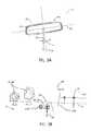
- FIG. 1is a projected view demonstrating an interior of a vehicle comprising a display system
- FIG. 2is a top schematic view demonstrating a field of view of an imager of a display system
- FIG. 3Ais a schematic diagram of a display device of a display system
- FIG. 3Bis a diagram of image data captured in a field of view of an imager of a display system
- FIG. 3Cis a diagram of a display device displaying image data corrected for a tilt of the display device.
- FIG. 4is a block diagram of a display system in accordance with the disclosure.
- relational termssuch as first and second, top and bottom, and the like, are used solely to distinguish one entity or action from another entity or action, without necessarily requiring or implying any actual such relationship or order between such entities or actions.
- the terms “comprises,” “comprising,” or any other variation thereof,are intended to cover a non-exclusive inclusion, such that a process, method, article, or apparatus that comprises a list of elements does not include only those elements but may include other elements not expressly listed or inherent to such process, method, article, or apparatus.
- a vehicle 10is shown equipped with a display system 12 .
- the display system 12comprises an imager 14 configured to capture a field of view 16 comprising a rearward directed scene 18 .
- the imager 14is configured to capture image data 44 corresponding to the field of view 16 and display the image data 44 on a display device 22 .
- the display system 12is operable to detect a tilt 24 or angular offset 6 of the device 22 in relation to gravity.
- the display device 22may comprise an inertial sensor 40 configured to detect a gravitational force vector 26 relative to a vertical display axis 28 of the display device 22 .
- the display system 12may be configured to measure an angular offset 6 of the display device 22 . Based on the angular offset 6 , a controller of the display system 12 may orient the image data 44 to display an adjusted view 30 (demonstrated in FIG. 3C ) corrected for the angular offset 6 .
- the image data 44 displayed in FIG. 1is not corrected to demonstrate an example of the appearance of the image data 44 on the display device 22 without the correction.
- the system 12may correct the image data 44 to be displayed level with gravity to correct for the tilt 24 .
- the inertial sensor 40may correspond to or comprise an accelerometer.
- the accelerometermay comprise a 3-axis accelerometer and may be configured to measure a range of approximately +/ ⁇ 4 g at a resolution of approximately 16-bits.
- the accelerometermay further be operable to operate in a wide range of temperatures and have an effective sampling rate of approximately 25 Hz.
- the inertial sensor 40may output an acceleration signal to a controller of the display system 12 . Based on the acceleration signal, the controller may identify the gravitational force vector 26 and compute the direction of gravity in relation to the vertical display axis 28 of the display device 22 .
- the controllermay utilize the gravitational force vector 26 to identify the direction of gravity in relation to the vertical display axis 28 or any other reference direction of the display device 22 .
- specific performance characteristics corresponding to the accelerometerare discussed herein, a variety of accelerometers may be utilized according to the particular precision, operating parameters of the controller, and the operating conditions/environments of the vehicle 10 .
- the display device 22may correspond to a rearview display device configured to provide a rearward directed view relative to the vehicle 10 .
- the display system 12is operable to display a series of images captured corresponding to scenes behind the vehicle 10 .
- the imager 14is in communication with the controller and comprises a pixel array configured to capture the image data 44 in the form of pixel information.
- the display system 12is configured to process the image data 44 captured by the imager 14 and apply at least one image analysis technique to identify and display the corrected view.
- a top view of the vehicle 10is shown illustrating the field of view 16 .
- the field of view 16may be directed in a rearward direction 32 relative to a forward operating direction 34 of the vehicle 10 .
- the series of images captured by the imager 14may be displayed to provide a digital representation of the field of view 16 .
- the digital representation of the field of view 16may be adjusted to simulate the operation of a conventional rearview mirror. For example, when tilted or angled relative to the rearward direction 32 , a conventional mirror may maintain the level appearance of the horizon and various features reflected from the rearward direction 32 .
- the display system 12may process and manipulate the image data 44 to maintain a relationship to gravity such that the image data 44 appears level with a horizon.
- the controller of the system 12may be in communication with the inertial sensor 40 .
- the inertial sensor 40may be disposed in or otherwise incorporated as a component of the display device 22 .
- the inertial sensor 40may be configured to detect the gravitational force vector 26 relative to the vertical display axis 28 of the display device 22 .
- the inertial sensor 40may also measure the gravitational force vector 26 relative to a horizontal display axis 42 of any other reference direction.
- the display system 12may be configured to measure an angular offset 6 of the display device 22 with respect to gravity.
- the controller of the display system 12may orient the image data 44 from the field of view 16 to display the adjusted view 30 as shown in FIG. 3C , which is further discussed in the following description.
- the controllermay adjust the image data 44 from the field of view 16 based on a horizon line 46 or a reference direction 50 detected in the image data 44 received from the imager 14 .
- the horizon line 46 and/or the reference direction 50may be identified by the processor in response to one or more image processing techniques applied to the image data 44 . In this way, the controller may be configured to determine the bearing or orientation of the reference direction 50 .
- the controller of the system 12may also generate the adjusted view 30 independently based on either the gravitational force vector 26 or the horizon line 46 .
- the controllermay align the image data 44 by orienting the image data 44 to align vertically with gravitational force vector 26 .
- the controllermay align the image data 44 by orienting the image data 44 to align horizontally with the horizon line 46 .
- the reference direction 50may be assumed or configured during an initialization of the controller.
- the reference direction 50may be assumed to be parallel to a vertical axis of the image data 44 , which may be perpendicular to a horizontal axis of the image data 44 to approximate the horizon line 46 .
- the controllermay detect changes in the gravitational force vector 26 and update the image data 44 to maintain a relationship to gravity such that the image data 44 generally appears level with the horizon.
- the controllermay be configured to identify the horizon line 46 , in the image data 44 , to identify an angular orientation of the horizon line 46 .
- the angular orientation of the horizon line 46may be applied by the controller to determine a reference direction 50 for the gravitational force vector 26 detected by the inertial sensor 40 . Accordingly, the controller may identify the reference direction 50 from the image data 44 and adjust or rotate the image data 44 to the adjusted view 30 such that the gravitational force vector 26 is aligned with the reference direction 50 , as illustrated in FIG. 3C .
- the controllermay be configured to orient and display the image data 44 on a display screen 52 of the display device 22 such that the horizon line 46 is arranged perpendicular to the gravitational force vector 26 .
- the controller of the system 12may be operable to display the image data 44 level with the horizon line 46 regardless of the angular rotation or angular offset 6 of the display device 22 with respect to gravity.
- the controllermay also utilize a relative angle or slope of the horizon line 46 , identified in the image data 44 , to identify a rotational shift of the horizon line 46 .
- the controllermay be configured to utilize various algorithms and methods.
- the controllermay be configured to utilize an adaptive edge detection process to identify the lanes and portions of a road 54 in order to identify a vanishing point 56 of the road 54 , which may intersect with the horizon line 46 .
- controllermay be configured to utilize a boundary contrast algorithm to detect the horizon line 46 by detecting a gradient threshold of a series of pixel values of the image data 44 .
- the adaptive edge detection processmay utilize an edge detection mask to approximate a gradient at pixel locations in the image data 44 . If a pixel meets predetermined criteria for an intensity value and a gradient threshold value, the controller may identify the pixels as a candidate lane line pixel. As the image data 44 corresponding to a current frame captured by the imager 14 is processed, the candidate lane line pixels may be utilized to generate a best-fit polynomial to model a lane line of the road 54 . In some embodiments, the best-fit polynomial may correspond to a third order polynomial. In this way, the candidate lane line pixels may be utilized to generate a left lane line model 54 A and a right lane line model 54 B which may correspond to sides of the road 54 . The left lane line model 54 A and the right lane line model 54 B model may be used to determine the intersection point of the sides of the road 54 , which may correspond to the vanishing point 56 in the image data 44 .
- the controllermay utilize the horizon boundary contrast algorithm to detect groups of pixels in the image data 44 in order to identify the horizon line 46 .
- Each of the groups of pixelsmay correspond to portions or patches of contiguous pixels in the image data 44 that contain the boundary between a sky portion 62 and a ground portion 64 of image data 44 .
- the horizon boundary contrast algorithmmay analyze the contrast between the sky portion 62 and the ground portion 64 to determine a location of the horizon line 46 .
- the contrastmay be analyzed by calculating a pixel intensity vertically in the image data to determine a vertical gradient.
- the vertical gradientcaptures the difference in intensity or pixel values of the pixels corresponding to the sky portion 62 and those corresponding to the ground portion 64 .
- the controllermay identify various features of the image data 44 to stabilize and/or limit variations in orientation of the image data 44 and the field of view 16 .
- the controllermay be configured to detect one or more features 66 or objects in the image data 44 .
- the features 66may correspond to the horizon line 46 , the vanishing point 56 , a tree 68 , a street sign, a vehicle 70 , and any form of object that may be detected by the controller in a plurality of image frames of the image data 44 .
- the controllermay be configured to detect a variety of objects in the image data 44 to adjust for variations in the horizon line 46 to update the orientation of the image data 44 on the display screen 52 .
- changes in the orientation of the horizon line 46may result due to fluctuations in a surface of the road 54 (e.g., undulations, potholes, speed bumps, etc.).
- the controllermay be configured to identify and/or track at least one feature 66 in the image data 44 from a first frame to a later frame. Based on the at least one feature 66 , the controller may adjust the position and/or orientation of the adjusted view 30 to stabilize the appearance of the adjusted view 30 in the image data 44 .
- the controllermay be operable to detect one or more objects (e.g., the tree 68 , the vehicle 70 , etc.) to determine and adjust the angular offset 6 to account for the movement of the at least one object or feature 66 .
- the one or more objectsmay be utilized selectively by the controller to offset the adjusted view 30 in response to one or more of the vanishing points 56 and the horizon line 46 being undetectable in the image data 44 .
- the display device 22is shown demonstrating the image data 44 adjusted by the angular offset 6 to display the adjusted view 30 .
- the controllermay process the image data 44 captured by the imager 14 to generate the adjusted view 30 .
- the controllermay process the image data 44 to identify the reference direction 50 based on the objects and/or the horizon line 46 .
- the controllermay align the reference direction 50 of the image data 44 with the gravitational force vector 26 from the inertial sensor 40 .
- the controller of the display system 12may be configured to adjust the image data 44 to mirror the appearance of the field of view 16 when the display device 22 is tilted or angled relative to the horizon line 46 or a plane of operation of the vehicle 10 .
- the adjusted view 30 of the image data 44is generated by the controller in response to changes in the orientation of the vehicle 10 relative to the horizon line 46 and changes in the orientation of the display device 22 relative to gravity.
- the controllermay be configured to correct for multiple rotational offsets of the image data 44 by aligning the gravitational force vector 26 with the reference direction 50 .
- the controller of the display device 22is operable to correct for an angular orientation of the display device 22 relative to the vehicle 10 and also correct for a change in the angular orientation of the vehicle 10 relative to the horizon line 46 .
- the display system 12may be operable to orient the image data 44 to display the adjusted view 30 such that the image data 44 is to be displayed level with gravity to correct for the tilt 24 and variations in the operating surface of the vehicle 10 .
- a pixel array of the imager 14may correspond to a complementary metal-oxide-semiconductor (CMOS) image sensor, for example, a CMOS active-pixel sensor (APS) or a charge coupled device (CCD).
- CMOScomplementary metal-oxide-semiconductor
- APSCMOS active-pixel sensor
- CCDcharge coupled device
- Each of the pixels of the pixel arraymay correspond to a photo-sensor, an array of photo-sensors, or any grouping of sensors configured to capture light.
- the controller 82may comprise a processor 84 operable to process the image data 44 as supplied in analog or digital form in the imager 14 .
- the controller 82may be implemented as a plurality of processors, a multicore processor, or any combination of processors, circuits, and peripheral processing devices.
- the controller 82may further comprise a memory 86 .
- the memory 86may comprise various forms of memory, for example, random access memory (RAM), dynamic RAM (DRAM), synchronous DRAM (SDRAM), and other forms of memory configured to store digital information.
- the memory 86may be configured to store the image data 44 for processing. Processing the image data 44 may comprise scaling and cropping the image data 44 to adjust a position and apparent size of the image data 44 as it is output to a screen of the display device 22 .
- the display device 22comprises a screen operable to display the adjusted view 30 .
- the screenmay correspond to any form of display, for example, a light-emitting diode (LED) display, liquid crystal display (LCD), organic LED (OLED) display, etc.
- the memory 86may further be configured to store a plurality of user profiles corresponding to a plurality of desired views.
- the controller 82may be in communication with a plurality of inputs.
- the controller 82may be in communication with a vehicle control module 88 via a vehicle bus 90 .
- the vehicle control module 88may be in communication with a variety of vehicle control, operation, and entertainment systems.
- the controller 82may be operable to identify a vehicle operating condition, speed, direction, a light or turn indicator status, etc. based on communications received via the vehicle bus 90 .
- the vehicle bus 90may be implemented using any suitable standard communication bus, such as a Controller Area Network (CAN) bus.
- the vehicle bus 90may also be configured to provide a variety of additional information to the controller 82 .
- CANController Area Network
- the inertial sensor 40may correspond to or comprise an accelerometer.
- the accelerometermay comprise a 3-axis accelerometer and may be configured to measure a range of approximately +/ ⁇ 4 g at a resolution of approximately 16-bits.
- the accelerometermay further be operable to operate in a wide range of temperatures and have an effective sampling rate of approximately 25 Hz.
- the inertial sensor 40may output an acceleration signal to a controller of the display system 12 .
- the controller 82may identify the gravitational force vector 26 and compute the direction of gravity in relation to the vertical display axis 28 of the display device 22 .
- the controller 82may utilize the gravitational force vector 26 to identify the direction of gravity in relation to the vertical display axis 28 or any other reference direction of the display device 22 .
- specific performance characteristics corresponding to the accelerometerare discussed herein, a variety of accelerometers may be utilized according to the particular precision, operating parameters of the controller 82 , and the operating conditions/environments of the vehicle 10 .
- the system 12may further be in communication with an additional inertial sensor configured to communicate inertial data or yaw sensor data to the controller 82 .
- the additional inertial sensormay correspond to a gyroscope or yaw sensor in communication with the vehicle control module 88 .
- the controller 82may be configured to receive steering angle data from a steering angle sensor of the vehicle 10 .
- the additional inertial data and/or the steering anglemay be communicated from the vehicle control module 88 via the vehicle bus 90 .
- the controller 82may process the additional inertial data or steering data communicated via the vehicle bus 90 to identify temporal periods or occasions when the gravitational force vector 26 may deviate from the true direction of gravity. For example, the controller 82 may process the additional inertial data and/or the steering data to identify periods when the vehicle 10 is undertaking a sharp turn, resulting in the gravitational force vector 26 detected by the inertial sensor 40 deviating from the true direction of gravity due to centrifugal forces. Accordingly, the controller 82 may correct for or filter the correction of the image data 44 to accurately process and display the adjusted view 30 based on the additional inertial data and/or the steering data. In this way, the controller 82 may improve the accuracy of the processing and generation of the adjusted view 30 .
- embodiments of the disclosure described hereinmay be comprised of one or more conventional processors and unique stored program instructions that control one or more processors to implement, in conjunction with certain non-processor circuits, some, most, or all of the functions of an image sensor system and method thereof, as described herein.
- the non-processor circuitsmay include, but, are not limited to, signal drivers, clock circuits, power source circuits, and/or user input devices.
- some or all functionscould be implemented by a state machine that has no stored program instructions, or in one or more application specific integrated circuits (ASICs), in which each function or some combinations of the functions are implemented as custom logic.
- ASICsapplication specific integrated circuits
Landscapes
- Engineering & Computer Science (AREA)
- Multimedia (AREA)
- Mechanical Engineering (AREA)
- Physics & Mathematics (AREA)
- General Physics & Mathematics (AREA)
- Theoretical Computer Science (AREA)
- Computer Vision & Pattern Recognition (AREA)
- Computer Hardware Design (AREA)
- Closed-Circuit Television Systems (AREA)
- Controls And Circuits For Display Device (AREA)
- Studio Devices (AREA)
Abstract
Description
- This application claims priority to and the benefit under 35 U.S.C. § 119(e) of U.S. Provisional Patent Application No. 62/516,827 filed on Jun. 8, 2017, entitled “DISPLAY DEVICE WITH LEVEL CORRECTION,” the entire disclosure of which is hereby incorporated herein by reference.
- The present disclosure generally relates to a display system for a vehicle and, more particularly, to a display system providing a rearward view relative to the vehicle.
- According to one aspect of the present disclosure, a display system for a vehicle is disclosed. The system comprises a display device including a screen disposed in a passenger compartment of the vehicle. The display device is configured to tilt relative to the vehicle and comprises an inertial sensor configured to output an acceleration signal. A controller is in communication with the display device and an imager configured to capture image data in a field of view rearward relative to the vehicle. The controller is operable to receive the acceleration signal and identify a direction of gravity from the acceleration signal. The controller is further configured to identify a reference direction from the image data and generate adjusted image data corrected for an angular offset of the display device between the direction of gravity and a vertical axis of the display device. The controller controls the display device to display the adjusted image data.
- According to another aspect of the present disclosure, a method for displaying image data on a vehicle display is disclosed. The method comprises detecting an angular orientation of the vehicle display relative to a vehicle and capturing image data in a field of view proximate to the vehicle. The method further comprises detecting at least one feature in the image data and identifying a reference direction based on the at least one feature. The reference direction is compared to the angular orientation of the vehicle display to generate a display offset. The display orientation of the image data is then offset by the display offset generating offset image data. The offset image data is displayed on the vehicle display.
- According to yet another aspect of the present disclosure, a display system for a vehicle is disclosed. The system comprises a display device comprising a screen disposed in a passenger compartment of the vehicle. The display device is configured to rotate relative to the vehicle and comprises an inertial sensor configured to output an acceleration signal. A controller is in communication with the display device and an imager configured to capture image data in a field of view rearward relative to the vehicle. The controller is configured receive the acceleration signal and identify a direction of gravity from the acceleration signal. The controller is further configured to identify a plurality of lane lines in the image data and calculate an intersection of the lane lines. Based on the intersection of the lane lines, the controller identifies a horizon direction in the image data. The controller generates adjusted image data corrected for an angular offset of the display device between the direction of gravity and a vertical axis of the display device and displays the adjusted image data on the display device.
- These and other features, advantages, and objects of the present disclosure will be further understood and appreciated by those skilled in the art by reference to the following specification, claims, and appended drawings.
- The present disclosure will become more fully understood from the detailed description and the accompanying drawings, wherein:
FIG. 1 is a projected view demonstrating an interior of a vehicle comprising a display system;FIG. 2 is a top schematic view demonstrating a field of view of an imager of a display system;FIG. 3A is a schematic diagram of a display device of a display system;FIG. 3B is a diagram of image data captured in a field of view of an imager of a display system;FIG. 3C is a diagram of a display device displaying image data corrected for a tilt of the display device; andFIG. 4 is a block diagram of a display system in accordance with the disclosure.- The present illustrated embodiments reside primarily in combinations of method steps and apparatus components related to an image sensor system and method thereof. Accordingly, the apparatus components and method steps have been represented, where appropriate, by conventional symbols in the drawings, showing only those specific details that are pertinent to understanding the embodiments of the present disclosure so as not to obscure the disclosure with details that will be readily apparent to those of ordinary skill in the art having the benefit of the description herein. Further, like numerals in the description and drawings represent like elements.
- In this document, relational terms, such as first and second, top and bottom, and the like, are used solely to distinguish one entity or action from another entity or action, without necessarily requiring or implying any actual such relationship or order between such entities or actions. The terms “comprises,” “comprising,” or any other variation thereof, are intended to cover a non-exclusive inclusion, such that a process, method, article, or apparatus that comprises a list of elements does not include only those elements but may include other elements not expressly listed or inherent to such process, method, article, or apparatus.
- Referring to
FIGS. 1 and 2 , avehicle 10 is shown equipped with adisplay system 12. Thedisplay system 12 comprises animager 14 configured to capture a field ofview 16 comprising a rearward directedscene 18. Theimager 14 is configured to captureimage data 44 corresponding to the field ofview 16 and display theimage data 44 on adisplay device 22. In an exemplary embodiment, thedisplay system 12 is operable to detect atilt 24 or angular offset6 of thedevice 22 in relation to gravity. As demonstrated inFIG. 1 , thedisplay device 22 may comprise aninertial sensor 40 configured to detect agravitational force vector 26 relative to avertical display axis 28 of thedisplay device 22. Accordingly, thedisplay system 12 may be configured to measure an angular offset6 of thedisplay device 22. Based on the angular offset6, a controller of thedisplay system 12 may orient theimage data 44 to display an adjusted view30 (demonstrated inFIG. 3C ) corrected for the angular offset6. Theimage data 44 displayed inFIG. 1 is not corrected to demonstrate an example of the appearance of theimage data 44 on thedisplay device 22 without the correction. As further discussed herein, thesystem 12 may correct theimage data 44 to be displayed level with gravity to correct for thetilt 24. - The
inertial sensor 40 may correspond to or comprise an accelerometer. The accelerometer may comprise a 3-axis accelerometer and may be configured to measure a range of approximately +/−4 g at a resolution of approximately 16-bits. The accelerometer may further be operable to operate in a wide range of temperatures and have an effective sampling rate of approximately 25 Hz. Accordingly, theinertial sensor 40 may output an acceleration signal to a controller of thedisplay system 12. Based on the acceleration signal, the controller may identify thegravitational force vector 26 and compute the direction of gravity in relation to thevertical display axis 28 of thedisplay device 22. Accordingly, though described as thegravitational force vector 26 herein, the controller may utilize thegravitational force vector 26 to identify the direction of gravity in relation to thevertical display axis 28 or any other reference direction of thedisplay device 22. Though specific performance characteristics corresponding to the accelerometer are discussed herein, a variety of accelerometers may be utilized according to the particular precision, operating parameters of the controller, and the operating conditions/environments of thevehicle 10. - In an exemplary embodiment, the
display device 22 may correspond to a rearview display device configured to provide a rearward directed view relative to thevehicle 10. In this configuration, thedisplay system 12 is operable to display a series of images captured corresponding to scenes behind thevehicle 10. Theimager 14 is in communication with the controller and comprises a pixel array configured to capture theimage data 44 in the form of pixel information. In the various implementations discussed herein, thedisplay system 12 is configured to process theimage data 44 captured by theimager 14 and apply at least one image analysis technique to identify and display the corrected view. - Referring to
FIG. 2 , a top view of thevehicle 10 is shown illustrating the field ofview 16. As previously described, the field ofview 16 may be directed in arearward direction 32 relative to aforward operating direction 34 of thevehicle 10. In this configuration, the series of images captured by theimager 14 may be displayed to provide a digital representation of the field ofview 16. The digital representation of the field ofview 16 may be adjusted to simulate the operation of a conventional rearview mirror. For example, when tilted or angled relative to therearward direction 32, a conventional mirror may maintain the level appearance of the horizon and various features reflected from therearward direction 32. Accordingly, in order to improve the appearance of theimage data 44 on thedisplay device 22, thedisplay system 12 may process and manipulate theimage data 44 to maintain a relationship to gravity such that theimage data 44 appears level with a horizon. - Referring to
FIGS. 3A and 3B , diagrams of thedisplay device 22 and the field ofview 16 are shown, respectively. In operation, the controller of thesystem 12 may be in communication with theinertial sensor 40. Theinertial sensor 40 may be disposed in or otherwise incorporated as a component of thedisplay device 22. Theinertial sensor 40 may be configured to detect thegravitational force vector 26 relative to thevertical display axis 28 of thedisplay device 22. Similarly, theinertial sensor 40 may also measure thegravitational force vector 26 relative to ahorizontal display axis 42 of any other reference direction. Accordingly, thedisplay system 12 may be configured to measure an angular offset6 of thedisplay device 22 with respect to gravity. - In response to receiving the angular offset6, the controller of the
display system 12 may orient theimage data 44 from the field ofview 16 to display the adjusted view30 as shown inFIG. 3C , which is further discussed in the following description. The controller may adjust theimage data 44 from the field ofview 16 based on ahorizon line 46 or areference direction 50 detected in theimage data 44 received from theimager 14. Thehorizon line 46 and/or thereference direction 50 may be identified by the processor in response to one or more image processing techniques applied to theimage data 44. In this way, the controller may be configured to determine the bearing or orientation of thereference direction 50. Though described in various exemplary embodiments as being generated based on thehorizon line 46 orreference direction 50 and thegravitational force vector 26, the controller of thesystem 12 may also generate the adjusted view30 independently based on either thegravitational force vector 26 or thehorizon line 46. For example, the controller may align theimage data 44 by orienting theimage data 44 to align vertically withgravitational force vector 26. Additionally, the controller may align theimage data 44 by orienting theimage data 44 to align horizontally with thehorizon line 46. - In some embodiments, the
reference direction 50 may be assumed or configured during an initialization of the controller. For example, thereference direction 50 may be assumed to be parallel to a vertical axis of theimage data 44, which may be perpendicular to a horizontal axis of theimage data 44 to approximate thehorizon line 46. Accordingly, if the controller is unable or inoperable to identify thereference direction 50 in the image data, thereference direction 50 may be assumed to be the vertical axis of the image data, which may be aligned by the controller to be parallel to thegravitational force vector 26. In this way, thereference direction 50 may be aligned with thegravitational force vector 26 without requiring thereference direction 50 to be identified in the image data. Based on the assumed or preconfiguredreference direction 50, the controller of thedisplay system 12 may detect changes in thegravitational force vector 26 and update theimage data 44 to maintain a relationship to gravity such that theimage data 44 generally appears level with the horizon. - Referring now to
FIGS. 3A, 3B, and 3C , the controller may be configured to identify thehorizon line 46, in theimage data 44, to identify an angular orientation of thehorizon line 46. The angular orientation of thehorizon line 46 may be applied by the controller to determine areference direction 50 for thegravitational force vector 26 detected by theinertial sensor 40. Accordingly, the controller may identify thereference direction 50 from theimage data 44 and adjust or rotate theimage data 44 to the adjusted view30 such that thegravitational force vector 26 is aligned with thereference direction 50, as illustrated inFIG. 3C . In this way, the controller may be configured to orient and display theimage data 44 on adisplay screen 52 of thedisplay device 22 such that thehorizon line 46 is arranged perpendicular to thegravitational force vector 26. In other words, by aligning thereference direction 50 of theimage data 44 withgravitational force vector 26 measured by theinertial sensor 40, the controller of thesystem 12 may be operable to display theimage data 44 level with thehorizon line 46 regardless of the angular rotation or angular offset6 of thedisplay device 22 with respect to gravity. - Referring to
FIG. 3B , in operation, the controller may also utilize a relative angle or slope of thehorizon line 46, identified in theimage data 44, to identify a rotational shift of thehorizon line 46. In order to identify thehorizon line 46 and the corresponding angular orientation of the horizon in the field ofview 16, the controller may be configured to utilize various algorithms and methods. For example, the controller may be configured to utilize an adaptive edge detection process to identify the lanes and portions of a road54 in order to identify a vanishingpoint 56 of the road54, which may intersect with thehorizon line 46. Additionally, the controller may be configured to utilize a boundary contrast algorithm to detect thehorizon line 46 by detecting a gradient threshold of a series of pixel values of theimage data 44. Though particular image processing methods are discussed herein, the methods are introduced for explanation and not limitation. As such, the disclosure shall not be limited to such exemplary embodiment unless expressly stated otherwise. - The adaptive edge detection process may utilize an edge detection mask to approximate a gradient at pixel locations in the
image data 44. If a pixel meets predetermined criteria for an intensity value and a gradient threshold value, the controller may identify the pixels as a candidate lane line pixel. As theimage data 44 corresponding to a current frame captured by theimager 14 is processed, the candidate lane line pixels may be utilized to generate a best-fit polynomial to model a lane line of the road54. In some embodiments, the best-fit polynomial may correspond to a third order polynomial. In this way, the candidate lane line pixels may be utilized to generate a leftlane line model 54A and a right lane line model54B which may correspond to sides of the road54. The leftlane line model 54A and the right lane line model54B model may be used to determine the intersection point of the sides of the road54, which may correspond to the vanishingpoint 56 in theimage data 44. - The controller may utilize the horizon boundary contrast algorithm to detect groups of pixels in the
image data 44 in order to identify thehorizon line 46. Each of the groups of pixels may correspond to portions or patches of contiguous pixels in theimage data 44 that contain the boundary between asky portion 62 and aground portion 64 ofimage data 44. The horizon boundary contrast algorithm may analyze the contrast between thesky portion 62 and theground portion 64 to determine a location of thehorizon line 46. The contrast may be analyzed by calculating a pixel intensity vertically in the image data to determine a vertical gradient. The vertical gradient captures the difference in intensity or pixel values of the pixels corresponding to thesky portion 62 and those corresponding to theground portion 64. By identifying the boundary of thesky portion 62 and theground portion 64, the controller may be operable to identify thehorizon line 46 in theimage data 44. - In some embodiments, the controller may identify various features of the
image data 44 to stabilize and/or limit variations in orientation of theimage data 44 and the field ofview 16. For example, the controller may be configured to detect one ormore features 66 or objects in theimage data 44. Thefeatures 66 may correspond to thehorizon line 46, the vanishingpoint 56, a tree68, a street sign, a vehicle70, and any form of object that may be detected by the controller in a plurality of image frames of theimage data 44. In this way, the controller may be configured to detect a variety of objects in theimage data 44 to adjust for variations in thehorizon line 46 to update the orientation of theimage data 44 on thedisplay screen 52. - In some embodiments, changes in the orientation of the
horizon line 46 may result due to fluctuations in a surface of the road54 (e.g., undulations, potholes, speed bumps, etc.). Under such circumstances, the controller may be configured to identify and/or track at least onefeature 66 in theimage data 44 from a first frame to a later frame. Based on the at least onefeature 66, the controller may adjust the position and/or orientation of the adjusted view30 to stabilize the appearance of the adjusted view30 in theimage data 44. In an exemplary embodiment, the controller may be operable to detect one or more objects (e.g., the tree68, the vehicle70, etc.) to determine and adjust the angular offset6 to account for the movement of the at least one object orfeature 66. In such embodiments, the one or more objects may be utilized selectively by the controller to offset the adjusted view30 in response to one or more of the vanishingpoints 56 and thehorizon line 46 being undetectable in theimage data 44. - Systems demonstrating various detection techniques that may be implemented in the
display system 12 are further discussed in detail in U.S. Pat. No. 9,767,695 entitled “STAND ALONE BLIND SPOT DETECTION SYSTEM,” filed on Jul. 11, 2013, by Steven G Hoek et al.; U.S. Pat. No. 8,924,078, entitled “IMAGE ACQUISITION AND PROCESSING SYSTEM FOR VEHICLE EQUIPMENT CONTROL,” filed on Oct. 17, 2011, by Oliver M. Jeromin et al.; U.S. Pat. No. 8,577,169, entitled “DIGITAL IMAGE PROCESSING AND SYSTEMS INCORPORATING THE SAME,” filed on Feb. 1, 2010, by Jeremy C. Andrus et al.; U.S. Pat. No. 8,065,053 B2, entitled “IMAGE ACQUISITION AND PROCESSING SYSTEMS FOR VEHICLE EQUIPMENT CONTROL,” filed on Jan. 31, 2011, by Joseph S. Stam et al.; and U.S. Pat. No. 8,543,254 B1, entitled “VEHICULAR IMAGING SYSTEM AND METHOD FOR DETERMINING ROADWAY WIDTH,” filed Mar. 28, 2012, by Jeremy A. Schut et al., which are incorporated by reference herein in their entirety. - Referring now to
FIG. 3C , thedisplay device 22 is shown demonstrating theimage data 44 adjusted by the angular offset6 to display the adjusted view30. As previously discussed, the controller may process theimage data 44 captured by theimager 14 to generate the adjusted view30. Particularly, the controller may process theimage data 44 to identify thereference direction 50 based on the objects and/or thehorizon line 46. With thereference direction 50, the controller may align thereference direction 50 of theimage data 44 with thegravitational force vector 26 from theinertial sensor 40. In this way, the controller of thedisplay system 12 may be configured to adjust theimage data 44 to mirror the appearance of the field ofview 16 when thedisplay device 22 is tilted or angled relative to thehorizon line 46 or a plane of operation of thevehicle 10. - In an exemplary embodiment, the adjusted view30 of the
image data 44 is generated by the controller in response to changes in the orientation of thevehicle 10 relative to thehorizon line 46 and changes in the orientation of thedisplay device 22 relative to gravity. In such embodiments, the controller may be configured to correct for multiple rotational offsets of theimage data 44 by aligning thegravitational force vector 26 with thereference direction 50. In this way, the controller of thedisplay device 22 is operable to correct for an angular orientation of thedisplay device 22 relative to thevehicle 10 and also correct for a change in the angular orientation of thevehicle 10 relative to thehorizon line 46. Accordingly, thedisplay system 12 may be operable to orient theimage data 44 to display the adjusted view30 such that theimage data 44 is to be displayed level with gravity to correct for thetilt 24 and variations in the operating surface of thevehicle 10. - Referring now to
FIG. 4 , a block diagram of thedisplay system 12 is shown. Theimager 14 is shown in communication with thecontroller 82. A pixel array of theimager 14 may correspond to a complementary metal-oxide-semiconductor (CMOS) image sensor, for example, a CMOS active-pixel sensor (APS) or a charge coupled device (CCD). Each of the pixels of the pixel array may correspond to a photo-sensor, an array of photo-sensors, or any grouping of sensors configured to capture light. Thecontroller 82 may comprise aprocessor 84 operable to process theimage data 44 as supplied in analog or digital form in theimager 14. For example, thecontroller 82 may be implemented as a plurality of processors, a multicore processor, or any combination of processors, circuits, and peripheral processing devices. - The
controller 82 may further comprise amemory 86. Thememory 86 may comprise various forms of memory, for example, random access memory (RAM), dynamic RAM (DRAM), synchronous DRAM (SDRAM), and other forms of memory configured to store digital information. Thememory 86 may be configured to store theimage data 44 for processing. Processing theimage data 44 may comprise scaling and cropping theimage data 44 to adjust a position and apparent size of theimage data 44 as it is output to a screen of thedisplay device 22. Thedisplay device 22 comprises a screen operable to display the adjusted view30. The screen may correspond to any form of display, for example, a light-emitting diode (LED) display, liquid crystal display (LCD), organic LED (OLED) display, etc. In some embodiments, thememory 86 may further be configured to store a plurality of user profiles corresponding to a plurality of desired views. - The
controller 82 may be in communication with a plurality of inputs. For example, thecontroller 82 may be in communication with avehicle control module 88 via avehicle bus 90. Thevehicle control module 88 may be in communication with a variety of vehicle control, operation, and entertainment systems. For example, thecontroller 82 may be operable to identify a vehicle operating condition, speed, direction, a light or turn indicator status, etc. based on communications received via thevehicle bus 90. Thevehicle bus 90 may be implemented using any suitable standard communication bus, such as a Controller Area Network (CAN) bus. Thevehicle bus 90 may also be configured to provide a variety of additional information to thecontroller 82. - As previously discussed, the
inertial sensor 40 may correspond to or comprise an accelerometer. The accelerometer may comprise a 3-axis accelerometer and may be configured to measure a range of approximately +/−4 g at a resolution of approximately 16-bits. The accelerometer may further be operable to operate in a wide range of temperatures and have an effective sampling rate of approximately 25 Hz. Accordingly, theinertial sensor 40 may output an acceleration signal to a controller of thedisplay system 12. Based on the acceleration signal, thecontroller 82 may identify thegravitational force vector 26 and compute the direction of gravity in relation to thevertical display axis 28 of thedisplay device 22. Accordingly, though described as thegravitational force vector 26 herein, thecontroller 82 may utilize thegravitational force vector 26 to identify the direction of gravity in relation to thevertical display axis 28 or any other reference direction of thedisplay device 22. Though specific performance characteristics corresponding to the accelerometer are discussed herein, a variety of accelerometers may be utilized according to the particular precision, operating parameters of thecontroller 82, and the operating conditions/environments of thevehicle 10. - In some embodiments, the
system 12 may further be in communication with an additional inertial sensor configured to communicate inertial data or yaw sensor data to thecontroller 82. For example, the additional inertial sensor may correspond to a gyroscope or yaw sensor in communication with thevehicle control module 88. Additionally, thecontroller 82 may be configured to receive steering angle data from a steering angle sensor of thevehicle 10. The additional inertial data and/or the steering angle may be communicated from thevehicle control module 88 via thevehicle bus 90. - In operation, the
controller 82 may process the additional inertial data or steering data communicated via thevehicle bus 90 to identify temporal periods or occasions when thegravitational force vector 26 may deviate from the true direction of gravity. For example, thecontroller 82 may process the additional inertial data and/or the steering data to identify periods when thevehicle 10 is undertaking a sharp turn, resulting in thegravitational force vector 26 detected by theinertial sensor 40 deviating from the true direction of gravity due to centrifugal forces. Accordingly, thecontroller 82 may correct for or filter the correction of theimage data 44 to accurately process and display the adjusted view30 based on the additional inertial data and/or the steering data. In this way, thecontroller 82 may improve the accuracy of the processing and generation of the adjusted view30. - It will be appreciated that embodiments of the disclosure described herein may be comprised of one or more conventional processors and unique stored program instructions that control one or more processors to implement, in conjunction with certain non-processor circuits, some, most, or all of the functions of an image sensor system and method thereof, as described herein. The non-processor circuits may include, but, are not limited to, signal drivers, clock circuits, power source circuits, and/or user input devices. Alternatively, some or all functions could be implemented by a state machine that has no stored program instructions, or in one or more application specific integrated circuits (ASICs), in which each function or some combinations of the functions are implemented as custom logic. Of course, a combination of the two approaches could be used. Thus, the methods and means for these functions have been described herein. Further, it is expected that one of ordinary skill, notwithstanding possibly significant effort and many design choices motivated by, for example, available time, current technology, and economic considerations, when guided by the concepts and principles disclosed herein will be readily capable of generating such software instructions and programs and ICs with minimal experimentation.
- It should be appreciated by those skilled in the art that the above-described components may be combined in additional or alternative ways not explicitly described herein. Modifications of the various implementations of the disclosure will occur to those skilled in the art and to those who apply the teachings of the disclosure. Therefore, it is understood that the embodiments shown in the drawings and described above are merely for illustrative purposes and not intended to limit the scope of the disclosure, which is defined by the following claims as interpreted according to the principles of patent law, including the Doctrine of Equivalents.
Claims (20)
Priority Applications (1)
| Application Number | Priority Date | Filing Date | Title |
|---|---|---|---|
| US16/001,017US10668883B2 (en) | 2017-06-08 | 2018-06-06 | Display device with level correction |
Applications Claiming Priority (2)
| Application Number | Priority Date | Filing Date | Title |
|---|---|---|---|
| US201762516827P | 2017-06-08 | 2017-06-08 | |
| US16/001,017US10668883B2 (en) | 2017-06-08 | 2018-06-06 | Display device with level correction |
Publications (2)
| Publication Number | Publication Date |
|---|---|
| US20180354442A1true US20180354442A1 (en) | 2018-12-13 |
| US10668883B2 US10668883B2 (en) | 2020-06-02 |
Family
ID=64562834
Family Applications (1)
| Application Number | Title | Priority Date | Filing Date |
|---|---|---|---|
| US16/001,017ActiveUS10668883B2 (en) | 2017-06-08 | 2018-06-06 | Display device with level correction |
Country Status (4)
| Country | Link |
|---|---|
| US (1) | US10668883B2 (en) |
| EP (1) | EP3634809B1 (en) |
| CN (1) | CN110621543B (en) |
| WO (1) | WO2018226825A1 (en) |
Cited By (5)
| Publication number | Priority date | Publication date | Assignee | Title |
|---|---|---|---|---|
| EP3671722A2 (en)* | 2018-12-20 | 2020-06-24 | Seiko Epson Corporation | Circuit device, electronic device, and vehicle |
| US11004245B2 (en)* | 2017-07-25 | 2021-05-11 | Lg Electronics Inc. | User interface apparatus for vehicle and vehicle |
| US20220242304A1 (en)* | 2019-06-03 | 2022-08-04 | Third Eye Design, Inc. | Remote lighting system and methods of operating same |
| US20230410248A1 (en)* | 2020-11-11 | 2023-12-21 | Robert Bosch Gmbh | Image data generator, lean vehicle, and image data generation method |
| US20240299123A1 (en)* | 2023-03-10 | 2024-09-12 | Arthrex, Inc | Camera apparatus for coordinated operation with surgical tools |
Families Citing this family (1)
| Publication number | Priority date | Publication date | Assignee | Title |
|---|---|---|---|---|
| US20180162291A1 (en)* | 2016-12-12 | 2018-06-14 | Wipro Limited | System and method of dynamically adjusting field of view of an image capturing device |
Citations (25)
| Publication number | Priority date | Publication date | Assignee | Title |
|---|---|---|---|---|
| US4837551A (en)* | 1988-02-03 | 1989-06-06 | Yazaki Corporation | Display apparatus for automotive vehicle |
| US5028912A (en)* | 1988-02-03 | 1991-07-02 | Yazaki Corporation | Display apparatus for automotive vehicle |
| US5734357A (en)* | 1994-12-02 | 1998-03-31 | Fujitsu Limited | Vehicular display device adjusting to driver's positions |
| US20060164230A1 (en)* | 2000-03-02 | 2006-07-27 | Dewind Darryl P | Interior mirror assembly with display |
| US20070262574A1 (en)* | 1982-06-18 | 2007-11-15 | Intelligent Technologies International, Inc. | Optical Monitoring of Vehicle Interiors |
| US20080204566A1 (en)* | 2005-09-09 | 2008-08-28 | Canon Kabushiki Kaisha | Image pickup apparatus |
| US20100201814A1 (en)* | 2009-02-06 | 2010-08-12 | Gm Global Technology Operations, Inc. | Camera auto-calibration by horizon estimation |
| US7815313B2 (en)* | 2004-08-02 | 2010-10-19 | Nissan Motor Co., Ltd. | Drive sense adjusting apparatus and drive sense adjusting method |
| US7860626B2 (en)* | 1995-06-07 | 2010-12-28 | Automotive Technologies International, Inc. | Vehicular heads-up display system with adjustable viewing |
| US20130038732A1 (en)* | 2011-08-09 | 2013-02-14 | Continental Automotive Systems, Inc. | Field of view matching video display system |
| US20130050530A1 (en)* | 2011-08-30 | 2013-02-28 | Hon Hai Precision Industry Co., Ltd. | Image capturing device and image processing method thereof |
| US20130321629A1 (en)* | 2012-05-31 | 2013-12-05 | GM Global Technology Operations LLC | Dynamic guideline overlay with image cropping |
| US20140043473A1 (en)* | 2011-04-25 | 2014-02-13 | Nikhil Gupta | Method and system for dynamically calibrating vehicular cameras |
| US8654236B2 (en)* | 2010-06-17 | 2014-02-18 | Canon Kabushiki Kaisha | Imaging apparatus including a control unit configured to change a correction value for correcting an output of an orientation detection unit |
| US20140184799A1 (en)* | 2011-08-01 | 2014-07-03 | Magna Electronic Inc. | Vehicle camera alignment system |
| US20150049193A1 (en)* | 2011-04-25 | 2015-02-19 | Magna International Inc. | Method and system for dynamically calibrating vehicular cameras |
| US20150237311A1 (en)* | 2014-02-17 | 2015-08-20 | Denson Corporation | Apparatus and program for generating image to be displayed |
| US20160027298A1 (en)* | 2014-07-24 | 2016-01-28 | Gentex Corporation | Accelerometer integrated with display device |
| US20160137126A1 (en)* | 2013-06-21 | 2016-05-19 | Magna Electronics Inc. | Vehicle vision system |
| US20160277651A1 (en)* | 2015-03-19 | 2016-09-22 | Gentex Corporation | Image processing for camera based display system |
| US20170120829A1 (en)* | 2015-02-02 | 2017-05-04 | Panasonic Intellectual Property Management Co., Ltd. | Electronic mirror device and electronic mirror system using same |
| US20170327044A1 (en)* | 2016-05-11 | 2017-11-16 | Magna Mirrors Of America, Inc. | Vehicle vision system with display by a mirror |
| US20180184006A1 (en)* | 2016-12-27 | 2018-06-28 | Canon Kabushiki Kaisha | Imaging control apparatus and method for controlling the same |
| US20180297523A1 (en)* | 2017-04-14 | 2018-10-18 | Panasonic Automotive Systems Company Of America, Division Of Panasonic Corporation Of North America | Rear view display adjustable virtual camera view point system and method |
| US20190111845A1 (en)* | 2017-10-12 | 2019-04-18 | Magna Electronics Inc. | Vehicle vision system with bird's eye view display |
Family Cites Families (14)
| Publication number | Priority date | Publication date | Assignee | Title |
|---|---|---|---|---|
| FR2848161B1 (en)* | 2002-12-09 | 2005-12-09 | Valeo Vision | VEHICLE PROJECTOR ORIENTATION CONTROL SYSTEM AND METHOD OF IMPLEMENTING THE SAME |
| JP4838261B2 (en) | 2004-11-18 | 2011-12-14 | ジェンテックス コーポレイション | Image collection and processing system for vehicle equipment control |
| US8924078B2 (en) | 2004-11-18 | 2014-12-30 | Gentex Corporation | Image acquisition and processing system for vehicle equipment control |
| US9009984B2 (en) | 2008-09-08 | 2015-04-21 | Qualcomm Incorporated | Multi-panel electronic device |
| WO2010088465A1 (en) | 2009-02-02 | 2010-08-05 | Gentex Corporation | Improved digital image processing and systems incorporating the same |
| US8543254B1 (en) | 2012-03-28 | 2013-09-24 | Gentex Corporation | Vehicular imaging system and method for determining roadway width |
| US10410605B2 (en)* | 2012-07-09 | 2019-09-10 | Blackberry Limited | System and method for determining a display orientation of a mobile device |
| US9767695B2 (en) | 2012-07-11 | 2017-09-19 | Gentex Corporation | Stand alone blind spot detection system |
| US9445011B2 (en)* | 2012-10-22 | 2016-09-13 | GM Global Technology Operations LLC | Dynamic rearview mirror adaptive dimming overlay through scene brightness estimation |
| CN105517844B (en)* | 2013-09-04 | 2018-10-19 | 金泰克斯公司 | The rearview assembly for showing image of vehicle |
| KR101609303B1 (en)* | 2014-03-28 | 2016-04-20 | 주식회사 하나비전테크 | Method to calibrate camera and apparatus therefor |
| JP6518069B2 (en)* | 2015-01-09 | 2019-05-22 | キヤノン株式会社 | Display device, imaging system, display device control method, program, and recording medium |
| US10946799B2 (en)* | 2015-04-21 | 2021-03-16 | Magna Electronics Inc. | Vehicle vision system with overlay calibration |
| CN106627366A (en) | 2016-09-12 | 2017-05-10 | 北京新能源汽车股份有限公司 | Automobile rear view display system and method and automobile |
- 2018
- 2018-06-06USUS16/001,017patent/US10668883B2/enactiveActive
- 2018-06-06WOPCT/US2018/036252patent/WO2018226825A1/ennot_activeCeased
- 2018-06-06EPEP18814205.3Apatent/EP3634809B1/enactiveActive
- 2018-06-06CNCN201880031418.5Apatent/CN110621543B/enactiveActive
Patent Citations (34)
| Publication number | Priority date | Publication date | Assignee | Title |
|---|---|---|---|---|
| US20070262574A1 (en)* | 1982-06-18 | 2007-11-15 | Intelligent Technologies International, Inc. | Optical Monitoring of Vehicle Interiors |
| US5028912A (en)* | 1988-02-03 | 1991-07-02 | Yazaki Corporation | Display apparatus for automotive vehicle |
| US4837551A (en)* | 1988-02-03 | 1989-06-06 | Yazaki Corporation | Display apparatus for automotive vehicle |
| US5734357A (en)* | 1994-12-02 | 1998-03-31 | Fujitsu Limited | Vehicular display device adjusting to driver's positions |
| US7860626B2 (en)* | 1995-06-07 | 2010-12-28 | Automotive Technologies International, Inc. | Vehicular heads-up display system with adjustable viewing |
| US20060164230A1 (en)* | 2000-03-02 | 2006-07-27 | Dewind Darryl P | Interior mirror assembly with display |
| US7815313B2 (en)* | 2004-08-02 | 2010-10-19 | Nissan Motor Co., Ltd. | Drive sense adjusting apparatus and drive sense adjusting method |
| US20080204566A1 (en)* | 2005-09-09 | 2008-08-28 | Canon Kabushiki Kaisha | Image pickup apparatus |
| US20100201814A1 (en)* | 2009-02-06 | 2010-08-12 | Gm Global Technology Operations, Inc. | Camera auto-calibration by horizon estimation |
| US8259174B2 (en)* | 2009-02-06 | 2012-09-04 | GM Global Technology Operations LLC | Camera auto-calibration by horizon estimation |
| US8654236B2 (en)* | 2010-06-17 | 2014-02-18 | Canon Kabushiki Kaisha | Imaging apparatus including a control unit configured to change a correction value for correcting an output of an orientation detection unit |
| US20150049193A1 (en)* | 2011-04-25 | 2015-02-19 | Magna International Inc. | Method and system for dynamically calibrating vehicular cameras |
| US20160267657A1 (en)* | 2011-04-25 | 2016-09-15 | Magna Electronics Inc. | Method for dynamically calibrating vehicular cameras |
| US20140043473A1 (en)* | 2011-04-25 | 2014-02-13 | Nikhil Gupta | Method and system for dynamically calibrating vehicular cameras |
| US9834153B2 (en)* | 2011-04-25 | 2017-12-05 | Magna Electronics Inc. | Method and system for dynamically calibrating vehicular cameras |
| US20180086284A1 (en)* | 2011-04-25 | 2018-03-29 | Magna Electronics Inc. | Method and system for dynamically ascertaining alignment of vehicular cameras |
| US9357208B2 (en)* | 2011-04-25 | 2016-05-31 | Magna Electronics Inc. | Method and system for dynamically calibrating vehicular cameras |
| US10202077B2 (en)* | 2011-04-25 | 2019-02-12 | Magna Electronics Inc. | Method for dynamically calibrating vehicular cameras |
| US20140184799A1 (en)* | 2011-08-01 | 2014-07-03 | Magna Electronic Inc. | Vehicle camera alignment system |
| US9491450B2 (en)* | 2011-08-01 | 2016-11-08 | Magna Electronic Inc. | Vehicle camera alignment system |
| US20130038732A1 (en)* | 2011-08-09 | 2013-02-14 | Continental Automotive Systems, Inc. | Field of view matching video display system |
| US20130050530A1 (en)* | 2011-08-30 | 2013-02-28 | Hon Hai Precision Industry Co., Ltd. | Image capturing device and image processing method thereof |
| US20130321629A1 (en)* | 2012-05-31 | 2013-12-05 | GM Global Technology Operations LLC | Dynamic guideline overlay with image cropping |
| US9738223B2 (en)* | 2012-05-31 | 2017-08-22 | GM Global Technology Operations LLC | Dynamic guideline overlay with image cropping |
| US20160137126A1 (en)* | 2013-06-21 | 2016-05-19 | Magna Electronics Inc. | Vehicle vision system |
| US20150237311A1 (en)* | 2014-02-17 | 2015-08-20 | Denson Corporation | Apparatus and program for generating image to be displayed |
| US9836966B2 (en)* | 2014-07-24 | 2017-12-05 | Gentex Corporation | Accelerometer integrated with display device |
| US20160027298A1 (en)* | 2014-07-24 | 2016-01-28 | Gentex Corporation | Accelerometer integrated with display device |
| US20170120829A1 (en)* | 2015-02-02 | 2017-05-04 | Panasonic Intellectual Property Management Co., Ltd. | Electronic mirror device and electronic mirror system using same |
| US20160277651A1 (en)* | 2015-03-19 | 2016-09-22 | Gentex Corporation | Image processing for camera based display system |
| US20170327044A1 (en)* | 2016-05-11 | 2017-11-16 | Magna Mirrors Of America, Inc. | Vehicle vision system with display by a mirror |
| US20180184006A1 (en)* | 2016-12-27 | 2018-06-28 | Canon Kabushiki Kaisha | Imaging control apparatus and method for controlling the same |
| US20180297523A1 (en)* | 2017-04-14 | 2018-10-18 | Panasonic Automotive Systems Company Of America, Division Of Panasonic Corporation Of North America | Rear view display adjustable virtual camera view point system and method |
| US20190111845A1 (en)* | 2017-10-12 | 2019-04-18 | Magna Electronics Inc. | Vehicle vision system with bird's eye view display |
Cited By (7)
| Publication number | Priority date | Publication date | Assignee | Title |
|---|---|---|---|---|
| US11004245B2 (en)* | 2017-07-25 | 2021-05-11 | Lg Electronics Inc. | User interface apparatus for vehicle and vehicle |
| EP3671722A2 (en)* | 2018-12-20 | 2020-06-24 | Seiko Epson Corporation | Circuit device, electronic device, and vehicle |
| US20220242304A1 (en)* | 2019-06-03 | 2022-08-04 | Third Eye Design, Inc. | Remote lighting system and methods of operating same |
| US11938861B2 (en)* | 2019-06-03 | 2024-03-26 | Third Eye Design, Inc. | Remote lighting system and methods of operating same |
| US20230410248A1 (en)* | 2020-11-11 | 2023-12-21 | Robert Bosch Gmbh | Image data generator, lean vehicle, and image data generation method |
| US20240299123A1 (en)* | 2023-03-10 | 2024-09-12 | Arthrex, Inc | Camera apparatus for coordinated operation with surgical tools |
| US12419719B2 (en)* | 2023-03-10 | 2025-09-23 | Arthrex, Inc. | Camera apparatus for coordinated operation with surgical tools |
Also Published As
| Publication number | Publication date |
|---|---|
| CN110621543A (en) | 2019-12-27 |
| WO2018226825A1 (en) | 2018-12-13 |
| EP3634809A1 (en) | 2020-04-15 |
| CN110621543B (en) | 2022-12-16 |
| EP3634809B1 (en) | 2022-03-16 |
| US10668883B2 (en) | 2020-06-02 |
| EP3634809A4 (en) | 2020-04-15 |
Similar Documents
| Publication | Publication Date | Title |
|---|---|---|
| US10668883B2 (en) | Display device with level correction | |
| US11412123B2 (en) | Image processing for camera based vehicle display system | |
| Zhu et al. | The multivehicle stereo event camera dataset: An event camera dataset for 3D perception | |
| US10625660B2 (en) | Camera based headlight control system | |
| US11535154B2 (en) | Method for calibrating a vehicular vision system | |
| US20150042800A1 (en) | Apparatus and method for providing avm image | |
| US8526681B2 (en) | On-vehicle image processing device for vehicular control | |
| US20150181198A1 (en) | Automatic Scene Calibration | |
| JP6032034B2 (en) | Object detection device | |
| GB2591041A (en) | Augmented reality display view generation | |
| JP6614042B2 (en) | Posture change determination device, overhead view video generation device, overhead view video generation system, posture change determination method, and program | |
| CN105141912B (en) | A kind of method and apparatus of signal lamp reorientation | |
| JP2016030554A (en) | In-vehicle camera mounting attitude detection method and in-vehicle camera mounting attitude detection apparatus | |
| CA2993265C (en) | Systems and methods for northfinding | |
| KR102152720B1 (en) | Photographing apparatus and method for 3d modeling | |
| US20230271555A1 (en) | Vehicle rearview display system with orientation sensing | |
| US8937643B1 (en) | Offset rolling shutter camera model, and applications thereof | |
| JP2006163569A (en) | Object detection apparatus and object detection method | |
| CN103043000A (en) | Obstacle detection system and obstacle detection method thereof | |
| US10560631B2 (en) | Motion vector acquiring device, motion vector acquiring method, and storage medium | |
| Zheng et al. | Understanding vehicle motion via spatial integration of intensities | |
| JP2018116620A (en) | Image processing device, image processing system, and image processing method | |
| CN119380046A (en) | Relevance matching method and relevance matching system |
Legal Events
| Date | Code | Title | Description |
|---|---|---|---|
| AS | Assignment | Owner name:GENTEX CORPORATION, MICHIGAN Free format text:ASSIGNMENT OF ASSIGNORS INTEREST;ASSIGNOR:BERGSTROM, STUART A;REEL/FRAME:045997/0138 Effective date:20180605 | |
| FEPP | Fee payment procedure | Free format text:ENTITY STATUS SET TO UNDISCOUNTED (ORIGINAL EVENT CODE: BIG.); ENTITY STATUS OF PATENT OWNER: LARGE ENTITY | |
| STPP | Information on status: patent application and granting procedure in general | Free format text:DOCKETED NEW CASE - READY FOR EXAMINATION | |
| STPP | Information on status: patent application and granting procedure in general | Free format text:NON FINAL ACTION MAILED | |
| STPP | Information on status: patent application and granting procedure in general | Free format text:RESPONSE TO NON-FINAL OFFICE ACTION ENTERED AND FORWARDED TO EXAMINER | |
| STPP | Information on status: patent application and granting procedure in general | Free format text:FINAL REJECTION MAILED | |
| STCV | Information on status: appeal procedure | Free format text:NOTICE OF APPEAL FILED | |
| STPP | Information on status: patent application and granting procedure in general | Free format text:NOTICE OF ALLOWANCE MAILED -- APPLICATION RECEIVED IN OFFICE OF PUBLICATIONS | |
| STPP | Information on status: patent application and granting procedure in general | Free format text:NOTICE OF ALLOWANCE MAILED -- APPLICATION RECEIVED IN OFFICE OF PUBLICATIONS | |
| STCF | Information on status: patent grant | Free format text:PATENTED CASE | |
| MAFP | Maintenance fee payment | Free format text:PAYMENT OF MAINTENANCE FEE, 4TH YEAR, LARGE ENTITY (ORIGINAL EVENT CODE: M1551); ENTITY STATUS OF PATENT OWNER: LARGE ENTITY Year of fee payment:4 |