US20180219281A1 - Antenna device and method for manufacturing antenna device - Google Patents
Antenna device and method for manufacturing antenna deviceDownload PDFInfo
- Publication number
- US20180219281A1 US20180219281A1US15/886,117US201815886117AUS2018219281A1US 20180219281 A1US20180219281 A1US 20180219281A1US 201815886117 AUS201815886117 AUS 201815886117AUS 2018219281 A1US2018219281 A1US 2018219281A1
- Authority
- US
- United States
- Prior art keywords
- radome
- antenna module
- antenna
- feed
- elements
- Prior art date
- Legal status (The legal status is an assumption and is not a legal conclusion. Google has not performed a legal analysis and makes no representation as to the accuracy of the status listed.)
- Abandoned
Links
- 238000004519manufacturing processMethods0.000titleclaimsdescription4
- 238000000034methodMethods0.000titleclaimsdescription4
- 230000003071parasitic effectEffects0.000claimsabstractdescription78
- 239000000758substrateSubstances0.000claimsabstractdescription38
- 239000012790adhesive layerSubstances0.000claimsabstractdescription22
- 230000008878couplingEffects0.000claimsabstractdescription15
- 238000010168coupling processMethods0.000claimsabstractdescription15
- 238000005859coupling reactionMethods0.000claimsabstractdescription15
- 230000005855radiationEffects0.000claimsabstractdescription4
- 239000010410layerSubstances0.000claimsdescription15
- 230000004048modificationEffects0.000description16
- 238000012986modificationMethods0.000description16
- 239000002184metalSubstances0.000description7
- 239000004020conductorSubstances0.000description6
- 238000006073displacement reactionMethods0.000description6
- 239000011800void materialSubstances0.000description6
- 239000011347resinSubstances0.000description3
- 229920005989resinPolymers0.000description3
- 238000007789sealingMethods0.000description3
- 230000000694effectsEffects0.000description2
- 230000005540biological transmissionEffects0.000description1
- 238000004891communicationMethods0.000description1
- 230000003247decreasing effectEffects0.000description1
- 239000011159matrix materialSubstances0.000description1
Images


Classifications
- H—ELECTRICITY
- H01—ELECTRIC ELEMENTS
- H01Q—ANTENNAS, i.e. RADIO AERIALS
- H01Q1/00—Details of, or arrangements associated with, antennas
- H01Q1/42—Housings not intimately mechanically associated with radiating elements, e.g. radome
- H01Q1/422—Housings not intimately mechanically associated with radiating elements, e.g. radome comprising two or more layers of dielectric material
- H—ELECTRICITY
- H01—ELECTRIC ELEMENTS
- H01Q—ANTENNAS, i.e. RADIO AERIALS
- H01Q1/00—Details of, or arrangements associated with, antennas
- H01Q1/50—Structural association of antennas with earthing switches, lead-in devices or lightning protectors
- H—ELECTRICITY
- H01—ELECTRIC ELEMENTS
- H01Q—ANTENNAS, i.e. RADIO AERIALS
- H01Q1/00—Details of, or arrangements associated with, antennas
- H01Q1/36—Structural form of radiating elements, e.g. cone, spiral, umbrella; Particular materials used therewith
- H01Q1/38—Structural form of radiating elements, e.g. cone, spiral, umbrella; Particular materials used therewith formed by a conductive layer on an insulating support
- H—ELECTRICITY
- H01—ELECTRIC ELEMENTS
- H01Q—ANTENNAS, i.e. RADIO AERIALS
- H01Q1/00—Details of, or arrangements associated with, antennas
- H01Q1/40—Radiating elements coated with or embedded in protective material
- H01Q1/405—Radome integrated radiating elements
- H—ELECTRICITY
- H01—ELECTRIC ELEMENTS
- H01Q—ANTENNAS, i.e. RADIO AERIALS
- H01Q1/00—Details of, or arrangements associated with, antennas
- H01Q1/42—Housings not intimately mechanically associated with radiating elements, e.g. radome
- H—ELECTRICITY
- H01—ELECTRIC ELEMENTS
- H01Q—ANTENNAS, i.e. RADIO AERIALS
- H01Q1/00—Details of, or arrangements associated with, antennas
- H01Q1/52—Means for reducing coupling between antennas; Means for reducing coupling between an antenna and another structure
- H—ELECTRICITY
- H01—ELECTRIC ELEMENTS
- H01Q—ANTENNAS, i.e. RADIO AERIALS
- H01Q21/00—Antenna arrays or systems
- H01Q21/0006—Particular feeding systems
- H—ELECTRICITY
- H01—ELECTRIC ELEMENTS
- H01Q—ANTENNAS, i.e. RADIO AERIALS
- H01Q21/00—Antenna arrays or systems
- H01Q21/06—Arrays of individually energised antenna units similarly polarised and spaced apart
- H01Q21/08—Arrays of individually energised antenna units similarly polarised and spaced apart the units being spaced along or adjacent to a rectilinear path
- H—ELECTRICITY
- H01—ELECTRIC ELEMENTS
- H01Q—ANTENNAS, i.e. RADIO AERIALS
- H01Q9/00—Electrically-short antennas having dimensions not more than twice the operating wavelength and consisting of conductive active radiating elements
- H01Q9/04—Resonant antennas
- H01Q9/0407—Substantially flat resonant element parallel to ground plane, e.g. patch antenna
- H01Q9/045—Substantially flat resonant element parallel to ground plane, e.g. patch antenna with particular feeding means
- H01Q9/0457—Substantially flat resonant element parallel to ground plane, e.g. patch antenna with particular feeding means electromagnetically coupled to the feed line
Definitions
- the present disclosurerelates to an antenna device and a method for manufacturing the antenna device.
- a wireless devicewhich includes a substrate, a wireless module that is mounted on the substrate, and a housing that houses the substrate and the wireless module (Japanese Unexamined Patent Application Publication No. 2015-8410).
- a void having a length that is substantially equal to a multiple of a half wavelength of radio waves corresponding to a communication frequency of the antenna portionis ensured.
- a stack type microstrip antenna including a passive element (parasitic element) above a driven element (feed element) of the microstrip antennahas been known (see Japanese Unexamined Patent Application Publication No. 03-74908).
- the parasitic elementis attached to the inner surface of a radome that covers the entirety of the antenna or embedded within the radome.
- the driven elementis mounted on a metal base, and the radome is mounted on the metal base so as to cover the driven element.
- both the driven element and the radomeare fixed to the metal base.
- alignmenthas to be performed such that the central axis of the driven element and the central axis of a parasitic element provided on the radome coincide with each other. If displacement occurs either in the step of mounting the driven element to the metal base or in the step of mounting the radome to the metal base, displacement occurs between the driven element and the parasitic element.
- an object of the present disclosureto provide an antenna device that is suitable for thickness reduction of the device and in which displacement less likely to occur between a feed element and a parasitic element.
- An antenna deviceincludes:
- an antenna moduleincluding a dielectric substrate and a feed element provided on, in, or above the dielectric substrate;
- a radomecomprising a dielectric and disposed so as to oppose the antenna module in a radiation direction of the feed element
- an adhesive layerdisposed between the antenna module and the radome to bond the antenna module to the radome.
- the adhesive layeris interposed between the feed element of the antenna module and the parasitic element provided on the radome. It is possible to make the feed element and the parasitic element closer to each other as compared to a configuration in which a void is ensured therebetween, and thus it is possible to reduce the thickness of the antenna device.
- the antenna moduleis directly bonded to the radome by the adhesive layer, displacement between the feed element of the antenna module and the parasitic element provided on the radome is less likely to occur, as compared to a configuration in which the antenna module and the radome are mounted to a common base member.
- the adhesive layerhas a lower dielectric constant than the dielectric substrate.
- an antenna devicein addition to the configurations of the antenna devices according to the first and second aspects,
- the feed element of the antenna moduleis provided on a surface of the dielectric substrate, and the antenna module further includes a dielectric layer covering the surface of the dielectric substrate and the feed element, and
- the dielectric layeris bonded to the radome by the adhesive layer.
- the interval between the feed element and the parasitic elementis large as compared to the case where the dielectric layer is not disposed. As a result, it is possible to weaken electromagnetic coupling between the feed element and the parasitic element.
- a step surface restricting a position of the antenna module in an in-plane directionis provided on an inner surface of the radome.
- the radomein addition to the configurations of the antenna devices according to the first to fourth aspects, also serves as a housing which houses the antenna module.
- the radomealso serves as a housing, it is possible to reduce the number of components and also further reduce the thickness of the antenna device.
- an antenna devicein addition to the configurations of the antenna devices according to the first to fifth aspects,
- the antenna moduleincludes a plurality of other feed elements provided on the dielectric substrate in addition to the feed element, and the plurality of the other feed elements constitutes an array antenna, and
- a plurality of other parasitic elementsare provided in, on, or above the radome in addition to the parasitic element, and the plurality of the other parasitic elements are electromagnetically coupled with the plurality of the other feed elements, respectively.
- a method for producing an antenna device according to a seventh aspect of the present disclosureincludes the steps of:
- an antenna moduleincluding a dielectric substrate and a feed element provided on the dielectric substrate;
- the adhesive layeris interposed between the feed element of the antenna module and the parasitic element provided on the radome. It is possible to make the feed element and the parasitic element closer to each other as compared to a configuration in which a void is ensured therebetween, and thus it is possible to reduce the thickness of the antenna device.
- the antenna moduleis directly bonded to the radome by the adhesive layer, displacement between the feed element of the antenna module and the parasitic element provided on the radome is less likely to occur, as compared to a method in which the antenna module and the radome are mounted to a common base member.
- FIG. 1Ais a partial cross-sectional view of a radome and parasitic elements used in an antenna device according to a first embodiment
- FIG. 1Bis a cross-sectional view of an antenna module used in the antenna device according to the first embodiment
- FIG. 1Cis a cross-sectional view of the antenna device in a state where the radome and the antenna module are bonded to each other;
- FIG. 1Dis a plan view of the antenna device
- FIG. 2is a cross-sectional view of an antenna device according to a modification of the first embodiment
- FIG. 3Ais a cross-sectional view of an antenna module used in an antenna device according to a second embodiment
- FIG. 3Bis a cross-sectional view of the antenna device according to the second embodiment
- FIG. 4Ais a cross-sectional view of an antenna device according to a third embodiment
- FIG. 4Bis a plan view of the antenna device according to the third embodiment.
- FIG. 5Ais a plan view of an antenna device according to a first modification of the third embodiment.
- FIG. 5Bis a perspective view before an antenna device according to a second modification of the third embodiment is assembled.
- FIGS. 1A to 1DAn antenna device according to a first embodiment will be described with reference to FIGS. 1A to 1D .
- FIG. 1Ais a partial cross-sectional view of a radome 10 and parasitic elements 12 used in the antenna device according to the first embodiment.
- the radome 10is, for example, a plate-like member formed from a dielectric.
- a plurality of parasitic elements 12are provided on one surface (inner surface) of the radome 10 .
- FIG. 1Bis a cross-sectional view of an antenna module 20 used in the antenna device according to the first embodiment.
- a plurality of feed elements 22are formed on one surface (first surface) 21 A of a dielectric substrate 21 .
- patch antennasare used as the feed elements 22 .
- a high-frequency integrated circuit element 30is mounted on a second surface 21 B of the dielectric substrate 21 opposite to the first surface 21 A.
- a ground plane 23is disposed in an inner layer of the dielectric substrate 21 .
- Each of the plurality of feed elements 22is connected to a high-frequency signal terminal of the high-frequency integrated circuit element 30 via a transmission line 24 provided within the dielectric substrate 21 .
- the ground plane 23is connected to a ground terminal of the high-frequency integrated circuit element 30 via a wire 25 provided within the dielectric substrate 21 .
- a plurality of conductor columns 31project from the second surface 21 B of the dielectric substrate 21 .
- the plurality of conductor columns 31 and the high-frequency integrated circuit element 30are embedded within a sealing resin layer 40 .
- Each conductor column 31reaches the surface of the sealing resin layer 40 .
- a plurality of lands 41are provided on the surface of the sealing resin layer 40 so as to correspond to the plurality of conductor columns 31 .
- Some of the terminals of the high-frequency integrated circuit element 30are connected to the corresponding lands 41 via wires 26 within the dielectric substrate 21 and the conductor columns 31 .
- the ground plane 23is connected to the lands 41 for grounding via wires 27 within the dielectric substrate 21 and the conductor columns 31 .
- FIG. 1Cis a cross-sectional view of the antenna device in a state where the radome 10 and the antenna module 20 are bonded to each other.
- the antenna module 20 and the radome 10are bonded to each other by an adhesive layer 50 such that the surface (first surface 21 A) of the antenna module 20 on which the feed elements 22 are formed opposes the inner surface of the radome 10 on which the parasitic elements 12 are formed.
- the radome 10is disposed so as to be spaced apart from the antenna module 20 across a gap in a radiation direction of the feed elements 22 .
- Each feed element 22is disposed so as to oppose the corresponding parasitic element 12 , and each parasitic element 12 is electromagnetically coupled with the corresponding feed element 22 .
- the dielectric constant of the adhesive layer 50is lower than the dielectric constant of the dielectric substrate 21 .
- FIG. 1Dis a plan view of the antenna device.
- the radome 10is larger than the antenna module 20 , and the antenna module 20 is disposed within the radome 10 .
- the plurality of feed elements 22 and the plurality of parasitic elements 12are disposed regularly within the surfaces, for example, in a matrix manner.
- the plurality of feed elements 22 and the plurality of parasitic elements 12constitutes an array antenna.
- the radome 10has a function to protect the antenna module 20 .
- the radome 10also serves as a housing of the portable terminal that houses the antenna module 20 .
- the adhesive layer 50which is formed from a dielectric, is disposed between the feed elements 22 and the parasitic elements 12 .
- the contact therebetweendoes not occur.
- the electromagnetic coupling between one feed element 22 and the parasitic element 12 opposing to the feed element 22 adjacent to the one feed element 22easily occurs.
- the feed element 22 and the adjacent parasitic element 12are electromagnetically coupled with each other, desired antenna characteristics are not obtained.
- each of the antenna module 20 and the radome 10is fixed to another common base member
- an error in positioning of the antenna module 20 and the base member and an error in positioning of the radome 10 and the base memberare superimposed on an error in positioning of the antenna module 20 and the radome 10 .
- the antenna module 20is directly positioned and fixed to the radome 10 via the adhesive layer 50 , it is possible to reduce an error in positioning.
- FIG. 2is a cross-sectional view of an antenna device according to the modification of the first embodiment.
- the parasitic elements 12are provided on the inner surface of the radome 10 .
- the parasitic elements 12are embedded within the radome 10 .
- the present modificationit is possible to increase the interval between the feed elements 22 and the parasitic elements 12 as compared to the structure of the first embodiment. As a result, it is possible to weaken the electromagnetic coupling between the feed elements 22 and the parasitic elements 12 .
- Whether the structure of the first embodiment or the structure of the modification is adoptedmay be determined in accordance with a target magnitude for the electromagnetic coupling between the feed elements 22 and the parasitic elements 12 .
- an antenna deviceaccording to a second embodiment will be described with reference to FIGS. 3A and 3B .
- the description of the components common to the antenna device according to the first embodimentis omitted.
- FIG. 3Ais a cross-sectional view of an antenna module 20 used in the antenna device according to the second embodiment.
- the feed elements 22 of the antenna module 20are exposed as shown in FIG. 1B before the antenna module 20 is bonded to the radome 10 .
- the first surface 21 A of the dielectric substrate 21 and the feed elements 22are covered with a dielectric layer 28 .
- the feed elements 22are disposed in an inner layer of the antenna module 20 , not on the surface of the antenna module 20 .
- FIG. 3Bis a cross-sectional view of the antenna device according to the second embodiment.
- the adhesive layer 50is disposed between the dielectric layer 28 of the antenna module 20 and the radome 10 .
- the antenna module 20is bonded to the radome 10 by the adhesive layer 50 similarly to the first embodiment.
- the strength of the electromagnetic coupling between the feed elements 22 and the parasitic elements 12depends not only on the dielectric constant and the thickness of the adhesive layer 50 but also on the dielectric constant and the thickness of the dielectric layer 28 .
- the flexibility in adjusting the strength of the electromagnetic coupling between the feed elements 22 and the parasitic elements 12is increased.
- the parasitic elements 12may be embedded within the radome 10 as in the modification of the first embodiment shown in FIG. 2 .
- an antenna deviceaccording to a third embodiment will be described with reference to FIGS. 4A and 4B .
- the description of the components common to the antenna device according to the first embodimentis omitted.
- FIG. 4Ais a cross-sectional view of the antenna device according to the third embodiment.
- projections 11are provided on the inner surface of the radome 10 .
- the antenna module 20is in contact with the side surfaces (step surfaces) 11 A of the projections 11 .
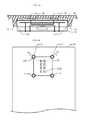
- FIG. 4Bis a plan view of the antenna device according to the third embodiment.
- a cross-sectional view taken along the dashed line 4 A- 4 A in FIG. 4Bcorresponds to the cross-sectional view of FIG. 4A .
- the antenna module 20has a substantially rectangular planar shape.
- the projections 11 provided on the inner surface of the radome 10are disposed at positions corresponding to the four corners of the antenna module 20 .
- the four corners of the antenna module 20are chamfered so as to fit the step surfaces 11 A ( FIG. 4A ) of the projections 11 . Surfaces that appear by chamfering the four corners of the antenna module 20 are in contact with the step surfaces 11 A of the projections 11 .
- the step surfaces 11 Arestrict the position of the antenna module 20 in the in-plane direction. Accordingly, it is possible to easily position the antenna module 20 relative to the radome 10 . As a result, it is possible to easily position the feed elements 22 and the parasitic elements 12 .
- FIG. 5Ais a plan view of an antenna device according to a first modification of the third embodiment.
- the projections 11FIG. 4B
- the step surfaces of two projections 11are in contact with one edge of the antenna module 20
- the step surface of another projection 11is in contact with an adjacent edge of the antenna module 20 . Even when the edge of the antenna module 20 is brought into contact with the step surfaces at three locations as described above, it is possible to restrict the position of the antenna module 20 relative to the radome 10 in the in-plane direction.
- FIG. 5Bis a perspective view before an antenna device according to a second modification of the third embodiment is assembled.
- a recess 13is provided in the inner surface of the radome 10 instead of the projections ( FIGS. 4A and 4B ) of the third embodiment.
- the planar shape of the recess 13substantially coincides with the planar shape of the antenna module 20 .
- the parasitic elements 12are disposed on the bottom surface of the recess 13 .
Landscapes
- Physics & Mathematics (AREA)
- Electromagnetism (AREA)
- Details Of Aerials (AREA)
- Variable-Direction Aerials And Aerial Arrays (AREA)
- Support Of Aerials (AREA)
Abstract
Description
- This application claims priority from Japanese Patent Application No. JP2017-016450 filed on Feb. 1, 2017. The content of this application is incorporated herein by reference in its entirety.
- The present disclosure relates to an antenna device and a method for manufacturing the antenna device.
- A wireless device has been known which includes a substrate, a wireless module that is mounted on the substrate, and a housing that houses the substrate and the wireless module (Japanese Unexamined Patent Application Publication No. 2015-8410). At the housing side from an antenna portion of the wireless module, a void having a length that is substantially equal to a multiple of a half wavelength of radio waves corresponding to a communication frequency of the antenna portion is ensured.
- A stack type microstrip antenna including a passive element (parasitic element) above a driven element (feed element) of the microstrip antenna has been known (see Japanese Unexamined Patent Application Publication No. 03-74908). The parasitic element is attached to the inner surface of a radome that covers the entirety of the antenna or embedded within the radome. The driven element is mounted on a metal base, and the radome is mounted on the metal base so as to cover the driven element.
- In the wireless device disclosed in Japanese Unexamined Patent Application Publication No. 2015-8410, it is necessary to ensure a void between the wireless module and the housing, and thus it is difficult to reduce the thickness of the wireless device. In the stack type microstrip antenna disclosed in Japanese Unexamined Patent Application Publication No. 03-74908, both the driven element and the radome are fixed to the metal base. In a step of mounting the driven element to the metal base and a step of mounting the radome to the metal base, alignment has to be performed such that the central axis of the driven element and the central axis of a parasitic element provided on the radome coincide with each other. If displacement occurs either in the step of mounting the driven element to the metal base or in the step of mounting the radome to the metal base, displacement occurs between the driven element and the parasitic element.
- Accordingly, it is an object of the present disclosure to provide an antenna device that is suitable for thickness reduction of the device and in which displacement less likely to occur between a feed element and a parasitic element.
- An antenna device according to a first aspect of the present disclosure includes:
- an antenna module including a dielectric substrate and a feed element provided on, in, or above the dielectric substrate;
- a radome comprising a dielectric and disposed so as to oppose the antenna module in a radiation direction of the feed element;
- a parasitic element provided at a position on the radome at which electromagnetic coupling with the feed element is achieved; and
- an adhesive layer disposed between the antenna module and the radome to bond the antenna module to the radome.
- Since the parasitic element is provided on the radome and the radome and the antenna module are bonded to each other by the adhesive layer, the adhesive layer is interposed between the feed element of the antenna module and the parasitic element provided on the radome. It is possible to make the feed element and the parasitic element closer to each other as compared to a configuration in which a void is ensured therebetween, and thus it is possible to reduce the thickness of the antenna device.
- Since the antenna module is directly bonded to the radome by the adhesive layer, displacement between the feed element of the antenna module and the parasitic element provided on the radome is less likely to occur, as compared to a configuration in which the antenna module and the radome are mounted to a common base member.
- In an antenna device according to a second aspect of the present disclosure, in addition to the configuration of the antenna device according to the first aspect, the adhesive layer has a lower dielectric constant than the dielectric substrate.
- It is possible to weaken electromagnetic coupling between the feed element and the parasitic element.
- In an antenna device according to a third aspect of the present disclosure, in addition to the configurations of the antenna devices according to the first and second aspects,
- the feed element of the antenna module is provided on a surface of the dielectric substrate, and the antenna module further includes a dielectric layer covering the surface of the dielectric substrate and the feed element, and
- the dielectric layer is bonded to the radome by the adhesive layer.
- The interval between the feed element and the parasitic element is large as compared to the case where the dielectric layer is not disposed. As a result, it is possible to weaken electromagnetic coupling between the feed element and the parasitic element.
- In an antenna device according to a fourth aspect of the present disclosure, in addition to the configurations of the antenna devices according to the first to third aspects, a step surface restricting a position of the antenna module in an in-plane direction is provided on an inner surface of the radome.
- In a step of bonding the antenna module to the radome, it is possible to easily position the antenna module relative to the radome.
- In an antenna device according to a fifth aspect of the present disclosure, in addition to the configurations of the antenna devices according to the first to fourth aspects, the radome also serves as a housing which houses the antenna module.
- Since the radome also serves as a housing, it is possible to reduce the number of components and also further reduce the thickness of the antenna device.
- In an antenna device according to a sixth aspect of the present disclosure, in addition to the configurations of the antenna devices according to the first to fifth aspects,
- the antenna module includes a plurality of other feed elements provided on the dielectric substrate in addition to the feed element, and the plurality of the other feed elements constitutes an array antenna, and
- a plurality of other parasitic elements are provided in, on, or above the radome in addition to the parasitic element, and the plurality of the other parasitic elements are electromagnetically coupled with the plurality of the other feed elements, respectively.
- Even in the case where a plurality of feed elements and a plurality of parasitic elements are disposed, alignment thereof is easily performed, since displacement between the feed element of the antenna module and the parasitic element provided on the radome is less likely to occur.
- A method for producing an antenna device according to a seventh aspect of the present disclosure includes the steps of:
- preparing an antenna module including a dielectric substrate and a feed element provided on the dielectric substrate;
- preparing a radome on which a parasitic element is provided and which is larger than the antenna module in a plan view; and
- positioning and bonding the antenna module to the radome such that the feed element and the parasitic element are electromagnetically coupled with each other.
- Since the antenna module including the feed element is bonded to the radome on which the parasitic element is provided, the adhesive layer is interposed between the feed element of the antenna module and the parasitic element provided on the radome. It is possible to make the feed element and the parasitic element closer to each other as compared to a configuration in which a void is ensured therebetween, and thus it is possible to reduce the thickness of the antenna device.
- Since the antenna module is directly bonded to the radome by the adhesive layer, displacement between the feed element of the antenna module and the parasitic element provided on the radome is less likely to occur, as compared to a method in which the antenna module and the radome are mounted to a common base member.
- Other features, elements, characteristics and advantages of the present disclosure will become more apparent from the following detailed description of preferred embodiments of the present disclosure (with reference to the attached drawings).
FIG. 1A is a partial cross-sectional view of a radome and parasitic elements used in an antenna device according to a first embodiment;FIG. 1B is a cross-sectional view of an antenna module used in the antenna device according to the first embodiment;FIG. 1C is a cross-sectional view of the antenna device in a state where the radome and the antenna module are bonded to each other;FIG. 1D is a plan view of the antenna device;FIG. 2 is a cross-sectional view of an antenna device according to a modification of the first embodiment;FIG. 3A is a cross-sectional view of an antenna module used in an antenna device according to a second embodiment;FIG. 3B is a cross-sectional view of the antenna device according to the second embodiment;FIG. 4A is a cross-sectional view of an antenna device according to a third embodiment;FIG. 4B is a plan view of the antenna device according to the third embodiment;FIG. 5A is a plan view of an antenna device according to a first modification of the third embodiment; andFIG. 5B is a perspective view before an antenna device according to a second modification of the third embodiment is assembled.- An antenna device according to a first embodiment will be described with reference to
FIGS. 1A to 1D . FIG. 1A is a partial cross-sectional view of aradome 10 andparasitic elements 12 used in the antenna device according to the first embodiment. Theradome 10 is, for example, a plate-like member formed from a dielectric. A plurality ofparasitic elements 12 are provided on one surface (inner surface) of theradome 10.FIG. 1B is a cross-sectional view of anantenna module 20 used in the antenna device according to the first embodiment. A plurality offeed elements 22 are formed on one surface (first surface)21A of adielectric substrate 21. For example, patch antennas are used as thefeed elements 22. A high-frequency integratedcircuit element 30 is mounted on asecond surface 21B of thedielectric substrate 21 opposite to thefirst surface 21A. Aground plane 23 is disposed in an inner layer of thedielectric substrate 21.- Each of the plurality of
feed elements 22 is connected to a high-frequency signal terminal of the high-frequency integratedcircuit element 30 via atransmission line 24 provided within thedielectric substrate 21. Theground plane 23 is connected to a ground terminal of the high-frequency integratedcircuit element 30 via awire 25 provided within thedielectric substrate 21. - A plurality of
conductor columns 31 project from thesecond surface 21B of thedielectric substrate 21. The plurality ofconductor columns 31 and the high-frequency integratedcircuit element 30 are embedded within a sealingresin layer 40. Eachconductor column 31 reaches the surface of the sealingresin layer 40. A plurality oflands 41 are provided on the surface of the sealingresin layer 40 so as to correspond to the plurality ofconductor columns 31. Some of the terminals of the high-frequency integratedcircuit element 30 are connected to the corresponding lands41 viawires 26 within thedielectric substrate 21 and theconductor columns 31. Theground plane 23 is connected to thelands 41 for grounding viawires 27 within thedielectric substrate 21 and theconductor columns 31. FIG. 1C is a cross-sectional view of the antenna device in a state where theradome 10 and theantenna module 20 are bonded to each other. Theantenna module 20 and theradome 10 are bonded to each other by anadhesive layer 50 such that the surface (first surface 21A) of theantenna module 20 on which thefeed elements 22 are formed opposes the inner surface of theradome 10 on which theparasitic elements 12 are formed. In this manner, theradome 10 is disposed so as to be spaced apart from theantenna module 20 across a gap in a radiation direction of thefeed elements 22.- Each
feed element 22 is disposed so as to oppose the correspondingparasitic element 12, and eachparasitic element 12 is electromagnetically coupled with thecorresponding feed element 22. The dielectric constant of theadhesive layer 50 is lower than the dielectric constant of thedielectric substrate 21. FIG. 1D is a plan view of the antenna device. In the plan view, theradome 10 is larger than theantenna module 20, and theantenna module 20 is disposed within theradome 10. The plurality offeed elements 22 and the plurality ofparasitic elements 12 are disposed regularly within the surfaces, for example, in a matrix manner. The plurality offeed elements 22 and the plurality ofparasitic elements 12 constitutes an array antenna.- The
radome 10 has a function to protect theantenna module 20. When theantenna module 20 is provided in a portable terminal such as a smartphone or a tablet terminal, theradome 10 also serves as a housing of the portable terminal that houses theantenna module 20. - Next, advantageous effects of the first embodiment will be described. By electromagnetically coupling the
parasitic elements 12 with thefeed elements 22, it is possible to widen the band of the antenna device. By adjusting the thickness of theadhesive layer 50, it is possible to accurately control the strength of the electromagnetic coupling between thefeed elements 22 and theparasitic elements 12. By making the dielectric constant of theadhesive layer 50 lower than the dielectric constant of thedielectric substrate 21, it is possible to weaken the electromagnetic coupling between thefeed elements 22 and theparasitic elements 12. - In a structure in which a void is ensured between the
feed elements 22 and theparasitic elements 12, in order to prevent the contact between thefeed elements 22 and theparasitic elements 12, it is preferable to increase the interval therebetween to some extent. In the first embodiment, theadhesive layer 50, which is formed from a dielectric, is disposed between thefeed elements 22 and theparasitic elements 12. Thus, even when the interval between thefeed elements 22 and theparasitic elements 12 is decreased, the contact therebetween does not occur. Thus, in the first embodiment, it is possible to reduce the thickness of the antenna device as compared to the structure in which a void is ensured between thefeed elements 22 and theparasitic elements 12. - When the interval between the
feed elements 22 and theparasitic elements 12 is increased, the electromagnetic coupling between onefeed element 22 and theparasitic element 12 opposing to thefeed element 22 adjacent to the onefeed element 22 easily occurs. When thefeed element 22 and the adjacentparasitic element 12 are electromagnetically coupled with each other, desired antenna characteristics are not obtained. In the first embodiment, it is possible to make thefeed elements 22 and theparasitic elements 12 closer to each other, and thus the electromagnetic coupling between thefeed element 22 and the adjacentparasitic element 12 is less likely to occur. In order to inhibit the electromagnetic coupling between thefeed element 22 and the adjacentparasitic element 12, it is preferable to make the interval between eachfeed element 22 and eachparasitic element 12 smaller than the interval between theadjacent feed elements 22. - When a structure in which each of the
antenna module 20 and theradome 10 is fixed to another common base member is adopted, an error in positioning of theantenna module 20 and the base member and an error in positioning of theradome 10 and the base member are superimposed on an error in positioning of theantenna module 20 and theradome 10. In the first embodiment, since theantenna module 20 is directly positioned and fixed to theradome 10 via theadhesive layer 50, it is possible to reduce an error in positioning. - When a plurality of the
feed elements 22 and a plurality of theparasitic elements 12 are disposed to constitute an array antenna, it is possible to enhance the accuracy of alignment of thefeed elements 22 and theparasitic elements 12 corresponding to each other. - Next, a modification of the first embodiment will be described with reference to
FIG. 2 . FIG. 2 is a cross-sectional view of an antenna device according to the modification of the first embodiment. In the first embodiment, theparasitic elements 12 are provided on the inner surface of theradome 10. However, in the present modification, theparasitic elements 12 are embedded within theradome 10.- In the present modification, it is possible to increase the interval between the
feed elements 22 and theparasitic elements 12 as compared to the structure of the first embodiment. As a result, it is possible to weaken the electromagnetic coupling between thefeed elements 22 and theparasitic elements 12. Whether the structure of the first embodiment or the structure of the modification is adopted may be determined in accordance with a target magnitude for the electromagnetic coupling between thefeed elements 22 and theparasitic elements 12. - Next, an antenna device according to a second embodiment will be described with reference to
FIGS. 3A and 3B . Hereinafter, the description of the components common to the antenna device according to the first embodiment is omitted. FIG. 3A is a cross-sectional view of anantenna module 20 used in the antenna device according to the second embodiment. In the first embodiment, thefeed elements 22 of theantenna module 20 are exposed as shown inFIG. 1B before theantenna module 20 is bonded to theradome 10. In the second embodiment, thefirst surface 21A of thedielectric substrate 21 and thefeed elements 22 are covered with adielectric layer 28. As described above, thefeed elements 22 are disposed in an inner layer of theantenna module 20, not on the surface of theantenna module 20.FIG. 3B is a cross-sectional view of the antenna device according to the second embodiment. Theadhesive layer 50 is disposed between thedielectric layer 28 of theantenna module 20 and theradome 10. Theantenna module 20 is bonded to theradome 10 by theadhesive layer 50 similarly to the first embodiment.- In the second embodiment, the strength of the electromagnetic coupling between the
feed elements 22 and theparasitic elements 12 depends not only on the dielectric constant and the thickness of theadhesive layer 50 but also on the dielectric constant and the thickness of thedielectric layer 28. Thus, the flexibility in adjusting the strength of the electromagnetic coupling between thefeed elements 22 and theparasitic elements 12 is increased. - In the second embodiment as well, the
parasitic elements 12 may be embedded within theradome 10 as in the modification of the first embodiment shown inFIG. 2 . - Next, an antenna device according to a third embodiment will be described with reference to
FIGS. 4A and 4B . Hereinafter, the description of the components common to the antenna device according to the first embodiment is omitted. FIG. 4A is a cross-sectional view of the antenna device according to the third embodiment. In the third embodiment,projections 11 are provided on the inner surface of theradome 10. Theantenna module 20 is in contact with the side surfaces (step surfaces)11A of theprojections 11.FIG. 4B is a plan view of the antenna device according to the third embodiment. A cross-sectional view taken along the dashedline 4A-4A inFIG. 4B corresponds to the cross-sectional view ofFIG. 4A . Theantenna module 20 has a substantially rectangular planar shape. Theprojections 11 provided on the inner surface of theradome 10 are disposed at positions corresponding to the four corners of theantenna module 20. The four corners of theantenna module 20 are chamfered so as to fit the step surfaces11A (FIG. 4A ) of theprojections 11. Surfaces that appear by chamfering the four corners of theantenna module 20 are in contact with the step surfaces11A of theprojections 11.- In the third embodiment, by the
antenna module 20 being brought into contact with the step surfaces11A of theradome 10, the step surfaces11A restrict the position of theantenna module 20 in the in-plane direction. Accordingly, it is possible to easily position theantenna module 20 relative to theradome 10. As a result, it is possible to easily position thefeed elements 22 and theparasitic elements 12. - Next, modifications of the third embodiment will be described with reference to
FIGS. 5A and 5B . FIG. 5A is a plan view of an antenna device according to a first modification of the third embodiment. In the third embodiment, the projections11 (FIG. 4B ) are disposed in corresponding relation to the four corners of theantenna module 20. However, in the first modification, the step surfaces of twoprojections 11 are in contact with one edge of theantenna module 20, and the step surface of anotherprojection 11 is in contact with an adjacent edge of theantenna module 20. Even when the edge of theantenna module 20 is brought into contact with the step surfaces at three locations as described above, it is possible to restrict the position of theantenna module 20 relative to theradome 10 in the in-plane direction.FIG. 5B is a perspective view before an antenna device according to a second modification of the third embodiment is assembled. In the second modification, arecess 13 is provided in the inner surface of theradome 10 instead of the projections (FIGS. 4A and 4B ) of the third embodiment. The planar shape of therecess 13 substantially coincides with the planar shape of theantenna module 20. Theparasitic elements 12 are disposed on the bottom surface of therecess 13. By disposing theantenna module 20 within therecess 13 and bringing theantenna module 20 into contact with the side surface (step surface)13A of therecess 13, it is possible to restrict the position of theantenna module 20 relative to theradome 10 in the in-plane direction.- Each embodiment is illustrative, and it is needless to say that the components shown in the different embodiments may be partially replaced or combined. The same advantageous effects achieved by the same configuration in multiple embodiments are not mentioned successively in each embodiment. Furthermore, the present disclosure is not limited to the above-described embodiments. For example, it is obvious to a person skilled in the art that various changes, modifications, combinations, etc. may be made.
- While preferred embodiments of the disclosure have been described above, it is to be understood that variations and modifications will be apparent to those skilled in the art without departing from the scope and spirit of the disclosure. The scope of the disclosure, therefore, is to be determined solely by the following claims.
Claims (17)
Applications Claiming Priority (2)
| Application Number | Priority Date | Filing Date | Title |
|---|---|---|---|
| JP2017016450AJP6597659B2 (en) | 2017-02-01 | 2017-02-01 | ANTENNA DEVICE AND ANTENNA DEVICE MANUFACTURING METHOD |
| JP2017-016450 | 2017-02-01 |
Publications (1)
| Publication Number | Publication Date |
|---|---|
| US20180219281A1true US20180219281A1 (en) | 2018-08-02 |
Family
ID=62980194
Family Applications (1)
| Application Number | Title | Priority Date | Filing Date |
|---|---|---|---|
| US15/886,117AbandonedUS20180219281A1 (en) | 2017-02-01 | 2018-02-01 | Antenna device and method for manufacturing antenna device |
Country Status (4)
| Country | Link |
|---|---|
| US (1) | US20180219281A1 (en) |
| JP (1) | JP6597659B2 (en) |
| KR (1) | KR101982030B1 (en) |
| CN (1) | CN108376833B (en) |
Cited By (19)
| Publication number | Priority date | Publication date | Assignee | Title |
|---|---|---|---|---|
| CN110350304A (en)* | 2019-06-30 | 2019-10-18 | 瑞声光电科技(苏州)有限公司 | The production method of antenna oscillator and antenna oscillator |
| WO2020096093A1 (en)* | 2018-11-09 | 2020-05-14 | Samsung Electronics Co., Ltd. | A patch antenna structure, an antenna feeder plate and a base station transceiver |
| CN112534642A (en)* | 2018-08-06 | 2021-03-19 | 株式会社村田制作所 | Antenna module |
| US20210351501A1 (en)* | 2020-05-08 | 2021-11-11 | W. L. Gore & Associates, Inc. | Assembly with at least one antenna and a thermal insulation component |
| US11223133B2 (en) | 2019-04-18 | 2022-01-11 | Samsung Electro-Mechanics Co., Ltd. | Chip antenna |
| US11233336B2 (en) | 2019-02-08 | 2022-01-25 | Samsung Electro-Mechanics Co., Ltd. | Chip antenna and chip antenna module including the same |
| US11251518B2 (en) | 2019-08-02 | 2022-02-15 | Samsung Electro-Mechanics Co., Ltd. | Chip antenna |
| US20220173506A1 (en)* | 2019-09-26 | 2022-06-02 | Murata Manufacturing Co., Ltd. | Antenna installation structure and electronic device |
| US20220224021A1 (en)* | 2021-01-12 | 2022-07-14 | Samsung Electronics Co., Ltd. | Antenna and electronic device including the same |
| US11417959B2 (en) | 2019-04-11 | 2022-08-16 | Samsung Electro-Mechanics Co., Ltd. | Chip antenna module and electronic device |
| US11431107B2 (en)* | 2019-04-11 | 2022-08-30 | Samsung Electro-Mechanics Co., Ltd. | Chip antenna module and method of manufacturing chip antenna module |
| US11437732B2 (en)* | 2019-09-17 | 2022-09-06 | Raytheon Company | Modular and stackable antenna array |
| EP3907823A4 (en)* | 2019-04-18 | 2022-09-28 | Fujikura Ltd. | ANTENNA |
| US20230062765A1 (en)* | 2021-08-26 | 2023-03-02 | Samsung Electronics Co., Ltd. | Antenna and electronic device including same |
| US11870164B2 (en) | 2019-01-10 | 2024-01-09 | Murata Manufacturing Co., Ltd. | Antenna module and communication device equipped with the same |
| US11962099B2 (en) | 2018-12-28 | 2024-04-16 | Vivo Mobile Communication Co., Ltd. | Antenna structure and high-frequency multi-band wireless communication terminal |
| US12142851B2 (en) | 2022-05-16 | 2024-11-12 | Raytheon Company | Low-profile circularly-polarized antenna |
| EP4354658A4 (en)* | 2021-06-11 | 2025-05-21 | LG Innotek Co., Ltd. | ANTENNA MODULE |
| US12334651B2 (en) | 2020-04-21 | 2025-06-17 | Samsung Electronics Co., Ltd. | Antenna device including radome and base station including antenna device |
Families Citing this family (12)
| Publication number | Priority date | Publication date | Assignee | Title |
|---|---|---|---|---|
| CN109728405B (en)* | 2018-12-28 | 2022-03-01 | 维沃移动通信有限公司 | Antenna structure and high frequency wireless communication terminal |
| KR102185048B1 (en)* | 2019-02-08 | 2020-12-01 | 삼성전기주식회사 | Chip antenna and chip antenna module including the same |
| WO2020184800A1 (en)* | 2019-03-08 | 2020-09-17 | 주식회사 파트론 | Electronic device |
| CN111725623B (en)* | 2019-03-20 | 2024-06-28 | 三星电机株式会社 | Chip antenna module and electronic device |
| KR102166126B1 (en)* | 2019-04-11 | 2020-10-15 | 삼성전기주식회사 | Chip antenna module and electronic device including thereof |
| KR102283085B1 (en)* | 2019-04-18 | 2021-07-29 | 삼성전기주식회사 | Chip antenna |
| CN110519424A (en)* | 2019-08-20 | 2019-11-29 | Oppo广东移动通信有限公司 | Electronic equipment's casing and electronic equipment |
| JP7370829B2 (en)* | 2019-11-28 | 2023-10-30 | 日立Astemo株式会社 | Millimeter wave radio sensor and vehicle equipped with it |
| KR102254880B1 (en)* | 2019-12-06 | 2021-05-24 | 삼성전기주식회사 | Chip antenna module array and chip antenna module |
| KR102762868B1 (en)* | 2020-04-14 | 2025-02-07 | 삼성전기주식회사 | Antenna |
| KR20230030813A (en)* | 2021-08-26 | 2023-03-07 | 삼성전자주식회사 | Antenna and electronic device including the same |
| EP4579951A1 (en)* | 2022-09-27 | 2025-07-02 | Samsung Electronics Co., Ltd. | Electronic device comprising antenna |
Citations (17)
| Publication number | Priority date | Publication date | Assignee | Title |
|---|---|---|---|---|
| US374908A (en)* | 1887-12-13 | Corporated | ||
| US4660047A (en)* | 1984-10-12 | 1987-04-21 | Itt Corporation | Microstrip antenna with resonator feed |
| US4835538A (en)* | 1987-01-15 | 1989-05-30 | Ball Corporation | Three resonator parasitically coupled microstrip antenna array element |
| US5977710A (en)* | 1996-03-11 | 1999-11-02 | Nec Corporation | Patch antenna and method for making the same |
| US6069590A (en)* | 1998-02-20 | 2000-05-30 | Ems Technologies, Inc. | System and method for increasing the isolation characteristic of an antenna |
| US20010043157A1 (en)* | 1999-01-25 | 2001-11-22 | Luk Kwai Man | Wideband patch antenna with L-shaped probe |
| US6333719B1 (en)* | 1999-06-17 | 2001-12-25 | The Penn State Research Foundation | Tunable electromagnetic coupled antenna |
| JP2003283239A (en)* | 2002-03-20 | 2003-10-03 | Mitsubishi Electric Corp | Antenna device |
| US20070159380A1 (en)* | 2005-10-18 | 2007-07-12 | Hitachi, Ltd. | Millimeter-wave radar apparatus and millimeter radar system using the same |
| US20080252544A1 (en)* | 2007-04-12 | 2008-10-16 | Irion James M | Low Profile Antenna |
| US20080316112A1 (en)* | 2006-01-17 | 2008-12-25 | Yue Ping Zhang | Antennas |
| US20100193935A1 (en)* | 2009-01-30 | 2010-08-05 | Infineon Technologies Ag | Integrated antennas in wafer level package |
| US20120287019A1 (en)* | 2010-01-27 | 2012-11-15 | Murata Manufacturing Co., Ltd. | Wideband antenna |
| US20150249283A1 (en)* | 2013-06-25 | 2015-09-03 | Panasonic Intellectual Property Management Co., Ltd. | Wireless module |
| US20160056544A1 (en)* | 2013-09-11 | 2016-02-25 | International Business Machines Corporation | Antenna-in-package structures with broadside and end-fire radiations |
| US20160365643A1 (en)* | 2014-03-03 | 2016-12-15 | Fujikura Ltd. | Microstrip antenna |
| US20170084988A1 (en)* | 2014-10-20 | 2017-03-23 | The Boeing Company | Antenna Electromagnetic Radiation Steering System |
Family Cites Families (11)
| Publication number | Priority date | Publication date | Assignee | Title |
|---|---|---|---|---|
| JPH0374908A (en)* | 1989-08-16 | 1991-03-29 | Toyo Commun Equip Co Ltd | Microstrip antenna of stack type |
| JPH05121931A (en)* | 1991-10-26 | 1993-05-18 | Nec Corp | Plane antenna |
| KR100449846B1 (en)* | 2001-12-26 | 2004-09-22 | 한국전자통신연구원 | Circular Polarized Microstrip Patch Antenna and Array Antenna arraying it for Sequential Rotation Feeding |
| EP1603188B1 (en)* | 2004-06-02 | 2008-06-04 | Sony Ericsson Mobile Communications AB | Transparent conductive antenna for a portable communication device |
| JP2006121406A (en)* | 2004-10-21 | 2006-05-11 | Nippon Dengyo Kosaku Co Ltd | Array antenna |
| KR100608832B1 (en)* | 2004-11-12 | 2006-08-09 | 엘지전자 주식회사 | Multi socket of portable terminal |
| KR100820758B1 (en)* | 2005-01-21 | 2008-04-10 | (주)지컨 | Patch Type Dual Antenna |
| JP5669773B2 (en)* | 2012-02-24 | 2015-02-18 | 三菱電機株式会社 | Curved substrate and method of manufacturing curved substrate |
| US9520655B2 (en)* | 2014-05-29 | 2016-12-13 | University Corporation For Atmospheric Research | Dual-polarized radiating patch antenna |
| CN204179222U (en)* | 2014-11-15 | 2015-02-25 | 中国航天科工集团第三研究院第八三五七研究所 | Double-layer wideband directional diagram tiltedly refers to antenna |
| CN105846051A (en)* | 2016-05-13 | 2016-08-10 | 深圳三星通信技术研究有限公司 | Method for reducing height of base station antenna, and base station antenna |
- 2017
- 2017-02-01JPJP2017016450Apatent/JP6597659B2/enactiveActive
- 2017-12-29KRKR1020170183333Apatent/KR101982030B1/enactiveActive
- 2018
- 2018-01-30CNCN201810089071.1Apatent/CN108376833B/enactiveActive
- 2018-02-01USUS15/886,117patent/US20180219281A1/ennot_activeAbandoned
Patent Citations (17)
| Publication number | Priority date | Publication date | Assignee | Title |
|---|---|---|---|---|
| US374908A (en)* | 1887-12-13 | Corporated | ||
| US4660047A (en)* | 1984-10-12 | 1987-04-21 | Itt Corporation | Microstrip antenna with resonator feed |
| US4835538A (en)* | 1987-01-15 | 1989-05-30 | Ball Corporation | Three resonator parasitically coupled microstrip antenna array element |
| US5977710A (en)* | 1996-03-11 | 1999-11-02 | Nec Corporation | Patch antenna and method for making the same |
| US6069590A (en)* | 1998-02-20 | 2000-05-30 | Ems Technologies, Inc. | System and method for increasing the isolation characteristic of an antenna |
| US20010043157A1 (en)* | 1999-01-25 | 2001-11-22 | Luk Kwai Man | Wideband patch antenna with L-shaped probe |
| US6333719B1 (en)* | 1999-06-17 | 2001-12-25 | The Penn State Research Foundation | Tunable electromagnetic coupled antenna |
| JP2003283239A (en)* | 2002-03-20 | 2003-10-03 | Mitsubishi Electric Corp | Antenna device |
| US20070159380A1 (en)* | 2005-10-18 | 2007-07-12 | Hitachi, Ltd. | Millimeter-wave radar apparatus and millimeter radar system using the same |
| US20080316112A1 (en)* | 2006-01-17 | 2008-12-25 | Yue Ping Zhang | Antennas |
| US20080252544A1 (en)* | 2007-04-12 | 2008-10-16 | Irion James M | Low Profile Antenna |
| US20100193935A1 (en)* | 2009-01-30 | 2010-08-05 | Infineon Technologies Ag | Integrated antennas in wafer level package |
| US20120287019A1 (en)* | 2010-01-27 | 2012-11-15 | Murata Manufacturing Co., Ltd. | Wideband antenna |
| US20150249283A1 (en)* | 2013-06-25 | 2015-09-03 | Panasonic Intellectual Property Management Co., Ltd. | Wireless module |
| US20160056544A1 (en)* | 2013-09-11 | 2016-02-25 | International Business Machines Corporation | Antenna-in-package structures with broadside and end-fire radiations |
| US20160365643A1 (en)* | 2014-03-03 | 2016-12-15 | Fujikura Ltd. | Microstrip antenna |
| US20170084988A1 (en)* | 2014-10-20 | 2017-03-23 | The Boeing Company | Antenna Electromagnetic Radiation Steering System |
Cited By (26)
| Publication number | Priority date | Publication date | Assignee | Title |
|---|---|---|---|---|
| CN112534642A (en)* | 2018-08-06 | 2021-03-19 | 株式会社村田制作所 | Antenna module |
| WO2020096093A1 (en)* | 2018-11-09 | 2020-05-14 | Samsung Electronics Co., Ltd. | A patch antenna structure, an antenna feeder plate and a base station transceiver |
| US11923623B2 (en) | 2018-11-09 | 2024-03-05 | Samsung Electronics Co., Ltd. | Patch antenna structure, an antenna feeder plate and a base station transceiver |
| US11962099B2 (en) | 2018-12-28 | 2024-04-16 | Vivo Mobile Communication Co., Ltd. | Antenna structure and high-frequency multi-band wireless communication terminal |
| US11870164B2 (en) | 2019-01-10 | 2024-01-09 | Murata Manufacturing Co., Ltd. | Antenna module and communication device equipped with the same |
| US11233336B2 (en) | 2019-02-08 | 2022-01-25 | Samsung Electro-Mechanics Co., Ltd. | Chip antenna and chip antenna module including the same |
| US11417959B2 (en) | 2019-04-11 | 2022-08-16 | Samsung Electro-Mechanics Co., Ltd. | Chip antenna module and electronic device |
| US11431107B2 (en)* | 2019-04-11 | 2022-08-30 | Samsung Electro-Mechanics Co., Ltd. | Chip antenna module and method of manufacturing chip antenna module |
| EP3907823A4 (en)* | 2019-04-18 | 2022-09-28 | Fujikura Ltd. | ANTENNA |
| US11621491B2 (en) | 2019-04-18 | 2023-04-04 | Samsung Electro-Mechanics Co., Ltd. | Chip antenna |
| US11223133B2 (en) | 2019-04-18 | 2022-01-11 | Samsung Electro-Mechanics Co., Ltd. | Chip antenna |
| US11658419B2 (en) | 2019-04-18 | 2023-05-23 | Fujikura Ltd. | Antenna formed on flexible dielectric laminated body |
| CN110350304A (en)* | 2019-06-30 | 2019-10-18 | 瑞声光电科技(苏州)有限公司 | The production method of antenna oscillator and antenna oscillator |
| US11251518B2 (en) | 2019-08-02 | 2022-02-15 | Samsung Electro-Mechanics Co., Ltd. | Chip antenna |
| US11437732B2 (en)* | 2019-09-17 | 2022-09-06 | Raytheon Company | Modular and stackable antenna array |
| US20220173506A1 (en)* | 2019-09-26 | 2022-06-02 | Murata Manufacturing Co., Ltd. | Antenna installation structure and electronic device |
| US12009588B2 (en)* | 2019-09-26 | 2024-06-11 | Murata Manufacturing Co., Ltd. | Antenna installation structure and electronic device |
| US12334651B2 (en) | 2020-04-21 | 2025-06-17 | Samsung Electronics Co., Ltd. | Antenna device including radome and base station including antenna device |
| US12237574B2 (en)* | 2020-05-08 | 2025-02-25 | W. L. Gore & Associates, Inc. | Assembly with at least one antenna and a thermal insulation component |
| US20210351501A1 (en)* | 2020-05-08 | 2021-11-11 | W. L. Gore & Associates, Inc. | Assembly with at least one antenna and a thermal insulation component |
| US20220224021A1 (en)* | 2021-01-12 | 2022-07-14 | Samsung Electronics Co., Ltd. | Antenna and electronic device including the same |
| US12206175B2 (en)* | 2021-01-12 | 2025-01-21 | Samsung Electronics Co., Ltd. | Antenna and electronic device including the same |
| EP4354658A4 (en)* | 2021-06-11 | 2025-05-21 | LG Innotek Co., Ltd. | ANTENNA MODULE |
| US20230062765A1 (en)* | 2021-08-26 | 2023-03-02 | Samsung Electronics Co., Ltd. | Antenna and electronic device including same |
| US12191576B2 (en)* | 2021-08-26 | 2025-01-07 | Samsung Electronics Co., Ltd. | Antenna and electronic device including same |
| US12142851B2 (en) | 2022-05-16 | 2024-11-12 | Raytheon Company | Low-profile circularly-polarized antenna |
Also Published As
| Publication number | Publication date |
|---|---|
| JP6597659B2 (en) | 2019-10-30 |
| CN108376833A (en) | 2018-08-07 |
| KR20180089853A (en) | 2018-08-09 |
| JP2018125704A (en) | 2018-08-09 |
| CN108376833B (en) | 2021-11-05 |
| KR101982030B1 (en) | 2019-05-24 |
Similar Documents
| Publication | Publication Date | Title |
|---|---|---|
| US20180219281A1 (en) | Antenna device and method for manufacturing antenna device | |
| US9048542B2 (en) | Side-face radiation antenna and wireless communication module | |
| CN104051440B (en) | Semiconductor structure with antenna | |
| US7026999B2 (en) | Pattern antenna | |
| CN102881986A (en) | Semiconductor package | |
| JP7238755B2 (en) | Antenna device, antenna module, and communication device | |
| CN103650132A (en) | Wireless module | |
| JP2002368532A (en) | Micro-strip antenna and its forming method | |
| US6975272B2 (en) | Circularly polarized wave antenna device suitable for miniaturization | |
| CN108269790B (en) | Packaged device with integrated antenna | |
| KR102493417B1 (en) | Stacked patch antenna | |
| US10784562B2 (en) | Wireless communication chip having internal antenna, internal antenna for wireless communication chip, and method of fabricating wireless communication chip having internal antenna | |
| US7663568B2 (en) | Antenna apparatus | |
| JP2007013857A (en) | Planar antenna system | |
| KR102363473B1 (en) | Communication module package | |
| KR20220072667A (en) | Communication module package | |
| CN108538823B (en) | Packaging chip of integrated monopole antenna and processing method thereof | |
| JP7366148B2 (en) | RFID tag | |
| JP7124986B2 (en) | wireless communication module | |
| KR102605605B1 (en) | Communication module package | |
| KR102569383B1 (en) | Electronic device | |
| JP5873350B2 (en) | Wireless module with integrated antenna | |
| US20220255180A1 (en) | Electronic device | |
| US20240364022A1 (en) | Antenna module | |
| KR102209674B1 (en) | Electronic device having antenna |
Legal Events
| Date | Code | Title | Description |
|---|---|---|---|
| AS | Assignment | Owner name:MURATA MANUFACTURING CO., LTD., JAPAN Free format text:ASSIGNMENT OF ASSIGNORS INTEREST;ASSIGNORS:SUDO, KAORU;MIZUNUMA, RYUKEN;SIGNING DATES FROM 20180109 TO 20180117;REEL/FRAME:044799/0257 | |
| STPP | Information on status: patent application and granting procedure in general | Free format text:DOCKETED NEW CASE - READY FOR EXAMINATION | |
| STPP | Information on status: patent application and granting procedure in general | Free format text:NON FINAL ACTION MAILED | |
| STPP | Information on status: patent application and granting procedure in general | Free format text:RESPONSE TO NON-FINAL OFFICE ACTION ENTERED AND FORWARDED TO EXAMINER | |
| STPP | Information on status: patent application and granting procedure in general | Free format text:FINAL REJECTION MAILED | |
| STPP | Information on status: patent application and granting procedure in general | Free format text:DOCKETED NEW CASE - READY FOR EXAMINATION | |
| STPP | Information on status: patent application and granting procedure in general | Free format text:DOCKETED NEW CASE - READY FOR EXAMINATION | |
| STPP | Information on status: patent application and granting procedure in general | Free format text:NON FINAL ACTION MAILED | |
| STPP | Information on status: patent application and granting procedure in general | Free format text:RESPONSE TO NON-FINAL OFFICE ACTION ENTERED AND FORWARDED TO EXAMINER | |
| STPP | Information on status: patent application and granting procedure in general | Free format text:FINAL REJECTION MAILED | |
| STCB | Information on status: application discontinuation | Free format text:ABANDONED -- FAILURE TO RESPOND TO AN OFFICE ACTION |