US20180156302A1 - Hydraulic damper with a compression stop - Google Patents
Hydraulic damper with a compression stopDownload PDFInfo
- Publication number
- US20180156302A1 US20180156302A1US15/816,615US201715816615AUS2018156302A1US 20180156302 A1US20180156302 A1US 20180156302A1US 201715816615 AUS201715816615 AUS 201715816615AUS 2018156302 A1US2018156302 A1US 2018156302A1
- Authority
- US
- United States
- Prior art keywords
- compression
- damper
- flow channel
- assembly
- rebound
- Prior art date
- Legal status (The legal status is an assumption and is not a legal conclusion. Google has not performed a legal analysis and makes no representation as to the accuracy of the status listed.)
- Granted
Links
- 230000006835compressionEffects0.000titleclaimsabstractdescription114
- 238000007906compressionMethods0.000titleclaimsabstractdescription114
- 238000006073displacement reactionMethods0.000claimsabstractdescription8
- 239000007788liquidSubstances0.000claimsdescription24
- 239000000725suspensionSubstances0.000claimsdescription3
- 238000013016dampingMethods0.000description12
- 230000000712assemblyEffects0.000description3
- 238000000429assemblyMethods0.000description3
- 238000010276constructionMethods0.000description3
- 230000036316preloadEffects0.000description2
- 238000007493shaping processMethods0.000description2
- 238000006243chemical reactionMethods0.000description1
- 238000010586diagramMethods0.000description1
- 230000003467diminishing effectEffects0.000description1
- 239000012530fluidSubstances0.000description1
- 239000000463materialSubstances0.000description1
- 230000004048modificationEffects0.000description1
- 238000012986modificationMethods0.000description1
- 238000000638solvent extractionMethods0.000description1
Images


Classifications
- F—MECHANICAL ENGINEERING; LIGHTING; HEATING; WEAPONS; BLASTING
- F16—ENGINEERING ELEMENTS AND UNITS; GENERAL MEASURES FOR PRODUCING AND MAINTAINING EFFECTIVE FUNCTIONING OF MACHINES OR INSTALLATIONS; THERMAL INSULATION IN GENERAL
- F16F—SPRINGS; SHOCK-ABSORBERS; MEANS FOR DAMPING VIBRATION
- F16F9/00—Springs, vibration-dampers, shock-absorbers, or similarly-constructed movement-dampers using a fluid or the equivalent as damping medium
- F16F9/32—Details
- F16F9/48—Arrangements for providing different damping effects at different parts of the stroke
- F16F9/49—Stops limiting fluid passage, e.g. hydraulic stops or elastomeric elements inside the cylinder which contribute to changes in fluid damping
- F—MECHANICAL ENGINEERING; LIGHTING; HEATING; WEAPONS; BLASTING
- F16—ENGINEERING ELEMENTS AND UNITS; GENERAL MEASURES FOR PRODUCING AND MAINTAINING EFFECTIVE FUNCTIONING OF MACHINES OR INSTALLATIONS; THERMAL INSULATION IN GENERAL
- F16F—SPRINGS; SHOCK-ABSORBERS; MEANS FOR DAMPING VIBRATION
- F16F9/00—Springs, vibration-dampers, shock-absorbers, or similarly-constructed movement-dampers using a fluid or the equivalent as damping medium
- F16F9/32—Details
- F16F9/58—Stroke limiting stops, e.g. arranged on the piston rod outside the cylinder
- F16F9/585—Stroke limiting stops, e.g. arranged on the piston rod outside the cylinder within the cylinder, in contact with working fluid
- F—MECHANICAL ENGINEERING; LIGHTING; HEATING; WEAPONS; BLASTING
- F16—ENGINEERING ELEMENTS AND UNITS; GENERAL MEASURES FOR PRODUCING AND MAINTAINING EFFECTIVE FUNCTIONING OF MACHINES OR INSTALLATIONS; THERMAL INSULATION IN GENERAL
- F16F—SPRINGS; SHOCK-ABSORBERS; MEANS FOR DAMPING VIBRATION
- F16F9/00—Springs, vibration-dampers, shock-absorbers, or similarly-constructed movement-dampers using a fluid or the equivalent as damping medium
- F16F9/10—Springs, vibration-dampers, shock-absorbers, or similarly-constructed movement-dampers using a fluid or the equivalent as damping medium using liquid only; using a fluid of which the nature is immaterial
- F16F9/14—Devices with one or more members, e.g. pistons, vanes, moving to and fro in chambers and using throttling effect
- F16F9/16—Devices with one or more members, e.g. pistons, vanes, moving to and fro in chambers and using throttling effect involving only straight-line movement of the effective parts
- F16F9/18—Devices with one or more members, e.g. pistons, vanes, moving to and fro in chambers and using throttling effect involving only straight-line movement of the effective parts with a closed cylinder and a piston separating two or more working spaces therein
- F16F9/185—Bitubular units
- F—MECHANICAL ENGINEERING; LIGHTING; HEATING; WEAPONS; BLASTING
- F16—ENGINEERING ELEMENTS AND UNITS; GENERAL MEASURES FOR PRODUCING AND MAINTAINING EFFECTIVE FUNCTIONING OF MACHINES OR INSTALLATIONS; THERMAL INSULATION IN GENERAL
- F16F—SPRINGS; SHOCK-ABSORBERS; MEANS FOR DAMPING VIBRATION
- F16F9/00—Springs, vibration-dampers, shock-absorbers, or similarly-constructed movement-dampers using a fluid or the equivalent as damping medium
- F16F9/32—Details
- F16F9/34—Special valve constructions; Shape or construction of throttling passages
- F—MECHANICAL ENGINEERING; LIGHTING; HEATING; WEAPONS; BLASTING
- F16—ENGINEERING ELEMENTS AND UNITS; GENERAL MEASURES FOR PRODUCING AND MAINTAINING EFFECTIVE FUNCTIONING OF MACHINES OR INSTALLATIONS; THERMAL INSULATION IN GENERAL
- F16F—SPRINGS; SHOCK-ABSORBERS; MEANS FOR DAMPING VIBRATION
- F16F2230/00—Purpose; Design features
- F16F2230/0052—Physically guiding or influencing
- F16F2230/0064—Physically guiding or influencing using a cam
Definitions
- the present inventionrelates to a hydraulic damper, in particular to a motor vehicle hydraulic suspension damper, comprising a tube filled with a working liquid, a piston assembly disposed slidably inside the tube, thereby dividing the tube into a rebound chamber and a compression chamber, provided with rebound and compression valve assemblies to control the flow of the working liquid within the tube during rebound and compression strokes of the damper, and attached to a piston rod led outside the damper, and a compression stop assembly located in the compression chamber.
- the compression stop assemblyprevents an abrupt stop of a piston at the end of the damper compression stroke by generating an additional damping force which increases progressively as the piston rod displaces.
- WO 2014/085954discloses a hydraulic damper with a compression stop assembly comprising a supporting member partitioning damper internal tube and provided with an axial opening and at least one passage for a substantially unobstructed flow of working liquid; an axial member disposed slidably within said axial opening; a rigid body fixed on said axial member and provided with at least one compression flow passage and at least one rebound flow passage; a compression stroke disc assembly comprising at least one deflective disc and normally covering the compression side of said rigid body; a rebound stroke disc assembly comprising at least one deflective disc and normally covering the rebound side of said rigid body; a first spring disposed between said supporting member and the compression side of said rigid body to normally press said axial member into the compression chamber; and a second spring secured to the rebound side of said rigid body.
- Such a constructionprovides versatile tuning opportunities for shaping damping force characteristics with regard to the position as well as the velocity of the piston rod combining both mechanical (springs), as well as hydraulic (flow passages) damping. Nonetheless this damping force may still become harsh at the position, in which the rigid body abruptly presses the supporting member allowing for a flow of working liquid solely through the compression disc assembly.
- U.S. Pat. No. 5,251,927discloses a hydraulic damper having a base valve assembly provided with a rotary plate having a plurality of openings corresponding to the base valve slots, rotatably connected on the base valve. Rotation of the plate selectively opens or covers up the slots with the openings to permit the fluid flow from the lower chamber to the base valve reservoir.
- the rotary plateis connected by an axial bore, a stem and an arm to a turnable steering knuckle assembly which enables varying the damping characteristics of the damper based on a steering motion of a vehicle's wheels.
- the inventionprovides, a damper of the kind mentioned in the outset provided with a compression stop assembly located in the compression chamber and comprising a body; an axial member disposed slidably within said body; a covering member fixed on said axial member and provided with at least one compression flow channel and at least one rebound flow channel; a disengaging spring preloaded between said body and said covering member, which according to the present invention is characterised in that said compression stop assembly further comprises a rotating member disposed pivotally with respect to said body and capable of covering at least partially said at least one compression flow channel depending on the angular position of said rotating member with respect to said at least one compression flow channel; and at least one cam configured to cooperate with said rotating member in order to change its angular position with respect to its axial displacement; wherein axial displacement of said covering member towards said body, while being engaged by the piston assembly results in covering said at least one compression flow channel by said rotating member.
- said compression stop assemblyis further provided with an engaging spring attached to said covering member and preferably terminated with an engaging bumper.
- the engaging springprovides gradual increase of the reaction force before the covering member rotation begins.
- Said compression stop assemblypreferably further comprises at least one, preferably deflective, disc covering compression side of said rebound flow channels and providing unrestricted inflow of the working liquid to the compression flow channels from the compression chamber.
- the discinitiates the rebound stroke of the compression stop assembly while in a fully engaged position.
- said rotating membercomprises at least one radial projection cooperating with said cam shaped, preferably spirally, in an inner annular surface of said body.
- Said rotating memberpreferably comprises at least one radial projection apt to cover said at least one compression flow channel. Projections provide yet another tuning option for the compression stop assembly.
- said covering memberpreferably comprises many, preferably equiangularly spaced, preferably slanted, compression flow channels separated with, preferably equiangularly spaced, preferably axial, rebound flow channels.
- the damperis a twin-tube damper.
- said body of said compression stop assemblypreferably has a form of a sleeve fixed between the compression end of the damper main tube and the damper base valve assembly and is provided with at least one channel enabling for a flow of working liquid between the compression chamber and a compensation chamber through the base valve assembly.
- said body of said compression stop assemblymay be itself a body of the damper base valve assembly.
- FIG. 1is a schematic cross-sectional view of a twin-tube damper according to the present invention with an embodiment of a compression stop assembly in a disengaged position;
- FIG. 2shows the compression stop assembly in an intermediate engaged position during a compression stroke of the damper
- FIG. 3shows the compression stop assembly in a fully engaged position
- FIG. 4is a schematic cross-sectional perspective view of a part of the compression stop assembly in a fully engaged position, at the beginning of the rebound stroke;
- FIG. 5is a schematic cross-sectional perspective view of a part of the compression stop assembly in a disengaged position
- FIG. 6is a schematic exploded perspective view of the compression stop assembly
- FIG. 7is a compression side view of the covering member
- FIG. 8is a compression side view of the rotating member
- FIG. 9is a compression side view of the body.
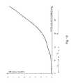
- FIG. 10is a diagram illustrating damping force versus piston rod displacement characteristics of the compression stop assembly shown in FIG. 1 .
- FIG. 1presents an embodiment of a twin-tube damper 1 according to the present invention that may be employed in a typical motor vehicle suspension.
- the damper 1comprises an external tube 2 and a main tube 3 filled with viscous working liquid inside of which a movable piston assembly 4 is disposed.
- the piston assembly 4is attached on an axial protrusion 51 of a piston rod 5 by means of a nut 52 and led outside the damper 1 through a sealed piston rod guide 6 .
- the damper 1is also provided with a base valve assembly 7 fixed at the other end of the main tube 3 .
- the piston assembly 4makes a sliding fit with the inner surface of the main tube 3 and divides the main tube 3 into a rebound chamber 11 , located between the piston rod guide 6 and the piston assembly 4 , and a compression chamber 12 located between the piston assembly 4 and the base valve assembly 7 .
- An additional compensation chamber 13is located at the other side of the base valve assembly 7 .
- compressionrefers to these elements or parts of elements which are adjacent to the compression chamber 12 or, in a case of working liquid flow direction, it refers to this flow direction that takes place during the compression stroke of the damper 1 .
- reboundrefers to these elements or these parts of particular elements which are adjacent to the rebound chamber 11 or, in a case of working liquid flow direction, it refers to this flow direction that takes place during the rebound stroke of the damper 1 .
- the piston assembly 4is provided with valve assemblies to control the flow of working liquid passing between the rebound chamber 11 and the compression chamber 12 while the piston assembly 4 is in motion.
- the base valve assembly 7is provided with valve assemblies to control the flow of working liquid passing between the compression chamber 12 and the compensation chamber 13 while the piston assembly 4 is in motion. Nonetheless, as shall be recognised by those skilled in the art from the following description, the invention is also applicable to other damper constructions.
- the damper 1further comprises a compression stop assembly 8 located in the compression chamber 12 .
- the compression stop assembly 8comprises a body 81 , an axial member 82 in a form of a bolt, a retaining member 83 , a rotating member 84 , a covering member 85 , a deflective disc 86 , a disengaging spring 87 , an engaging spring 88 , and an engaging bumper 89 .
- the body 81shown in particular in FIG. 9 , has a form of a sleeve fixed between the compression end of the main tube 3 and the base valve assembly 7 and is provided with six equiangularly spaced axially extending channels 811 (cf. FIG. 3 ) enabling for a flow of working liquid between the compression chamber 12 and the compensation chamber 13 through the base valve assembly 7 .
- the bolt 82passes slidably through an axial noncircular opening 814 in the body 81 so that its rotation is blocked.
- the opening 814is provided with a positioning surface 815 cooperating with a matching positioning surface 823 of the bolt 82 (cf. FIG. 4 ).
- the bolt 82is provided with an axial protrusion 821 of a narrowed diameter on which the retaining member 83 provided with a similar positioning surface 831 (cf. FIG. 6 ) matching the positioning surface 823 of the bolt 82 is fixed.
- the covering member 85is fixed on the retaining member 83 provided with two positioning projections 832 matching positioning recesses 857 of the covering member 85 .
- the deflective disc 86is disposed at the other side of the covering member 85 . Therefore the retaining member 83 , the covering member 85 and the disc 86 are secured on this axial protrusion 821 by means of a retainer 822 (a nut, a rivet or any other fixing mechanism might be obviously used in different embodiments) and may only perform a contracted sliding movement along with the bolt 82 in the opening 814 of the body.
- a retainer 822a nut, a rivet or any other fixing mechanism might be obviously used in different embodiments
- the covering member 85shown in particular in FIG. 7 , comprises eight equiangularly spaced slanted compression flow channels 853 joining its compression sides with its rebound side and separated with eight equiangularly spaced axial rebound flow channels 854 .
- the deflective disc 86covers the compression side of the rebound flow channels 854 but its deflection enables for a restricted flow of working liquid during the rebound stoke.
- the discis provided with two kidney-shaped internal openings 861 (cf. FIG. 6 ) connecting the compression chamber 12 with an annular recess 855 joining the inlets of the slanted compression flow channels 853 and enabling for an unrestricted inflow of the working liquid to these channels from the compression chamber 12 .
- Another annular recess 856joins the outlets of the axial rebound flow channels 854 equalizing pressure beneath the deflective disc 86 during the rebound stroke (cf. FIG. 4 ).
- the disengaging spring 87is preloaded between the body 81 and an annular projection 851 of the covering member 85 maintaining the extended position of these elements and defining an annular channel 852 in-between, while the compression stop assembly 8 is not in a fully engaged position shown in FIG. 3 .
- the engaging spring 88is fixed to the covering member 85 at the other side of its annular projection 851 and connected with the engaging bumper 89 at the other side.
- the rotating member 84is pivotally disposed on the retaining member 83 and comprises four equiangularly disposed radial and cylindrical projections 842 disposed in and cooperating with four cams 812 that are spirally shaped and in an inner annular surface 813 of the body 81 , as shall be explained later.
- the rotating member 84further comprises eight equiangularly disposed radial projections 843 adapted to cover the rebound sides or outlets of the slanted compression flow channels 853 of the covering member 85 . Nonetheless in a disengaged position of the compression stop assembly 8 shown in FIG. 1 the channels 853 remain uncovered by the covering projections 843 .
- the working liquidmay flow with no substantial restrictions both around the annular projection 851 and the annular channel 852 , as well as through the internal openings 861 of the deflective disc 86 and the slanted compression flow channels 853 of the covering member 85 .
- the piston assembly 4engages the engaging bumper 89 and starts compressing the engaging spring 88 so that the damping gradually increases as in typical spring compression stops known from the state of art.
- the load of the engaging spring 88equalizes the initial preload of the disengaging spring 87 forcing it to compress and axially displacing the covering member 85 along with the bolt 82 .
- This axial movementforces rotation of the rotating member 84 as each cylindrical projection 842 slides spirally in its cam 812 .
- the covering projections 843gradually cover the compression flow channels 853 of the covering member 85 .
- the working liquidmay flow out of the compression chamber 12 only around the annular projection 851 of the covering member 85 and the annular channel 852 .
- FIG. 4illustrates the compression stop assembly 8 in fully engaged position, at the beginning of the rebound stroke.
- the pressure of the working liquid flowing through the channels 811 in the body 81 , channels 841 in the rotating member 84 and axial rebound flow channel 854 of the covering member 85leads to deflecting the disc 86 and the compression stop assembly 8 will begin to displace towards the compression chamber under the pressure of the disengaging spring 87 .
- FIG. 10shows a damping force characteristics of the compression stop assembly 8 of the damper 1 shown in FIG. 1 and described above, as measured during compression stroke starting from the point where the piston assembly 4 engages the engaging bumper 89 (both piston rod displacement and damping force equal zero).
- the engaging spring 88compresses, thus linearly increasing the damping force.
- the load of the engaging spring 88equalizes the initial preload of the disengaging spring 87 and the latter compresses operating in series with the engaging spring 88 and axially displacing the covering member 85 along with the bolt 82 and further increasing the damping force within the second range R 2 .
- the rotating member 84rotates in cams 812 and its covering projections 843 gradually cover the compression flow channels 853 of the covering member 85 so that eventually only the diminishing annular channel 852 remains available for a flow of the working liquid until it is entirely closed.
- compression stop assemblymay obviously enable for a flow of working liquid even though the covering member 85 abuts the body 81 (cf. FIG. 3 , FIG. 4 ) by means of additional channels, annular gaps in the covering member 85 or the body 81 , etc.
- the number, thickness and/or material of the deflective discs 86 , the number and the cross-flow area of the channels 853 and 854 , axial stiffness of the engaging spring 88 , axial stiffness of the disengaging spring 87 , the shape of the cams 812 , the shape of the radial projections 843 covering the compression flow channels 853 , etc.all provide excellent capabilities for setting various thresholds and flow restrictions to be generated for working liquid passing through the compression stop assembly 8 while being engaged by the piston assembly 4 . This in turn provides virtually unlimited capabilities for shaping and tuning a preferable damping force characteristics of the compression stop assembly 8 .
Landscapes
- Engineering & Computer Science (AREA)
- General Engineering & Computer Science (AREA)
- Mechanical Engineering (AREA)
- Fluid-Damping Devices (AREA)
- Vehicle Body Suspensions (AREA)
Abstract
Description
- This application claims the benefit of U.S. Provisional Application No. 62/428,579 filed Dec. 1, 2016, the contents of which is incorporated herein by reference in its entirety.
- None.
- The present invention relates to a hydraulic damper, in particular to a motor vehicle hydraulic suspension damper, comprising a tube filled with a working liquid, a piston assembly disposed slidably inside the tube, thereby dividing the tube into a rebound chamber and a compression chamber, provided with rebound and compression valve assemblies to control the flow of the working liquid within the tube during rebound and compression strokes of the damper, and attached to a piston rod led outside the damper, and a compression stop assembly located in the compression chamber.
- The compression stop assembly prevents an abrupt stop of a piston at the end of the damper compression stroke by generating an additional damping force which increases progressively as the piston rod displaces.
- Publication WO 2014/085954 discloses a hydraulic damper with a compression stop assembly comprising a supporting member partitioning damper internal tube and provided with an axial opening and at least one passage for a substantially unobstructed flow of working liquid; an axial member disposed slidably within said axial opening; a rigid body fixed on said axial member and provided with at least one compression flow passage and at least one rebound flow passage; a compression stroke disc assembly comprising at least one deflective disc and normally covering the compression side of said rigid body; a rebound stroke disc assembly comprising at least one deflective disc and normally covering the rebound side of said rigid body; a first spring disposed between said supporting member and the compression side of said rigid body to normally press said axial member into the compression chamber; and a second spring secured to the rebound side of said rigid body.
- Such a construction provides versatile tuning opportunities for shaping damping force characteristics with regard to the position as well as the velocity of the piston rod combining both mechanical (springs), as well as hydraulic (flow passages) damping. Nonetheless this damping force may still become harsh at the position, in which the rigid body abruptly presses the supporting member allowing for a flow of working liquid solely through the compression disc assembly.
- Publication U.S. Pat. No. 5,251,927 discloses a hydraulic damper having a base valve assembly provided with a rotary plate having a plurality of openings corresponding to the base valve slots, rotatably connected on the base valve. Rotation of the plate selectively opens or covers up the slots with the openings to permit the fluid flow from the lower chamber to the base valve reservoir. The rotary plate is connected by an axial bore, a stem and an arm to a turnable steering knuckle assembly which enables varying the damping characteristics of the damper based on a steering motion of a vehicle's wheels.
- It has been the object of the present invention to provide a hydraulic damper with a compression stop of a simple construction providing versatile tuning options. Yet another object of the present invention has been to provide a damper with a compression stop that would not require substantial modification of the remaining elements of a damper and which might be employed as an add-on device in existing damper designs.
- The invention provides, a damper of the kind mentioned in the outset provided with a compression stop assembly located in the compression chamber and comprising a body; an axial member disposed slidably within said body; a covering member fixed on said axial member and provided with at least one compression flow channel and at least one rebound flow channel; a disengaging spring preloaded between said body and said covering member, which according to the present invention is characterised in that said compression stop assembly further comprises a rotating member disposed pivotally with respect to said body and capable of covering at least partially said at least one compression flow channel depending on the angular position of said rotating member with respect to said at least one compression flow channel; and at least one cam configured to cooperate with said rotating member in order to change its angular position with respect to its axial displacement; wherein axial displacement of said covering member towards said body, while being engaged by the piston assembly results in covering said at least one compression flow channel by said rotating member.
- Preferably said compression stop assembly is further provided with an engaging spring attached to said covering member and preferably terminated with an engaging bumper. The engaging spring provides gradual increase of the reaction force before the covering member rotation begins.
- Said compression stop assembly preferably further comprises at least one, preferably deflective, disc covering compression side of said rebound flow channels and providing unrestricted inflow of the working liquid to the compression flow channels from the compression chamber. The disc initiates the rebound stroke of the compression stop assembly while in a fully engaged position.
- Preferably said rotating member comprises at least one radial projection cooperating with said cam shaped, preferably spirally, in an inner annular surface of said body.
- Said rotating member preferably comprises at least one radial projection apt to cover said at least one compression flow channel. Projections provide yet another tuning option for the compression stop assembly.
- Furthermore said covering member preferably comprises many, preferably equiangularly spaced, preferably slanted, compression flow channels separated with, preferably equiangularly spaced, preferably axial, rebound flow channels.
- Preferably the damper is a twin-tube damper.
- In such a case wherein the damper is a twin-tube damper said body of said compression stop assembly preferably has a form of a sleeve fixed between the compression end of the damper main tube and the damper base valve assembly and is provided with at least one channel enabling for a flow of working liquid between the compression chamber and a compensation chamber through the base valve assembly.
- In other embodiments said body of said compression stop assembly may be itself a body of the damper base valve assembly.
- The invention shall be described and explained below in connection with the attached drawings on which:
FIG. 1 is a schematic cross-sectional view of a twin-tube damper according to the present invention with an embodiment of a compression stop assembly in a disengaged position;FIG. 2 shows the compression stop assembly in an intermediate engaged position during a compression stroke of the damper;FIG. 3 shows the compression stop assembly in a fully engaged position;FIG. 4 is a schematic cross-sectional perspective view of a part of the compression stop assembly in a fully engaged position, at the beginning of the rebound stroke;FIG. 5 is a schematic cross-sectional perspective view of a part of the compression stop assembly in a disengaged position;FIG. 6 is a schematic exploded perspective view of the compression stop assembly;FIG. 7 is a compression side view of the covering member;FIG. 8 is a compression side view of the rotating member;FIG. 9 is a compression side view of the body; and;FIG. 10 is a diagram illustrating damping force versus piston rod displacement characteristics of the compression stop assembly shown inFIG. 1 .FIG. 1 presents an embodiment of a twin-tube damper 1 according to the present invention that may be employed in a typical motor vehicle suspension. Thedamper 1 comprises anexternal tube 2 and amain tube 3 filled with viscous working liquid inside of which amovable piston assembly 4 is disposed. Thepiston assembly 4 is attached on anaxial protrusion 51 of apiston rod 5 by means of anut 52 and led outside thedamper 1 through a sealedpiston rod guide 6. Thedamper 1 is also provided with abase valve assembly 7 fixed at the other end of themain tube 3. Thepiston assembly 4 makes a sliding fit with the inner surface of themain tube 3 and divides themain tube 3 into arebound chamber 11, located between thepiston rod guide 6 and thepiston assembly 4, and acompression chamber 12 located between thepiston assembly 4 and thebase valve assembly 7. Anadditional compensation chamber 13 is located at the other side of thebase valve assembly 7.- The term “compression” as used herein with reference to particular elements of the
damper 1 refers to these elements or parts of elements which are adjacent to thecompression chamber 12 or, in a case of working liquid flow direction, it refers to this flow direction that takes place during the compression stroke of thedamper 1. Similarly the term “rebound” as used in this specification with reference to particular elements of thedamper 1 refers to these elements or these parts of particular elements which are adjacent to therebound chamber 11 or, in a case of working liquid flow direction, it refers to this flow direction that takes place during the rebound stroke of thedamper 1. - The
piston assembly 4 is provided with valve assemblies to control the flow of working liquid passing between therebound chamber 11 and thecompression chamber 12 while thepiston assembly 4 is in motion. Also thebase valve assembly 7 is provided with valve assemblies to control the flow of working liquid passing between thecompression chamber 12 and thecompensation chamber 13 while thepiston assembly 4 is in motion. Nonetheless, as shall be recognised by those skilled in the art from the following description, the invention is also applicable to other damper constructions. - The
damper 1 further comprises acompression stop assembly 8 located in thecompression chamber 12. As shown inFIG. 6 thecompression stop assembly 8 comprises abody 81, anaxial member 82 in a form of a bolt, aretaining member 83, a rotatingmember 84, a coveringmember 85, adeflective disc 86, a disengagingspring 87, anengaging spring 88, and anengaging bumper 89. - The
body 81, shown in particular inFIG. 9 , has a form of a sleeve fixed between the compression end of themain tube 3 and thebase valve assembly 7 and is provided with six equiangularly spaced axially extending channels811 (cf.FIG. 3 ) enabling for a flow of working liquid between thecompression chamber 12 and thecompensation chamber 13 through thebase valve assembly 7. - The
bolt 82 passes slidably through an axialnoncircular opening 814 in thebody 81 so that its rotation is blocked. In other words theopening 814 is provided with apositioning surface 815 cooperating with a matching positioning surface823 of the bolt82 (cf.FIG. 4 ). At the other side thebolt 82 is provided with anaxial protrusion 821 of a narrowed diameter on which the retainingmember 83 provided with a similar positioning surface831 (cf.FIG. 6 ) matching the positioning surface823 of thebolt 82 is fixed. The coveringmember 85 is fixed on the retainingmember 83 provided with twopositioning projections 832 matchingpositioning recesses 857 of the coveringmember 85. Thedeflective disc 86 is disposed at the other side of the coveringmember 85. Therefore the retainingmember 83, the coveringmember 85 and thedisc 86 are secured on thisaxial protrusion 821 by means of a retainer822 (a nut, a rivet or any other fixing mechanism might be obviously used in different embodiments) and may only perform a contracted sliding movement along with thebolt 82 in theopening 814 of the body. - The covering
member 85, shown in particular inFIG. 7 , comprises eight equiangularly spaced slantedcompression flow channels 853 joining its compression sides with its rebound side and separated with eight equiangularly spaced axialrebound flow channels 854. - The
deflective disc 86 covers the compression side of therebound flow channels 854 but its deflection enables for a restricted flow of working liquid during the rebound stoke. On the other hand the disc is provided with two kidney-shaped internal openings861 (cf. FIG.6) connecting thecompression chamber 12 with anannular recess 855 joining the inlets of the slantedcompression flow channels 853 and enabling for an unrestricted inflow of the working liquid to these channels from thecompression chamber 12. Anotherannular recess 856 joins the outlets of the axialrebound flow channels 854 equalizing pressure beneath thedeflective disc 86 during the rebound stroke (cf.FIG. 4 ). - The disengaging
spring 87 is preloaded between thebody 81 and anannular projection 851 of the coveringmember 85 maintaining the extended position of these elements and defining anannular channel 852 in-between, while thecompression stop assembly 8 is not in a fully engaged position shown inFIG. 3 . The engagingspring 88 is fixed to the coveringmember 85 at the other side of itsannular projection 851 and connected with the engagingbumper 89 at the other side. - As shown in particular in
FIG. 5 andFIG. 8 the rotatingmember 84 is pivotally disposed on the retainingmember 83 and comprises four equiangularly disposed radial andcylindrical projections 842 disposed in and cooperating with fourcams 812 that are spirally shaped and in an innerannular surface 813 of thebody 81, as shall be explained later. The rotatingmember 84 further comprises eight equiangularly disposedradial projections 843 adapted to cover the rebound sides or outlets of the slantedcompression flow channels 853 of the coveringmember 85. Nonetheless in a disengaged position of thecompression stop assembly 8 shown inFIG. 1 thechannels 853 remain uncovered by the coveringprojections 843. - As shown with dashed arrows, in a disengaged position of the
compression stop assembly 8 the working liquid may flow with no substantial restrictions both around theannular projection 851 and theannular channel 852, as well as through the internal openings861 of thedeflective disc 86 and the slantedcompression flow channels 853 of the coveringmember 85. - In a certain position along the
piston rod 5 travel during the compression stroke, thepiston assembly 4 engages the engagingbumper 89 and starts compressing the engagingspring 88 so that the damping gradually increases as in typical spring compression stops known from the state of art. At some point the load of the engagingspring 88 equalizes the initial preload of the disengagingspring 87 forcing it to compress and axially displacing the coveringmember 85 along with thebolt 82. This axial movement forces rotation of the rotatingmember 84 as eachcylindrical projection 842 slides spirally in itscam 812. In turn the coveringprojections 843 gradually cover thecompression flow channels 853 of the coveringmember 85. Eventually, as shown with dashed arrow, in a position shown inFIG. 2 the working liquid may flow out of thecompression chamber 12 only around theannular projection 851 of the coveringmember 85 and theannular channel 852. - Fully engaged, terminal position of the
compression stop assembly 8 is illustrated inFIG. 3 . FIG. 4 illustrates thecompression stop assembly 8 in fully engaged position, at the beginning of the rebound stroke. As shown with dashed arrow the pressure of the working liquid flowing through thechannels 811 in thebody 81,channels 841 in the rotatingmember 84 and axialrebound flow channel 854 of the coveringmember 85 leads to deflecting thedisc 86 and thecompression stop assembly 8 will begin to displace towards the compression chamber under the pressure of the disengagingspring 87.FIG. 10 shows a damping force characteristics of thecompression stop assembly 8 of thedamper 1 shown inFIG. 1 and described above, as measured during compression stroke starting from the point where thepiston assembly 4 engages the engaging bumper89 (both piston rod displacement and damping force equal zero). As shown within the first range R1the engagingspring 88 compresses, thus linearly increasing the damping force. At a certain point the load of the engagingspring 88 equalizes the initial preload of the disengagingspring 87 and the latter compresses operating in series with the engagingspring 88 and axially displacing the coveringmember 85 along with thebolt 82 and further increasing the damping force within the second range R2. With yet further displacement of thepiston assembly 4, within the third range R3, the rotatingmember 84 rotates incams 812 and its coveringprojections 843 gradually cover thecompression flow channels 853 of the coveringmember 85 so that eventually only the diminishingannular channel 852 remains available for a flow of the working liquid until it is entirely closed.- Other embodiments of the compression stop assembly may obviously enable for a flow of working liquid even though the covering
member 85 abuts the body81 (cf.FIG. 3 ,FIG. 4 ) by means of additional channels, annular gaps in the coveringmember 85 or thebody 81, etc. - As shall also be obvious for a skilled technician, the number, thickness and/or material of the
deflective discs 86, the number and the cross-flow area of thechannels spring 88, axial stiffness of the disengagingspring 87, the shape of thecams 812, the shape of theradial projections 843 covering thecompression flow channels 853, etc. all provide excellent capabilities for setting various thresholds and flow restrictions to be generated for working liquid passing through thecompression stop assembly 8 while being engaged by thepiston assembly 4. This in turn provides virtually unlimited capabilities for shaping and tuning a preferable damping force characteristics of thecompression stop assembly 8. - The above embodiments of the present invention are therefore merely exemplary. The figures are not necessarily to scale, and some features may be exaggerated or minimized. These and other factors however should not be considered as limiting the spirit of the invention, the intended scope of protection of which is indicated in appended claims.
Claims (9)
Priority Applications (3)
| Application Number | Priority Date | Filing Date | Title |
|---|---|---|---|
| US15/816,615US10683906B2 (en) | 2016-12-01 | 2017-11-17 | Hydraulic damper with a compression stop |
| CN201711222950.9ACN108006145B (en) | 2016-12-01 | 2017-11-29 | Hydraulic damper |
| EP17204873.8AEP3330567B1 (en) | 2016-12-01 | 2017-12-01 | Hydraulic damper with a compression stop |
Applications Claiming Priority (2)
| Application Number | Priority Date | Filing Date | Title |
|---|---|---|---|
| US201662428579P | 2016-12-01 | 2016-12-01 | |
| US15/816,615US10683906B2 (en) | 2016-12-01 | 2017-11-17 | Hydraulic damper with a compression stop |
Publications (2)
| Publication Number | Publication Date |
|---|---|
| US20180156302A1true US20180156302A1 (en) | 2018-06-07 |
| US10683906B2 US10683906B2 (en) | 2020-06-16 |
Family
ID=60543443
Family Applications (1)
| Application Number | Title | Priority Date | Filing Date |
|---|---|---|---|
| US15/816,615ActiveUS10683906B2 (en) | 2016-12-01 | 2017-11-17 | Hydraulic damper with a compression stop |
Country Status (3)
| Country | Link |
|---|---|
| US (1) | US10683906B2 (en) |
| EP (1) | EP3330567B1 (en) |
| CN (1) | CN108006145B (en) |
Cited By (5)
| Publication number | Priority date | Publication date | Assignee | Title |
|---|---|---|---|---|
| US20180172106A1 (en)* | 2015-07-03 | 2018-06-21 | Zf Friedrichshafen Ag | Damping Valve |
| US20220381314A1 (en)* | 2021-05-25 | 2022-12-01 | Mando Corporation | Shock absorber |
| US20230027763A1 (en)* | 2021-07-21 | 2023-01-26 | Fox Factory, Inc. | Internal floating piston |
| EP4257842A1 (en)* | 2022-03-03 | 2023-10-11 | BeijingWest Industries Co. Ltd. | Hydraulic compression stop with closable windows |
| US20230375064A1 (en)* | 2022-05-18 | 2023-11-23 | Martas Precision Slide Co., Ltd. | Variable damping shock absorber |
Families Citing this family (5)
| Publication number | Priority date | Publication date | Assignee | Title |
|---|---|---|---|---|
| CN108413110B (en)* | 2018-06-04 | 2019-07-19 | 江苏天域阀业制造有限公司 | A kind of valve |
| US10876591B2 (en) | 2019-02-13 | 2020-12-29 | Tenneco Automotive Operating Company Inc. | Damper hydraulic compression stop cup |
| DE112020002358T5 (en) | 2019-05-13 | 2022-01-27 | Tenneco Automotive Operating Company Inc. | Hydraulic compression stop with preloaded piston |
| US11181161B2 (en) | 2019-09-23 | 2021-11-23 | DRiV Automotive Inc. | Shock absorber base valve assembly |
| CN113958639B (en) | 2021-10-15 | 2023-02-03 | 北京京西重工有限公司 | hydraulic damper |
Citations (4)
| Publication number | Priority date | Publication date | Assignee | Title |
|---|---|---|---|---|
| US20040023193A1 (en)* | 2002-04-19 | 2004-02-05 | Wen Say Ling | Partially prompted sentence-making system and method |
| US20050045278A1 (en)* | 2003-08-26 | 2005-03-03 | Shu-Ju Lin | Plate evaporator |
| US20140085954A1 (en)* | 2011-01-12 | 2014-03-27 | Kabushiki Kaisha Toshiba | Semiconductor power conversion device |
| US9546707B2 (en)* | 2012-12-03 | 2017-01-17 | Beijingwest Industries Co., Ltd. | Hydraulic suspension damper with a position dependent damping assembly |
Family Cites Families (30)
| Publication number | Priority date | Publication date | Assignee | Title |
|---|---|---|---|---|
| US2619199A (en)* | 1950-10-14 | 1952-11-25 | Gabriel Co | Shock absorber |
| US2742112A (en) | 1951-07-05 | 1956-04-17 | Houdaille Hershey Corp | Telescopic shock absorber construction |
| US2729308A (en)* | 1952-01-05 | 1956-01-03 | Gabriel Co | Multiple stage shock absorber |
| DE923758C (en) | 1952-03-08 | 1955-02-21 | Gen Motors Corp | Hydraulic shock absorber |
| US3036669A (en)* | 1959-11-27 | 1962-05-29 | Gen Motors Corp | Hydraulic shock absorber with compression cut-off |
| US3827538A (en) | 1966-11-09 | 1974-08-06 | F Morgan | Shock absorbers |
| US4232767A (en) | 1978-12-26 | 1980-11-11 | Itt Industries, Inc. | Arrangement for adjusting the damping force of a shock absorber |
| JPS5899533A (en)* | 1981-12-02 | 1983-06-13 | Kayaba Ind Co Ltd | Oil pressure damper device for cars |
| JPS59217027A (en) | 1983-05-20 | 1984-12-07 | Tokico Ltd | Hydraulic buffer |
| DE3411429A1 (en) | 1984-03-28 | 1985-10-03 | Stephan 7032 Sindelfingen Barutzky | Adjustable hydraulic vibration damper |
| DE3533387A1 (en)* | 1985-09-19 | 1987-03-26 | Fichtel & Sachs Ag | TWO-TUBE VIBRATION DAMPER WITH HYDRAULIC PRESSURE STOP |
| DE4033115C2 (en) | 1990-10-18 | 1999-07-08 | Teves Gmbh Alfred | Adjustable vibration damper for motor vehicles |
| US5150775A (en) | 1991-12-19 | 1992-09-29 | General Motors Corporation | Steer-sensitive variable damper and method utilizing a ring valve |
| JP3342719B2 (en) | 1992-02-03 | 2002-11-11 | トキコ株式会社 | Suspension control device |
| US5251927A (en) | 1992-03-20 | 1993-10-12 | General Motors Corporation | Steer-sensitive hydraulic shock absorber and method |
| US5341905A (en) | 1993-07-14 | 1994-08-30 | Kai Fa Industry Co., Ltd. | Shock absorber with variable damping force |
| JP2001271863A (en) | 2000-03-27 | 2001-10-05 | Kayaba Ind Co Ltd | Hydraulic shock absorber damping force generation structure |
| KR100623276B1 (en) | 2000-04-20 | 2006-09-12 | 주식회사 만도 | Damping force variable shock absorber |
| JP2004347106A (en) | 2003-05-22 | 2004-12-09 | Hyundai Motor Co Ltd | Damping force adjustable shock absorber |
| MY134843A (en) | 2003-11-05 | 2007-12-31 | Harn Marketing Sdn Bhd | Fluid damper |
| US7163223B2 (en) | 2003-11-19 | 2007-01-16 | Sram Corporation | Lockout mechanism for a suspension system |
| CN1888466A (en) | 2005-06-28 | 2007-01-03 | 比亚迪股份有限公司 | Adjustable damping vibration reducer |
| KR100831168B1 (en) | 2006-09-29 | 2008-05-21 | 부산대학교 산학협력단 | Magnetic fluid damper with damping aid |
| DE102008042822A1 (en) | 2008-10-14 | 2010-04-15 | Robert Bosch Gmbh | Damper i.e. shock damper, for commercial motor vehicle, has valve arranged within piston plunger, and rotatably supported folding top disk adjusting effective cross section of fluid channel for parameter of characteristic damper values |
| WO2012071764A1 (en) | 2010-11-29 | 2012-06-07 | Beijing West Industries Co., Ltd. | Hydraulic damper assembly |
| CN202431823U (en) | 2011-12-06 | 2012-09-12 | 北京市捷瑞特弹性阻尼体技术研究中心 | Automatic damping-force adjustment type elastic daub buffer |
| FR2995048B1 (en)* | 2012-09-05 | 2015-04-03 | Soben | HYDRAULIC STOP FOR BRAKING AT THE END OF THE RACE OF A PISTON AND SHOCK ABSORBER WITH SUCH A ROCKET |
| DE202014102888U1 (en) | 2014-06-23 | 2014-07-03 | Ford Global Technologies, Llc | Vibration damper, in particular damping adjustable shock absorber for motor vehicles |
| CN205173347U (en) | 2015-12-08 | 2016-04-20 | 李柏亿 | Damping adjustment structure |
| CN205533962U (en) | 2016-01-26 | 2016-08-31 | 佛山市科皓燃烧设备制造有限公司 | One -way adjustable damping ware |
- 2017
- 2017-11-17USUS15/816,615patent/US10683906B2/enactiveActive
- 2017-11-29CNCN201711222950.9Apatent/CN108006145B/enactiveActive
- 2017-12-01EPEP17204873.8Apatent/EP3330567B1/enactiveActive
Patent Citations (4)
| Publication number | Priority date | Publication date | Assignee | Title |
|---|---|---|---|---|
| US20040023193A1 (en)* | 2002-04-19 | 2004-02-05 | Wen Say Ling | Partially prompted sentence-making system and method |
| US20050045278A1 (en)* | 2003-08-26 | 2005-03-03 | Shu-Ju Lin | Plate evaporator |
| US20140085954A1 (en)* | 2011-01-12 | 2014-03-27 | Kabushiki Kaisha Toshiba | Semiconductor power conversion device |
| US9546707B2 (en)* | 2012-12-03 | 2017-01-17 | Beijingwest Industries Co., Ltd. | Hydraulic suspension damper with a position dependent damping assembly |
Cited By (8)
| Publication number | Priority date | Publication date | Assignee | Title |
|---|---|---|---|---|
| US20180172106A1 (en)* | 2015-07-03 | 2018-06-21 | Zf Friedrichshafen Ag | Damping Valve |
| US10436276B2 (en)* | 2015-07-03 | 2019-10-08 | Zf Friedrichshafen Ag | Damping valve |
| US20220381314A1 (en)* | 2021-05-25 | 2022-12-01 | Mando Corporation | Shock absorber |
| US12259019B2 (en)* | 2021-05-25 | 2025-03-25 | Hl Mando Corporation | Shock absorber |
| US20230027763A1 (en)* | 2021-07-21 | 2023-01-26 | Fox Factory, Inc. | Internal floating piston |
| EP4257842A1 (en)* | 2022-03-03 | 2023-10-11 | BeijingWest Industries Co. Ltd. | Hydraulic compression stop with closable windows |
| US20230375064A1 (en)* | 2022-05-18 | 2023-11-23 | Martas Precision Slide Co., Ltd. | Variable damping shock absorber |
| US12146547B2 (en)* | 2022-05-18 | 2024-11-19 | Martas Precision Slide Co., Ltd. | Variable damping shock absorber |
Also Published As
| Publication number | Publication date |
|---|---|
| CN108006145B (en) | 2020-08-25 |
| US10683906B2 (en) | 2020-06-16 |
| EP3330567A1 (en) | 2018-06-06 |
| CN108006145A (en) | 2018-05-08 |
| EP3330567B1 (en) | 2020-03-18 |
Similar Documents
| Publication | Publication Date | Title |
|---|---|---|
| US10683906B2 (en) | Hydraulic damper with a compression stop | |
| EP3499084B1 (en) | Hydraulic damper with a hydraulic compression stop assembly | |
| EP3358213B1 (en) | Hydraulic damper with a hydraulic compression stop arrangement | |
| EP3176464B1 (en) | Hydraulic suspension damper with a hydro-mechanical stroke stop | |
| EP3239556B1 (en) | Hydraulic damper with a hydraulic stop arrangement | |
| US8132654B2 (en) | Hydraulic damper with compensation chamber | |
| EP3366945B1 (en) | Hydraulic damper with a hydraulic stop arrangement | |
| EP3489540B1 (en) | Shock absorber with hydraulic compression stop valve | |
| EP3258130B1 (en) | Hydraulic damper with a hydro-mechanical compression stop assembly | |
| CN110081115B (en) | Damper assembly | |
| CN105723115A (en) | Actuation mechanism for a controllable damper | |
| EP1566562B1 (en) | A hydraulic suspension damper | |
| US11732771B2 (en) | Hydraulic damper assembly and a piston for a hydraulic damper assembly | |
| WO2013143070A1 (en) | Hydraulic damper with adjustable rebound valve assembly | |
| US20170030427A1 (en) | Shock absorber damper | |
| EP3992493A2 (en) | Hydraulic damper assembly and a piston for a hydraulic damper assembly | |
| EP4170197B1 (en) | Hydraulic damper with a hydraulic compression stop assembly | |
| US12422017B2 (en) | Hydraulic damper with a hydraulic compression stop assembly |
Legal Events
| Date | Code | Title | Description |
|---|---|---|---|
| AS | Assignment | Owner name:BEIJINGWEST INDUSTRIES CO., LTD., CHINA Free format text:ASSIGNMENT OF ASSIGNORS INTEREST;ASSIGNOR:BWI POLAND TECHNOLOGIES SP. Z O.O.;REEL/FRAME:044164/0224 Effective date:20171113 Owner name:BWI POLAND TECHNOLOGIES SP. Z O.O., POLAND Free format text:ASSIGNMENT OF ASSIGNORS INTEREST;ASSIGNORS:KUS, PAWEL EDWARD;FLACHT, PIOTR ANDRZEJ;SUPREWICZ, PIOTR STANISLAW;REEL/FRAME:044164/0065 Effective date:20171030 | |
| FEPP | Fee payment procedure | Free format text:ENTITY STATUS SET TO UNDISCOUNTED (ORIGINAL EVENT CODE: BIG.); ENTITY STATUS OF PATENT OWNER: LARGE ENTITY | |
| STPP | Information on status: patent application and granting procedure in general | Free format text:RESPONSE TO NON-FINAL OFFICE ACTION ENTERED AND FORWARDED TO EXAMINER | |
| STPP | Information on status: patent application and granting procedure in general | Free format text:NON FINAL ACTION MAILED | |
| STPP | Information on status: patent application and granting procedure in general | Free format text:RESPONSE TO NON-FINAL OFFICE ACTION ENTERED AND FORWARDED TO EXAMINER | |
| STPP | Information on status: patent application and granting procedure in general | Free format text:FINAL REJECTION MAILED | |
| STPP | Information on status: patent application and granting procedure in general | Free format text:ADVISORY ACTION MAILED | |
| STPP | Information on status: patent application and granting procedure in general | Free format text:NOTICE OF ALLOWANCE MAILED -- APPLICATION RECEIVED IN OFFICE OF PUBLICATIONS | |
| STPP | Information on status: patent application and granting procedure in general | Free format text:PUBLICATIONS -- ISSUE FEE PAYMENT VERIFIED | |
| STCF | Information on status: patent grant | Free format text:PATENTED CASE | |
| MAFP | Maintenance fee payment | Free format text:PAYMENT OF MAINTENANCE FEE, 4TH YEAR, LARGE ENTITY (ORIGINAL EVENT CODE: M1551); ENTITY STATUS OF PATENT OWNER: LARGE ENTITY Year of fee payment:4 |