US20180123183A1 - Control circuit, battery having the control circuit and battery control method - Google Patents
Control circuit, battery having the control circuit and battery control methodDownload PDFInfo
- Publication number
- US20180123183A1 US20180123183A1US15/858,743US201715858743AUS2018123183A1US 20180123183 A1US20180123183 A1US 20180123183A1US 201715858743 AUS201715858743 AUS 201715858743AUS 2018123183 A1US2018123183 A1US 2018123183A1
- Authority
- US
- United States
- Prior art keywords
- battery core
- switch
- control unit
- control circuit
- electrically connected
- Prior art date
- Legal status (The legal status is an assumption and is not a legal conclusion. Google has not performed a legal analysis and makes no representation as to the accuracy of the status listed.)
- Granted
Links
Images


Classifications
- H—ELECTRICITY
- H02—GENERATION; CONVERSION OR DISTRIBUTION OF ELECTRIC POWER
- H02J—CIRCUIT ARRANGEMENTS OR SYSTEMS FOR SUPPLYING OR DISTRIBUTING ELECTRIC POWER; SYSTEMS FOR STORING ELECTRIC ENERGY
- H02J7/00—Circuit arrangements for charging or depolarising batteries or for supplying loads from batteries
- H02J7/0042—Circuit arrangements for charging or depolarising batteries or for supplying loads from batteries characterised by the mechanical construction
- H02J7/0045—Circuit arrangements for charging or depolarising batteries or for supplying loads from batteries characterised by the mechanical construction concerning the insertion or the connection of the batteries
- H—ELECTRICITY
- H01—ELECTRIC ELEMENTS
- H01M—PROCESSES OR MEANS, e.g. BATTERIES, FOR THE DIRECT CONVERSION OF CHEMICAL ENERGY INTO ELECTRICAL ENERGY
- H01M10/00—Secondary cells; Manufacture thereof
- H01M10/42—Methods or arrangements for servicing or maintenance of secondary cells or secondary half-cells
- H01M10/425—Structural combination with electronic components, e.g. electronic circuits integrated to the outside of the casing
- H01M10/4257—Smart batteries, e.g. electronic circuits inside the housing of the cells or batteries
- H—ELECTRICITY
- H01—ELECTRIC ELEMENTS
- H01M—PROCESSES OR MEANS, e.g. BATTERIES, FOR THE DIRECT CONVERSION OF CHEMICAL ENERGY INTO ELECTRICAL ENERGY
- H01M10/00—Secondary cells; Manufacture thereof
- H01M10/42—Methods or arrangements for servicing or maintenance of secondary cells or secondary half-cells
- H01M10/425—Structural combination with electronic components, e.g. electronic circuits integrated to the outside of the casing
- H—ELECTRICITY
- H01—ELECTRIC ELEMENTS
- H01M—PROCESSES OR MEANS, e.g. BATTERIES, FOR THE DIRECT CONVERSION OF CHEMICAL ENERGY INTO ELECTRICAL ENERGY
- H01M10/00—Secondary cells; Manufacture thereof
- H01M10/42—Methods or arrangements for servicing or maintenance of secondary cells or secondary half-cells
- H01M10/48—Accumulators combined with arrangements for measuring, testing or indicating the condition of cells, e.g. the level or density of the electrolyte
- H01M2/02—
- H—ELECTRICITY
- H02—GENERATION; CONVERSION OR DISTRIBUTION OF ELECTRIC POWER
- H02J—CIRCUIT ARRANGEMENTS OR SYSTEMS FOR SUPPLYING OR DISTRIBUTING ELECTRIC POWER; SYSTEMS FOR STORING ELECTRIC ENERGY
- H02J7/00—Circuit arrangements for charging or depolarising batteries or for supplying loads from batteries
- H02J7/0029—Circuit arrangements for charging or depolarising batteries or for supplying loads from batteries with safety or protection devices or circuits
- H02J7/0031—Circuit arrangements for charging or depolarising batteries or for supplying loads from batteries with safety or protection devices or circuits using battery or load disconnect circuits
- H—ELECTRICITY
- H02—GENERATION; CONVERSION OR DISTRIBUTION OF ELECTRIC POWER
- H02J—CIRCUIT ARRANGEMENTS OR SYSTEMS FOR SUPPLYING OR DISTRIBUTING ELECTRIC POWER; SYSTEMS FOR STORING ELECTRIC ENERGY
- H02J7/00—Circuit arrangements for charging or depolarising batteries or for supplying loads from batteries
- H02J7/0068—Battery or charger load switching, e.g. concurrent charging and load supply
- H—ELECTRICITY
- H01—ELECTRIC ELEMENTS
- H01M—PROCESSES OR MEANS, e.g. BATTERIES, FOR THE DIRECT CONVERSION OF CHEMICAL ENERGY INTO ELECTRICAL ENERGY
- H01M10/00—Secondary cells; Manufacture thereof
- H01M10/42—Methods or arrangements for servicing or maintenance of secondary cells or secondary half-cells
- H01M10/425—Structural combination with electronic components, e.g. electronic circuits integrated to the outside of the casing
- H01M2010/4271—Battery management systems including electronic circuits, e.g. control of current or voltage to keep battery in healthy state, cell balancing
- H—ELECTRICITY
- H02—GENERATION; CONVERSION OR DISTRIBUTION OF ELECTRIC POWER
- H02J—CIRCUIT ARRANGEMENTS OR SYSTEMS FOR SUPPLYING OR DISTRIBUTING ELECTRIC POWER; SYSTEMS FOR STORING ELECTRIC ENERGY
- H02J7/00—Circuit arrangements for charging or depolarising batteries or for supplying loads from batteries
- H02J7/0029—Circuit arrangements for charging or depolarising batteries or for supplying loads from batteries with safety or protection devices or circuits
- H02J7/00306—Overdischarge protection
- Y—GENERAL TAGGING OF NEW TECHNOLOGICAL DEVELOPMENTS; GENERAL TAGGING OF CROSS-SECTIONAL TECHNOLOGIES SPANNING OVER SEVERAL SECTIONS OF THE IPC; TECHNICAL SUBJECTS COVERED BY FORMER USPC CROSS-REFERENCE ART COLLECTIONS [XRACs] AND DIGESTS
- Y02—TECHNOLOGIES OR APPLICATIONS FOR MITIGATION OR ADAPTATION AGAINST CLIMATE CHANGE
- Y02E—REDUCTION OF GREENHOUSE GAS [GHG] EMISSIONS, RELATED TO ENERGY GENERATION, TRANSMISSION OR DISTRIBUTION
- Y02E60/00—Enabling technologies; Technologies with a potential or indirect contribution to GHG emissions mitigation
- Y02E60/10—Energy storage using batteries
Definitions
- the present disclosurerelates to a control circuit, a battery having the control circuit and a battery control method.
- a conventional battery on the marketusually includes a control circuit coupled to a battery core to implement many circuit functions such as limiting the minimum discharging voltage and the maximum charging voltage, and detecting the temperature and current of the battery core.
- the control circuitis still in an operating state.
- a control unit in the control circuitneeds to monitor state information of the battery core regularly and store the state information to a register.
- the control circuitmay still consume power, and at this point, the battery is still in a power consumption state.
- a common solutionis as follows: when the battery is in a power-off state, the control unit detects a voltage of the battery core, and, when the voltage of the battery core is lower than a preset value, sends a corresponding control instruction to cause the battery to enter into a low power consumption state.
- the battery corestill needs to provide a corresponding power supply to maintain a state of the register inside the battery. That is, the battery core cannot completely cut off the power supply of the control circuit, and thus cannot completely eliminate loss of electricity.
- a control circuitfor controlling a battery core.
- the control circuitincludes a power input terminal electrically connected to the battery core, a ferromagnetic random access memory having a dynamic mode and a non-volatile mode, and a control unit electrically connected with the ferromagnetic random access memory and the power input terminal.
- the control unitis configured to acquire state information of the battery core and store the state information to the ferromagnetic random access memory, and switch on or off an electrical connection between the power input terminal and the battery core to switch the ferromagnetic random access memory to the dynamic mode or the non-volatile mode.
- a batteryincluding a battery core and a control circuit for controlling the battery core.
- the control circuitincludes a power input terminal electrically connected to the battery core, a ferromagnetic random access memory having a dynamic mode and a non-volatile mode, and a control unit electrically connected with the ferromagnetic random access memory and the power input terminal.
- the control unitis configured to acquire state information of the battery core and store the state information to the ferromagnetic random access memory, and switch on or off an electrical connection between the power input terminal and the battery core to switch the ferromagnetic random access memory to the dynamic mode or the non-volatile mode.
- FIG. 1is a schematic structural diagram of a battery according to an embodiment of the present disclosure.
- FIG. 2is one functional module diagram of the battery shown in FIG. 1 .
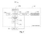
- FIG. 3is another functional module diagram of the battery shown in FIG. 1 .
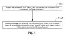
- FIG. 4is a schematic flow chart of a battery control method according to an embodiment of the present disclosure.
- FIG. 1schematically shows an example battery 100 consistent with embodiments of the present disclosure.
- the battery 100includes a housing 11 , a battery core 13 , and a control circuit 17 .
- the battery core 13 and the control circuit 17are both disposed in the housing 11 .
- the control circuit 17includes a switch 171 , and the switch 171 is electrically connected to the battery core 13 .
- the battery 100by controlling on and off of the switch 171 , causes the battery core 13 and the control circuit 17 to establish an electrical connection therebetween or to be disconnected from each other, and hence causes the battery core 13 , through the switch 171 , to provide a power supply for the control circuit 17 or cut off power supply for the control circuit 17 .
- the switch 171may include a Metal Oxide Semiconductor Field Effect Transistor (MOS transistor), or may include another electronic switch such as a relay or a mechanical switch. In some embodiments, the switch 171 includes a MOS transistor.
- MOS transistorMetal Oxide Semiconductor Field Effect Transistor
- the control circuit 17may include one or more circuit boards, or include one or more microprocessors.
- FIG. 2is a block diagram showing the battery core 13 and the control circuit 17 of the battery 100 according to an embodiment of the disclosure. As shown in FIG. 2 , the control circuit 17 further includes a power input terminal 172 , a control unit 173 , a Ferromagnetic Random Access Memory (FRAM) 174 , and a trigger key S. Both the control unit 173 and the FRAM 174 are electrically connected to the power input terminal 172 .
- FRAMFerromagnetic Random Access Memory
- the power input terminal 172is electrically connected to an anode and/or a cathode of the battery core 13 through the switch 171 to receive electric energy output by the battery core 13 , and then can serve as a power supply of the control circuit 17 to supply power for operation of the control unit 173 and the FRAM 174 .
- the control unit 173may include a Field-Programmable Gate Array (FPGA), a Micro-Controller Unit (MCU) with a control program embedded therein, a single chip microcomputer, or the like. In some embodiments, the control unit 173 includes an MCU.
- FPGAField-Programmable Gate Array
- MCUMicro-Controller Unit
- the FRAM 174is electrically connected to the control unit 173 and used to store state information of the battery and factory information such as model of the battery core, chemical properties of the battery core, production date of the battery, serial number of the battery, and manufacturer of the battery.
- the state information of the battery core 13at least can include a present capacity of the battery core 13 , a present voltage of the battery core 13 , a present current of the battery core 13 , a present battery temperature of the battery core 13 , and/or other parameters.
- the FRAM 174has advantages of a fast read and write speed and non-volatility, and can allow the battery to rapidly save the present state when shutting down and to rapidly restore the state prior to the last power-off.
- the FRAM 174may switch between a dynamic mode and a non-volatile mode.
- the FRAM 174can have a high dielectric constant because of its special memory structure, and can be used as an ordinary Dynamic Random Access Memory (DRAM).
- DRAMDynamic Random Access Memory
- the FRAM 174due to a stable state resulting from polarization, can effectively store data even without power. That is, even if the switch 171 is disconnected to stop the battery core 13 from supplying power to the control circuit 17 , the FRAM 174 can still effectively operate and has a non-volatile characteristic.
- the switch 171 between the battery core 13 and the control circuit 17when the switch 171 between the battery core 13 and the control circuit 17 is switched on to cause the battery core 13 to be electrically connected with the control circuit 17 , the battery core 13 provides a power supply to the control circuit 17 .
- the FRAM 174operates in the dynamic mode.
- the control unit 173may perform a read/write operation on the FRAM 174 .
- the state information of the battery core 13can be stored to the FRAM 174 .
- the switch 171 between the battery core 13 and the control circuit 17is switched off to disconnect the battery core 13 from the control circuit 17 , the battery core 13 can stop supplying power to the control circuit 17 , and the FRAM 174 switches to the non-volatile mode. At this point, the FRAM 174 can still effectively keep the data stored to the FRAM 174 by the control unit 173 to prevent loss of the data.
- the trigger key Sis configured to control the battery core 13 to power on or power off. For example, when the battery core 13 is in a power-on state, that is, the battery core 13 is supplying power to an external load, if a user presses down the trigger key S, the battery core 13 can switch to a power-off state. When the battery core 13 is in a power-off state, that is, the battery core 13 is not supplying power to an external load, if the user presses down the trigger key S, the battery core 13 will switch to the power-on state. That is, the battery core 13 restores power supply to an external load. Furthermore, the trigger key S is electrically connected with the control unit 173 . The trigger key S is used to send a trigger signal to the control unit 173 , and the control unit 173 controls on and off of the switch 171 in accordance with the trigger signal.
- the control circuit 17further includes a key power supply Vcc.
- the trigger key Sis electrically connected with the key power supply Vcc.
- the key power supply Vcccan temporarily supply power to the control unit 173 through the trigger key S.
- the control unit 173can store the present state information to the FRAM 174 , and control the switch 171 to switch off to disconnect the battery core 13 from the control circuit 17 . That is, the battery core 13 can cut off the power supply to the control circuit 17 to reduce the power consumption of the control circuit 17 to zero, thereby effectively extending storage life of the battery 100 .
- the key power supply Vcccan temporarily supply power to the control unit 173 through the trigger key S.
- the control unit 173can control the switch 171 to switch on, so as to establish an electrical connection between the battery core 13 and the control circuit 17 to allow the battery core 13 to continue to supply power for the control circuit 17 .
- the FRAM 174can switch to the dynamic mode again to allow the control unit 173 to perform the read/write operation on the FRAM 174 . That is, the control circuit 17 can resume normal operation, and continue to operate in accordance with the state before last shutdown.
- the key power supply Vccmay be omitted and the trigger key S can be directly electrically connected to the battery core 13 .
- the battery core 13may temporarily supply power to the control unit 173 directly through the trigger key S.
- the control circuit 17further includes a charge and discharge protection circuit 175 and a charge and discharge connecting terminal 176 .
- the charge and discharge protection circuit 175is electrically connected to the control unit 173 .
- the battery core 13may be charged or supply power to an external load through the charge and discharge protection circuit 175 .
- the charge and discharge connecting terminal 176is electrically connected to the charge and discharge protection circuit 175 .
- the charge and discharge connecting terminal 176can be electrically connected with an external device (not shown) and hence can server as a charge and discharge interface of the battery 100 . For example, when the battery core 13 is electrically connected to the external device through the charge and discharge connecting terminal 176 , the external device can charge the battery 100 through the charge and discharge connecting terminal 176 .
- the control circuit 17further includes a power supply switch SW.
- the power supply switch SWis electrically connected between the charge and discharge protection circuit 175 and the battery core 13 , and is electrically connected with the control unit 173 .
- the control unit 173can control the electrical connection between the battery core 13 and the charge and discharge protection circuit 175 through the power supply switch SW, and further control of the electrical connection between the battery core 13 and the external device through the charge and discharge protection circuit 175 .
- the power supply switch SWcan be omitted from the control circuit 17 .
- the charge and discharge protection circuit 175can be electrically connected with the battery core 13 through the switch 171 .
- the control unit 173can control of the electrical connection between the battery core 13 and the charge and discharge protection circuit 175 through the switch 171 , and further control the electrical connection between the battery core 13 and the external device through the charge and discharge protection circuit 175 .
- the charge and discharge protection circuit 175has a switch function, the charge and discharge protection circuit 175 can be electrically connect with the control unit 173 and the battery core 13 directly.
- control unit 173can control the electrical connection between the battery core 13 and the charge and discharge protection circuit 175 through on and off of the charge and discharge protection circuit 175 , and further control the electrical connection between the battery core 13 and the external device through the charge and discharge protection circuit 175 .
- control circuit 17further includes a signal interface 178 .
- the signal interface 178is electrically connected with the control unit 173 and can be configured to establish an electrical connection between the control circuit 17 and another external apparatus, for example, an unmanned aerial vehicle, so as to enable the external apparatus to conduct data communication with the control circuit 17 .
- the control circuit 17can operate normally.
- the FRAM 174 of the control circuit 17can operate in the dynamic mode, and the control unit 173 can acquire the state information of the battery core 13 periodically or in real time and write the acquired state information into the FRAM 174 .
- the battery core 13can switch to the power-off state.
- the battery core 13 or the key power supply Vcccan temporarily supply power to the control unit 173 through the trigger key S, and the control unit 173 can acquire the state information of the battery core 13 and store the state information to the FRAM 174 .
- the control unit 173can switch off the switch 171 to disconnect the battery core 13 from the control circuit 17 .
- the battery core 13can cut off the power supply of the control circuit 17 .
- the control circuit 17can stop operating to reduce the power consumption thereof to zero, thereby effectively extending storage life of the battery 100 .
- the FRAM 174can switch to the non-volatile mode. Therefore, even if the battery core 13 is disconnected from the control circuit 17 , the FRAM 174 can still effectively keep the state information of the battery core 13 to prevent loss of the data.
- control unit 173includes a mechanical switch. If the user presses down the mechanical switch, the battery core 13 can switch to the power-off state, and the FRAM 174 can save the state information of the battery core 13 prior to the power-off.
- the battery core 13When the battery core 13 is in the power-off state and the user presses down the trigger key S again, the battery core 13 can switch to the power-on state. At this point, the battery core 13 or the key power supply Vcc can temporarily supply power to the control unit 173 through the trigger key S.
- the control unit 173can control the switch 171 to switch on, and then an electrical connection between the battery core 13 and the control circuit 17 can be established to allow the battery core 13 to continue to supply power for the control circuit 17 .
- the FRAM 174can switch to the dynamic mode again to facilitate the control unit 173 to perform the read/write operation on the FRAM 174 . In this way, the control circuit 17 can continue to operate in accordance with the state before the last shutdown.
- FIG. 3is a block diagram showing the battery core 13 and the control circuit 17 according to another embodiment of the disclosure.
- the control circuit 17further includes a sensing circuit 179 .
- the charge and discharge connecting terminal 176is electrically connected with the battery core 13 through the sensing circuit 179 .
- the sensing circuit 178is further electrically connected with the control unit 173 and used to sense whether the charge and discharge connecting terminal 176 is in electrical communication with an external device. If the sensing circuit 178 senses that the charge and discharge connecting terminal 176 is in electrical communication with the external device, the control unit 173 controls the switch 171 to switch on. When the sensing circuit 178 senses that the charge and discharge connecting terminal 176 is not in electrical communication with the external device, the control unit 173 controls the switch 171 to switch off.
- FIG. 4a schematic flow chart of a battery control method according to an embodiment of the present disclosure.
- the methodcan be implemented in control unit, such as the control unit 173 shown in FIG. 2 or 3 .
- the state information of the battery core 13is acquired, and the state information is stored into the FRAM 174 .
- the state informationincludes at least one of the followings: a capacity of the battery core 13 , a voltage of the battery core 13 , a current of the battery core 13 , or a battery temperature of the battery core 13 .
- power supply from the battery core 13 to the FRAM 174is controlled, to control the FRAM 174 to switch to the dynamic mode or the non-volatile mode to update or read the state information.
- the battery 100further includes the switch 171 .
- the switch 171is electrically connected with the battery core 13 and the FRAM 174 .
- the control unit 173by switching on or switching off the switch 171 , can establish or disconnect the electrical connection between the FRAM 174 and the battery core 13 .
- the battery core 13has a power-on state and a power-off state.
- the control unit 173can store the state information to the FRAM 174 .
- the control unit 173may acquire the state information from the FRAM 174 .
- the battery 100further includes the trigger key S.
- the trigger key Sis configured to control on or off of the battery core 13 .
- the battery core 13when the battery core 13 is in the power-on state, that is, the battery core 13 is supplying power to an external load, if a user presses down the trigger key S, the battery core 13 switches to the power-off state.
- the battery core 13When the battery core 13 is in the power-off state, that is, the battery core 13 is not supplying power to an external load, if the user presses down the trigger key S again, the battery core 13 will switch to the power-on state. That is, the battery core 13 restores the power supply to an external load.
- the trigger key Sis electrically connected with the control unit 173 .
- the trigger key Sis configured to send a trigger signal to the control unit 173 , and the control unit 173 controls the on and off of the switch 171 in accordance with the trigger signal.
- the trigger key Smay be electrically connected to the battery core 13 . Therefore, when the trigger key S is triggered, the battery core 13 can temporarily supply power to the control unit 173 directly through the trigger key S.
- the battery 100further includes the key power supply Vcc electrically connected with the trigger key S.
- the key power supply Vcccan temporarily supply power to the control unit 173 through the trigger key S.
- control circuit 17further includes the charge and discharge connecting terminal 176 .
- the control unit 173can control the electrical connection between the FRAM 174 and the battery core 13 in accordance with the electrical connection between the charge and discharge connecting terminal 176 and the external device.
- the aforementioned battery 100may cut off the power supply of the control circuit 17 to reduce power consumption of the control circuit 17 to zero.
- the problem of overdischarge of the battery core 13can be avoided, and storage time of the battery 100 can be effectively extended.
- the control circuit 17includes the FRAM 174 . Therefore, even if the battery core 13 is in a power-off state, the FRAM 174 can still effectively hold data to prevent information loss. That is, the control circuit 17 and the battery 100 having the control circuit 17 can effectively reduce power consumption, and can also effectively hold data to prevent information loss.
Landscapes
- Engineering & Computer Science (AREA)
- Chemical & Material Sciences (AREA)
- Chemical Kinetics & Catalysis (AREA)
- Electrochemistry (AREA)
- General Chemical & Material Sciences (AREA)
- Manufacturing & Machinery (AREA)
- Microelectronics & Electronic Packaging (AREA)
- Power Engineering (AREA)
- Charge And Discharge Circuits For Batteries Or The Like (AREA)
- Secondary Cells (AREA)
Abstract
Description
- This is a continuation application of International Application No. PCT/CN2015/082608, filed on Jun. 29, 2015, the entire contents of which are incorporated herein by reference.
- The present disclosure relates to a control circuit, a battery having the control circuit and a battery control method.
- A conventional battery on the market usually includes a control circuit coupled to a battery core to implement many circuit functions such as limiting the minimum discharging voltage and the maximum charging voltage, and detecting the temperature and current of the battery core. However, when the battery core does not supply power to an external load, the control circuit is still in an operating state. For example, a control unit in the control circuit needs to monitor state information of the battery core regularly and store the state information to a register. When the battery core does not supply power to an external load, the control circuit may still consume power, and at this point, the battery is still in a power consumption state.
- At present, a common solution is as follows: when the battery is in a power-off state, the control unit detects a voltage of the battery core, and, when the voltage of the battery core is lower than a preset value, sends a corresponding control instruction to cause the battery to enter into a low power consumption state. However, even if the battery enters into the low power consumption state, the battery core still needs to provide a corresponding power supply to maintain a state of the register inside the battery. That is, the battery core cannot completely cut off the power supply of the control circuit, and thus cannot completely eliminate loss of electricity.
- In accordance with the disclosure, there is provided a control circuit for controlling a battery core. The control circuit includes a power input terminal electrically connected to the battery core, a ferromagnetic random access memory having a dynamic mode and a non-volatile mode, and a control unit electrically connected with the ferromagnetic random access memory and the power input terminal. The control unit is configured to acquire state information of the battery core and store the state information to the ferromagnetic random access memory, and switch on or off an electrical connection between the power input terminal and the battery core to switch the ferromagnetic random access memory to the dynamic mode or the non-volatile mode.
- Also in accordance with the disclosure, there is provided a battery including a battery core and a control circuit for controlling the battery core. The control circuit includes a power input terminal electrically connected to the battery core, a ferromagnetic random access memory having a dynamic mode and a non-volatile mode, and a control unit electrically connected with the ferromagnetic random access memory and the power input terminal. The control unit is configured to acquire state information of the battery core and store the state information to the ferromagnetic random access memory, and switch on or off an electrical connection between the power input terminal and the battery core to switch the ferromagnetic random access memory to the dynamic mode or the non-volatile mode.
FIG. 1 is a schematic structural diagram of a battery according to an embodiment of the present disclosure.FIG. 2 is one functional module diagram of the battery shown inFIG. 1 .FIG. 3 is another functional module diagram of the battery shown inFIG. 1 .FIG. 4 is a schematic flow chart of a battery control method according to an embodiment of the present disclosure.- Technical solutions of the present disclosure will be described with reference to the drawings. It will be appreciated that embodiments as described in the disclosure are some rather than all of the embodiments of the present disclosure. Other embodiments, which are conceived by those having ordinary skills in the art on the basis of the disclosed embodiments without inventive efforts, should fall within the scope of the present disclosure.
FIG. 1 schematically shows anexample battery 100 consistent with embodiments of the present disclosure. As shown inFIG. 1 , thebattery 100 includes ahousing 11, abattery core 13, and acontrol circuit 17. Thebattery core 13 and thecontrol circuit 17 are both disposed in thehousing 11. Thecontrol circuit 17 includes aswitch 171, and theswitch 171 is electrically connected to thebattery core 13. Thebattery 100, by controlling on and off of theswitch 171, causes thebattery core 13 and thecontrol circuit 17 to establish an electrical connection therebetween or to be disconnected from each other, and hence causes thebattery core 13, through theswitch 171, to provide a power supply for thecontrol circuit 17 or cut off power supply for thecontrol circuit 17.- The
switch 171 may include a Metal Oxide Semiconductor Field Effect Transistor (MOS transistor), or may include another electronic switch such as a relay or a mechanical switch. In some embodiments, theswitch 171 includes a MOS transistor. - The
control circuit 17 may include one or more circuit boards, or include one or more microprocessors.FIG. 2 is a block diagram showing thebattery core 13 and thecontrol circuit 17 of thebattery 100 according to an embodiment of the disclosure. As shown inFIG. 2 , thecontrol circuit 17 further includes apower input terminal 172, acontrol unit 173, a Ferromagnetic Random Access Memory (FRAM)174, and a trigger key S. Both thecontrol unit 173 and theFRAM 174 are electrically connected to thepower input terminal 172. - The
power input terminal 172 is electrically connected to an anode and/or a cathode of thebattery core 13 through theswitch 171 to receive electric energy output by thebattery core 13, and then can serve as a power supply of thecontrol circuit 17 to supply power for operation of thecontrol unit 173 and theFRAM 174. - The
control unit 173 may include a Field-Programmable Gate Array (FPGA), a Micro-Controller Unit (MCU) with a control program embedded therein, a single chip microcomputer, or the like. In some embodiments, thecontrol unit 173 includes an MCU. - The FRAM174 is electrically connected to the
control unit 173 and used to store state information of the battery and factory information such as model of the battery core, chemical properties of the battery core, production date of the battery, serial number of the battery, and manufacturer of the battery. The state information of thebattery core 13 at least can include a present capacity of thebattery core 13, a present voltage of thebattery core 13, a present current of thebattery core 13, a present battery temperature of thebattery core 13, and/or other parameters. TheFRAM 174 has advantages of a fast read and write speed and non-volatility, and can allow the battery to rapidly save the present state when shutting down and to rapidly restore the state prior to the last power-off. - In some embodiments, the
FRAM 174 may switch between a dynamic mode and a non-volatile mode. When operating in the dynamic mode, theFRAM 174 can have a high dielectric constant because of its special memory structure, and can be used as an ordinary Dynamic Random Access Memory (DRAM). When operating in the non-volatile mode, theFRAM 174, due to a stable state resulting from polarization, can effectively store data even without power. That is, even if theswitch 171 is disconnected to stop thebattery core 13 from supplying power to thecontrol circuit 17, theFRAM 174 can still effectively operate and has a non-volatile characteristic. - Further, when the
switch 171 between thebattery core 13 and thecontrol circuit 17 is switched on to cause thebattery core 13 to be electrically connected with thecontrol circuit 17, thebattery core 13 provides a power supply to thecontrol circuit 17. At this point, the FRAM174 operates in the dynamic mode. Thecontrol unit 173 may perform a read/write operation on theFRAM 174. For example, the state information of thebattery core 13 can be stored to theFRAM 174. When theswitch 171 between thebattery core 13 and thecontrol circuit 17 is switched off to disconnect thebattery core 13 from thecontrol circuit 17, thebattery core 13 can stop supplying power to thecontrol circuit 17, and theFRAM 174 switches to the non-volatile mode. At this point, theFRAM 174 can still effectively keep the data stored to theFRAM 174 by thecontrol unit 173 to prevent loss of the data. - The trigger key S is configured to control the
battery core 13 to power on or power off. For example, when thebattery core 13 is in a power-on state, that is, thebattery core 13 is supplying power to an external load, if a user presses down the trigger key S, thebattery core 13 can switch to a power-off state. When thebattery core 13 is in a power-off state, that is, thebattery core 13 is not supplying power to an external load, if the user presses down the trigger key S, thebattery core 13 will switch to the power-on state. That is, thebattery core 13 restores power supply to an external load. Furthermore, the trigger key S is electrically connected with thecontrol unit 173. The trigger key S is used to send a trigger signal to thecontrol unit 173, and thecontrol unit 173 controls on and off of theswitch 171 in accordance with the trigger signal. - In some embodiments, the
control circuit 17 further includes a key power supply Vcc. The trigger key S is electrically connected with the key power supply Vcc. When the trigger key S controls thebattery core 13 to switch to the power-off state, the key power supply Vcc can temporarily supply power to thecontrol unit 173 through the trigger key S. At this point, thecontrol unit 173 can store the present state information to theFRAM 174, and control theswitch 171 to switch off to disconnect thebattery core 13 from thecontrol circuit 17. That is, thebattery core 13 can cut off the power supply to thecontrol circuit 17 to reduce the power consumption of thecontrol circuit 17 to zero, thereby effectively extending storage life of thebattery 100. When thebattery core 13 is controlled, through the trigger key S, to switch to the on state, the key power supply Vcc can temporarily supply power to thecontrol unit 173 through the trigger key S. At this point, thecontrol unit 173 can control theswitch 171 to switch on, so as to establish an electrical connection between thebattery core 13 and thecontrol circuit 17 to allow thebattery core 13 to continue to supply power for thecontrol circuit 17. At the same time, theFRAM 174 can switch to the dynamic mode again to allow thecontrol unit 173 to perform the read/write operation on theFRAM 174. That is, thecontrol circuit 17 can resume normal operation, and continue to operate in accordance with the state before last shutdown. - It can be understood that, in some other embodiments, the key power supply Vcc may be omitted and the trigger key S can be directly electrically connected to the
battery core 13. In these embodiments, when the trigger key S is triggered, thebattery core 13 may temporarily supply power to thecontrol unit 173 directly through the trigger key S. - As shown in
FIG. 2 , thecontrol circuit 17 further includes a charge anddischarge protection circuit 175 and a charge and discharge connectingterminal 176. The charge anddischarge protection circuit 175 is electrically connected to thecontrol unit 173. Thebattery core 13 may be charged or supply power to an external load through the charge anddischarge protection circuit 175. The charge and discharge connectingterminal 176 is electrically connected to the charge anddischarge protection circuit 175. The charge and discharge connecting terminal176 can be electrically connected with an external device (not shown) and hence can server as a charge and discharge interface of thebattery 100. For example, when thebattery core 13 is electrically connected to the external device through the charge and discharge connectingterminal 176, the external device can charge thebattery 100 through the charge and discharge connectingterminal 176. - In some embodiments, as shown in
FIG. 2 , thecontrol circuit 17 further includes a power supply switch SW. The power supply switch SW is electrically connected between the charge anddischarge protection circuit 175 and thebattery core 13, and is electrically connected with thecontrol unit 173. Thecontrol unit 173 can control the electrical connection between thebattery core 13 and the charge anddischarge protection circuit 175 through the power supply switch SW, and further control of the electrical connection between thebattery core 13 and the external device through the charge anddischarge protection circuit 175. - In some other embodiments, the power supply switch SW can be omitted from the
control circuit 17. Instead, the charge anddischarge protection circuit 175 can be electrically connected with thebattery core 13 through theswitch 171. In these embodiments, thecontrol unit 173 can control of the electrical connection between thebattery core 13 and the charge anddischarge protection circuit 175 through theswitch 171, and further control the electrical connection between thebattery core 13 and the external device through the charge anddischarge protection circuit 175. In some other embodiments, if the charge anddischarge protection circuit 175 has a switch function, the charge anddischarge protection circuit 175 can be electrically connect with thecontrol unit 173 and thebattery core 13 directly. In these embodiments, thecontrol unit 173 can control the electrical connection between thebattery core 13 and the charge anddischarge protection circuit 175 through on and off of the charge anddischarge protection circuit 175, and further control the electrical connection between thebattery core 13 and the external device through the charge anddischarge protection circuit 175. - In some embodiments, as shown in
FIG. 2 , thecontrol circuit 17 further includes asignal interface 178. Thesignal interface 178 is electrically connected with thecontrol unit 173 and can be configured to establish an electrical connection between thecontrol circuit 17 and another external apparatus, for example, an unmanned aerial vehicle, so as to enable the external apparatus to conduct data communication with thecontrol circuit 17. - When the
battery core 13 is in the power-on state, thecontrol circuit 17 can operate normally. At this point, theFRAM 174 of thecontrol circuit 17 can operate in the dynamic mode, and thecontrol unit 173 can acquire the state information of thebattery core 13 periodically or in real time and write the acquired state information into theFRAM 174. If the user presses down the trigger key S, thebattery core 13 can switch to the power-off state. At this point, thebattery core 13 or the key power supply Vcc can temporarily supply power to thecontrol unit 173 through the trigger key S, and thecontrol unit 173 can acquire the state information of thebattery core 13 and store the state information to theFRAM 174. Next, thecontrol unit 173 can switch off theswitch 171 to disconnect thebattery core 13 from thecontrol circuit 17. That is, thebattery core 13 can cut off the power supply of thecontrol circuit 17. At this point, thecontrol circuit 17 can stop operating to reduce the power consumption thereof to zero, thereby effectively extending storage life of thebattery 100. In addition, when thebattery core 13 cuts off the power supply of thecontrol circuit 17, theFRAM 174 can switch to the non-volatile mode. Therefore, even if thebattery core 13 is disconnected from thecontrol circuit 17, theFRAM 174 can still effectively keep the state information of thebattery core 13 to prevent loss of the data. - In some other embodiments, the
control unit 173 includes a mechanical switch. If the user presses down the mechanical switch, thebattery core 13 can switch to the power-off state, and theFRAM 174 can save the state information of thebattery core 13 prior to the power-off. - When the
battery core 13 is in the power-off state and the user presses down the trigger key S again, thebattery core 13 can switch to the power-on state. At this point, thebattery core 13 or the key power supply Vcc can temporarily supply power to thecontrol unit 173 through the trigger key S. Thecontrol unit 173 can control theswitch 171 to switch on, and then an electrical connection between thebattery core 13 and thecontrol circuit 17 can be established to allow thebattery core 13 to continue to supply power for thecontrol circuit 17. At the same time, theFRAM 174 can switch to the dynamic mode again to facilitate thecontrol unit 173 to perform the read/write operation on theFRAM 174. In this way, thecontrol circuit 17 can continue to operate in accordance with the state before the last shutdown. FIG. 3 is a block diagram showing thebattery core 13 and thecontrol circuit 17 according to another embodiment of the disclosure. In the example shown inFIG. 3 , the trigger key S is omitted. In these embodiments, as shown inFIG. 3 , thecontrol circuit 17 further includes asensing circuit 179. The charge and discharge connectingterminal 176 is electrically connected with thebattery core 13 through thesensing circuit 179. Thesensing circuit 178 is further electrically connected with thecontrol unit 173 and used to sense whether the charge and discharge connectingterminal 176 is in electrical communication with an external device. If thesensing circuit 178 senses that the charge and discharge connectingterminal 176 is in electrical communication with the external device, thecontrol unit 173 controls theswitch 171 to switch on. When thesensing circuit 178 senses that the charge and discharge connectingterminal 176 is not in electrical communication with the external device, thecontrol unit 173 controls theswitch 171 to switch off.FIG. 4 a schematic flow chart of a battery control method according to an embodiment of the present disclosure. The method can be implemented in control unit, such as thecontrol unit 173 shown inFIG. 2 or 3 .- As shown in
FIG. 4 , at S101, the state information of thebattery core 13 is acquired, and the state information is stored into theFRAM 174. - The state information includes at least one of the followings: a capacity of the
battery core 13, a voltage of thebattery core 13, a current of thebattery core 13, or a battery temperature of thebattery core 13. - At S102, power supply from the
battery core 13 to theFRAM 174 is controlled, to control theFRAM 174 to switch to the dynamic mode or the non-volatile mode to update or read the state information. - As described above, the
battery 100 further includes theswitch 171. Theswitch 171 is electrically connected with thebattery core 13 and theFRAM 174. Thecontrol unit 173, by switching on or switching off theswitch 171, can establish or disconnect the electrical connection between theFRAM 174 and thebattery core 13. - As described above, the
battery core 13 has a power-on state and a power-off state. When thebattery core 13 is switched to the power-off state, thecontrol unit 173 can store the state information to theFRAM 174. When thebattery core 13 switches to the power-on state, thecontrol unit 173 may acquire the state information from theFRAM 174. - As described above, the
battery 100 further includes the trigger key S. The trigger key S is configured to control on or off of thebattery core 13. For example, when thebattery core 13 is in the power-on state, that is, thebattery core 13 is supplying power to an external load, if a user presses down the trigger key S, thebattery core 13 switches to the power-off state. When thebattery core 13 is in the power-off state, that is, thebattery core 13 is not supplying power to an external load, if the user presses down the trigger key S again, thebattery core 13 will switch to the power-on state. That is, thebattery core 13 restores the power supply to an external load. - In some embodiments, the trigger key S is electrically connected with the
control unit 173. The trigger key S is configured to send a trigger signal to thecontrol unit 173, and thecontrol unit 173 controls the on and off of theswitch 171 in accordance with the trigger signal. - In some embodiments, the trigger key S may be electrically connected to the
battery core 13. Therefore, when the trigger key S is triggered, thebattery core 13 can temporarily supply power to thecontrol unit 173 directly through the trigger key S. - In some embodiments, the
battery 100 further includes the key power supply Vcc electrically connected with the trigger key S. The key power supply Vcc can temporarily supply power to thecontrol unit 173 through the trigger key S. - In some embodiments, the
control circuit 17 further includes the charge and discharge connectingterminal 176. Thecontrol unit 173 can control the electrical connection between theFRAM 174 and thebattery core 13 in accordance with the electrical connection between the charge and discharge connectingterminal 176 and the external device. - The
aforementioned battery 100 may cut off the power supply of thecontrol circuit 17 to reduce power consumption of thecontrol circuit 17 to zero. The problem of overdischarge of thebattery core 13 can be avoided, and storage time of thebattery 100 can be effectively extended. At the same time, thecontrol circuit 17 includes theFRAM 174. Therefore, even if thebattery core 13 is in a power-off state, theFRAM 174 can still effectively hold data to prevent information loss. That is, thecontrol circuit 17 and thebattery 100 having thecontrol circuit 17 can effectively reduce power consumption, and can also effectively hold data to prevent information loss. - The foregoing are merely some embodiments of the disclosure but are not intended to limit the scope of the disclosure. Any equivalent modifications to a structure or process flow, which are made without departing from the specification and the drawings of the disclosure, and a direct or indirect application in other relevant technical fields, shall also fall into the scope of the disclosure.
Claims (20)
Applications Claiming Priority (1)
| Application Number | Priority Date | Filing Date | Title |
|---|---|---|---|
| PCT/CN2015/082608WO2017000103A1 (en) | 2015-06-29 | 2015-06-29 | Control circuit, battery provided with control circuit and battery control method |
Related Parent Applications (1)
| Application Number | Title | Priority Date | Filing Date |
|---|---|---|---|
| PCT/CN2015/082608ContinuationWO2017000103A1 (en) | 2015-06-29 | 2015-06-29 | Control circuit, battery provided with control circuit and battery control method |
Publications (2)
| Publication Number | Publication Date |
|---|---|
| US20180123183A1true US20180123183A1 (en) | 2018-05-03 |
| US11139511B2 US11139511B2 (en) | 2021-10-05 |
Family
ID=55888361
Family Applications (1)
| Application Number | Title | Priority Date | Filing Date |
|---|---|---|---|
| US15/858,743Active2036-06-23US11139511B2 (en) | 2015-06-29 | 2017-12-29 | Control circuit, battery having the control circuit and battery control method |
Country Status (5)
| Country | Link |
|---|---|
| US (1) | US11139511B2 (en) |
| EP (1) | EP3316383A4 (en) |
| JP (1) | JP6379203B2 (en) |
| CN (2) | CN105580242B (en) |
| WO (1) | WO2017000103A1 (en) |
Cited By (3)
| Publication number | Priority date | Publication date | Assignee | Title |
|---|---|---|---|---|
| US10587128B2 (en)* | 2015-06-30 | 2020-03-10 | SZ DJI Technology Co., Ltd. | Charging control circuit, charging device, charging system and charging control method |
| CN114735126A (en)* | 2021-03-18 | 2022-07-12 | 浙江铅锂智行科技有限公司 | an electric vehicle |
| CN115642661A (en)* | 2021-07-19 | 2023-01-24 | 广达电脑股份有限公司 | Intelligent battery device and electronic device thereof |
Families Citing this family (4)
| Publication number | Priority date | Publication date | Assignee | Title |
|---|---|---|---|---|
| CN106716161B (en)* | 2016-10-28 | 2020-08-04 | 深圳市大疆创新科技有限公司 | Battery control method and system and battery |
| JP6916639B2 (en)* | 2017-03-13 | 2021-08-11 | エイブリック株式会社 | Charge / discharge control circuit and battery device |
| CN107732340B (en)* | 2017-10-27 | 2019-11-08 | 宁波三星医疗电气股份有限公司 | A kind of clock restorative procedure based on intelligent power terminal clock battery undervoltage |
| EP3761473A4 (en)* | 2018-02-28 | 2021-10-13 | SZ DJI Technology Co., Ltd. | Battery control circuit, power supply control system, and movable platform |
Citations (5)
| Publication number | Priority date | Publication date | Assignee | Title |
|---|---|---|---|---|
| US5710931A (en)* | 1994-09-07 | 1998-01-20 | Canon Kabushiki Kaisha | Suspension state control for information processing devices such as battery powered computers |
| US6228519B1 (en)* | 1997-10-06 | 2001-05-08 | Reveo, Inc. | Metal-air fuel cell battery systems having mechanism for extending the path length of metal-fuel tape during discharging and recharging modes of operation |
| CN1441510A (en)* | 2002-02-27 | 2003-09-10 | 合邦电子股份有限公司 | Intelligent secondary battery management method and device |
| US20090185441A1 (en)* | 2008-01-18 | 2009-07-23 | Andreas Kux | Integrated Circuit and Method to Operate an Integrated Circuit |
| US20130049703A1 (en)* | 2011-08-31 | 2013-02-28 | GM Global Technology Operations LLC | Systems and methods for providing power to a load based upon a control strategy |
Family Cites Families (27)
| Publication number | Priority date | Publication date | Assignee | Title |
|---|---|---|---|---|
| US3858184A (en)* | 1973-01-22 | 1974-12-31 | Monolithic Syst Corp | Automatic non-interrupting refresh technique |
| AU559311B2 (en)* | 1984-02-15 | 1987-03-05 | Matsushita Electric Industrial Co., Ltd. | Pay tv charge/time data display |
| JPH0681425B2 (en)* | 1990-03-31 | 1994-10-12 | アントン/バウエル インコーポレーテッド | Battery system method and device and battery pack |
| JPH06302179A (en)* | 1993-04-13 | 1994-10-28 | Casio Comput Co Ltd | Electronic equipment |
| KR970010634B1 (en)* | 1994-10-25 | 1997-06-28 | 삼성전자 주식회사 | Network hibernation system |
| KR0172003B1 (en)* | 1995-03-28 | 1999-03-30 | 김광호 | Computer system and its control method |
| JP4013003B2 (en)* | 1998-03-27 | 2007-11-28 | 宇部興産株式会社 | battery pack |
| JP3366568B2 (en)* | 1998-03-31 | 2003-01-14 | 宮田工業株式会社 | Battery charger |
| JP2001155781A (en)* | 1999-11-24 | 2001-06-08 | Toshiba Battery Co Ltd | Secondary battery device |
| CN1307260A (en)* | 2000-01-25 | 2001-08-08 | 睿阳科技股份有限公司 | Uninterruptible power supply device and method capable of automatically storing data |
| JP3638109B2 (en)* | 2000-02-07 | 2005-04-13 | Necトーキン栃木株式会社 | Battery pack |
| JP2003180038A (en)* | 2001-12-11 | 2003-06-27 | Rohm Co Ltd | Charge control device |
| DE10206485B4 (en)* | 2002-02-16 | 2007-06-21 | Robert Bosch Gmbh | Power supply and electrical appliance |
| JP2006260981A (en)* | 2005-03-17 | 2006-09-28 | Shin Kobe Electric Mach Co Ltd | Battery controller |
| CN200979994Y (en)* | 2006-06-30 | 2007-11-21 | 宁波力达物料搬运设备厂 | A storage battery charger |
| JP4973112B2 (en)* | 2006-10-06 | 2012-07-11 | パナソニック株式会社 | A system comprising a charging device and a storage battery state detection device |
| JP2009063502A (en)* | 2007-09-07 | 2009-03-26 | Seiko Epson Corp | Battery remaining capacity management system and control method thereof |
| JP2011182592A (en)* | 2010-03-02 | 2011-09-15 | Sanyo Electric Co Ltd | Battery pack |
| JP2011188570A (en)* | 2010-03-05 | 2011-09-22 | Toyota Motor Corp | Apparatus and method for power supply control |
| CN102447277A (en)* | 2010-10-14 | 2012-05-09 | 和映科技有限公司 | Battery module and method for recording battery module signal |
| CN201821142U (en)* | 2010-10-21 | 2011-05-04 | 艾利和电子科技(中国)有限公司 | Portable Electronics Power Supply System |
| JP2012168728A (en)* | 2011-02-14 | 2012-09-06 | Mitsumi Electric Co Ltd | Protection module and state information management method in protection module |
| JP2012221854A (en)* | 2011-04-12 | 2012-11-12 | Sanyo Electric Co Ltd | Battery pack with output connector |
| US9883603B2 (en)* | 2013-07-16 | 2018-01-30 | Texas Instruments Incorporated | Electronic pull tab for battery protection |
| CN103701163B (en)* | 2013-12-06 | 2018-05-01 | 深圳市大疆创新科技有限公司 | Battery, aircraft with battery and battery control method |
| US10491014B2 (en)* | 2014-07-15 | 2019-11-26 | Dell Products, L.P. | Battery management system and method for extending time until a battery reaches an over-discharged state during storage of an information handling system |
| CN204696765U (en)* | 2015-06-29 | 2015-10-07 | 深圳市大疆创新科技有限公司 | Battery |
- 2015
- 2015-06-29JPJP2016543196Apatent/JP6379203B2/ennot_activeExpired - Fee Related
- 2015-06-29EPEP15896634.1Apatent/EP3316383A4/ennot_activeWithdrawn
- 2015-06-29CNCN201580001653.4Apatent/CN105580242B/enactiveActive
- 2015-06-29CNCN201711072206.5Apatent/CN107769317B/enactiveActive
- 2015-06-29WOPCT/CN2015/082608patent/WO2017000103A1/ennot_activeCeased
- 2017
- 2017-12-29USUS15/858,743patent/US11139511B2/enactiveActive
Patent Citations (5)
| Publication number | Priority date | Publication date | Assignee | Title |
|---|---|---|---|---|
| US5710931A (en)* | 1994-09-07 | 1998-01-20 | Canon Kabushiki Kaisha | Suspension state control for information processing devices such as battery powered computers |
| US6228519B1 (en)* | 1997-10-06 | 2001-05-08 | Reveo, Inc. | Metal-air fuel cell battery systems having mechanism for extending the path length of metal-fuel tape during discharging and recharging modes of operation |
| CN1441510A (en)* | 2002-02-27 | 2003-09-10 | 合邦电子股份有限公司 | Intelligent secondary battery management method and device |
| US20090185441A1 (en)* | 2008-01-18 | 2009-07-23 | Andreas Kux | Integrated Circuit and Method to Operate an Integrated Circuit |
| US20130049703A1 (en)* | 2011-08-31 | 2013-02-28 | GM Global Technology Operations LLC | Systems and methods for providing power to a load based upon a control strategy |
Cited By (3)
| Publication number | Priority date | Publication date | Assignee | Title |
|---|---|---|---|---|
| US10587128B2 (en)* | 2015-06-30 | 2020-03-10 | SZ DJI Technology Co., Ltd. | Charging control circuit, charging device, charging system and charging control method |
| CN114735126A (en)* | 2021-03-18 | 2022-07-12 | 浙江铅锂智行科技有限公司 | an electric vehicle |
| CN115642661A (en)* | 2021-07-19 | 2023-01-24 | 广达电脑股份有限公司 | Intelligent battery device and electronic device thereof |
Also Published As
| Publication number | Publication date |
|---|---|
| WO2017000103A1 (en) | 2017-01-05 |
| CN105580242A (en) | 2016-05-11 |
| JP2017523548A (en) | 2017-08-17 |
| US11139511B2 (en) | 2021-10-05 |
| CN107769317A (en) | 2018-03-06 |
| CN105580242B (en) | 2018-02-02 |
| EP3316383A4 (en) | 2018-06-06 |
| EP3316383A1 (en) | 2018-05-02 |
| JP6379203B2 (en) | 2018-08-22 |
| CN107769317B (en) | 2020-09-15 |
Similar Documents
| Publication | Publication Date | Title |
|---|---|---|
| US11139511B2 (en) | Control circuit, battery having the control circuit and battery control method | |
| KR102202012B1 (en) | Battery back and power system including the same | |
| CN104701927A (en) | Secondary protection IC, method of controlling secondary protection IC, protection module, and battery pack | |
| EP3739716B1 (en) | Improving battery life time based on sensor data | |
| CN212796765U (en) | Vehicle-mounted power consumption control device, vehicle-mounted information entertainment system and vehicle | |
| CN213601084U (en) | Switch control circuit and endoscope system | |
| CN117458668B (en) | Battery protection circuit, battery protection board and electronic equipment | |
| KR20180045092A (en) | System for processing fault information of vehicle | |
| CN101261532A (en) | Power supply control module and power supply control method of electronic device | |
| CN105703021A (en) | Battery management system with low standby power consumption and battery management system awaking method | |
| CN107561991B (en) | Startup and shutdown management circuit and terminal | |
| CN110416643B (en) | Processing method and device and electronic equipment | |
| WO2022061517A1 (en) | Battery protection circuit and method, battery and medium | |
| CN114285128B (en) | Outdoor equipment power supply control circuit, outdoor equipment power supply system and outdoor equipment | |
| CN204696765U (en) | Battery | |
| EP3985462B1 (en) | Battery power-on circuit | |
| CN113859552B (en) | Battery management system | |
| CN116954345A (en) | Wake-up circuit and electronic equipment | |
| CN216774370U (en) | Circuit is prevented tearing open by on-vehicle unit | |
| CN112653231A (en) | Backup power supply device and method for power terminal | |
| CN113541291B (en) | Terminal with battery switching function | |
| CN114256892A (en) | Battery protection circuit, method, battery and medium | |
| EP2725680A1 (en) | Electronic device and power supplying control method thereof | |
| AU2023200347B2 (en) | Consumer Electronic Device, Battery Module, And Start Method Of Consumer Electronic Device At Low Temperature | |
| CN220822694U (en) | Power-down protection circuit of singlechip, singlechip system and electronic equipment |
Legal Events
| Date | Code | Title | Description |
|---|---|---|---|
| FEPP | Fee payment procedure | Free format text:ENTITY STATUS SET TO UNDISCOUNTED (ORIGINAL EVENT CODE: BIG.); ENTITY STATUS OF PATENT OWNER: LARGE ENTITY | |
| STPP | Information on status: patent application and granting procedure in general | Free format text:DOCKETED NEW CASE - READY FOR EXAMINATION | |
| STPP | Information on status: patent application and granting procedure in general | Free format text:NON FINAL ACTION MAILED | |
| STPP | Information on status: patent application and granting procedure in general | Free format text:RESPONSE TO NON-FINAL OFFICE ACTION ENTERED AND FORWARDED TO EXAMINER | |
| STPP | Information on status: patent application and granting procedure in general | Free format text:NOTICE OF ALLOWANCE MAILED -- APPLICATION RECEIVED IN OFFICE OF PUBLICATIONS | |
| AS | Assignment | Owner name:SZ DJI TECHNOLOGY CO., LTD., CHINA Free format text:ASSIGNMENT OF ASSIGNORS INTEREST;ASSIGNORS:ZHENG, DAYANG;WANG, LEI;WANG, WENTAO;AND OTHERS;SIGNING DATES FROM 20210623 TO 20210702;REEL/FRAME:057081/0453 | |
| STPP | Information on status: patent application and granting procedure in general | Free format text:PUBLICATIONS -- ISSUE FEE PAYMENT VERIFIED | |
| STCF | Information on status: patent grant | Free format text:PATENTED CASE | |
| FEPP | Fee payment procedure | Free format text:MAINTENANCE FEE REMINDER MAILED (ORIGINAL EVENT CODE: REM.); ENTITY STATUS OF PATENT OWNER: LARGE ENTITY |