US20180069413A1 - Led cable and car charger - Google Patents
Led cable and car chargerDownload PDFInfo
- Publication number
- US20180069413A1 US20180069413A1US15/669,781US201715669781AUS2018069413A1US 20180069413 A1US20180069413 A1US 20180069413A1US 201715669781 AUS201715669781 AUS 201715669781AUS 2018069413 A1US2018069413 A1US 2018069413A1
- Authority
- US
- United States
- Prior art keywords
- voltage
- connector
- power sensing
- color
- pin
- Prior art date
- Legal status (The legal status is an assumption and is not a legal conclusion. Google has not performed a legal analysis and makes no representation as to the accuracy of the status listed.)
- Granted
Links
- 238000010586diagramMethods0.000description13
- 230000009977dual effectEffects0.000description8
- 230000008901benefitEffects0.000description7
- 238000001514detection methodMethods0.000description3
- 238000005452bendingMethods0.000description2
- 239000003086colorantSubstances0.000description2
- 238000000034methodMethods0.000description2
- XAGFODPZIPBFFR-UHFFFAOYSA-NaluminiumChemical compound[Al]XAGFODPZIPBFFR-UHFFFAOYSA-N0.000description1
- 229910052782aluminiumInorganic materials0.000description1
- 238000012986modificationMethods0.000description1
- 230000004048modificationEffects0.000description1
- 230000000007visual effectEffects0.000description1
Images


Classifications
- H—ELECTRICITY
- H01—ELECTRIC ELEMENTS
- H01R—ELECTRICALLY-CONDUCTIVE CONNECTIONS; STRUCTURAL ASSOCIATIONS OF A PLURALITY OF MUTUALLY-INSULATED ELECTRICAL CONNECTING ELEMENTS; COUPLING DEVICES; CURRENT COLLECTORS
- H01R13/00—Details of coupling devices of the kinds covered by groups H01R12/70 or H01R24/00 - H01R33/00
- H01R13/66—Structural association with built-in electrical component
- H01R13/717—Structural association with built-in electrical component with built-in light source
- H01R13/7172—Conduits for light transmission
- H—ELECTRICITY
- H02—GENERATION; CONVERSION OR DISTRIBUTION OF ELECTRIC POWER
- H02J—CIRCUIT ARRANGEMENTS OR SYSTEMS FOR SUPPLYING OR DISTRIBUTING ELECTRIC POWER; SYSTEMS FOR STORING ELECTRIC ENERGY
- H02J7/00—Circuit arrangements for charging or depolarising batteries or for supplying loads from batteries
- H02J7/0047—Circuit arrangements for charging or depolarising batteries or for supplying loads from batteries with monitoring or indicating devices or circuits
- H—ELECTRICITY
- H01—ELECTRIC ELEMENTS
- H01R—ELECTRICALLY-CONDUCTIVE CONNECTIONS; STRUCTURAL ASSOCIATIONS OF A PLURALITY OF MUTUALLY-INSULATED ELECTRICAL CONNECTING ELEMENTS; COUPLING DEVICES; CURRENT COLLECTORS
- H01R31/00—Coupling parts supported only by co-operation with counterpart
- H01R31/06—Intermediate parts for linking two coupling parts, e.g. adapter
- H01R31/065—Intermediate parts for linking two coupling parts, e.g. adapter with built-in electric apparatus
- H—ELECTRICITY
- H02—GENERATION; CONVERSION OR DISTRIBUTION OF ELECTRIC POWER
- H02J—CIRCUIT ARRANGEMENTS OR SYSTEMS FOR SUPPLYING OR DISTRIBUTING ELECTRIC POWER; SYSTEMS FOR STORING ELECTRIC ENERGY
- H02J7/00—Circuit arrangements for charging or depolarising batteries or for supplying loads from batteries
- H02J7/0042—Circuit arrangements for charging or depolarising batteries or for supplying loads from batteries characterised by the mechanical construction
- H02J7/0045—Circuit arrangements for charging or depolarising batteries or for supplying loads from batteries characterised by the mechanical construction concerning the insertion or the connection of the batteries
- H—ELECTRICITY
- H02—GENERATION; CONVERSION OR DISTRIBUTION OF ELECTRIC POWER
- H02J—CIRCUIT ARRANGEMENTS OR SYSTEMS FOR SUPPLYING OR DISTRIBUTING ELECTRIC POWER; SYSTEMS FOR STORING ELECTRIC ENERGY
- H02J7/00—Circuit arrangements for charging or depolarising batteries or for supplying loads from batteries
- H02J7/0047—Circuit arrangements for charging or depolarising batteries or for supplying loads from batteries with monitoring or indicating devices or circuits
- H02J7/0048—Detection of remaining charge capacity or state of charge [SOC]
- H02J7/0052—
- H05B33/0842—
- H—ELECTRICITY
- H05—ELECTRIC TECHNIQUES NOT OTHERWISE PROVIDED FOR
- H05B—ELECTRIC HEATING; ELECTRIC LIGHT SOURCES NOT OTHERWISE PROVIDED FOR; CIRCUIT ARRANGEMENTS FOR ELECTRIC LIGHT SOURCES, IN GENERAL
- H05B45/00—Circuit arrangements for operating light-emitting diodes [LED]
- H—ELECTRICITY
- H01—ELECTRIC ELEMENTS
- H01R—ELECTRICALLY-CONDUCTIVE CONNECTIONS; STRUCTURAL ASSOCIATIONS OF A PLURALITY OF MUTUALLY-INSULATED ELECTRICAL CONNECTING ELEMENTS; COUPLING DEVICES; CURRENT COLLECTORS
- H01R13/00—Details of coupling devices of the kinds covered by groups H01R12/70 or H01R24/00 - H01R33/00
- H01R13/66—Structural association with built-in electrical component
- H01R13/717—Structural association with built-in electrical component with built-in light source
- H01R13/7175—Light emitting diodes (LEDs)
- H—ELECTRICITY
- H01—ELECTRIC ELEMENTS
- H01R—ELECTRICALLY-CONDUCTIVE CONNECTIONS; STRUCTURAL ASSOCIATIONS OF A PLURALITY OF MUTUALLY-INSULATED ELECTRICAL CONNECTING ELEMENTS; COUPLING DEVICES; CURRENT COLLECTORS
- H01R2201/00—Connectors or connections adapted for particular applications
- H01R2201/26—Connectors or connections adapted for particular applications for vehicles
- H—ELECTRICITY
- H01—ELECTRIC ELEMENTS
- H01R—ELECTRICALLY-CONDUCTIVE CONNECTIONS; STRUCTURAL ASSOCIATIONS OF A PLURALITY OF MUTUALLY-INSULATED ELECTRICAL CONNECTING ELEMENTS; COUPLING DEVICES; CURRENT COLLECTORS
- H01R24/00—Two-part coupling devices, or either of their cooperating parts, characterised by their overall structure
- H01R24/60—Contacts spaced along planar side wall transverse to longitudinal axis of engagement
- H01R24/62—Sliding engagements with one side only, e.g. modular jack coupling devices
- H—ELECTRICITY
- H01—ELECTRIC ELEMENTS
- H01R—ELECTRICALLY-CONDUCTIVE CONNECTIONS; STRUCTURAL ASSOCIATIONS OF A PLURALITY OF MUTUALLY-INSULATED ELECTRICAL CONNECTING ELEMENTS; COUPLING DEVICES; CURRENT COLLECTORS
- H01R31/00—Coupling parts supported only by co-operation with counterpart
- H01R31/02—Intermediate parts for distributing energy to two or more circuits in parallel, e.g. splitter
- H02J2007/0062—
- H—ELECTRICITY
- H02—GENERATION; CONVERSION OR DISTRIBUTION OF ELECTRIC POWER
- H02J—CIRCUIT ARRANGEMENTS OR SYSTEMS FOR SUPPLYING OR DISTRIBUTING ELECTRIC POWER; SYSTEMS FOR STORING ELECTRIC ENERGY
- H02J7/00—Circuit arrangements for charging or depolarising batteries or for supplying loads from batteries
- H02J7/0042—Circuit arrangements for charging or depolarising batteries or for supplying loads from batteries characterised by the mechanical construction
Definitions
- This specificationrelates to a system, device and circuit for sensing and providing an indication of a charge in a device.
- Some chargerssuch as AC adaptors, car vehicle charger adaptors and other charging cables, have one or more charging indicator lights to indicate to the user when the adaptor is charging a personal device, such as a smartphone, a laptop or other personal device.
- a personal devicesuch as a smartphone, a laptop or other personal device.
- an AC adaptor for a laptopmay have a light indicator that turns on when the AC adaptor is plugged into an electrical socket. The light indicator of the AC adaptor for the laptop is on whenever the AC adaptor is plugged into the electrical socket regardless of whether the AC adaptor is attached to the laptop.
- the charging indicator lightsindicate that the charger is providing power to the personal device and do not indicate the power level of the personal device.
- the charging indicator lightsdo not indicate to the user when the personal device is fully charged, low on power, and/or operating with enough power.
- a personal devicemay have an indicator that shows the different power levels of the personal device. But, the personal device may be located in an inconvenient location that is out of the field of view of the user.
- the power sensing and indication circuitincludes a first device connector for charging a first device and having a first pin and a second pin, the first pin of the first device connector being connected to an output voltage port of a controller.
- the power sensing and indication circuitincludes a first amplifier.
- the first amplifierhas an inverting input port, a non-inverting input port and an output port.
- the non-inverting input port of the first amplifieris connected to the second pin of the first device connector.
- the power sensing and indication circuitincludes a first set of multiple photodiodes for emitting light of a first color and second set of multiple photodiodes for emitting light of a second color.
- the power sensing and indication circuitincludes at least one of a transistor or a digital circuit configured to cause the first set of multiple diodes to emit light of the first color or the second set of multiple photodiodes to emit light of the second color.
- the non-inverting input portmay have a first voltage and the inverting input port may have a second voltage.
- the first set of multiple photodiodesmay emit light of the first color when the first voltage is greater or equal to the second voltage.
- the second set of multiple photodiodesmay emit light of the second color when the first voltage is less than the second voltage.
- the power sensing and indication circuitmay include a second device connector for charging a second device.
- the second device connectormay have a first pin and a second pin.
- the power sensing and indication circuitmay include a second amplifier.
- the second amplifiermay have an inverting input port, a non-inverting input port and an output port.
- the non-inverting input port of the second amplifiermay be connected to the second pin of the second device connector.
- the non-inverting input port of the first amplifiermay have a first voltage and the inverting input port of the first amplifier may have a second voltage.
- the non-inverting input port of the second amplifiermay have a third voltage and the inverting input port of the second amplifier may have a second voltage.
- the power sensing and indication circuitmay include a transistor that may be connected to the output port of the first amplifier and the output port of the second amplifier.
- the first set of multiple photodiodesmay emit light of the first color when the first voltage is greater than the second voltage and the third voltage is greater than the second voltage.
- the second set of multiple photodiodesmay emit light of the second color when at least one of the first voltage or the third voltage is less than the second voltage.
- the second voltagemay be 13.5 mV.
- At least one of the first device connector or the second device connectormay be a universal serial bus (USB) connector. At least one of the first device connector or the second device connector may be a lightning USB connector, a micro-USB connector or a USB Type-C (USB-C) connector. A cable may connect the lightning USB Connector, the micro-USB connector or the USB-C connector with the controller.
- USBuniversal serial bus
- USB-CUSB Type-C
- the subject matteris embodied in a power sensing and indication device for charging devices.
- the power sensing and indication deviceincludes a controller for providing a charge to a device and having an input voltage port and an output voltage port.
- the power sensing and indication deviceincludes a power sensing and indication circuit.
- the power sensing and indication circuitincludes a device connector for charging the device and having a first pin and a second pin. The first pin of the first device connector is connected to the output voltage port of the controller.
- the power sensing and indication circuitincludes an amplifier having an inverting input port, a non-inverting input port and an output port. The non-inverting input port of the amplifier is connected to the second pin of the device connector.
- the power sensing and indication circuitincludes a first set of multiple photodiodes for emitting light of a first color and a second set of multiple photodiodes for emitting light of a second color.
- the power sensing and indication circuitincludes a transistor that is configured to cause the first set of multiple photodiodes to emit light of the first color or the second set of multiple photodiodes to emit light of the second color.
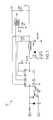
- FIGS. 1A-1Bshow an example circuit diagram of a power sensing and indication circuit with a dual universal serial bus (USB) device connector according to an aspect of the invention.
- USBuniversal serial bus
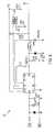
- FIGS. 2A-2Bshow an example circuit diagram of a power sensing and indication circuit with a USB device connector and a USB Type-C device connector according to an aspect of the invention.
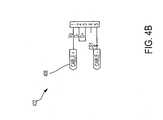
- FIGS. 3A-3Bshow an example circuit diagram of a power sensing and indication circuit with a USB device connector and a lighting USB device connector according to an aspect of the invention.
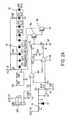
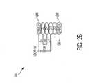
- FIGS. 4A-4Bshow an example circuit diagram of a power sensing and indication circuit with a USB device connector and a micro-USB device connector according to an aspect of the invention.
- FIG. 5shows an example circuit diagram of a controller that drives an electrical charge to the power sensing and indication circuit of FIG. 1 according to an aspect of the invention.
- FIG. 6shows an example circuit diagram of a controller that drives an electrical charge to the power sensing and indication circuit of FIG. 2 according to an aspect of the invention.
- FIG. 7shows an example circuit diagram of a controller that drives an electrical charge to the power sensing and indication circuit of FIGS. 3 according to an aspect of the invention.
- FIG. 8shows an example circuit diagram of a controller that drives an electrical charge to the power sensing and indication circuit of FIG. 4 according to an aspect of the invention.
- FIG. 9Ashows a front perspective view of an example car charging device according to an aspect of the invention.
- FIG. 9Bshows a side perspective view of the example car charging device according to an aspect of the invention.
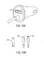
- FIGS. 10A-10Bshows an example car charging device with a connected cable and different device connectors according to an aspect of the invention.
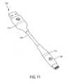
- FIG. 11shows an example charging cable according to an aspect of the invention.
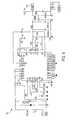
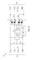
- FIG. 12shows an example circuit diagram of a power sensing and indication circuit for a charging cable according to an aspect of the invention.
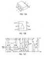
- FIG. 13Ashows an example integrated circuit of the power sensing and indication circuit of FIG. 12 according to an aspect of the invention.
- FIG. 13Bshows the pin connections of the integrated circuit of FIG. 13A according to an aspect of the invention.
- FIG. 13Cshows a block diagram of the integrated circuit of FIG. 13A according to an aspect of the invention.
- a power sensing and indication circuitprovides an indication of a charge of an attached device.
- the power sensing and indication circuitis configurable to provide one or more visual indications to a user to indicate the amount of power in an attached device.
- a personal devicesuch as a smart phone
- a light on the chargermay indicate that the personal device is low on power.
- the chargermay indicate that the personal device is not low on power.
- the chargermay indicate that the personal device is fully charged.
- the chargermay indicate the power level of the device even when the device does not otherwise provide an indication of the power level.
- the indicator of the chargermay be positioned in the user's field of view so that a user does not have to divert their attention, e.g., away from the road, to the personal device.
- the power sensing and indication circuitmay use different colors to represent the different power levels or may use different types of indications, such as a flashing indicator, to represent the different power levels.
- the power sensing and indication circuitsupports different device connectors, such as a universal serial bus (USB), a USB Type-C (USB-C), a lightning USB connector, or a micro-USB connector, that connect to different types of devices.
- USBuniversal serial bus
- USB-CUSB Type-C
- lightning USB connectoror a micro-USB connector
- FIGS. 1A-1B, 2A-2B, 3A-3B and 4A-4Bare circuit diagrams of a power sensing and indication circuit 100 for charging devices.
- the power sensing and indication circuit (“power sensing circuit”) 100 of a chargerincludes one or more device connectors for charging one or more devices, such as a smartphone, a tablet or other personal device, one or more amplifiers, e.g., amplifiers 104 , 106 , one or more transistors, e.g., transistors 118 a - b, or a digital circuit, and multiple light-emitting photo diodes, e.g., the light-emitting photodiodes (LEDs) 108 , 110 .
- LEDslight-emitting photodiodes
- the power sensing circuit 100may be applied to any type of charger, e.g., a car charging device 900 of FIGS. 9-10 .
- a deviceis connected to the car charging device 900 and the charge of the device is less than a threshold value, e.g., less than 95% charged, one or more LEDs emit a first color, such as a white color, that indicates that the charge of the connected device is less than the threshold value and is not fully charged.
- a threshold valuee.g., less than 95% charged
- the one or more LEDsemit a second color, such as a blue color, that indicates that the connected device is fully charged.
- the threshold value for the charge of the device that causes the LEDs to emit a particular color of lightmay vary depending on the device.
- the threshold valuemay range from 85%-95% so that when the charge is less than the threshold value the one or more LEDs emit the first color, such as the white color, and when the charge is greater than or equal to the threshold value the one or more LEDs emit the second color, such as the blue color.
- the one or more LEDsemit a first color when the device connected is between 85%-100% charged, and a second color when the device connected is between 0%-84% charged.
- the one or more LEDsflash, blink or otherwise provide an indication to differentiate between the two ranges of charge.
- the power sensing circuit 100includes one or more device connectors, e.g., device connectors 102 a - b.
- FIGS. 1B, 2B, 3B and 4Bare circuit diagrams of the one or more device connectors that are included in the power sensing circuit 100 and attach to one or more devices.
- the one or more device connectorsinclude one or more Universal Serial Bus (USB) connectors, e.g., Dual USB connector 102 of FIG. 1B or USB connector 204 of FIG. 2A , one or more lightning USB connectors, e.g., lightning USB connector 302 of FIG. 3B , a USB Type-C (USB-C) connector 202 of FIG. 2B and/or a micro USB connector 402 of FIG. 4B .
- USBUniversal Serial Bus
- the one or more device connectorsmay include a first device connector 102 a and a second device connector 102 b.
- the first device connector and the second device connectormay be combined to form a single integrated connector.
- a first device connector 102 amay be integrated with a second device connector 102 b to form the Dual USB connector 102 .
- the first or second device connectorsmay be a lightning USB connector 302 , a USB-C connector 202 , a single USB connector 204 or a micro-USB connector 402 .
- Each of the one or more device connectorshas multiple pins including a voltage input pin (V+), a ground pin (V ⁇ ) and one or more data pins.
- the voltage pin (V+)may receive a charge from a charging device, e.g., a charge of 5 Volts (V)/4.8 Amps (A) for a Dual USB car charger or a Single USB and corded USB-C car charger or a charge of 5V/3.4 A for a Single USB and corded lightning/micro-USB car charger, to deliver the charge to a device connected to the device connector.
- the wattage of the charge from the charging devicemay vary.
- the V1+ pin of the first device connector 102 adelivers a charge to a first device that is connected to the first device connector 102 a.
- the one or more data pinstransfer data between the first device connector 102 a and the first device, and may be connected to an automatic detection device 124 .
- the automatic detection device 124optimizes the charging speed.
- the automatic detection device 124is described in U.S. Pat. No. 9,252,614 and U.S. Pat. No. 9,385,551 which are herein incorporated by reference.
- the ground pin (V ⁇ )may be connected to ground through one or more resistors.
- the power sensing circuit 100includes one or more amplifiers, e.g., amplifiers 104 , 106 .
- One or more amplifiersare connected to the one or more ground pins (V ⁇ ) of the one or more device connectors.
- the non-inverting input port of each of the one or more amplifiersis connected to a respective ground pin of one of the one or more device connectors.
- the inverting input port of each of the one or more amplifiers 104 , 106is connected to a voltage divider 112 and the output voltage of the voltage divider 112 is the voltage at the inverting input port of the amplifiers.
- the non-inverting input port of the first amplifier 104is connected to the ground pin of the first device connector 102 a
- the non-inverting input port of the second amplifier 106is connected to the ground pin of the second device connector 102 b.
- the voltages at the respective ground pinsare the input voltages for the respective non-inverting input ports of the first amplifier 104 and the second amplifier 106 .
- the inverting input port of the first amplifier 104is connected to and in parallel with the voltage divider 112 and the inverting input port of the second amplifier 106 .
- the output voltage of the voltage divider 112is the input voltage of the inverting input ports of the first amplifier 104 and second amplifier 106 .
- the voltage divider 112may include two resistors, a first resistor having a resistance of 68,100 Ohms ( ⁇ ) and a second resistor with a resistance of 332 ⁇ .
- the power sensing circuit 100includes a transistor that is connected to the output port of each of the one or more amplifiers.
- the transistorhas a base terminal, a collector terminal and an emitter terminal.
- the base terminal of the transistormay be connected through one or more resistors to the output port of each of the one or more amplifiers.
- the transistoris configured to connect the collector terminal to the emitter terminal to allow current to flow through when there is a voltage and/or current that flows through the base terminal and out through the emitter terminal.
- the base terminal of transistor 118is connected to the output ports of the amplifiers 104 and 106 through resistors 120 and 122 , respectively.
- the power sensing circuit 100includes a digital circuit, instead of a transistor, that controls the charge that flows through to illuminate the first set or the second set of LEDs 108 , 110 .
- a controllersuch as one of the controllers 500 of FIG. 5, 600 of FIG. 6, 700 of FIG. 7, 800 of FIG. 8 , drives an electrical charge to the one or more devices connected to the one or more device connectors through the power sensing circuit 100 .
- the controllerhas an input charge.
- the input charge at an input voltage port of the controllermay be a charge of 5 Volts (V)/4.8 Amps (A) for a Dual USB car charger or a Single USB and corded USB-C car charger or a charge of 5V/3.4 A for a Single USB and corded lightning/micro-USB car charger, for example.
- the one or more output voltage ports of the controllerare connected to the input pins of the device connector and/or the voltage divider.
- the controller 500 , 600 , 700 or 800drives a voltage of 5V to the voltage divider 112 through one or more resistors 116 that have a combined resistance of 2,000 ⁇ .
- the resulting output voltage of the voltage divider 112may have a charge of 13.5 millivolts (mV) that results from a controller 500 , 600 , 700 or 800 providing a charge of 5V through the one or more resistors 116 and out through the voltage divider 112 and into the inverting input ports of the amplifiers 104 , 106 .
- the controller 500drives a voltage to the input pins of the Dual USB connector 102 .
- the controller 600drives a voltage to the input pin of the USB-C connector 202 through one or more cables 206 and to the input pin of the USB connector 204 .
- the controller 700drives a voltage to the input pin of the lightning USB connector 302 through one or more cables 306 and to the input pin of the USB connector 204 .
- the controller 800drives a voltage to the input pin of the micro-USB connector 402 through one or more cables 406 and to the input pin of the USB connector 204 .
- a first set of photodiodesemit light of a first color.
- a first set of LEDs 108turns on.
- the voltage at the non-inverting input ports being greater than the resulting output voltage of 13.5 mVindicates that the total charge of the attached first and second devices to the first device connector and the second device connector is less than a threshold value, e.g., 95% of the total charge capacity of the attached devices.
- the first set of LEDs 108may emit a white color to indicate to a user of the attached first and/or second devices that the charge is less than the threshold value, e.g., 95% of the total charge capacity of the attached devices.
- the threshold valuemay range from 85%-95%.
- the first set of LEDs 108may turn on when the device connected has a charge between 85%-100% if the threshold value is 85% or between 95%-100% if the threshold value is 95%.
- the different set of LEDsmay include a set of 1, 2, 4 or any other number of LEDs in each set.
- a second set of photodiodesemit light of a second color.
- a second set of LEDs 110turns on.
- the voltage at the non-inverting input ports being less than the resulting output voltage of 13.5 mVindicates that the total charge of the attached first and second devices to the first device connector and the second device connector is greater than a threshold value, e.g., 95% of the total charge capacity of the attached devices.
- the second set of LEDs 110may emit a blue color to indicate to a user of the attached first and second devices that the charge is greater than the threshold value, e.g., 95% of the total charge capacity of the attached devices.
- the second set of LEDs 110may turn on when the device connected has a charge between 0%-84%% if the threshold value is 85% or between 0%-94% if the threshold value is 95%.
- FIG. 9is an illustration of a car charging device 900 .
- the car charging device 900may have a dual USB device connector to charge one or more devices.
- the car charging device 900includes a housing 902 , the power sensing circuit 100 having one or more device connectors, one or more electrical contacts, and an LED power indicator 920 .
- the housing 902houses the power sensing circuit 100 .
- the power sensing circuit 100includes the two device connectors 102 a - b, the first set and second set of LEDs 108 , 110 and the controller 500 .
- the housing 902has a front surface 904 and a body 910 .
- the body 910may be frusto-conical or cylindrical.
- the front surface 904 and the body 910form a cavity within the housing 902 that encloses the power sensing circuit 100 including the device connectors 102 a - b and the first set and second set of LEDs 108 , 110 .
- the front surface 304may have two recessed regions 906 , 908 where the two device connectors 102 a - b, such as a dual USB connector 102 , are exposed.
- the front surface 904may have one or more icons, such as an icon 918 , etched, molded, embossed or debossed into the front surface 904 .
- the body 910has three openings that expose three electrical contacts 912 , 914 and 916 .
- the three electrical contacts 912 , 914 and 916electrically connect to a power source, such as a vehicle outlet, when the car charging device 900 is inserted into the vehicle outlet.
- the LED power indicator 920may be positioned between the front surface 904 of the housing 902 and the body 910 of the housing 902 .
- the LED power indicator 920may be a transparent ring around the edge of the body 910 of the housing 902 .
- the LED power indicator 920surrounds the first set and second set of LEDs 108 , 110 such that when the first set or the second set of LEDs 108 , 110 are turned on the light emitted from the first set or the second set of LEDs 108 , 110 illuminates through the LED power indicator 920 .
- the car charging devicehas a USB connector 1014 and one of a lightning cable connector 1006 , a USB-C connector 1008 or a micro-USB cable connector 1004 to charge one or more devices, as shown in FIGS. 10A-B , for example.
- FIG. 11is an illustration of a charging cable 1100 .
- the charging cable 1100has one or more housings 1106 , a cable portion 1108 and one or more LED power indicators 1110 .
- the charging cable 1100electrically connects the charging device to the charger.
- the one or more housings 1106may house a power sensing circuit, such as the power sensing circuit 1200 of FIG. 12 , and a device connector, such as a USB connector, a USB-C connector, a lightning cable connector, or a micro-USB cable connector.
- the one or more housings 1106may be made of aluminum and prevent bending of the device connector within the housing.
- the one or more housings 1106may be positioned on opposite ends of the charging cable 1100 connected by a cable portion 1108 .
- the cable portion 1108may be braided and may flexible but resistant to bending.
- the one or more LED power indicators 1110may form a transparent ring adjacent to one or more housings 1106 and emit light based on the charge of the connected device when one of the device connectors at the end of the charging cable is inserted into a device and a device connector of a charging device, such as a car charger.
- the first and second set of LEDs 108 , 110may illuminate different colors through the LED power indicators 1110 based on the charge of the one or more connected devices. For example, when a device is connected to one of the device connectors and the charge of the device is less than a threshold value, e.g., the charge is less than 95%, the first set of LEDs 108 emit a first color, such as a white color, that indicates that the charge of the connected device is not fully charged. When the charge is greater than or equal to the threshold value, e.g., greater than or equal to 95% charged, the second set of LEDs 110 emit a second color, such as a blue color, that indicates that the connected device is fully charged.
- the threshold value for the charge of the device that causes the LEDs to emit a particular color of lightmay vary depending on the device.
- the threshold value for the charge of the devicemay be between 85%-95%.
- FIG. 12is a circuit diagram of a power sensing and indication circuit (“cable power sensing circuit”) 1200 for a charging cable, such as the charging cable 1100 .
- the cable power sensing circuit 1200may include any, all or none of the components described in the power sensing circuit 100 .
- the cable power sensing circuit 1200has one or more device connectors, e.g., two device connectors 1202 , 1204 .
- the two device connectors 1202 , 1204are on opposite ends of the cable power sensing circuit 1200 .
- the first device connector 1202is connected to a device that is being charged, such as a tablet, mobile device or other personal device, and the second device connector 1204 to the charger, e.g., the power sensing circuit 100 of the charger.
- the cable power sensing circuit 1200electrically connects the charger to the charging device.
- the cable power sensing circuit 1200includes the multiple sets of LEDs 108 , 110 and an integrated circuit 1206 .
- the integrated circuit 1206has a first input pin (IN+) and a second input pin (IN ⁇ ).
- the integrated circuit 1206compares the voltage at the first input pin to the voltage at the second input pin. If the voltage at the first input pin is greater than the voltage at the second input pin, the first set of LEDs 108 is activated and a first color, such as a white color, is illuminated. If the voltage at the first input pin is greater than the voltage at the second input pin, the second set of LEDs 110 is activated and a second color, such as a blue color, is illuminated.
- the integrated circuit 1206activates the first set of LEDs 108 when the voltage at the first input pin is less than the voltage at the second input pin, and activates the second set of LEDs 110 when the voltage at the first input pin is greater than the voltage at the second input pin.
- the voltage at the second input pinmay be a threshold value, e.g., 13.5 mV.
- the threshold valuemay vary.
- An example of the integrated circuit 1206is shown in FIGS. 13A-C .
Landscapes
- Engineering & Computer Science (AREA)
- Power Engineering (AREA)
- Charge And Discharge Circuits For Batteries Or The Like (AREA)
Abstract
Description
- This application claims priority to and the benefit of U.S. Provisional Patent Application No. 62/383,328 titled “LED CABLE AND CAR CHARGER,” filed on Sep. 2, 2016, and the entirety of which is hereby incorporated by reference herein.
- This specification relates to a system, device and circuit for sensing and providing an indication of a charge in a device.
- Some chargers, such as AC adaptors, car vehicle charger adaptors and other charging cables, have one or more charging indicator lights to indicate to the user when the adaptor is charging a personal device, such as a smartphone, a laptop or other personal device. For example, an AC adaptor for a laptop may have a light indicator that turns on when the AC adaptor is plugged into an electrical socket. The light indicator of the AC adaptor for the laptop is on whenever the AC adaptor is plugged into the electrical socket regardless of whether the AC adaptor is attached to the laptop. Thus, the charging indicator lights indicate that the charger is providing power to the personal device and do not indicate the power level of the personal device.
- Moreover, the charging indicator lights do not indicate to the user when the personal device is fully charged, low on power, and/or operating with enough power. A personal device, however, may have an indicator that shows the different power levels of the personal device. But, the personal device may be located in an inconvenient location that is out of the field of view of the user.
- Accordingly, there is a need for a device that conveniently shows the power level of the personal device.
- In general, one aspect of the subject matter described in this specification is embodied in a power sensing and indication circuit. The power sensing and indication circuit includes a first device connector for charging a first device and having a first pin and a second pin, the first pin of the first device connector being connected to an output voltage port of a controller. The power sensing and indication circuit includes a first amplifier. The first amplifier has an inverting input port, a non-inverting input port and an output port. The non-inverting input port of the first amplifier is connected to the second pin of the first device connector. The power sensing and indication circuit includes a first set of multiple photodiodes for emitting light of a first color and second set of multiple photodiodes for emitting light of a second color. The power sensing and indication circuit includes at least one of a transistor or a digital circuit configured to cause the first set of multiple diodes to emit light of the first color or the second set of multiple photodiodes to emit light of the second color.
- These and other embodiments may optionally include one or more of the following features. The non-inverting input port may have a first voltage and the inverting input port may have a second voltage. The first set of multiple photodiodes may emit light of the first color when the first voltage is greater or equal to the second voltage. The second set of multiple photodiodes may emit light of the second color when the first voltage is less than the second voltage.
- The power sensing and indication circuit may include a second device connector for charging a second device. The second device connector may have a first pin and a second pin. The power sensing and indication circuit may include a second amplifier. The second amplifier may have an inverting input port, a non-inverting input port and an output port. The non-inverting input port of the second amplifier may be connected to the second pin of the second device connector. The non-inverting input port of the first amplifier may have a first voltage and the inverting input port of the first amplifier may have a second voltage. The non-inverting input port of the second amplifier may have a third voltage and the inverting input port of the second amplifier may have a second voltage. The power sensing and indication circuit may include a transistor that may be connected to the output port of the first amplifier and the output port of the second amplifier.
- The first set of multiple photodiodes may emit light of the first color when the first voltage is greater than the second voltage and the third voltage is greater than the second voltage. The second set of multiple photodiodes may emit light of the second color when at least one of the first voltage or the third voltage is less than the second voltage. The second voltage may be 13.5 mV.
- At least one of the first device connector or the second device connector may be a universal serial bus (USB) connector. At least one of the first device connector or the second device connector may be a lightning USB connector, a micro-USB connector or a USB Type-C (USB-C) connector. A cable may connect the lightning USB Connector, the micro-USB connector or the USB-C connector with the controller.
- In another aspect, the subject matter is embodied in a power sensing and indication device for charging devices. The power sensing and indication device includes a controller for providing a charge to a device and having an input voltage port and an output voltage port. The power sensing and indication device includes a power sensing and indication circuit. The power sensing and indication circuit includes a device connector for charging the device and having a first pin and a second pin. The first pin of the first device connector is connected to the output voltage port of the controller. The power sensing and indication circuit includes an amplifier having an inverting input port, a non-inverting input port and an output port. The non-inverting input port of the amplifier is connected to the second pin of the device connector. The power sensing and indication circuit includes a first set of multiple photodiodes for emitting light of a first color and a second set of multiple photodiodes for emitting light of a second color. The power sensing and indication circuit includes a transistor that is configured to cause the first set of multiple photodiodes to emit light of the first color or the second set of multiple photodiodes to emit light of the second color.
- Other systems, methods, features, and advantages of the present invention will be apparent to one skilled in the art upon examination of the following figures and detailed description. Component parts shown in the drawings are not necessarily to scale, and may be exaggerated to better illustrate the important features of the present invention.
FIGS. 1A-1B show an example circuit diagram of a power sensing and indication circuit with a dual universal serial bus (USB) device connector according to an aspect of the invention.FIGS. 2A-2B show an example circuit diagram of a power sensing and indication circuit with a USB device connector and a USB Type-C device connector according to an aspect of the invention.FIGS. 3A-3B show an example circuit diagram of a power sensing and indication circuit with a USB device connector and a lighting USB device connector according to an aspect of the invention.FIGS. 4A-4B show an example circuit diagram of a power sensing and indication circuit with a USB device connector and a micro-USB device connector according to an aspect of the invention.FIG. 5 shows an example circuit diagram of a controller that drives an electrical charge to the power sensing and indication circuit ofFIG. 1 according to an aspect of the invention.FIG. 6 shows an example circuit diagram of a controller that drives an electrical charge to the power sensing and indication circuit ofFIG. 2 according to an aspect of the invention.FIG. 7 shows an example circuit diagram of a controller that drives an electrical charge to the power sensing and indication circuit ofFIGS. 3 according to an aspect of the invention.FIG. 8 shows an example circuit diagram of a controller that drives an electrical charge to the power sensing and indication circuit ofFIG. 4 according to an aspect of the invention.FIG. 9A shows a front perspective view of an example car charging device according to an aspect of the invention.FIG. 9B shows a side perspective view of the example car charging device according to an aspect of the invention.FIGS. 10A-10B shows an example car charging device with a connected cable and different device connectors according to an aspect of the invention.FIG. 11 shows an example charging cable according to an aspect of the invention.FIG. 12 shows an example circuit diagram of a power sensing and indication circuit for a charging cable according to an aspect of the invention.FIG. 13A shows an example integrated circuit of the power sensing and indication circuit ofFIG. 12 according to an aspect of the invention.FIG. 13B shows the pin connections of the integrated circuit ofFIG. 13A according to an aspect of the invention.FIG. 13C shows a block diagram of the integrated circuit ofFIG. 13A according to an aspect of the invention.- Disclosed herein are systems, devices and circuits for sensing and providing an indication of a charge in devices. Particular embodiments of the subject matter described in this specification may be implemented to realize one or more of the following advantages.
- A power sensing and indication circuit provides an indication of a charge of an attached device. The power sensing and indication circuit is configurable to provide one or more visual indications to a user to indicate the amount of power in an attached device. For example, a personal device, such as a smart phone, may be attached to charger that has the power sensing and indication circuit, and when the personal device is low on power, a light on the charger may indicate that the personal device is low on power. When the personal device receives enough power from the charger so that the personal device is no longer low on power, the charger may indicate that the personal device is not low on power. And, when the personal device is fully charged, the charger may indicate that the personal device is fully charged. The charger may indicate the power level of the device even when the device does not otherwise provide an indication of the power level. Moreover, the indicator of the charger may be positioned in the user's field of view so that a user does not have to divert their attention, e.g., away from the road, to the personal device.
- Other benefits and advantages include allowing the charger to display different power levels of the devices, such as a low power level, a charging power level, and/or a fully charged power level. The power sensing and indication circuit may use different colors to represent the different power levels or may use different types of indications, such as a flashing indicator, to represent the different power levels.
- Another benefit and advantage of the power sensing and indication circuit is that it supports different device connectors, such as a universal serial bus (USB), a USB Type-C (USB-C), a lightning USB connector, or a micro-USB connector, that connect to different types of devices. This allows the charger to charge different types of devices and indicate the power levels of the device even if the device does not have an indicator that shows the power level of the device.
FIGS. 1A-1B, 2A-2B, 3A-3B and 4A-4B are circuit diagrams of a power sensing andindication circuit 100 for charging devices. The power sensing and indication circuit (“power sensing circuit”)100 of a charger includes one or more device connectors for charging one or more devices, such as a smartphone, a tablet or other personal device, one or more amplifiers, e.g.,amplifiers - The
power sensing circuit 100 may be applied to any type of charger, e.g., acar charging device 900 ofFIGS. 9-10 . When a device is connected to thecar charging device 900 and the charge of the device is less than a threshold value, e.g., less than 95% charged, one or more LEDs emit a first color, such as a white color, that indicates that the charge of the connected device is less than the threshold value and is not fully charged. When the charge is greater than or equal to the threshold value, e.g., greater than or equal to 95% charged, the one or more LEDs emit a second color, such as a blue color, that indicates that the connected device is fully charged. The threshold value for the charge of the device that causes the LEDs to emit a particular color of light may vary depending on the device. The threshold value may range from 85%-95% so that when the charge is less than the threshold value the one or more LEDs emit the first color, such as the white color, and when the charge is greater than or equal to the threshold value the one or more LEDs emit the second color, such as the blue color. In some implementations, the one or more LEDs emit a first color when the device connected is between 85%-100% charged, and a second color when the device connected is between 0%-84% charged. In some implementations, the one or more LEDs flash, blink or otherwise provide an indication to differentiate between the two ranges of charge. - The
power sensing circuit 100 includes one or more device connectors, e.g.,device connectors 102a-b.FIGS. 1B, 2B, 3B and 4B are circuit diagrams of the one or more device connectors that are included in thepower sensing circuit 100 and attach to one or more devices. The one or more device connectors include one or more Universal Serial Bus (USB) connectors, e.g.,Dual USB connector 102 ofFIG. 1B orUSB connector 204 ofFIG. 2A , one or more lightning USB connectors, e.g.,lightning USB connector 302 ofFIG. 3B , a USB Type-C (USB-C)connector 202 ofFIG. 2B and/or amicro USB connector 402 ofFIG. 4B . The one or more device connectors may include afirst device connector 102aand asecond device connector 102b.The first device connector and the second device connector may be combined to form a single integrated connector. For example, afirst device connector 102amay be integrated with asecond device connector 102bto form theDual USB connector 102. The first or second device connectors may be alightning USB connector 302, a USB-C connector 202, asingle USB connector 204 or amicro-USB connector 402. - Each of the one or more device connectors has multiple pins including a voltage input pin (V+), a ground pin (V−) and one or more data pins. The voltage pin (V+) may receive a charge from a charging device, e.g., a charge of 5 Volts (V)/4.8 Amps (A) for a Dual USB car charger or a Single USB and corded USB-C car charger or a charge of 5V/3.4 A for a Single USB and corded lightning/micro-USB car charger, to deliver the charge to a device connected to the device connector. The wattage of the charge from the charging device may vary. For example, the V1+ pin of the
first device connector 102adelivers a charge to a first device that is connected to thefirst device connector 102a.The one or more data pins transfer data between thefirst device connector 102aand the first device, and may be connected to anautomatic detection device 124. Theautomatic detection device 124 optimizes the charging speed. Theautomatic detection device 124 is described in U.S. Pat. No. 9,252,614 and U.S. Pat. No. 9,385,551 which are herein incorporated by reference. The ground pin (V−) may be connected to ground through one or more resistors. - The
power sensing circuit 100 includes one or more amplifiers, e.g.,amplifiers more amplifiers voltage divider 112 and the output voltage of thevoltage divider 112 is the voltage at the inverting input port of the amplifiers. For example, the non-inverting input port of thefirst amplifier 104 is connected to the ground pin of thefirst device connector 102a,and the non-inverting input port of thesecond amplifier 106 is connected to the ground pin of thesecond device connector 102b.The voltages at the respective ground pins are the input voltages for the respective non-inverting input ports of thefirst amplifier 104 and thesecond amplifier 106. The inverting input port of thefirst amplifier 104 is connected to and in parallel with thevoltage divider 112 and the inverting input port of thesecond amplifier 106. The output voltage of thevoltage divider 112 is the input voltage of the inverting input ports of thefirst amplifier 104 andsecond amplifier 106. Thevoltage divider 112 may include two resistors, a first resistor having a resistance of 68,100 Ohms (Ω) and a second resistor with a resistance of 332 Ω. - The
power sensing circuit 100 includes a transistor that is connected to the output port of each of the one or more amplifiers. The transistor has a base terminal, a collector terminal and an emitter terminal. The base terminal of the transistor may be connected through one or more resistors to the output port of each of the one or more amplifiers. The transistor is configured to connect the collector terminal to the emitter terminal to allow current to flow through when there is a voltage and/or current that flows through the base terminal and out through the emitter terminal. For example, the base terminal of transistor118 is connected to the output ports of theamplifiers resistors LEDs 108 to emit a white light, otherwise, a charge flows through and illuminates the second set ofLEDs 110 to emit a blue light. In some implementations, thepower sensing circuit 100 includes a digital circuit, instead of a transistor, that controls the charge that flows through to illuminate the first set or the second set ofLEDs - A controller, such as one of the
controllers 500 ofFIG. 5, 600 ofFIG. 6, 700 ofFIG. 7, 800 ofFIG. 8 , drives an electrical charge to the one or more devices connected to the one or more device connectors through thepower sensing circuit 100. The controller has an input charge. The input charge at an input voltage port of the controller may be a charge of 5 Volts (V)/4.8 Amps (A) for a Dual USB car charger or a Single USB and corded USB-C car charger or a charge of 5V/3.4 A for a Single USB and corded lightning/micro-USB car charger, for example. The one or more output voltage ports of the controller are connected to the input pins of the device connector and/or the voltage divider. For example, thecontroller voltage divider 112 through one ormore resistors 116 that have a combined resistance of 2,000 Ω. The resulting output voltage of thevoltage divider 112 may have a charge of 13.5 millivolts (mV) that results from acontroller more resistors 116 and out through thevoltage divider 112 and into the inverting input ports of theamplifiers - The
controller 500 drives a voltage to the input pins of theDual USB connector 102. Thecontroller 600 drives a voltage to the input pin of the USB-C connector 202 through one ormore cables 206 and to the input pin of theUSB connector 204. Thecontroller 700 drives a voltage to the input pin of thelightning USB connector 302 through one ormore cables 306 and to the input pin of theUSB connector 204. Thecontroller 800 drives a voltage to the input pin of themicro-USB connector 402 through one ormore cables 406 and to the input pin of theUSB connector 204. - When the voltage driven through the non-inverting input ports of the one or more amplifiers is greater than or equal to the voltage driven through the inverting input ports, a first set of photodiodes emit light of a first color. For example, when the voltage driven through the non-inverting input ports of the
amplifiers voltage divider 112, a first set ofLEDs 108 turns on. The voltage at the non-inverting input ports being greater than the resulting output voltage of 13.5 mV indicates that the total charge of the attached first and second devices to the first device connector and the second device connector is less than a threshold value, e.g., 95% of the total charge capacity of the attached devices. The first set ofLEDs 108 may emit a white color to indicate to a user of the attached first and/or second devices that the charge is less than the threshold value, e.g., 95% of the total charge capacity of the attached devices. The threshold value may range from 85%-95%. In some implementations, the first set ofLEDs 108 may turn on when the device connected has a charge between 85%-100% if the threshold value is 85% or between 95%-100% if the threshold value is 95%. The different set of LEDs may include a set of 1, 2, 4 or any other number of LEDs in each set. - When the voltage driven through the non-inverting input ports of the one or more amplifiers is less than the voltage driven through the inverting input ports, a second set of photodiodes emit light of a second color. For example, when the voltage driven through the non-inverting input ports of the
amplifiers voltage divider 112, a second set ofLEDs 110 turns on. The voltage at the non-inverting input ports being less than the resulting output voltage of 13.5 mV indicates that the total charge of the attached first and second devices to the first device connector and the second device connector is greater than a threshold value, e.g., 95% of the total charge capacity of the attached devices. The second set ofLEDs 110 may emit a blue color to indicate to a user of the attached first and second devices that the charge is greater than the threshold value, e.g., 95% of the total charge capacity of the attached devices. In some implementations, the second set ofLEDs 110 may turn on when the device connected has a charge between 0%-84%% if the threshold value is 85% or between 0%-94% if the threshold value is 95%. FIG. 9 is an illustration of acar charging device 900. Thecar charging device 900 may have a dual USB device connector to charge one or more devices. Thecar charging device 900 includes ahousing 902, thepower sensing circuit 100 having one or more device connectors, one or more electrical contacts, and anLED power indicator 920.- The
housing 902 houses thepower sensing circuit 100. Thepower sensing circuit 100 includes the twodevice connectors 102a-b,the first set and second set ofLEDs controller 500. Thehousing 902 has afront surface 904 and abody 910. Thebody 910 may be frusto-conical or cylindrical. Thefront surface 904 and thebody 910 form a cavity within thehousing 902 that encloses thepower sensing circuit 100 including thedevice connectors 102a-band the first set and second set ofLEDs regions device connectors 102a-b,such as adual USB connector 102, are exposed. Thefront surface 904 may have one or more icons, such as anicon 918, etched, molded, embossed or debossed into thefront surface 904. Thebody 910 has three openings that expose threeelectrical contacts electrical contacts car charging device 900 is inserted into the vehicle outlet. - The
LED power indicator 920 may be positioned between thefront surface 904 of thehousing 902 and thebody 910 of thehousing 902. TheLED power indicator 920 may be a transparent ring around the edge of thebody 910 of thehousing 902. TheLED power indicator 920 surrounds the first set and second set ofLEDs LEDs LEDs LED power indicator 920. - In some implementations, the car charging device has a
USB connector 1014 and one of alightning cable connector 1006, a USB-C connector 1008 or amicro-USB cable connector 1004 to charge one or more devices, as shown inFIGS. 10A-B , for example. FIG. 11 is an illustration of a chargingcable 1100. The chargingcable 1100 has one ormore housings 1106, acable portion 1108 and one or moreLED power indicators 1110. The chargingcable 1100 electrically connects the charging device to the charger. The one ormore housings 1106 may house a power sensing circuit, such as the power sensing circuit1200 ofFIG. 12 , and a device connector, such as a USB connector, a USB-C connector, a lightning cable connector, or a micro-USB cable connector. The one ormore housings 1106 may be made of aluminum and prevent bending of the device connector within the housing. The one ormore housings 1106 may be positioned on opposite ends of the chargingcable 1100 connected by acable portion 1108. Thecable portion 1108 may be braided and may flexible but resistant to bending. The one or moreLED power indicators 1110 may form a transparent ring adjacent to one ormore housings 1106 and emit light based on the charge of the connected device when one of the device connectors at the end of the charging cable is inserted into a device and a device connector of a charging device, such as a car charger.- The first and second set of
LEDs LED power indicators 1110 based on the charge of the one or more connected devices. For example, when a device is connected to one of the device connectors and the charge of the device is less than a threshold value, e.g., the charge is less than 95%, the first set ofLEDs 108 emit a first color, such as a white color, that indicates that the charge of the connected device is not fully charged. When the charge is greater than or equal to the threshold value, e.g., greater than or equal to 95% charged, the second set ofLEDs 110 emit a second color, such as a blue color, that indicates that the connected device is fully charged. The threshold value for the charge of the device that causes the LEDs to emit a particular color of light may vary depending on the device. The threshold value for the charge of the device may be between 85%-95%. FIG. 12 is a circuit diagram of a power sensing and indication circuit (“cable power sensing circuit”)1200 for a charging cable, such as the chargingcable 1100. The cable power sensing circuit1200 may include any, all or none of the components described in thepower sensing circuit 100. The cable power sensing circuit1200 has one or more device connectors, e.g., twodevice connectors device connectors first device connector 1202 is connected to a device that is being charged, such as a tablet, mobile device or other personal device, and thesecond device connector 1204 to the charger, e.g., thepower sensing circuit 100 of the charger. The cable power sensing circuit1200 electrically connects the charger to the charging device.- The cable power sensing circuit1200 includes the multiple sets of
LEDs integrated circuit 1206. Theintegrated circuit 1206 has a first input pin (IN+) and a second input pin (IN−). Theintegrated circuit 1206 compares the voltage at the first input pin to the voltage at the second input pin. If the voltage at the first input pin is greater than the voltage at the second input pin, the first set ofLEDs 108 is activated and a first color, such as a white color, is illuminated. If the voltage at the first input pin is greater than the voltage at the second input pin, the second set ofLEDs 110 is activated and a second color, such as a blue color, is illuminated. In some implementations, theintegrated circuit 1206 activates the first set ofLEDs 108 when the voltage at the first input pin is less than the voltage at the second input pin, and activates the second set ofLEDs 110 when the voltage at the first input pin is greater than the voltage at the second input pin. The voltage at the second input pin may be a threshold value, e.g., 13.5 mV. The threshold value may vary. An example of theintegrated circuit 1206 is shown inFIGS. 13A-C . - Exemplary embodiments of the methods/systems have been disclosed in an illustrative style. Accordingly, the terminology employed throughout should be read in a non-limiting manner. Although minor modifications to the teachings herein will occur to those well versed in the art, it shall be understood that what is intended to be circumscribed within the scope of the patent warranted hereon are all such embodiments that reasonably fall within the scope of the advancement to the art hereby contributed, and that that scope shall not be restricted, except in light of the appended claims and their equivalents.
Claims (21)
Priority Applications (1)
| Application Number | Priority Date | Filing Date | Title |
|---|---|---|---|
| US15/669,781US11146084B2 (en) | 2016-09-02 | 2017-08-04 | Car charger with cable and LED activated when devices are connected to connectors |
Applications Claiming Priority (2)
| Application Number | Priority Date | Filing Date | Title |
|---|---|---|---|
| US201662383328P | 2016-09-02 | 2016-09-02 | |
| US15/669,781US11146084B2 (en) | 2016-09-02 | 2017-08-04 | Car charger with cable and LED activated when devices are connected to connectors |
Publications (2)
| Publication Number | Publication Date |
|---|---|
| US20180069413A1true US20180069413A1 (en) | 2018-03-08 |
| US11146084B2 US11146084B2 (en) | 2021-10-12 |
Family
ID=61280869
Family Applications (1)
| Application Number | Title | Priority Date | Filing Date |
|---|---|---|---|
| US15/669,781Active2038-11-16US11146084B2 (en) | 2016-09-02 | 2017-08-04 | Car charger with cable and LED activated when devices are connected to connectors |
Country Status (1)
| Country | Link |
|---|---|
| US (1) | US11146084B2 (en) |
Cited By (8)
| Publication number | Priority date | Publication date | Assignee | Title |
|---|---|---|---|---|
| US20190074703A1 (en)* | 2017-09-06 | 2019-03-07 | Inventec (Pudong) Technology Corporation | Smart jewelry device and charger of the same |
| US10377319B2 (en)* | 2017-10-04 | 2019-08-13 | Ford Global Technologies, Llc | Holder for mobile device |
| WO2019187798A1 (en)* | 2018-03-29 | 2019-10-03 | 本田技研工業株式会社 | Usb terminal unit arrangement structure for saddle riding-type vehicle |
| CN111600482A (en)* | 2020-06-30 | 2020-08-28 | 京东方科技集团股份有限公司 | Display Motherboards and Display Units |
| CN112290633A (en)* | 2020-10-28 | 2021-01-29 | 广东健奥科技有限公司 | Circuit and method for indicating power supply by using bicolor light-emitting diode and oximeter |
| US20210031640A1 (en)* | 2014-07-03 | 2021-02-04 | The Noco Company | Jump starting apparatus |
| GB2588472A (en)* | 2019-10-24 | 2021-04-28 | Techtronic Cordless Gp | Battery charger |
| EP4568061A3 (en)* | 2023-12-07 | 2025-08-13 | Deutsche Telekom AG | Charging device for mobile terminal |
Citations (13)
| Publication number | Priority date | Publication date | Assignee | Title |
|---|---|---|---|---|
| US4173733A (en)* | 1977-05-02 | 1979-11-06 | General Electric Company | Battery charger with liquid crystal charge current indicator |
| US4896120A (en)* | 1986-03-24 | 1990-01-23 | Zvi Kamil | Instrumentation amplifier arrangement |
| US6095661A (en)* | 1998-03-19 | 2000-08-01 | Ppt Vision, Inc. | Method and apparatus for an L.E.D. flashlight |
| US20060038803A1 (en)* | 2004-08-20 | 2006-02-23 | Semiconductor Components Industries, Llc | LED control method and structure therefor |
| US20080150480A1 (en)* | 2006-10-13 | 2008-06-26 | Amir Navid | Video game controller charging system |
| US20080231229A1 (en)* | 2007-03-19 | 2008-09-25 | Takao Aradachi | Charging Device |
| US20080278119A1 (en)* | 2007-05-11 | 2008-11-13 | Dusan Veselic | Battery charger for a handheld computing device and an external battery |
| US20110006684A1 (en)* | 2007-03-22 | 2011-01-13 | Johnson Controls Technology Company | Lighting devices |
| US20110109245A1 (en)* | 2010-12-14 | 2011-05-12 | Lin Yung Lin | Circuits and methods for driving light sources |
| US20160268731A1 (en)* | 2015-03-12 | 2016-09-15 | Streamlight, Inc. | Usb connector usable with a battery charger and otherwise |
| US9538598B2 (en)* | 2013-12-19 | 2017-01-03 | Shenzhen China Star Optoelectronics Technology Co., Ltd | Backlight adjustment circuit and electronic device |
| US20170012448A1 (en)* | 2014-09-09 | 2017-01-12 | Halo International SEZC Ltd. | Multi-functional portable power charger |
| US20170127726A1 (en)* | 2014-06-30 | 2017-05-11 | Kimree Hi-Tech Inc. | Control circuit, electronic cigarette and method for controlling electronic cigarette |
Family Cites Families (39)
| Publication number | Priority date | Publication date | Assignee | Title |
|---|---|---|---|---|
| US4006396A (en)* | 1974-01-18 | 1977-02-01 | Motorola, Inc. | Universal battery charging apparatus |
| JPS63247668A (en)* | 1987-04-02 | 1988-10-14 | Sharp Corp | Voltage level discrimination device |
| US5105180A (en)* | 1990-02-12 | 1992-04-14 | Asahi Research Corporation | Combination light unit and battery monitor device |
| US5734254A (en)* | 1996-12-06 | 1998-03-31 | Hewlett-Packard Company | Battery pack and charging system for a portable electronic device |
| JPH10341273A (en)* | 1997-06-05 | 1998-12-22 | Nec Corp | Charging display device for portable telephone set |
| JP3905418B2 (en)* | 2001-05-18 | 2007-04-18 | セイコーインスツル株式会社 | Power supply device and electronic device |
| US6956487B2 (en)* | 2002-08-23 | 2005-10-18 | Motorola, Inc. | Battery charging status indication circuit |
| KR101340905B1 (en)* | 2006-05-02 | 2013-12-13 | 코닌클리케 필립스 엔.브이. | Light emitting diode circuit and arrangement and device |
| US7550951B2 (en)* | 2006-10-03 | 2009-06-23 | Asian Power Devices Inc. | Two-step battery charger |
| KR20090021518A (en)* | 2007-08-27 | 2009-03-04 | 삼성전자주식회사 | Multi charging device and method |
| WO2009035531A2 (en)* | 2007-09-07 | 2009-03-19 | Johnson Controls - Saft Advanced Power Solutions Llc | Battery charging system |
| JP2009075902A (en)* | 2007-09-21 | 2009-04-09 | Fujitsu Ltd | Power device and storage device |
| US8054004B2 (en)* | 2008-03-07 | 2011-11-08 | Tai-Her Yang | Bipolar (dis)charging LED drive method and circuit thereof |
| WO2010013177A1 (en)* | 2008-07-29 | 2010-02-04 | Koninklijke Philips Electronics N.V. | Illumination device comprising multiple leds |
| US8569956B2 (en)* | 2009-06-04 | 2013-10-29 | Point Somee Limited Liability Company | Apparatus, method and system for providing AC line power to lighting devices |
| US9472955B2 (en)* | 2009-08-19 | 2016-10-18 | Keene Jones | Emergency light and charger system |
| US20110095728A1 (en)* | 2009-10-28 | 2011-04-28 | Superior Communications, Inc. | Method and apparatus for recharging batteries in a more efficient manner |
| US8242751B2 (en)* | 2010-06-28 | 2012-08-14 | Jen-Yen Yen | Charging device for alkaline battery |
| US9246340B2 (en)* | 2011-02-11 | 2016-01-26 | Intel Corporation | Battery pack |
| US9180783B1 (en)* | 2011-04-22 | 2015-11-10 | Penilla Angel A | Methods and systems for electric vehicle (EV) charge location color-coded charge state indicators, cloud applications and user notifications |
| US8884553B2 (en)* | 2011-10-19 | 2014-11-11 | Justin Hai | Current monitor for indicating condition of attached electrical apparatus |
| US9252615B2 (en)* | 2011-11-07 | 2016-02-02 | Superior Communications, Inc. | Automatic mobile device detector |
| US20140275874A1 (en)* | 2013-03-14 | 2014-09-18 | Covidien Lp | System and method for charging a wireless pulse oximeter |
| CN203491727U (en)* | 2013-07-11 | 2014-03-19 | 向智勇 | USB charger for electronic cigarette |
| US9583968B2 (en)* | 2013-11-21 | 2017-02-28 | Ford Global Technologies, Llc | Photoluminescent disinfecting and charging bin |
| US9711979B2 (en)* | 2014-03-12 | 2017-07-18 | Mitsubishi Electric Corporation | Power supply system |
| US9780600B2 (en)* | 2014-06-27 | 2017-10-03 | Superior Communications, Inc. | Method and apparatus for wirelessly recharging batteries |
| US10320202B2 (en)* | 2014-09-30 | 2019-06-11 | Johnson Controls Technology Company | Battery system bi-stable relay control |
| US9569949B1 (en)* | 2014-10-27 | 2017-02-14 | Daniel Jonathan Jones | Smartphone charging alarm feedback device |
| US20160141903A1 (en)* | 2014-11-19 | 2016-05-19 | Superior Communications, Inc. | Power charger for mobile devices |
| US9847658B2 (en)* | 2014-12-31 | 2017-12-19 | Meridian Design, Inc. | Systems and methods for performing battery management |
| US10825417B2 (en)* | 2015-04-10 | 2020-11-03 | Ossia Inc. | Wirelessly powered electronic display apparatuses |
| US10807547B2 (en)* | 2016-02-10 | 2020-10-20 | Denso Corporation | On-board power supply apparatus |
| US9789783B2 (en)* | 2016-03-18 | 2017-10-17 | Ford Global Technologies, Llc | Hybrid/electric vehicle charge port door |
| US10173604B2 (en)* | 2016-08-24 | 2019-01-08 | Ford Global Technologies, Llc | Illuminated vehicle console |
| US11026311B2 (en)* | 2017-06-19 | 2021-06-01 | Abl Ip Holding Llc | Emergency lighting system with power rollback |
| AU2018342093B2 (en)* | 2017-09-26 | 2023-09-07 | Stryker Corporation | System and method for wirelessly charging a medical device battery |
| TWI670928B (en)* | 2018-10-03 | 2019-09-01 | 財團法人工業技術研究院 | Solar photovoltaic system |
| US10357063B1 (en)* | 2018-10-03 | 2019-07-23 | Db Innovation Inc. | Vaporization device charger |
- 2017
- 2017-08-04USUS15/669,781patent/US11146084B2/enactiveActive
Patent Citations (13)
| Publication number | Priority date | Publication date | Assignee | Title |
|---|---|---|---|---|
| US4173733A (en)* | 1977-05-02 | 1979-11-06 | General Electric Company | Battery charger with liquid crystal charge current indicator |
| US4896120A (en)* | 1986-03-24 | 1990-01-23 | Zvi Kamil | Instrumentation amplifier arrangement |
| US6095661A (en)* | 1998-03-19 | 2000-08-01 | Ppt Vision, Inc. | Method and apparatus for an L.E.D. flashlight |
| US20060038803A1 (en)* | 2004-08-20 | 2006-02-23 | Semiconductor Components Industries, Llc | LED control method and structure therefor |
| US20080150480A1 (en)* | 2006-10-13 | 2008-06-26 | Amir Navid | Video game controller charging system |
| US20080231229A1 (en)* | 2007-03-19 | 2008-09-25 | Takao Aradachi | Charging Device |
| US20110006684A1 (en)* | 2007-03-22 | 2011-01-13 | Johnson Controls Technology Company | Lighting devices |
| US20080278119A1 (en)* | 2007-05-11 | 2008-11-13 | Dusan Veselic | Battery charger for a handheld computing device and an external battery |
| US20110109245A1 (en)* | 2010-12-14 | 2011-05-12 | Lin Yung Lin | Circuits and methods for driving light sources |
| US9538598B2 (en)* | 2013-12-19 | 2017-01-03 | Shenzhen China Star Optoelectronics Technology Co., Ltd | Backlight adjustment circuit and electronic device |
| US20170127726A1 (en)* | 2014-06-30 | 2017-05-11 | Kimree Hi-Tech Inc. | Control circuit, electronic cigarette and method for controlling electronic cigarette |
| US20170012448A1 (en)* | 2014-09-09 | 2017-01-12 | Halo International SEZC Ltd. | Multi-functional portable power charger |
| US20160268731A1 (en)* | 2015-03-12 | 2016-09-15 | Streamlight, Inc. | Usb connector usable with a battery charger and otherwise |
Cited By (15)
| Publication number | Priority date | Publication date | Assignee | Title |
|---|---|---|---|---|
| US11766945B2 (en)* | 2014-07-03 | 2023-09-26 | The Noco Company | Jump starting apparatus |
| US12157381B2 (en)* | 2014-07-03 | 2024-12-03 | The Noco Company | Jump starting apparatus |
| US20230365011A1 (en)* | 2014-07-03 | 2023-11-16 | The Noco Company | Jump Starting Apparatus |
| US20210031640A1 (en)* | 2014-07-03 | 2021-02-04 | The Noco Company | Jump starting apparatus |
| US10566812B2 (en)* | 2017-09-06 | 2020-02-18 | Inventec (Pudong) Technology Corporation | Smart jewelry device and charger of the same |
| US20190074703A1 (en)* | 2017-09-06 | 2019-03-07 | Inventec (Pudong) Technology Corporation | Smart jewelry device and charger of the same |
| US10377319B2 (en)* | 2017-10-04 | 2019-08-13 | Ford Global Technologies, Llc | Holder for mobile device |
| WO2019187798A1 (en)* | 2018-03-29 | 2019-10-03 | 本田技研工業株式会社 | Usb terminal unit arrangement structure for saddle riding-type vehicle |
| TWI710485B (en)* | 2018-03-29 | 2020-11-21 | 日商本田技研工業股份有限公司 | Usb terminal unit arrangement structure of saddle-ride type vehicle |
| JPWO2019187798A1 (en)* | 2018-03-29 | 2021-03-11 | 本田技研工業株式会社 | USB terminal unit layout structure for saddle-riding vehicles |
| JP7015379B2 (en) | 2018-03-29 | 2022-02-08 | 本田技研工業株式会社 | USB terminal unit layout structure for saddle-riding vehicles |
| GB2588472A (en)* | 2019-10-24 | 2021-04-28 | Techtronic Cordless Gp | Battery charger |
| CN111600482A (en)* | 2020-06-30 | 2020-08-28 | 京东方科技集团股份有限公司 | Display Motherboards and Display Units |
| CN112290633A (en)* | 2020-10-28 | 2021-01-29 | 广东健奥科技有限公司 | Circuit and method for indicating power supply by using bicolor light-emitting diode and oximeter |
| EP4568061A3 (en)* | 2023-12-07 | 2025-08-13 | Deutsche Telekom AG | Charging device for mobile terminal |
Also Published As
| Publication number | Publication date |
|---|---|
| US11146084B2 (en) | 2021-10-12 |
Similar Documents
| Publication | Publication Date | Title |
|---|---|---|
| US11146084B2 (en) | Car charger with cable and LED activated when devices are connected to connectors | |
| CA2860435C (en) | Travel nightlight with usb charger | |
| US9312704B2 (en) | USB wall plate charger | |
| US20190020158A1 (en) | Modular electrical receptacle | |
| US9028122B2 (en) | Lighted electrical connector assembly | |
| US9083192B2 (en) | Current selectable USB charger | |
| US6628535B1 (en) | Voltage converter with selectable DC output voltage level | |
| US6733333B1 (en) | Transmission cable having operation status indicator means | |
| US7575438B2 (en) | Trailer towing connector with lighting circuit ground path | |
| CN105518967B (en) | Apparatus and method for changing current limit | |
| US20150303821A1 (en) | Wall socket | |
| WO2018040381A1 (en) | Reversible plugging-recognizing power supply device and smart charging device | |
| TWI655536B (en) | Device and method for functional use with C-type universal serial bus (USB-C), and related non-transitory computer readable storage media | |
| JP3196494U (en) | USB cable | |
| CN209329712U (en) | Charging device with charging indication | |
| US20150357919A1 (en) | Method and system for variable output power supply | |
| US9028271B2 (en) | Electrical connector with integrated indicator | |
| CN206332602U (en) | Positive anti-plug can recognize that supply unit and intelligent charger | |
| US20140342600A1 (en) | Automotive adapter with cord retainer | |
| US11735938B2 (en) | Power assembly and methods thereof | |
| US9709611B1 (en) | Multiple electric socket power strip with power meter | |
| US9553464B2 (en) | In-vehicle-mounted charging device | |
| US9071022B2 (en) | Power plug having a universal serial bus port for an electrical appliance | |
| US20160352053A1 (en) | Indicator Wafer | |
| CN216934708U (en) | Electronic building block system |
Legal Events
| Date | Code | Title | Description |
|---|---|---|---|
| AS | Assignment | Owner name:SUPERIOR COMMUNICATIONS, INC., CALIFORNIA Free format text:ASSIGNMENT OF ASSIGNORS INTEREST;ASSIGNORS:CHEN, GEORGE;SENTOSA, SAMUEL;SU, DAVID;REEL/FRAME:043209/0084 Effective date:20160902 | |
| STPP | Information on status: patent application and granting procedure in general | Free format text:DOCKETED NEW CASE - READY FOR EXAMINATION | |
| AS | Assignment | Owner name:BANK OF AMERICA, N.A., AS AGENT, OREGON Free format text:SECURITY INTEREST;ASSIGNOR:SUPERIOR COMMUNICATIONS, INC.;REEL/FRAME:049167/0431 Effective date:20190509 | |
| STPP | Information on status: patent application and granting procedure in general | Free format text:NON FINAL ACTION MAILED | |
| STPP | Information on status: patent application and granting procedure in general | Free format text:RESPONSE TO NON-FINAL OFFICE ACTION ENTERED AND FORWARDED TO EXAMINER | |
| STPP | Information on status: patent application and granting procedure in general | Free format text:FINAL REJECTION MAILED | |
| STPP | Information on status: patent application and granting procedure in general | Free format text:DOCKETED NEW CASE - READY FOR EXAMINATION | |
| STPP | Information on status: patent application and granting procedure in general | Free format text:NON FINAL ACTION MAILED | |
| STPP | Information on status: patent application and granting procedure in general | Free format text:NON FINAL ACTION MAILED | |
| STPP | Information on status: patent application and granting procedure in general | Free format text:RESPONSE TO NON-FINAL OFFICE ACTION ENTERED AND FORWARDED TO EXAMINER | |
| STPP | Information on status: patent application and granting procedure in general | Free format text:EX PARTE QUAYLE ACTION MAILED | |
| STPP | Information on status: patent application and granting procedure in general | Free format text:RESPONSE TO EX PARTE QUAYLE ACTION ENTERED AND FORWARDED TO EXAMINER | |
| STPP | Information on status: patent application and granting procedure in general | Free format text:NOTICE OF ALLOWANCE MAILED -- APPLICATION RECEIVED IN OFFICE OF PUBLICATIONS | |
| STPP | Information on status: patent application and granting procedure in general | Free format text:AWAITING TC RESP., ISSUE FEE NOT PAID | |
| STPP | Information on status: patent application and granting procedure in general | Free format text:NOTICE OF ALLOWANCE MAILED -- APPLICATION RECEIVED IN OFFICE OF PUBLICATIONS | |
| STPP | Information on status: patent application and granting procedure in general | Free format text:PUBLICATIONS -- ISSUE FEE PAYMENT VERIFIED | |
| STCF | Information on status: patent grant | Free format text:PATENTED CASE | |
| MAFP | Maintenance fee payment | Free format text:PAYMENT OF MAINTENANCE FEE, 4TH YR, SMALL ENTITY (ORIGINAL EVENT CODE: M2551); ENTITY STATUS OF PATENT OWNER: SMALL ENTITY Year of fee payment:4 |