US20170108282A1 - Heat exchanger - Google Patents
Heat exchangerDownload PDFInfo
- Publication number
- US20170108282A1 US20170108282A1US15/297,486US201615297486AUS2017108282A1US 20170108282 A1US20170108282 A1US 20170108282A1US 201615297486 AUS201615297486 AUS 201615297486AUS 2017108282 A1US2017108282 A1US 2017108282A1
- Authority
- US
- United States
- Prior art keywords
- throttle valve
- heat exchanger
- valve
- shaft
- bypass tube
- Prior art date
- Legal status (The legal status is an assumption and is not a legal conclusion. Google has not performed a legal analysis and makes no representation as to the accuracy of the status listed.)
- Granted
Links
Images


Classifications
- F—MECHANICAL ENGINEERING; LIGHTING; HEATING; WEAPONS; BLASTING
- F28—HEAT EXCHANGE IN GENERAL
- F28D—HEAT-EXCHANGE APPARATUS, NOT PROVIDED FOR IN ANOTHER SUBCLASS, IN WHICH THE HEAT-EXCHANGE MEDIA DO NOT COME INTO DIRECT CONTACT
- F28D7/00—Heat-exchange apparatus having stationary tubular conduit assemblies for both heat-exchange media, the media being in contact with different sides of a conduit wall
- F28D7/16—Heat-exchange apparatus having stationary tubular conduit assemblies for both heat-exchange media, the media being in contact with different sides of a conduit wall the conduits being arranged in parallel spaced relation
- F28D7/1607—Heat-exchange apparatus having stationary tubular conduit assemblies for both heat-exchange media, the media being in contact with different sides of a conduit wall the conduits being arranged in parallel spaced relation with particular pattern of flow of the heat exchange media, e.g. change of flow direction
- F—MECHANICAL ENGINEERING; LIGHTING; HEATING; WEAPONS; BLASTING
- F28—HEAT EXCHANGE IN GENERAL
- F28D—HEAT-EXCHANGE APPARATUS, NOT PROVIDED FOR IN ANOTHER SUBCLASS, IN WHICH THE HEAT-EXCHANGE MEDIA DO NOT COME INTO DIRECT CONTACT
- F28D7/00—Heat-exchange apparatus having stationary tubular conduit assemblies for both heat-exchange media, the media being in contact with different sides of a conduit wall
- F28D7/10—Heat-exchange apparatus having stationary tubular conduit assemblies for both heat-exchange media, the media being in contact with different sides of a conduit wall the conduits being arranged one within the other, e.g. concentrically
- F28D7/106—Heat-exchange apparatus having stationary tubular conduit assemblies for both heat-exchange media, the media being in contact with different sides of a conduit wall the conduits being arranged one within the other, e.g. concentrically consisting of two coaxial conduits or modules of two coaxial conduits
- F—MECHANICAL ENGINEERING; LIGHTING; HEATING; WEAPONS; BLASTING
- F02—COMBUSTION ENGINES; HOT-GAS OR COMBUSTION-PRODUCT ENGINE PLANTS
- F02M—SUPPLYING COMBUSTION ENGINES IN GENERAL WITH COMBUSTIBLE MIXTURES OR CONSTITUENTS THEREOF
- F02M26/00—Engine-pertinent apparatus for adding exhaust gases to combustion-air, main fuel or fuel-air mixture, e.g. by exhaust gas recirculation [EGR] systems
- F02M26/13—Arrangement or layout of EGR passages, e.g. in relation to specific engine parts or for incorporation of accessories
- F02M26/22—Arrangement or layout of EGR passages, e.g. in relation to specific engine parts or for incorporation of accessories with coolers in the recirculation passage
- F02M26/23—Layout, e.g. schematics
- F02M26/25—Layout, e.g. schematics with coolers having bypasses
- F02M26/26—Layout, e.g. schematics with coolers having bypasses characterised by details of the bypass valve
- F—MECHANICAL ENGINEERING; LIGHTING; HEATING; WEAPONS; BLASTING
- F02—COMBUSTION ENGINES; HOT-GAS OR COMBUSTION-PRODUCT ENGINE PLANTS
- F02M—SUPPLYING COMBUSTION ENGINES IN GENERAL WITH COMBUSTIBLE MIXTURES OR CONSTITUENTS THEREOF
- F02M26/00—Engine-pertinent apparatus for adding exhaust gases to combustion-air, main fuel or fuel-air mixture, e.g. by exhaust gas recirculation [EGR] systems
- F02M26/13—Arrangement or layout of EGR passages, e.g. in relation to specific engine parts or for incorporation of accessories
- F02M26/22—Arrangement or layout of EGR passages, e.g. in relation to specific engine parts or for incorporation of accessories with coolers in the recirculation passage
- F02M26/29—Constructional details of the coolers, e.g. pipes, plates, ribs, insulation or materials
- F02M26/32—Liquid-cooled heat exchangers
- F—MECHANICAL ENGINEERING; LIGHTING; HEATING; WEAPONS; BLASTING
- F16—ENGINEERING ELEMENTS AND UNITS; GENERAL MEASURES FOR PRODUCING AND MAINTAINING EFFECTIVE FUNCTIONING OF MACHINES OR INSTALLATIONS; THERMAL INSULATION IN GENERAL
- F16K—VALVES; TAPS; COCKS; ACTUATING-FLOATS; DEVICES FOR VENTING OR AERATING
- F16K1/00—Lift valves or globe valves, i.e. cut-off apparatus with closure members having at least a component of their opening and closing motion perpendicular to the closing faces
- F16K1/16—Lift valves or globe valves, i.e. cut-off apparatus with closure members having at least a component of their opening and closing motion perpendicular to the closing faces with pivoted closure-members
- F16K1/18—Lift valves or globe valves, i.e. cut-off apparatus with closure members having at least a component of their opening and closing motion perpendicular to the closing faces with pivoted closure-members with pivoted discs or flaps
- F16K1/22—Lift valves or globe valves, i.e. cut-off apparatus with closure members having at least a component of their opening and closing motion perpendicular to the closing faces with pivoted closure-members with pivoted discs or flaps with axis of rotation crossing the valve member, e.g. butterfly valves
- F—MECHANICAL ENGINEERING; LIGHTING; HEATING; WEAPONS; BLASTING
- F16—ENGINEERING ELEMENTS AND UNITS; GENERAL MEASURES FOR PRODUCING AND MAINTAINING EFFECTIVE FUNCTIONING OF MACHINES OR INSTALLATIONS; THERMAL INSULATION IN GENERAL
- F16K—VALVES; TAPS; COCKS; ACTUATING-FLOATS; DEVICES FOR VENTING OR AERATING
- F16K27/00—Construction of housing; Use of materials therefor
- F16K27/02—Construction of housing; Use of materials therefor of lift valves
- F16K27/0209—Check valves or pivoted valves
- F16K27/0218—Butterfly valves
- F—MECHANICAL ENGINEERING; LIGHTING; HEATING; WEAPONS; BLASTING
- F28—HEAT EXCHANGE IN GENERAL
- F28D—HEAT-EXCHANGE APPARATUS, NOT PROVIDED FOR IN ANOTHER SUBCLASS, IN WHICH THE HEAT-EXCHANGE MEDIA DO NOT COME INTO DIRECT CONTACT
- F28D21/00—Heat-exchange apparatus not covered by any of the groups F28D1/00 - F28D20/00
- F28D21/0001—Recuperative heat exchangers
- F—MECHANICAL ENGINEERING; LIGHTING; HEATING; WEAPONS; BLASTING
- F28—HEAT EXCHANGE IN GENERAL
- F28D—HEAT-EXCHANGE APPARATUS, NOT PROVIDED FOR IN ANOTHER SUBCLASS, IN WHICH THE HEAT-EXCHANGE MEDIA DO NOT COME INTO DIRECT CONTACT
- F28D7/00—Heat-exchange apparatus having stationary tubular conduit assemblies for both heat-exchange media, the media being in contact with different sides of a conduit wall
- F28D7/16—Heat-exchange apparatus having stationary tubular conduit assemblies for both heat-exchange media, the media being in contact with different sides of a conduit wall the conduits being arranged in parallel spaced relation
- F—MECHANICAL ENGINEERING; LIGHTING; HEATING; WEAPONS; BLASTING
- F28—HEAT EXCHANGE IN GENERAL
- F28F—DETAILS OF HEAT-EXCHANGE AND HEAT-TRANSFER APPARATUS, OF GENERAL APPLICATION
- F28F21/00—Constructions of heat-exchange apparatus characterised by the selection of particular materials
- F28F21/04—Constructions of heat-exchange apparatus characterised by the selection of particular materials of ceramic; of concrete; of natural stone
- F—MECHANICAL ENGINEERING; LIGHTING; HEATING; WEAPONS; BLASTING
- F28—HEAT EXCHANGE IN GENERAL
- F28F—DETAILS OF HEAT-EXCHANGE AND HEAT-TRANSFER APPARATUS, OF GENERAL APPLICATION
- F28F27/00—Control arrangements or safety devices specially adapted for heat-exchange or heat-transfer apparatus
- F—MECHANICAL ENGINEERING; LIGHTING; HEATING; WEAPONS; BLASTING
- F28—HEAT EXCHANGE IN GENERAL
- F28F—DETAILS OF HEAT-EXCHANGE AND HEAT-TRANSFER APPARATUS, OF GENERAL APPLICATION
- F28F27/00—Control arrangements or safety devices specially adapted for heat-exchange or heat-transfer apparatus
- F28F27/02—Control arrangements or safety devices specially adapted for heat-exchange or heat-transfer apparatus for controlling the distribution of heat-exchange media between different channels
- F—MECHANICAL ENGINEERING; LIGHTING; HEATING; WEAPONS; BLASTING
- F28—HEAT EXCHANGE IN GENERAL
- F28F—DETAILS OF HEAT-EXCHANGE AND HEAT-TRANSFER APPARATUS, OF GENERAL APPLICATION
- F28F9/00—Casings; Header boxes; Auxiliary supports for elements; Auxiliary members within casings
- F28F9/02—Header boxes; End plates
- F28F9/0229—Double end plates; Single end plates with hollow spaces
- F—MECHANICAL ENGINEERING; LIGHTING; HEATING; WEAPONS; BLASTING
- F28—HEAT EXCHANGE IN GENERAL
- F28D—HEAT-EXCHANGE APPARATUS, NOT PROVIDED FOR IN ANOTHER SUBCLASS, IN WHICH THE HEAT-EXCHANGE MEDIA DO NOT COME INTO DIRECT CONTACT
- F28D21/00—Heat-exchange apparatus not covered by any of the groups F28D1/00 - F28D20/00
- F28D2021/0019—Other heat exchangers for particular applications; Heat exchange systems not otherwise provided for
- F28D2021/0059—Other heat exchangers for particular applications; Heat exchange systems not otherwise provided for for petrochemical plants
- F—MECHANICAL ENGINEERING; LIGHTING; HEATING; WEAPONS; BLASTING
- F28—HEAT EXCHANGE IN GENERAL
- F28F—DETAILS OF HEAT-EXCHANGE AND HEAT-TRANSFER APPARATUS, OF GENERAL APPLICATION
- F28F2250/00—Arrangements for modifying the flow of the heat exchange media, e.g. flow guiding means; Particular flow patterns
- F28F2250/06—Derivation channels, e.g. bypass
- F—MECHANICAL ENGINEERING; LIGHTING; HEATING; WEAPONS; BLASTING
- F28—HEAT EXCHANGE IN GENERAL
- F28F—DETAILS OF HEAT-EXCHANGE AND HEAT-TRANSFER APPARATUS, OF GENERAL APPLICATION
- F28F2265/00—Safety or protection arrangements; Arrangements for preventing malfunction
- F28F2265/26—Safety or protection arrangements; Arrangements for preventing malfunction for allowing differential expansion between elements
Definitions
- the present inventionpertains to a heat exchanger, which comprises within a cylindrical jacket a plurality of heat transfer tubes and a centrally arranged bypass tube, which are held each between a tube plate of a gas inlet chamber and a tube plate of a gas outlet chamber, wherein the tube plates are connected to a cylindrical jacket, which forms with the tube plates a jacket space, within which the heat transfer tubes and the bypass tube are enclosed and through which a coolant flows.
- Heat exchangersare used for various chemical and petrochemical processes. Heat transfer tubes are exposed to different gaseous and/or liquid media within the tubes and outside the tubes on the jacket side in such processes.
- the hot process gas originating from a processis fed in such processes to the heat transfer tubes as well as to the bypass tube.
- the hot process gasreleases heat via the respective tube jacket to a coolant, which is located in the jacket space.
- Wateris usually used as the coolant.
- the process gas cooled by the heat transfer to the coolantsubsequently flows out of the heat exchanger. It is often necessary to maintain the gas outlet temperature of the heat exchanger in a predefined temperature range.
- a usual bypassis usually used to set the gas outlet temperature.
- the gas outlet temperatureis influenced at times with a control valve or rotary control valve or a control plug.
- Such control devicesare arranged at the outlet end of the bypass tube.
- Such control devicesare known from DE 28 46 455 B1 or EP 0 356 648 A1.
- the process gases in the bypass tube of a heat exchangerhave a very high temperature. In most cases, such process gases also flow through the bypass tube at a high speed.
- a control device arranged at the outlet end of a bypass tubefor example, a control plug or a control valve, is therefore exposed to a very high load due to thermal effects.
- EP 1 498 678 A1discloses a heat exchanger with a bypass tube, which has a closing device as a formed piston—a piston configured as a closing device, which has a double-walled configuration and in which cooling ducts are formed in the double wall of the piston for the flow of a coolant.
- the coolantis fed to the cooling ducts in the double wall of the piston through a coolant line provided in a rod for actuating the piston.
- DE 39 13 422 A1discloses a tube bundle heat exchanger, which has a centrally arranged partial flow tube, which provides a control valve at the discharge-side end of the gas flow.
- the control valvehas a double-walled configuration and is equipped in its interior space with ducts, through which a coolant can be passed, which is brought up through a valve shaft configured as a hollow shaft.
- DE 10 2005 057 674 B4discloses a waste heat boiler, which comprises a control device, wherein the speed and the quantity of the gas stream being discharged in the bypass tube can be controlled by a plug, which is arranged at the outlet end of a bypass tube and is axially adjustable by means of the control device.
- the plugis cooled by a cooling medium, which flows through cooling ducts arranged in the plug.
- An object of the present inventionis to provide a heat exchanger, which provides a reliable control device for controlling a certain process gas temperature, which control device satisfactorily withstands the high-temperature-related loads of a process gas stream without the use of a coolant for the control element and does not have such a complicated configuration.
- the basic object of the present inventionis accomplished by providing a heat exchanger, which has the following advantages:
- the heat exchangercomprises a plurality of heat transfer tubes and a centrally arranged bypass tube, which are arranged each between a tube plate of a gas inlet chamber and a tube plate of a gas outlet chamber.
- the respective tube platesare connected to a cylindrical jacket, within which a jacket space is formed.
- the heat transfer tubes and the bypass tubeare enclosed in the jacket space.
- a coolantflows through the jacket space.
- An inlet pipeis connected to the cylindrical jacket for introducing a coolant to the jacket side of the heat transfer tubes.
- an outlet pipeis connected to the cylindrical jacket for draining off water/vapor mixture generated through indirect heat transfer via the jacket side of the heat transfer tubes.
- An inlet pipeis arranged laterally or axially at the gas inlet chamber in the gas flow direction in front of the tube plate for introducing a hot process gas stream, into the heat transfer tubes and into the bypass tube on the gas inlet side of the tube plate.
- An outlet pipeis arranged laterally or axially at the gas outlet chamber in the gas flow direction behind the tube plate for draining off a mixture of cooled process gas stream from the heat transfer tubes and uncooled process gas stream from the bypass tube on the gas outlet side of the tube plate.
- a control devicewhich is arranged in the immediate vicinity at the outlet end of the bypass tube and which comprises a throttle valve connected to a drive for setting a gas outlet temperature of the heat exchanger to a certain temperature range.
- a certain discharge speed (discharge rate) and discharged quantity of the process gas stream from the bypass tubecan be controlled by the throttle valve, which is arranged at the outlet end of the bypass tube and is adjustable by means of the drive of the control device.
- the throttle valveadvantageously consists of a material resistant to high-temperature corrosion in the temperature range sensitive to high-temperature corrosion.
- the throttle valve of the control deviceis advantageously arranged adjustably, by means of the drive, via double joints.
- the throttle valve of the control deviceis preferably connected to the drive via a shaft and the double joints.
- the throttle valveis advantageously arranged on both sides with an integrated shaft end or shaft attachment in a bearing formed in a heat insulation applied at the inner wall of the valve housing and the shaft is arranged in a bearing in the wall of the gas outlet chamber, the double joints connected to the drive via the shaft end and the shaft being provided for compensating differences in expansion between the bearing of the respective shaft end of the throttle valve in the valve housing and the bearing of the shaft in the wall of the gas outlet chamber.
- the throttle valvecomprises a valve body that is arranged rotatably in the valve housing at right angles to the gas flow direction.
- the valve housingis advantageously configured as an extension of the bypass tube with the same diameter or with an expanded diameter with a conical attachment as a transition from the outlet end of the bypass tube to the expanded diameter.
- a ceramic materialis preferably used as a high-temperature-resistant or metal-dusting-resistant material for the throttle valve, particularly for the valve body.
- a heat exchangerwith a control device for adjusting the gas outlet temperature of a cooled process gas stream to the required temperature conditions in a certain temperature range by means of the uncooled process gas stream from the bypass tube, reliable influencing of the temperature is provided, which operates independently from a satisfactory coolant feed and the efficiency of the cooling for the control elements used and of the sealing of the coolant lines.
- High-temperature-resistant or metal-dusting-resistant materialswhich do not require special cooling, are used for the control element in the present invention. Components made of other materials are arranged such that they are heat insulated from the uncooled process gas stream to the extent that these components can reliably be used according to the suitability of these materials.
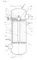
- FIG. 1is a longitudinal sectional view through a heat exchanger, on a reduced scale, according to the present invention.
- FIG. 2is a detail X of FIG. 1 as a longitudinal sectional view on an enlarged scale through an outlet end of a bypass tube of a heat exchanger according to the present invention with a control device arranged in the area of the outlet end.
- a heat exchanger 1is schematically shown in a longitudinal section in FIG. 1 in a vertical arrangement.
- the heat exchanger 1comprises a plurality of heat transfer tubes 3 and a centrally arranged bypass tube 4 , which are held each between a tube plate 5 of a gas inlet chamber 7 and a tube plate 6 of a gas outlet chamber 8 .
- the respective tube plates 5 , 6are connected to a cylindrical jacket 2 , within which a jacket space 9 is formed.
- the heat transfer tubes 3 and the bypass tube 4are enclosed in the jacket space 9 .
- a coolant 11flows through the jacket space 9 .
- the bypass tube 4is configured with a larger diameter than the heat transfer tubes 3 . Over a length of the bypass tube 4 , the bypass tube 4 has heat insulation 23 , on an inner tube wall 30 .
- the heat insulation 23is intended and configured for the bypass tube 4 not releasing essentially any heat while the process gas stream 14 is flowing through.
- the coolant 11flows into the jacket space 9 via at least one inlet pipe 10 arranged laterally at the cylindrical jacket 2 in the flow direction of the process gas stream 14 in front of the tube plate 6 of the gas outlet chamber 8 .
- the coolant 11leaves the jacket space 9 as a water/vapor mixture via at least one outlet pipe 12 arranged laterally on the cylindrical jacket 2 behind the tube plate 5 of the gas inlet chamber 7 .
- the water/vapor mixture formed during the coolingis generated by indirect heat transfer via the jacket side of the heat transfer tubes 3 .
- An inlet pipe 13 , 13 . 1is arranged in front of the tube plate 5 in the gas flow direction at the gas inlet chamber 7 laterally ( 13 ) or axially ( 13 . 1 —as is indicated by dotted line only).
- the process gas stream 14flows through the inlet pipes 13 , 13 . 1 into the gas inlet chamber 7 and from there into the ends of the heat transfer tubes 3 held in the tube plate 5 and into the end of the bypass tube 4 , as is indicated by arrows.
- a discharge pipe 15 , 15 . 1is arranged at the gas outlet chamber 8 laterally ( 15 ) or axially ( 15 . 1 ) behind the tube plate 6 in the gas flow direction.
- the process gas stream 14leaves the gas outlet chamber 8 , which is connected to the ends of the heat transfer tubes 3 being held in the tube plate 6 and to the other end of the bypass tube 4 , from which split process gas streams escape, as is indicated by arrows, through said discharge pipes 15 , 15 . 1 .
- a control device 16is arranged at the outlet end 17 of the bypass tube 4 .
- the control device 16comprises a throttle valve (valve body) 18 in a valve housing 22 and a drive 19 arranged outside the heat exchanger 1 .
- the drive 19is connected to a shaft 21 and double joints 20 and to an integrated shaft end 27 of the throttle valve 18 and forms a powertrain.
- the throttle valve 18is arranged adjustably with the connected double joints 20 and with the shaft end 27 by means of the drive 19 via the shaft 21 .
- the double jointsare intended essentially for compensating differences in thermal expansion between two bearings 25 for the respective integrated shaft end 27 of the throttle valve 18 in the valve housing 22 and a bearing 26 for the shaft 21 .
- the respective bearing 26is formed in a heat insulation 24 , which is applied to an inner wall 29 of the valve housing 22 .
- the bearing 26is arranged in a wall 28 of the gas outlet chamber 8 .
- the throttle valve (body) 18is arranged rotatably at right angles to the gas flow direction in the valve housing 22 .
- the heat insulation 24 applied to the inner wall 29 of the valve housing 22is preferably configured as a lining.
- the valve housing 22is configured as an extension of the bypass tube 4 with equal diameter if the existing installation conditions at the heat exchanger 1 are sufficient. In case of crowded installation conditions, a configuration of the valve housing 22 as is shown in FIG. 2 is to be preferred, and the extension of the bypass tube 4 over a conical attachment 31 is configured as a transition from the outlet end 17 of the bypass tube to an expanded diameter.
- the throttle valve 18 connected to the drive 19is provided for setting a gas outlet temperature of the heat exchanger 1 to a certain temperature range by mixing the cooled process gas stream 14 from the heat transfer tubes 3 with the uncooled process gas stream from the bypass tube 4 .
- a discharge speed (discharge rate) and a discharged quantity of the process gas stream 14can be controlled with the throttle valve 18 , which is arranged in the immediate vicinity of the outlet end 17 of the bypass tube 4 and adjustable by means of the drive 19 of the control device 16 .
- the throttle valve 18is made of a material resistant to high-temperature corrosion in the temperature range sensitive to high-temperature corrosion, which ranges from temperatures around 500° C. to an order of magnitude of about 850° C.
- the materials used as the control element for the throttle valve 18are high-temperature-resistant or metal-dusting-resistant materials that have temperature stability and do not require special cooling.
- the valve housing 22is manufactured from a material that is not necessarily fully resistant to high temperature corrosion, but is operated at a temperature outside of the range of high temperature corrosion. The valve housing 22 is protected by the insulation against high temperatures
- a ceramic materialwhich has high-temperature-resistant or metal-dusting-resistant properties with temperature stability, is used as a material for the throttle valve 18 —particularly, the throttle valve body—is comprised of ceramic material or especially consists of a ceramic material.
- Components made of other materialsare arranged heat insulated from the uncooled process gas stream 14 to the extent that these components can be used reliably according to the suitability of these materials.
Landscapes
- Engineering & Computer Science (AREA)
- General Engineering & Computer Science (AREA)
- Mechanical Engineering (AREA)
- Physics & Mathematics (AREA)
- Thermal Sciences (AREA)
- Chemical & Material Sciences (AREA)
- Combustion & Propulsion (AREA)
- Ceramic Engineering (AREA)
- Heat-Exchange Devices With Radiators And Conduit Assemblies (AREA)
- Exhaust Silencers (AREA)
Abstract
Description
- This application claims the benefit of priority under 35 U.S.C. §119 of
German Application 10 2015 013 517.1 filed Oct. 20, 2015, the entire contents of which are incorporated herein by reference. - The present invention pertains to a heat exchanger, which comprises within a cylindrical jacket a plurality of heat transfer tubes and a centrally arranged bypass tube, which are held each between a tube plate of a gas inlet chamber and a tube plate of a gas outlet chamber, wherein the tube plates are connected to a cylindrical jacket, which forms with the tube plates a jacket space, within which the heat transfer tubes and the bypass tube are enclosed and through which a coolant flows.
- Heat exchangers are used for various chemical and petrochemical processes. Heat transfer tubes are exposed to different gaseous and/or liquid media within the tubes and outside the tubes on the jacket side in such processes.
- As a rule, the hot process gas originating from a process is fed in such processes to the heat transfer tubes as well as to the bypass tube. During the hot process gas flow through the heat transfer tubes, the hot process gas releases heat via the respective tube jacket to a coolant, which is located in the jacket space.
- Water is usually used as the coolant. The process gas cooled by the heat transfer to the coolant subsequently flows out of the heat exchanger. It is often necessary to maintain the gas outlet temperature of the heat exchanger in a predefined temperature range.
- A usual bypass is usually used to set the gas outlet temperature. The gas outlet temperature is influenced at times with a control valve or rotary control valve or a control plug. Such control devices are arranged at the outlet end of the bypass tube. Such control devices are known from DE 28 46 455 B1 or EP 0 356 648 A1.
- The process gases in the bypass tube of a heat exchanger have a very high temperature. In most cases, such process gases also flow through the bypass tube at a high speed. A control device arranged at the outlet end of a bypass tube, for example, a control plug or a control valve, is therefore exposed to a very high load due to thermal effects.
EP 1 498 678 A1 discloses a heat exchanger with a bypass tube, which has a closing device as a formed piston—a piston configured as a closing device, which has a double-walled configuration and in which cooling ducts are formed in the double wall of the piston for the flow of a coolant. The coolant is fed to the cooling ducts in the double wall of the piston through a coolant line provided in a rod for actuating the piston.- DE 39 13 422 A1 discloses a tube bundle heat exchanger, which has a centrally arranged partial flow tube, which provides a control valve at the discharge-side end of the gas flow. The control valve has a double-walled configuration and is equipped in its interior space with ducts, through which a coolant can be passed, which is brought up through a valve shaft configured as a hollow shaft.
- DE 10 2005 057 674 B4 discloses a waste heat boiler, which comprises a control device, wherein the speed and the quantity of the gas stream being discharged in the bypass tube can be controlled by a plug, which is arranged at the outlet end of a bypass tube and is axially adjustable by means of the control device. The plug is cooled by a cooling medium, which flows through cooling ducts arranged in the plug.
- It proved to be disadvantageous in the prior-art control devices for a bypass tube for influencing the discharge temperature of a heat exchanger that such cooled pistons or control valves are susceptible to the temperature profiles becoming established, to failure of the cooling stream and thermal shock situations, so that leaks develop at such plugs and control valves. Thus, the prior-art control devices are no longer able to sufficiently accomplish the task of influencing the discharge temperature of a heat exchanger by such control devices for a bypass tube, so that the maintenance intervals will become undesirably short or the service life of a heat exchanger will become shorter.
- An object of the present invention is to provide a heat exchanger, which provides a reliable control device for controlling a certain process gas temperature, which control device satisfactorily withstands the high-temperature-related loads of a process gas stream without the use of a coolant for the control element and does not have such a complicated configuration.
- The basic object of the present invention is accomplished by providing a heat exchanger, which has the following advantages:
- The heat exchanger comprises a plurality of heat transfer tubes and a centrally arranged bypass tube, which are arranged each between a tube plate of a gas inlet chamber and a tube plate of a gas outlet chamber. The respective tube plates are connected to a cylindrical jacket, within which a jacket space is formed. The heat transfer tubes and the bypass tube are enclosed in the jacket space. A coolant flows through the jacket space. An inlet pipe is connected to the cylindrical jacket for introducing a coolant to the jacket side of the heat transfer tubes. Furthermore, an outlet pipe is connected to the cylindrical jacket for draining off water/vapor mixture generated through indirect heat transfer via the jacket side of the heat transfer tubes. An inlet pipe is arranged laterally or axially at the gas inlet chamber in the gas flow direction in front of the tube plate for introducing a hot process gas stream, into the heat transfer tubes and into the bypass tube on the gas inlet side of the tube plate. An outlet pipe is arranged laterally or axially at the gas outlet chamber in the gas flow direction behind the tube plate for draining off a mixture of cooled process gas stream from the heat transfer tubes and uncooled process gas stream from the bypass tube on the gas outlet side of the tube plate. A control device, which is arranged in the immediate vicinity at the outlet end of the bypass tube and which comprises a throttle valve connected to a drive for setting a gas outlet temperature of the heat exchanger to a certain temperature range. A certain discharge speed (discharge rate) and discharged quantity of the process gas stream from the bypass tube can be controlled by the throttle valve, which is arranged at the outlet end of the bypass tube and is adjustable by means of the drive of the control device.
- The throttle valve advantageously consists of a material resistant to high-temperature corrosion in the temperature range sensitive to high-temperature corrosion.
- The throttle valve of the control device is advantageously arranged adjustably, by means of the drive, via double joints.
- The throttle valve of the control device is preferably connected to the drive via a shaft and the double joints.
- The throttle valve is advantageously arranged on both sides with an integrated shaft end or shaft attachment in a bearing formed in a heat insulation applied at the inner wall of the valve housing and the shaft is arranged in a bearing in the wall of the gas outlet chamber, the double joints connected to the drive via the shaft end and the shaft being provided for compensating differences in expansion between the bearing of the respective shaft end of the throttle valve in the valve housing and the bearing of the shaft in the wall of the gas outlet chamber.
- The throttle valve comprises a valve body that is arranged rotatably in the valve housing at right angles to the gas flow direction. The valve housing is advantageously configured as an extension of the bypass tube with the same diameter or with an expanded diameter with a conical attachment as a transition from the outlet end of the bypass tube to the expanded diameter.
- A ceramic material is preferably used as a high-temperature-resistant or metal-dusting-resistant material for the throttle valve, particularly for the valve body.
- Based on the advantageous embodiment of a heat exchanger with a control device for adjusting the gas outlet temperature of a cooled process gas stream to the required temperature conditions in a certain temperature range by means of the uncooled process gas stream from the bypass tube, reliable influencing of the temperature is provided, which operates independently from a satisfactory coolant feed and the efficiency of the cooling for the control elements used and of the sealing of the coolant lines. High-temperature-resistant or metal-dusting-resistant materials, which do not require special cooling, are used for the control element in the present invention. Components made of other materials are arranged such that they are heat insulated from the uncooled process gas stream to the extent that these components can reliably be used according to the suitability of these materials.
- An exemplary embodiment of the present invention will be explained in more detail below in the description on the basis of a heat exchanger shown in the drawings. The various features of novelty which characterize the invention are pointed out with particularity in the claims annexed to and forming a part of this disclosure. For a better understanding of the invention, its operating advantages and specific objects attained by its uses, reference is made to the accompanying drawings and descriptive matter in which preferred embodiments of the invention are illustrated.
- In the drawings:
FIG. 1 is a longitudinal sectional view through a heat exchanger, on a reduced scale, according to the present invention; andFIG. 2 is a detail X ofFIG. 1 as a longitudinal sectional view on an enlarged scale through an outlet end of a bypass tube of a heat exchanger according to the present invention with a control device arranged in the area of the outlet end.- Referring to the drawings, a
heat exchanger 1 is schematically shown in a longitudinal section inFIG. 1 in a vertical arrangement.Such heat exchangers 1 are used for various chemical and petrochemical processes. Theheat exchanger 1 comprises a plurality ofheat transfer tubes 3 and a centrally arrangedbypass tube 4, which are held each between atube plate 5 of agas inlet chamber 7 and atube plate 6 of agas outlet chamber 8. Therespective tube plates cylindrical jacket 2, within which ajacket space 9 is formed. Theheat transfer tubes 3 and thebypass tube 4 are enclosed in thejacket space 9. Acoolant 11 flows through thejacket space 9. - The
bypass tube 4 is configured with a larger diameter than theheat transfer tubes 3. Over a length of thebypass tube 4, thebypass tube 4 hasheat insulation 23, on aninner tube wall 30. Theheat insulation 23 is intended and configured for thebypass tube 4 not releasing essentially any heat while theprocess gas stream 14 is flowing through. - As is indicated by an arrow, the
coolant 11 flows into thejacket space 9 via at least oneinlet pipe 10 arranged laterally at thecylindrical jacket 2 in the flow direction of theprocess gas stream 14 in front of thetube plate 6 of thegas outlet chamber 8. Thecoolant 11 leaves thejacket space 9 as a water/vapor mixture via at least oneoutlet pipe 12 arranged laterally on thecylindrical jacket 2 behind thetube plate 5 of thegas inlet chamber 7. The water/vapor mixture formed during the cooling is generated by indirect heat transfer via the jacket side of theheat transfer tubes 3. - An
inlet pipe 13,13.1 is arranged in front of thetube plate 5 in the gas flow direction at thegas inlet chamber 7 laterally (13) or axially (13.1—as is indicated by dotted line only). As is indicated by an arrow, theprocess gas stream 14 flows through theinlet pipes 13,13.1 into thegas inlet chamber 7 and from there into the ends of theheat transfer tubes 3 held in thetube plate 5 and into the end of thebypass tube 4, as is indicated by arrows. - Indicated by dotted line only, a
discharge pipe 15,15.1 is arranged at thegas outlet chamber 8 laterally (15) or axially (15.1) behind thetube plate 6 in the gas flow direction. As is indicated by an arrow, theprocess gas stream 14 leaves thegas outlet chamber 8, which is connected to the ends of theheat transfer tubes 3 being held in thetube plate 6 and to the other end of thebypass tube 4, from which split process gas streams escape, as is indicated by arrows, through saiddischarge pipes 15,15.1. - A
control device 16 is arranged at the outlet end17 of thebypass tube 4. Thecontrol device 16 comprises a throttle valve (valve body)18 in avalve housing 22 and adrive 19 arranged outside theheat exchanger 1. Thedrive 19 is connected to ashaft 21 anddouble joints 20 and to anintegrated shaft end 27 of thethrottle valve 18 and forms a powertrain. Thethrottle valve 18 is arranged adjustably with the connecteddouble joints 20 and with theshaft end 27 by means of thedrive 19 via theshaft 21. - The double joints are intended essentially for compensating differences in thermal expansion between two
bearings 25 for the respectiveintegrated shaft end 27 of thethrottle valve 18 in thevalve housing 22 and abearing 26 for theshaft 21. Therespective bearing 26 is formed in aheat insulation 24, which is applied to aninner wall 29 of thevalve housing 22. Thebearing 26 is arranged in awall 28 of thegas outlet chamber 8. - The throttle valve (body)18 is arranged rotatably at right angles to the gas flow direction in the
valve housing 22. Theheat insulation 24 applied to theinner wall 29 of thevalve housing 22 is preferably configured as a lining. - The
valve housing 22 is configured as an extension of thebypass tube 4 with equal diameter if the existing installation conditions at theheat exchanger 1 are sufficient. In case of crowded installation conditions, a configuration of thevalve housing 22 as is shown inFIG. 2 is to be preferred, and the extension of thebypass tube 4 over aconical attachment 31 is configured as a transition from the outlet end17 of the bypass tube to an expanded diameter. - The
throttle valve 18 connected to thedrive 19 is provided for setting a gas outlet temperature of theheat exchanger 1 to a certain temperature range by mixing the cooledprocess gas stream 14 from theheat transfer tubes 3 with the uncooled process gas stream from thebypass tube 4. A discharge speed (discharge rate) and a discharged quantity of theprocess gas stream 14 can be controlled with thethrottle valve 18, which is arranged in the immediate vicinity of the outlet end17 of thebypass tube 4 and adjustable by means of thedrive 19 of thecontrol device 16. - The
throttle valve 18 is made of a material resistant to high-temperature corrosion in the temperature range sensitive to high-temperature corrosion, which ranges from temperatures around 500° C. to an order of magnitude of about 850° C. The materials used as the control element for thethrottle valve 18 are high-temperature-resistant or metal-dusting-resistant materials that have temperature stability and do not require special cooling. Thevalve housing 22 is manufactured from a material that is not necessarily fully resistant to high temperature corrosion, but is operated at a temperature outside of the range of high temperature corrosion. Thevalve housing 22 is protected by the insulation against high temperatures - A ceramic material, which has high-temperature-resistant or metal-dusting-resistant properties with temperature stability, is used as a material for the
throttle valve 18—particularly, the throttle valve body—is comprised of ceramic material or especially consists of a ceramic material. - Components made of other materials are arranged heat insulated from the uncooled
process gas stream 14 to the extent that these components can be used reliably according to the suitability of these materials. - While specific embodiments of the invention have been shown and described in detail to illustrate the application of the principles of the invention, it will be understood that the invention may be embodied otherwise without departing from such principles.
List of Reference Numbers 1 Heat exchanger 2 Cylindrical jacket 3 Heat transfer tubes 4 Bypass tube 5 Tube plate on the process gas stream inlet side 6 Tube plate on the process gas stream outlet side 7 Gas inlet chamber 8 Gas outlet chamber 9 Jacket space 10 Inlet pipe 11 Coolant 12 Outlet pipe 13 Inlet pipe 14 Process gas stream 15 Discharge pipe 16 Control device 17 Outlet end of the bypass tube 18 Throttle valve 19 Drive 20 Double joints 21 Shaft 22 Valve housing 23 Heat insulation of the bypass tube 24 Heat insulation of the valve housing 25 Bearing of the shaft end of the throttle valve 26 Bearing of the shaft 27 Shaft end 28 Wall of the gas outlet chamber 29 Inner wall of the valve housing 30 Inner wall of the bypass tube 31 Conical attachment
Claims (19)
Applications Claiming Priority (2)
| Application Number | Priority Date | Filing Date | Title |
|---|---|---|---|
| DE102015013517.1 | 2015-10-20 | ||
| DE102015013517.1ADE102015013517A1 (en) | 2015-10-20 | 2015-10-20 | Heat exchanger |
Publications (2)
| Publication Number | Publication Date |
|---|---|
| US20170108282A1true US20170108282A1 (en) | 2017-04-20 |
| US11226159B2 US11226159B2 (en) | 2022-01-18 |
Family
ID=57103761
Family Applications (1)
| Application Number | Title | Priority Date | Filing Date |
|---|---|---|---|
| US15/297,486Active2039-02-01US11226159B2 (en) | 2015-10-20 | 2016-10-19 | Heat exchanger |
Country Status (12)
| Country | Link |
|---|---|
| US (1) | US11226159B2 (en) |
| EP (1) | EP3159646B2 (en) |
| JP (1) | JP2017078567A (en) |
| KR (1) | KR20170046090A (en) |
| CN (1) | CN106595353A (en) |
| BR (1) | BR102016024429A2 (en) |
| CA (1) | CA2943963A1 (en) |
| DE (1) | DE102015013517A1 (en) |
| ES (1) | ES2721310T3 (en) |
| HU (1) | HUE043660T2 (en) |
| PL (1) | PL3159646T3 (en) |
| TR (1) | TR201903875T4 (en) |
Cited By (2)
| Publication number | Priority date | Publication date | Assignee | Title |
|---|---|---|---|---|
| CN117597562A (en)* | 2021-06-08 | 2024-02-23 | 巴塞尔聚烯烃股份有限公司 | Heat exchanger for gas phase polymerization |
| US12429295B2 (en) | 2022-11-10 | 2025-09-30 | L'air Liquide, Societe Anonyme Pour L'etude Et L'exploitation Des Procedes Georges Claude | Control device for controlling the temperature of a process gas and heat exchanger having a control device |
Families Citing this family (4)
| Publication number | Priority date | Publication date | Assignee | Title |
|---|---|---|---|---|
| CN108562075B (en)* | 2018-02-06 | 2024-02-06 | 北京华创瑞风空调科技有限公司 | Knockout and have its heat exchanger |
| WO2021078444A1 (en) | 2019-10-25 | 2021-04-29 | Casale Sa | Process and reactor for catalytic oxidation of ammonia |
| DE102021107639A1 (en) | 2021-03-26 | 2022-09-29 | Mann+Hummel Gmbh | Water separator with a throttling element, use of a water separator and fuel cell system with a water separator |
| CN113756931B (en)* | 2021-08-19 | 2022-11-22 | 潍柴重机股份有限公司 | Marine heat exchanger, heat exchange system and heat exchange control method |
Citations (13)
| Publication number | Priority date | Publication date | Assignee | Title |
|---|---|---|---|---|
| US447285A (en)* | 1891-03-03 | albergee | ||
| US1918966A (en)* | 1930-06-20 | 1933-07-18 | Gen Chemical Corp | Apparatus for treating gas |
| US3477411A (en)* | 1967-12-22 | 1969-11-11 | Aqua Chem Inc | Heat recovery boiler with bypass |
| US4993367A (en)* | 1988-08-18 | 1991-02-19 | Borsig Gmbh | Heat exchanger |
| US5452686A (en)* | 1993-03-26 | 1995-09-26 | Haldor Topsoe A/S | Waste heat boiler |
| US5852990A (en)* | 1994-06-29 | 1998-12-29 | Haldor Topsoe A/S | Waste heat boiler |
| US6148909A (en)* | 1998-01-27 | 2000-11-21 | Komatsu Ltd. | Temperature control device and temperature control method |
| US7232000B2 (en)* | 2001-10-05 | 2007-06-19 | Gkn Driveline International Gmbh | Drive-steer axle for motor-driven vehicles |
| US7412945B2 (en)* | 2005-12-01 | 2008-08-19 | Alstom Technology Ltd. | Waste heat boiler |
| US20080244975A1 (en)* | 2002-01-04 | 2008-10-09 | Johnston Anthony M | Reforming apparatus and method |
| US20090065185A1 (en)* | 2006-01-23 | 2009-03-12 | Alstom Technology Ltd. | Tube Bundle Heat Exchanger |
| US20110059335A1 (en)* | 2003-08-28 | 2011-03-10 | Johan Hernblom | Composite Tube |
| WO2011089140A1 (en)* | 2010-01-21 | 2011-07-28 | Shell Internationale Research Maatschappij B.V. | Heat exchanger and method of operating a heat exchanger |
Family Cites Families (20)
| Publication number | Priority date | Publication date | Assignee | Title |
|---|---|---|---|---|
| CA767520A (en)† | 1967-09-19 | A. Mccallister Robert | Heat exchanger control scheme | |
| US3199577A (en)† | 1962-06-14 | 1965-08-10 | Foster Wheeler Corp | Heat exchanger control scheme |
| DE2846455C2 (en) | 1978-10-23 | 1980-07-31 | Borsig Gmbh, 1000 Berlin | Shell and tube heat exchanger with a constant outlet temperature of one of the two media |
| DE8504717U1 (en)* | 1985-02-20 | 1985-05-30 | Hermann Rappold & Co GmbH, 5160 Düren | MULTI-BLADE FLAP FOR HOT GASES |
| DE3583503D1 (en)† | 1985-04-30 | 1991-08-22 | Asahi Glass Co Ltd | THROTTLE VALVE FOR CONTROLLING A HIGH TEMPERATURE FLUID. |
| DE3913422C3 (en)† | 1989-04-24 | 1994-04-14 | Steinmueller Gmbh L & C | Shell and tube heat exchangers |
| ATE391844T1 (en)† | 2000-12-19 | 2008-04-15 | Valeo Termico Sa | HEAT EXCHANGER MODULE PARTICULARLY DESIGNED FOR AN EXHAUST GAS RECIRCULATION SYSTEM |
| ES2174739B1 (en)† | 2000-12-19 | 2003-11-01 | Valeo Termico Sa | HEAT EXCHANGER MODULE FOR AN EXHAUST GAS RECIRCULATION SYSTEM. |
| US20050133202A1 (en)† | 2001-11-09 | 2005-06-23 | Aalborg Industries A/S | Heat exchanger, combination with heat exchanger and method of manufacturing the heat exchanger |
| ATE338931T1 (en) | 2003-07-12 | 2006-09-15 | Borsig Gmbh | HEAT EXCHANGER WITH A BYPASS TUBE |
| US7412845B2 (en)* | 2004-11-15 | 2008-08-19 | Sunbeam Products, Inc. | Ice cream maker including nestable canister assembly |
| US8480054B2 (en)* | 2008-05-30 | 2013-07-09 | Woodward, Inc. | Tortionally stiff, thermally isolating shaft coupling with multiple degrees of freedom to accommodate misalignment |
| DE102009048592A1 (en)* | 2009-10-07 | 2011-04-14 | Lurgi Gmbh | Waste heat recovery boiler has multiple heat transfer tubes and bypass tube inside cylindrical outer cover, where heat transfer tubes and bypass tube have inlet end and outlet end |
| EP2312252B1 (en)* | 2009-10-07 | 2013-03-20 | Lurgi GmbH | Waste heat boiler and method for cooling synthesis gas |
| WO2012041344A1 (en)* | 2010-09-30 | 2012-04-05 | Haldor Topsoe A/S | Waste heat boiler |
| DE102012007721B4 (en)† | 2012-04-19 | 2022-02-24 | Thyssenkrupp Industrial Solutions Ag | Process gas cooler with lever-controlled process gas cooler flaps |
| CN203395204U (en)† | 2013-07-30 | 2014-01-15 | 温州东特蝶阀有限公司 | Novel ceramic butterfly valve |
| CN103471432B (en)† | 2013-09-26 | 2015-11-18 | 上海锅炉厂有限公司 | One has the board-like fixed tube-sheet exchanger of temperature controlling function double helix |
| CN203586173U (en)† | 2013-10-29 | 2014-05-07 | 内蒙古大唐国际克什克腾煤制天然气有限责任公司 | Waste heat boiler |
| CN203758309U (en)* | 2014-03-12 | 2014-08-06 | 中国科学院广州能源研究所 | Direct-turbulent flow oil cooler with variable pipe and shell side space |
- 2015
- 2015-10-20DEDE102015013517.1Apatent/DE102015013517A1/ennot_activeWithdrawn
- 2016
- 2016-09-30HUHUE16002142Apatent/HUE043660T2/enunknown
- 2016-09-30EPEP16002142.4Apatent/EP3159646B2/ennot_activeNot-in-force
- 2016-09-30PLPL16002142Tpatent/PL3159646T3/enunknown
- 2016-09-30CACA2943963Apatent/CA2943963A1/ennot_activeAbandoned
- 2016-09-30TRTR2019/03875Tpatent/TR201903875T4/enunknown
- 2016-09-30ESES16002142Tpatent/ES2721310T3/enactiveActive
- 2016-10-18CNCN201610907503.6Apatent/CN106595353A/enactivePending
- 2016-10-18JPJP2016204614Apatent/JP2017078567A/enactivePending
- 2016-10-19KRKR1020160135487Apatent/KR20170046090A/ennot_activeWithdrawn
- 2016-10-19BRBR102016024429-3Apatent/BR102016024429A2/enactiveSearch and Examination
- 2016-10-19USUS15/297,486patent/US11226159B2/enactiveActive
Patent Citations (14)
| Publication number | Priority date | Publication date | Assignee | Title |
|---|---|---|---|---|
| US447285A (en)* | 1891-03-03 | albergee | ||
| US1918966A (en)* | 1930-06-20 | 1933-07-18 | Gen Chemical Corp | Apparatus for treating gas |
| US3477411A (en)* | 1967-12-22 | 1969-11-11 | Aqua Chem Inc | Heat recovery boiler with bypass |
| US4993367A (en)* | 1988-08-18 | 1991-02-19 | Borsig Gmbh | Heat exchanger |
| US5452686A (en)* | 1993-03-26 | 1995-09-26 | Haldor Topsoe A/S | Waste heat boiler |
| US5852990A (en)* | 1994-06-29 | 1998-12-29 | Haldor Topsoe A/S | Waste heat boiler |
| US6148909A (en)* | 1998-01-27 | 2000-11-21 | Komatsu Ltd. | Temperature control device and temperature control method |
| US7232000B2 (en)* | 2001-10-05 | 2007-06-19 | Gkn Driveline International Gmbh | Drive-steer axle for motor-driven vehicles |
| US20080244975A1 (en)* | 2002-01-04 | 2008-10-09 | Johnston Anthony M | Reforming apparatus and method |
| US20110059335A1 (en)* | 2003-08-28 | 2011-03-10 | Johan Hernblom | Composite Tube |
| US7412945B2 (en)* | 2005-12-01 | 2008-08-19 | Alstom Technology Ltd. | Waste heat boiler |
| US20090065185A1 (en)* | 2006-01-23 | 2009-03-12 | Alstom Technology Ltd. | Tube Bundle Heat Exchanger |
| WO2011089140A1 (en)* | 2010-01-21 | 2011-07-28 | Shell Internationale Research Maatschappij B.V. | Heat exchanger and method of operating a heat exchanger |
| US20120305847A1 (en)* | 2010-01-21 | 2012-12-06 | Thomas Paul Von Kossak-Glowczewski | Heat exchanger and method of operating a heat exchanger |
Cited By (2)
| Publication number | Priority date | Publication date | Assignee | Title |
|---|---|---|---|---|
| CN117597562A (en)* | 2021-06-08 | 2024-02-23 | 巴塞尔聚烯烃股份有限公司 | Heat exchanger for gas phase polymerization |
| US12429295B2 (en) | 2022-11-10 | 2025-09-30 | L'air Liquide, Societe Anonyme Pour L'etude Et L'exploitation Des Procedes Georges Claude | Control device for controlling the temperature of a process gas and heat exchanger having a control device |
Also Published As
| Publication number | Publication date |
|---|---|
| DE102015013517A1 (en) | 2017-04-20 |
| US11226159B2 (en) | 2022-01-18 |
| EP3159646A1 (en) | 2017-04-26 |
| PL3159646T3 (en) | 2019-07-31 |
| CN106595353A (en) | 2017-04-26 |
| EP3159646B2 (en) | 2021-12-29 |
| CA2943963A1 (en) | 2017-04-20 |
| TR201903875T4 (en) | 2019-04-22 |
| KR20170046090A (en) | 2017-04-28 |
| JP2017078567A (en) | 2017-04-27 |
| ES2721310T3 (en) | 2019-07-30 |
| BR102016024429A2 (en) | 2017-10-10 |
| EP3159646B1 (en) | 2019-03-06 |
| HUE043660T2 (en) | 2019-08-28 |
Similar Documents
| Publication | Publication Date | Title |
|---|---|---|
| US11226159B2 (en) | Heat exchanger | |
| US4850857A (en) | Apparatus for the combustion of oxidizable substances suspended in a carrier gas | |
| US10006719B2 (en) | Tube bundle heat exchanger having straight-tube configuration, process gas cooler, cooler for gas turbine cooling air, gas turbine or gas and steam turbine power plant, and method for the cooling of cooling air | |
| DK1793189T3 (en) | Waste heat boiler | |
| SE454992B (en) | SYNTHESIA RINSEER AND EXHAUST RANGE | |
| KR100209115B1 (en) | Steam generator | |
| KR20200011480A (en) | Cylindrical Manifold Equipment with Bypass | |
| CN107427787B (en) | Waste heat boiler system, mixing chamber and method for cooling process gas | |
| JP5322142B2 (en) | 2-tower exhaust heat recovery system | |
| RU2443959C2 (en) | Multiple-bed furnace | |
| US10281224B2 (en) | Heat exchanger | |
| US3628508A (en) | Waste-heat boilers and like gas/liquid heat transfer systems | |
| US20030075304A1 (en) | Heat-exchange system | |
| US8103156B2 (en) | Fuel gas conditioning system | |
| CS209534B2 (en) | Elbow for exhausting the gas waste products | |
| RU2453783C2 (en) | Multiple-bedded furnace | |
| CN114144633B (en) | Tube bundle heat exchanger | |
| US20130299134A1 (en) | Thermal expansion joint and heat exchanger | |
| CN209958151U (en) | Insulation arrangement for a drying cylinder of a web forming machine and drying cylinder of a web forming machine | |
| CZ17603U1 (en) | Reversible explosion-proof safety, particularly for pipe systems | |
| SE510235C2 (en) | Ways and boilers for optimized combustion | |
| CZ2007313A3 (en) | Reversible explosion-proof safety, particularly for pipe systems | |
| PL61101B1 (en) |
Legal Events
| Date | Code | Title | Description |
|---|---|---|---|
| AS | Assignment | Owner name:BORSIG GMBH, GERMANY Free format text:ASSIGNMENT OF ASSIGNORS INTEREST;ASSIGNOR:MUEGGENBURG, JAN;REEL/FRAME:040063/0038 Effective date:20160926 | |
| STCV | Information on status: appeal procedure | Free format text:APPEAL BRIEF (OR SUPPLEMENTAL BRIEF) ENTERED AND FORWARDED TO EXAMINER | |
| STPP | Information on status: patent application and granting procedure in general | Free format text:NON FINAL ACTION MAILED | |
| STPP | Information on status: patent application and granting procedure in general | Free format text:RESPONSE TO NON-FINAL OFFICE ACTION ENTERED AND FORWARDED TO EXAMINER | |
| STPP | Information on status: patent application and granting procedure in general | Free format text:FINAL REJECTION MAILED | |
| STCV | Information on status: appeal procedure | Free format text:NOTICE OF APPEAL FILED | |
| STCV | Information on status: appeal procedure | Free format text:APPEAL BRIEF (OR SUPPLEMENTAL BRIEF) ENTERED AND FORWARDED TO EXAMINER | |
| STCV | Information on status: appeal procedure | Free format text:ON APPEAL -- AWAITING DECISION BY THE BOARD OF APPEALS | |
| STCV | Information on status: appeal procedure | Free format text:BOARD OF APPEALS DECISION RENDERED | |
| STPP | Information on status: patent application and granting procedure in general | Free format text:NOTICE OF ALLOWANCE MAILED -- APPLICATION RECEIVED IN OFFICE OF PUBLICATIONS | |
| STPP | Information on status: patent application and granting procedure in general | Free format text:PUBLICATIONS -- ISSUE FEE PAYMENT RECEIVED | |
| STPP | Information on status: patent application and granting procedure in general | Free format text:PUBLICATIONS -- ISSUE FEE PAYMENT VERIFIED | |
| STCF | Information on status: patent grant | Free format text:PATENTED CASE | |
| FEPP | Fee payment procedure | Free format text:MAINTENANCE FEE REMINDER MAILED (ORIGINAL EVENT CODE: REM.); ENTITY STATUS OF PATENT OWNER: LARGE ENTITY |