US20160138807A1 - Gas Turbine Engine Flow Regulating - Google Patents
Gas Turbine Engine Flow RegulatingDownload PDFInfo
- Publication number
- US20160138807A1 US20160138807A1US14/899,982US201314899982AUS2016138807A1US 20160138807 A1US20160138807 A1US 20160138807A1US 201314899982 AUS201314899982 AUS 201314899982AUS 2016138807 A1US2016138807 A1US 2016138807A1
- Authority
- US
- United States
- Prior art keywords
- dome
- sleeve
- stator
- fuel injector
- inlet opening
- Prior art date
- Legal status (The legal status is an assumption and is not a legal conclusion. Google has not performed a legal analysis and makes no representation as to the accuracy of the status listed.)
- Granted
Links
- 230000001105regulatory effectEffects0.000titledescription3
- 239000000446fuelSubstances0.000claimsabstractdescription135
- 238000000034methodMethods0.000claimsdescription8
- 230000033001locomotionEffects0.000claimsdescription7
- 210000001145finger jointAnatomy0.000claimsdescription5
- 230000008878couplingEffects0.000claims2
- 238000010168coupling processMethods0.000claims2
- 238000005859coupling reactionMethods0.000claims2
- 239000003570airSubstances0.000description41
- 239000007789gasSubstances0.000description34
- 238000002485combustion reactionMethods0.000description19
- 239000007788liquidSubstances0.000description14
- 239000000203mixtureSubstances0.000description7
- 230000007423decreaseEffects0.000description4
- 239000012080ambient airSubstances0.000description3
- 230000000712assemblyEffects0.000description3
- 238000000429assemblyMethods0.000description3
- 230000003993interactionEffects0.000description3
- 238000010008shearingMethods0.000description3
- 238000011144upstream manufacturingMethods0.000description3
- IJGRMHOSHXDMSA-UHFFFAOYSA-NAtomic nitrogenChemical compoundN#NIJGRMHOSHXDMSA-UHFFFAOYSA-N0.000description2
- 239000004215Carbon black (E152)Substances0.000description2
- 230000000295complement effectEffects0.000description2
- 230000003247decreasing effectEffects0.000description2
- 229930195733hydrocarbonNatural products0.000description2
- 150000002430hydrocarbonsChemical class0.000description2
- 230000008901benefitEffects0.000description1
- 230000033228biological regulationEffects0.000description1
- 238000004891communicationMethods0.000description1
- 230000001276controlling effectEffects0.000description1
- 208000002925dental cariesDiseases0.000description1
- 239000000284extractSubstances0.000description1
- 239000010408filmSubstances0.000description1
- 239000012530fluidSubstances0.000description1
- 238000002347injectionMethods0.000description1
- 239000007924injectionSubstances0.000description1
- 238000004519manufacturing processMethods0.000description1
- 239000003595mistSubstances0.000description1
- 238000012986modificationMethods0.000description1
- 230000004048modificationEffects0.000description1
- 229910052757nitrogenInorganic materials0.000description1
- 230000009467reductionEffects0.000description1
- 230000007480spreadingEffects0.000description1
- 230000006641stabilisationEffects0.000description1
- 238000011105stabilizationMethods0.000description1
- 230000008646thermal stressEffects0.000description1
- 239000010409thin filmSubstances0.000description1
Images


Classifications
- F—MECHANICAL ENGINEERING; LIGHTING; HEATING; WEAPONS; BLASTING
- F23—COMBUSTION APPARATUS; COMBUSTION PROCESSES
- F23R—GENERATING COMBUSTION PRODUCTS OF HIGH PRESSURE OR HIGH VELOCITY, e.g. GAS-TURBINE COMBUSTION CHAMBERS
- F23R3/00—Continuous combustion chambers using liquid or gaseous fuel
- F23R3/02—Continuous combustion chambers using liquid or gaseous fuel characterised by the air-flow or gas-flow configuration
- F23R3/04—Air inlet arrangements
- F23R3/10—Air inlet arrangements for primary air
- F23R3/12—Air inlet arrangements for primary air inducing a vortex
- F23R3/14—Air inlet arrangements for primary air inducing a vortex by using swirl vanes
- F—MECHANICAL ENGINEERING; LIGHTING; HEATING; WEAPONS; BLASTING
- F23—COMBUSTION APPARATUS; COMBUSTION PROCESSES
- F23C—METHODS OR APPARATUS FOR COMBUSTION USING FLUID FUEL OR SOLID FUEL SUSPENDED IN A CARRIER GAS OR AIR
- F23C7/00—Combustion apparatus characterised by arrangements for air supply
- F23C7/008—Flow control devices
- F—MECHANICAL ENGINEERING; LIGHTING; HEATING; WEAPONS; BLASTING
- F23—COMBUSTION APPARATUS; COMBUSTION PROCESSES
- F23R—GENERATING COMBUSTION PRODUCTS OF HIGH PRESSURE OR HIGH VELOCITY, e.g. GAS-TURBINE COMBUSTION CHAMBERS
- F23R3/00—Continuous combustion chambers using liquid or gaseous fuel
- F23R3/02—Continuous combustion chambers using liquid or gaseous fuel characterised by the air-flow or gas-flow configuration
- F23R3/04—Air inlet arrangements
- F23R3/10—Air inlet arrangements for primary air
- F—MECHANICAL ENGINEERING; LIGHTING; HEATING; WEAPONS; BLASTING
- F23—COMBUSTION APPARATUS; COMBUSTION PROCESSES
- F23R—GENERATING COMBUSTION PRODUCTS OF HIGH PRESSURE OR HIGH VELOCITY, e.g. GAS-TURBINE COMBUSTION CHAMBERS
- F23R3/00—Continuous combustion chambers using liquid or gaseous fuel
- F23R3/02—Continuous combustion chambers using liquid or gaseous fuel characterised by the air-flow or gas-flow configuration
- F23R3/26—Controlling the air flow
- F—MECHANICAL ENGINEERING; LIGHTING; HEATING; WEAPONS; BLASTING
- F23—COMBUSTION APPARATUS; COMBUSTION PROCESSES
- F23R—GENERATING COMBUSTION PRODUCTS OF HIGH PRESSURE OR HIGH VELOCITY, e.g. GAS-TURBINE COMBUSTION CHAMBERS
- F23R3/00—Continuous combustion chambers using liquid or gaseous fuel
- F23R3/28—Continuous combustion chambers using liquid or gaseous fuel characterised by the fuel supply
- F23R3/286—Continuous combustion chambers using liquid or gaseous fuel characterised by the fuel supply having fuel-air premixing devices
- F—MECHANICAL ENGINEERING; LIGHTING; HEATING; WEAPONS; BLASTING
- F23—COMBUSTION APPARATUS; COMBUSTION PROCESSES
- F23R—GENERATING COMBUSTION PRODUCTS OF HIGH PRESSURE OR HIGH VELOCITY, e.g. GAS-TURBINE COMBUSTION CHAMBERS
- F23R3/00—Continuous combustion chambers using liquid or gaseous fuel
- F23R3/28—Continuous combustion chambers using liquid or gaseous fuel characterised by the fuel supply
- F23R3/36—Supply of different fuels
- F—MECHANICAL ENGINEERING; LIGHTING; HEATING; WEAPONS; BLASTING
- F23—COMBUSTION APPARATUS; COMBUSTION PROCESSES
- F23D—BURNERS
- F23D2900/00—Special features of, or arrangements for burners using fluid fuels or solid fuels suspended in a carrier gas
- F23D2900/11101—Pulverising gas flow impinging on fuel from pre-filming surface, e.g. lip atomizers
- F—MECHANICAL ENGINEERING; LIGHTING; HEATING; WEAPONS; BLASTING
- F23—COMBUSTION APPARATUS; COMBUSTION PROCESSES
- F23D—BURNERS
- F23D2900/00—Special features of, or arrangements for burners using fluid fuels or solid fuels suspended in a carrier gas
- F23D2900/11402—Airflow diaphragms at burner nozzle
- Y—GENERAL TAGGING OF NEW TECHNOLOGICAL DEVELOPMENTS; GENERAL TAGGING OF CROSS-SECTIONAL TECHNOLOGIES SPANNING OVER SEVERAL SECTIONS OF THE IPC; TECHNICAL SUBJECTS COVERED BY FORMER USPC CROSS-REFERENCE ART COLLECTIONS [XRACs] AND DIGESTS
- Y02—TECHNOLOGIES OR APPLICATIONS FOR MITIGATION OR ADAPTATION AGAINST CLIMATE CHANGE
- Y02T—CLIMATE CHANGE MITIGATION TECHNOLOGIES RELATED TO TRANSPORTATION
- Y02T50/00—Aeronautics or air transport
- Y02T50/60—Efficient propulsion technologies, e.g. for aircraft
Definitions
- This specificationgenerally relates to combustor assemblies for gas turbine engines.
- the gas turbine engineis the preferred class of internal combustion engine for many high power applications. Fundamentally, the gas turbine engine features an upstream rotating compressor coupled to a downstream turbine, and a combustion chamber in-between.
- One of the driving factors in modern gas turbine engine designis emissions reduction, and the combustor is the primary contributor in this regard.
- Combustion of the hydrocarbon fuel in airinevitably produces harmful emissions, such as oxides of nitrogen (NOx). NOx emissions are the subject of increasingly stringent controls by regulatory authorities. NOx emissions scale with the temperature of the combustion flame. The combustion flame temperature is product of several factors, including the fuel-air ratio. A lean fuel-air ratio is likely to produce less NOx emissions, but can cause problems in maintaining the stability of the combustion flame. Thus, new concepts are continuously sought to achieve low NOx emissions with a stable combustion flame.
- FIG. 1is a half, side cross-sectional view of an example gas turbine engine.
- FIG. 2is a perspective view of a triple-dome annular gas turbine combustor assembly.
- FIG. 3Ais a cross-sectional view, taken along the line 3 - 3 , of the gas turbine combustor assembly shown in FIG. 2 .
- FIG. 3Bis a half, side cross-sectional view of a fuel injector of the gas turbine combustor assembly shown in FIG. 2 .
- FIGS. 4A and 4Bare front and rear perspective views of a dome stator of the gas turbine combustor assembly shown in FIG. 2 .
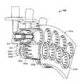
- FIGS. 5A and 5Bare front and rear perspective views of the center dome sleeve of the gas turbine combustor assembly shown in FIG. 2 .
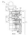
- FIG. 5Cis a half, cross-sectional view of the center dome sleeve of the gas turbine combustor assembly shown in FIG. 2 positioned relative to a fuel injector.
- FIG. 6is a top view of the center dome sleeve of the gas turbine combustor assembly shown in FIG. 2 coupled with corresponding dome stators.
- FIG. 7is a half, side cross-sectional view of a dome sleeve featuring a nozzle opening with a flared outlet positioned relative to a fuel injector having a diverging-nozzle outlet.
- FIG. 8is a half, perspective cross-sectional view of a dual-dome annular gas turbine combustor assembly.
- FIG. 9Ais a perspective view of a can-type gas turbine combustor assembly.
- FIG. 9Bis a half, perspective cross-sectional view of the can-type gas turbine combustor assembly shown in FIG. 9A .
- FIG. 1is a half, side cross-sectional view of an example gas turbine engine 10 .
- the gas turbine engine 10is turbojet-type gas turbine that could be used, for example, to power jet aircrafts.
- turbojet-type gas turbinethat could be used, for example, to power jet aircrafts.
- the concepts described in the present disclosureare not so limited, and can be incorporated in the design of various other types of gas turbine engines (e.g., turbofan, turboprop, turboshaft, or industrial/marine engines).
- the gas turbine engine 10generally facilitates a continuous axial flow of gas. That is, gas generally flows through the engine 10 in the axially downstream direction indicated by the arrows in FIG. 1 .
- the gas turbine engine 10includes an intake 12 that receives ambient air 14 and directs the ambient air to a compressor 16 .
- the ambient air 14is drawn through multiple stages of the compressor 16 .
- High-pressure air 18 exiting the compressor 16is introduced to a combustor 100 .
- the combustor 100is an annular combustor circumscribing the engine's main shaft 20 or a can-type combustor positioned radially outward of the shaft.
- the combustor 100includes a combustion shield 102 , multiple fuel injectors 104 , and a combustor dome 106 .
- the high-pressure air 18is mixed with liquid hydrocarbon fuel (not shown) and ignited to produce heated combustion products 22 .
- the combustion products 22are passed through multiple stages of a turbine 24 .
- the turbine 24extracts energy from the high-pressure, high-temperature combustion products 22 .
- Energy extracted from the combustion products 22 by the turbine 24drives the compressor 16 , which is coupled to the turbine by the main shaft 20 .
- Exhaust gas 26 leaving the turbine 24is accelerated into the atmosphere through an exhaust nozzle 28 to provide thrust or propulsion power.
- FIG. 2is a perspective view of an arc segment of an example triple-dome annular gas turbine combustor assembly 200 .
- the arc segmentis part of an uninterrupted ring structure.
- a partial view of the full ring structureis provided here so that individual components can be seen with clarity.
- the combustor assembly 200can, for example, be incorporated in the gas turbine engine 10 .
- FIG. 3Ais a cross-sectional view of the gas turbine combustor assembly 200 taken along the line 3 - 3 in FIG. 2 .
- the combustor assembly 200features a collection of fuel injectors 204 and an annular combustor dome 206 .
- the fuel injectors 204are mounted on fuel injector support structures 208 .
- the fuel injector support structures 208are designed to carry the fuel injectors 204 and to supply the fuel injectors with liquid or gaseous fuel.
- Each of the fuel injector support structures 208caries multiple fuel injectors 204 .
- Liquid or gaseous fuelis routed to the fuel injectors 204 through passages formed on the interior of the fuel injector support structures 208 .
- a fuel delivery system(not shown) is used to supply fuel to the fuel injectors 204 from one or more fuel sources (not shown).
- the fuel delivery systemis a multi-stage fuel injection system designed to supply fuel independently to different groups of fuel injectors 204 .
- the fuel delivery systemcan supply fuel to a first group of fuel injectors 204 at one flow rate and to a second group of fuel injectors at a different (lesser or greater) flow rate.
- the fuel delivery systemcan supply fuel to the first group of fuel injectors 204 , but not supply fuel to the second group of fuel injectors.
- the fuel delivery systemcan be designed to separately control any number of groups of fuel injectors 204 . The complexity of the fuel delivery systems scales with the number of control groups of fuel injectors.
- FIG. 3Bis a half, side cross-sectional view of a fuel injector 204 .
- the fuel injectors 204are external mixing air-blast liquid fuel injectors.
- the fuel injectors 204include a primary air passage 210 terminating in a converging-nozzle outlet 212 .
- the inlet 214 of the primary air passage 210is in fluid communication with the outlet of the compressor 16 , and therefore receives a continuous stream of high-pressure air.
- the primary air passage 210includes a swirler element designed to impart a swirling flow pattern on primary airflow before exiting the outlet 212 .
- An annulus fuel passage 216surrounds the primary air passage 210 .
- the fuel passage inletopens to a fuel supply passage of the corresponding fuel injector support structure 208 .
- the fuel passage 216extends axially downstream to a narrow annular outlet 218 surrounding the primary air passage outlet 212 .
- the outlet 218acts as a “prefilmer,” spreading the liquid fuel into a thin film.
- the fuel passage 216includes a swirler element designed to impart a swirling flow pattern on the liquid fuel before exiting the fuel passage outlet 218 .
- the combustor dome 206facilitates the mixing of liquid fuel and air ejecta from the fuel injectors 204 with a secondary swirling airflow.
- the mixinginvolves a shearing interaction between the primary airflow, the annular film of liquid fuel, and the secondary airflow.
- the mixingresults in the atomizing of the liquid fuel into a fine mist of fuel droplets just upstream of a primary combustion zone, where the fuel-air mixture is ignited.
- the secondary swirling airflowdilutes the fuel-air ratio and imparts (or augments) a swirling motion on ejecta from the fuel injectors 204 .
- the swirling motionresults, among other things, in improved flame stabilization and improved mixing.
- the combustor dome 206includes a collection of dome stators 220 , one dome stator installed on each fuel injector 204 , and an annular dome sleeve 222 carried by the collection of dome stators.
- the dome stators 220are fixedly mounted to the fuel injectors 204 carried by the support structures 208 .
- the dome stators 220 and fuel injectors 204are held in a stationary position relative to the dome sleeve 222 .
- the dome sleeve 222includes an inner sleeve 222 a, a center sleeve 222 b, and an outer sleeve 222 c.
- Each of the dome sleeves 222 a, 222 b, and 222 cis an independent ring-shaped structure with radial surfaces contoured to fit alongside a radially adjacent dome sleeve.
- the dome sleeves 222 a, 222 b, and 222 care aligned with respective groups of fuel injectors 204 and corresponding dome stators 220 .
- the dome sleeves 222 a, 222 b, and 222 ccan be used to enable airflow staging, by facilitating independent regulation of the secondary airflow through each dome sleeve. Regulating the secondary airflow can be used as a control variable to attain various characteristics (e.g., fuel-air ratio) in the fuel-air mixture entering the primary combustion zone.
- FIGS. 4A and 4Bare front and rear perspective views of a dome stator 220 .
- the dome stator 220is a hollow cylindrical structure having a circular rear wall 224 extended outward axially by a side wall 226 .
- the rear wall 224defines a central opening 228 for receiving a corresponding fuel injector 204 .
- the side wall 226delimits the hollow interior of the dome stator 220 .
- the outer surface of the side wall 226defines an alternating circumferential pattern of upstanding ribs 230 and recessed grooves 232 .
- the ribs 230 and grooves 232extend axially from a surface 233 near the outer rim of the rear wall 224 to distal tips 229 at the forward edge of the side wall 226 .
- the grooves 232are defined by the open space between neighboring ribs 230 and the recessed floor surface 234 of the side wall 226 .
- the ribs 230exhibit slanted flank surfaces 236 that may
- FIGS. 5A and 5Bare front and rear perspective views of the center dome sleeve 222 b.
- FIG. 5Cis a cross-sectional view of the center dome sleeve 222 b positioned relative to a fuel injector 204 .
- the center dome sleeve 222 bfeatures a plurality of nozzle openings 238 .
- the illustrated nozzle openings 238are converging-diverging type nozzles having an inlet chamber 240 converging to a narrow throat 242 which opens to an expanding conical outlet chamber 244 .
- the inlet chamber 240is defined by a circular side wall 246 .
- the rear portion of the side wall 246defines an alternating circumferential pattern of fingers 248 and sockets 250 .
- the fingers 248 and sockets 250extend axially from a base surface 252 of the side wall 246 to distal tips 254 at the rearward edge of the side wall 246 .
- the sockets 250defined by the open space between neighboring fingers 248 , are through-holes that traverse the entire thickness of the side wall 246 .
- the fingers 248have slanted flank surfaces 251 that are complementary to the slanted flank surfaces 236 of the dome stator's 220 ribs 230 .
- the forward portion of the inlet chamber 240is a conical shaped region presenting a converging inner surface 256 .
- the inner surface 256cooperates with a converging outer surface 258 of the conical shaped outlet of the fuel injector 204 to define a pinch gap 260 between the surfaces.
- the pinch gap 260is positioned upstream of the throat 242 .
- the center doom sleeve 222 bincludes an outer lip 262 peeling back from the exit of the outlet chamber 244 .
- the outer lip 262is contoured to match the outer lip of the adjacent inner dome sleeve 222 a and outer dome sleeve 222 c.
- the dome sleeves 222 a, 222 b, and 222 care designed to fit together like puzzle pieces in sliding contact with one another.
- FIG. 6is a top view of the center dome sleeve 222 b coupled with corresponding dome stators 220 .
- the ribs 230 and grooves 232 of the dome stator 220form an interlocking finger joint 263 with the fingers 248 and sockets 250 of the center dome sleeve 222 b. That is, the ribs 230 of the dome stator 220 are received by the sockets 250 of the center dome sleeve 222 b, and the fingers 248 of the center dome sleeve 222 b are received by the grooves 232 of the dome stator 222 .
- the fingers 248 of the center dome sleeve 222 brest on the floor surface 234 of the grooves 232 on the dome stator 220 , and the complementary flank surfaces 251 and 236 of the fingers 248 and ribs 230 are in sliding contact.
- movement of the center dome sleeve 222 b relative to the dome stator 220allowed in the axial direction, but inhibited in all other directions.
- the finger joint 263is remains partially open, leaving radial gaps 264 between the tips 229 of the ribs 230 of the dome stator 220 and the side wall surface 252 of the center dome sleeve 222 b, and radial gaps 266 between the tips 254 of the fingers 248 of the dome sleeve 222 b and the rear wall surface 233 of the dome stator 220 .
- the radial gaps 266are open to the inlet chamber 240 of the center dome sleeve 222 b.
- the radial gaps 266form a radial air inlet 268 for receiving a secondary flow of air added to the liquid fuel and primary airflow exiting the fuel injectors 204 .
- the slanted flank surfaces 251 and 236 of the fingers 248 and ribs 230cause the radial gaps 266 to be angled relative to the tangent planes of the circular side walls of the dome stator 220 and center dome sleeve 222 b.
- the angled radial gaps 266impart a swirling motion on the secondary airflow.
- the open area of the radial gaps 266can be increased or decreased by moving the center dome sleeve 222 b relative to the stationary dome stator 220 .
- Moving the center dome sleeve 222 b away from the dome stator 220increases the axial dimension of the radial gaps 266 and therefore increases the open area of the radial gaps.
- moving the center dome sleeve 222 b towards the dome stator 222decreases the axial dimension of the radial gaps 266 and therefore decreases the open area of the radial gaps.
- Increasing or decreasing the open area of the radial gaps 266adjusts the flow area of the air inlet 268 and thus the flow rate of the secondary airflow. When the radial gaps 266 have more open area, the overall flow area of the air inlet 268 is larger and the flow rate of the secondary airflow is greater, and vice versa.
- FIG. 7is a half, side cross-sectional view of a dome sleeve 280 positioned relative to a fuel injector 282 .
- the fuel injector 282is provided with a diverging-nozzle outlet 284 .
- the nozzle opening 286 of the dome sleeve 280features a flared outlet 288 that accommodates the diverging-nozzle outlet 284 of the fuel injector 282 .
- the diverging-nozzle outlet 284 of the fuel injector 282 and the flared outlet 288 of the dome sleeve 280define a pinch gap 290 .
- axial movement of the center dome sleeve 222 b relative to the stationary fuel injectors 204adjusts the flow area of the pinch gap 260 ; widening the pinch gap when the center dome sleeve is moved away from the fuel injectors, and narrowing the pinch gap when the center dome sleeve is moved towards the fuel injectors.
- Adjustment of the flow area of the air inlet 268 and the flow area of the pinch gap 260are achieved simultaneously and proportionately or “in-phase.” In-phase adjustment of the air inlet 268 and pinch gap 260 maintains a balance between the flow rate of the secondary airflow, the swirl strength of the secondary airflow, and the shearing interaction between the secondary airflow and the liquid fuel and primary airflow ejecta from the fuel injectors 204 .
- the air inlet 268 and pinch gap 260are smaller, the flow rate of the secondary air is lesser.
- the air inlet 268 and the pinch gap 260are larger, the flow rate of secondary airflow is greater. In any case the airflow's swirling strength and the shearing interaction with fuel are balanced and maximized.
- the inner dome sleeve 222 a and the outer dome sleeve 222 cfunction identically to the center dome sleeve 222 b.
- Each of the dome sleeves 222 a, 222 b, and 222 ccan be moved independently relative to the stationary dome stators 220 and fuel injectors 204 to locally regulate the fuel-air mixture entering the primary combustion zone.
- the inner dome sleeve 222 aregulates the fuel-air mixture from fuel injectors 204 arranged along the inner diameter of the combustor; the outer dome sleeve 222 c regulates the fuel-air mixture from fuel injectors 204 arranged along the outer diameter of the combustor, and the center dome sleeve 222 b regulates the fuel-air mixture of fuel injectors arranged between the inner dome sleeve 222 a and the outer dome sleeve 222 c.
- the dome sleeves 222 a , 222 b, and 222 ccan be used to achieve a gradient fuel/air ratio in the radial direction of the combustor.
- FIG. 8is a half, perspective cross-sectional view of a dual-dome annular gas turbine combustor assembly 300 .
- the combustor assembly 300is similar to the combustor assembly 200 .
- the combustor assembly 300includes two dome sleeves (as opposed to three), a first dome sleeve 322 a aligned with fuel injectors 304 arranged along the outer diameter of the combustor, and a second dome sleeve 322 b aligned with fuel injectors along the inner diameter of the combustor.
- the first dome sleeve 322 a and the second dome sleeve 322 bhave independent axial motion against the stators 320 .
- each of the nozzle sleeves 322 a and 322 bhas two sets of secondary adjustable airflow openings 269 a, and 269 b separated axially.
- One set of the openingsmay have the flank surfaces that can be flat or curved and slanted in opposite angle to the other set so to forms an air swirling direction opposite to that of the other's.
- FIG. 9Ais a perspective view of a can-type gas turbine combustor assembly 400 .
- FIG. 9Bis a half, perspective cross-sectional view of the gas turbine combustor assembly 400 shown in FIG. 9A .
- the combustor assembly 400is similar to the combustor assembly 200 described above.
- the fuel injectors 404 , dome stators 420 , and dome sleeves 422 a, 422 b, and 422 care arranged in a miniature self-contained unit.
- the combustor assembly 400is shielded by a combustion shield 402 .
- each of the dome sleeves 422 a, 422 b , and 422 ccan be controlled independently to regulate the local fuel-air mixture.
- multiple can-type combustor assemblies 400are arranged around the main shaft, and their shared exhaust is fed to the turbine 24 .
- the gas turbine engine 10is operated at a low power condition (e.g., a startup or idle condition).
- a low power conditione.g., a startup or idle condition
- the flow rate of liquid fuel provided to the fuel ejectors 204is relatively low.
- the fuel-air ratiowhile constant over the entire combustor 100 , can be made locally rich at particular regions of the combustor.
- the fuel injectors 204 aligned with the outer dome sleeve 222 care rendered temporarily inoperable, such that the entire flow of liquid fuel is delivered to the fuel injectors aligned with the inner dome sleeve 222 a and the center dome sleeve 222 b.
- the flow rate of the secondary airis reduced by moving the inner dome sleeve 222 a and the center dome sleeve 222 b towards the stationary dome stators 220 and fuel injectors 204 .
- the secondary airflow through the outer dome sleeveis proportionately increased by moving the outer dome sleeve 222 c (aligned with the inoperable fuel injectors) away from the dome stators 220 and fuel injectors 204 .
- the gas turbine engine 10is operated at a high power condition.
- the flow rate of liquid fuel provided to the fuel ejectors 204is relatively high.
- a fuel-air ratio gradientis created along the radial direction of the combustor 100 , with the highest fuel-air ratio being near the inner diameter of the combustor and the lowest fuel-air ratio being near the outer diameter of the combustor.
- This configurationprovides that the highest temperature combustion products 22 will be delivered to the outer portion of the turbine blades, and the lowest temperature combustion products will be deviled to the inner portion (or “root”) of the turbine blades.
- This fuel-air ratio gradientis achieved by moving the inner dome sleeve 222 a away from the stationary dome stators 220 and fuel injectors 204 to increase the flow rate of secondary air through the inner dome sleeve, while moving the outer dome sleeve 222 c towards the dome stators and fuel injectors to proportionately decrease the flow of secondary air through the outer dome sleeve.
- the adjustable dome sleeves of the combustor assemblycan be operated to match the different levels of airflow provided by the compressor.
- the dome sleevescan be moved axially forward or rearward in unison to increase or decrease the overall airflow through the combustor to match the compressor.
Landscapes
- Engineering & Computer Science (AREA)
- Chemical & Material Sciences (AREA)
- Combustion & Propulsion (AREA)
- Mechanical Engineering (AREA)
- General Engineering & Computer Science (AREA)
- Structures Of Non-Positive Displacement Pumps (AREA)
Abstract
Description
- This application is a U.S. National Phase Application under 35 U.S.C. §371 and claims the benefit of priority to International Application No. PCT/US2013/046413, filed on Jun. 18, 2013, the contents of which are hereby incorporated by reference.
- This invention was made with government support under NASA Contract Number NNC11CA17C awarded by National Aeronautics Space Administration (NASA). The government has waived its rights in the invention.
- This specification generally relates to combustor assemblies for gas turbine engines.
- The gas turbine engine is the preferred class of internal combustion engine for many high power applications. Fundamentally, the gas turbine engine features an upstream rotating compressor coupled to a downstream turbine, and a combustion chamber in-between. One of the driving factors in modern gas turbine engine design is emissions reduction, and the combustor is the primary contributor in this regard. Combustion of the hydrocarbon fuel in air inevitably produces harmful emissions, such as oxides of nitrogen (NOx). NOx emissions are the subject of increasingly stringent controls by regulatory authorities. NOx emissions scale with the temperature of the combustion flame. The combustion flame temperature is product of several factors, including the fuel-air ratio. A lean fuel-air ratio is likely to produce less NOx emissions, but can cause problems in maintaining the stability of the combustion flame. Thus, new concepts are continuously sought to achieve low NOx emissions with a stable combustion flame.
FIG. 1 is a half, side cross-sectional view of an example gas turbine engine.FIG. 2 is a perspective view of a triple-dome annular gas turbine combustor assembly.FIG. 3A is a cross-sectional view, taken along the line3-3, of the gas turbine combustor assembly shown inFIG. 2 .FIG. 3B is a half, side cross-sectional view of a fuel injector of the gas turbine combustor assembly shown inFIG. 2 .FIGS. 4A and 4B are front and rear perspective views of a dome stator of the gas turbine combustor assembly shown inFIG. 2 .FIGS. 5A and 5B are front and rear perspective views of the center dome sleeve of the gas turbine combustor assembly shown inFIG. 2 .FIG. 5C is a half, cross-sectional view of the center dome sleeve of the gas turbine combustor assembly shown inFIG. 2 positioned relative to a fuel injector.FIG. 6 is a top view of the center dome sleeve of the gas turbine combustor assembly shown inFIG. 2 coupled with corresponding dome stators.FIG. 7 is a half, side cross-sectional view of a dome sleeve featuring a nozzle opening with a flared outlet positioned relative to a fuel injector having a diverging-nozzle outlet.FIG. 8 is a half, perspective cross-sectional view of a dual-dome annular gas turbine combustor assembly.FIG. 9A is a perspective view of a can-type gas turbine combustor assembly.FIG. 9B is a half, perspective cross-sectional view of the can-type gas turbine combustor assembly shown inFIG. 9A .- Like reference numbers and designations in the various drawings indicate like elements.
FIG. 1 is a half, side cross-sectional view of an examplegas turbine engine 10. Thegas turbine engine 10 is turbojet-type gas turbine that could be used, for example, to power jet aircrafts. However, it is appreciated that the concepts described in the present disclosure are not so limited, and can be incorporated in the design of various other types of gas turbine engines (e.g., turbofan, turboprop, turboshaft, or industrial/marine engines).- As shown, the
gas turbine engine 10 generally facilitates a continuous axial flow of gas. That is, gas generally flows through theengine 10 in the axially downstream direction indicated by the arrows inFIG. 1 . Thegas turbine engine 10 includes anintake 12 that receives ambient air14 and directs the ambient air to acompressor 16. The ambient air14 is drawn through multiple stages of thecompressor 16. High-pressure air 18 exiting thecompressor 16 is introduced to acombustor 100. In certain instances thecombustor 100 is an annular combustor circumscribing the engine's main shaft20 or a can-type combustor positioned radially outward of the shaft. - The
combustor 100 includes acombustion shield 102,multiple fuel injectors 104, and acombustor dome 106. At thecombustor 100, the high-pressure air 18 is mixed with liquid hydrocarbon fuel (not shown) and ignited to produce heatedcombustion products 22. Thecombustion products 22 are passed through multiple stages of aturbine 24. Theturbine 24 extracts energy from the high-pressure, high-temperature combustion products 22. Energy extracted from thecombustion products 22 by theturbine 24 drives thecompressor 16, which is coupled to the turbine by the main shaft20.Exhaust gas 26 leaving theturbine 24 is accelerated into the atmosphere through anexhaust nozzle 28 to provide thrust or propulsion power. FIG. 2 is a perspective view of an arc segment of an example triple-dome annular gasturbine combustor assembly 200. In this example, the arc segment is part of an uninterrupted ring structure. A partial view of the full ring structure is provided here so that individual components can be seen with clarity. However, it is appreciated that several individual arc segments could be combined to create a full ring-shaped structure. Thecombustor assembly 200 can, for example, be incorporated in thegas turbine engine 10.FIG. 3A is a cross-sectional view of the gasturbine combustor assembly 200 taken along the line3-3 inFIG. 2 . As shown, thecombustor assembly 200 features a collection offuel injectors 204 and anannular combustor dome 206. Thefuel injectors 204 are mounted on fuelinjector support structures 208. The fuelinjector support structures 208 are designed to carry thefuel injectors 204 and to supply the fuel injectors with liquid or gaseous fuel. Each of the fuelinjector support structures 208 cariesmultiple fuel injectors 204. Liquid or gaseous fuel is routed to thefuel injectors 204 through passages formed on the interior of the fuelinjector support structures 208. A fuel delivery system (not shown) is used to supply fuel to thefuel injectors 204 from one or more fuel sources (not shown).- In some examples, the fuel delivery system is a multi-stage fuel injection system designed to supply fuel independently to different groups of
fuel injectors 204. For instance, the fuel delivery system can supply fuel to a first group offuel injectors 204 at one flow rate and to a second group of fuel injectors at a different (lesser or greater) flow rate. As another example, the fuel delivery system can supply fuel to the first group offuel injectors 204, but not supply fuel to the second group of fuel injectors. The fuel delivery system can be designed to separately control any number of groups offuel injectors 204. The complexity of the fuel delivery systems scales with the number of control groups of fuel injectors. FIG. 3B is a half, side cross-sectional view of afuel injector 204. In this example, thefuel injectors 204 are external mixing air-blast liquid fuel injectors. Thefuel injectors 204 include aprimary air passage 210 terminating in a converging-nozzle outlet 212. Theinlet 214 of theprimary air passage 210 is in fluid communication with the outlet of thecompressor 16, and therefore receives a continuous stream of high-pressure air. In some examples, theprimary air passage 210 includes a swirler element designed to impart a swirling flow pattern on primary airflow before exiting theoutlet 212.- An
annulus fuel passage 216 surrounds theprimary air passage 210. The fuel passage inlet opens to a fuel supply passage of the corresponding fuelinjector support structure 208. Thefuel passage 216 extends axially downstream to a narrowannular outlet 218 surrounding the primaryair passage outlet 212. Theoutlet 218 acts as a “prefilmer,” spreading the liquid fuel into a thin film. In some examples, thefuel passage 216 includes a swirler element designed to impart a swirling flow pattern on the liquid fuel before exiting thefuel passage outlet 218. - Although external mixing fuel injectors are shown and described, it is appreciated that other types of fuel injectors are embraced by the scope of the present disclosure. For example, internal mixing simplex fuel injectors, hybrid fuel injectors and/or other types of fuel injectors could be used.
- Referring back to
FIGS. 2 and 3A , thecombustor dome 206 facilitates the mixing of liquid fuel and air ejecta from thefuel injectors 204 with a secondary swirling airflow. The mixing involves a shearing interaction between the primary airflow, the annular film of liquid fuel, and the secondary airflow. The mixing results in the atomizing of the liquid fuel into a fine mist of fuel droplets just upstream of a primary combustion zone, where the fuel-air mixture is ignited. The secondary swirling airflow dilutes the fuel-air ratio and imparts (or augments) a swirling motion on ejecta from thefuel injectors 204. The swirling motion results, among other things, in improved flame stabilization and improved mixing. - The
combustor dome 206 includes a collection ofdome stators 220, one dome stator installed on eachfuel injector 204, and anannular dome sleeve 222 carried by the collection of dome stators. Thedome stators 220 are fixedly mounted to thefuel injectors 204 carried by thesupport structures 208. Thus, thedome stators 220 andfuel injectors 204 are held in a stationary position relative to thedome sleeve 222. Thedome sleeve 222 includes aninner sleeve 222a,acenter sleeve 222b,and anouter sleeve 222c.Each of thedome sleeves dome sleeves fuel injectors 204 andcorresponding dome stators 220. Thedome sleeves FIGS. 4A and 4B are front and rear perspective views of adome stator 220. As shown, thedome stator 220 is a hollow cylindrical structure having a circularrear wall 224 extended outward axially by aside wall 226. Therear wall 224 defines acentral opening 228 for receiving acorresponding fuel injector 204. Theside wall 226 delimits the hollow interior of thedome stator 220. The outer surface of theside wall 226 defines an alternating circumferential pattern ofupstanding ribs 230 and recessedgrooves 232. Theribs 230 andgrooves 232 extend axially from asurface 233 near the outer rim of therear wall 224 todistal tips 229 at the forward edge of theside wall 226. Thegrooves 232 are defined by the open space between neighboringribs 230 and the recessedfloor surface 234 of theside wall 226. Theribs 230 exhibit slanted flank surfaces236 that may be flat or curved.FIGS. 5A and 5B are front and rear perspective views of thecenter dome sleeve 222b.FIG. 5C is a cross-sectional view of thecenter dome sleeve 222bpositioned relative to afuel injector 204. Thecenter dome sleeve 222bfeatures a plurality ofnozzle openings 238. The illustratednozzle openings 238 are converging-diverging type nozzles having aninlet chamber 240 converging to anarrow throat 242 which opens to an expandingconical outlet chamber 244. Theinlet chamber 240 is defined by acircular side wall 246. The rear portion of theside wall 246 defines an alternating circumferential pattern offingers 248 andsockets 250. Thefingers 248 andsockets 250 extend axially from abase surface 252 of theside wall 246 todistal tips 254 at the rearward edge of theside wall 246. Thesockets 250, defined by the open space between neighboringfingers 248, are through-holes that traverse the entire thickness of theside wall 246. Thefingers 248 have slanted flank surfaces251 that are complementary to the slanted flank surfaces236 of the dome stator's220ribs 230.- The forward portion of the
inlet chamber 240 is a conical shaped region presenting a converginginner surface 256. Theinner surface 256 cooperates with a convergingouter surface 258 of the conical shaped outlet of thefuel injector 204 to define apinch gap 260 between the surfaces. Thepinch gap 260 is positioned upstream of thethroat 242. - The
center doom sleeve 222bincludes anouter lip 262 peeling back from the exit of theoutlet chamber 244. Theouter lip 262 is contoured to match the outer lip of the adjacentinner dome sleeve 222aandouter dome sleeve 222c.Thus, thedome sleeves FIG. 6 is a top view of thecenter dome sleeve 222bcoupled withcorresponding dome stators 220. As shown, theribs 230 andgrooves 232 of thedome stator 220 form an interlocking finger joint263 with thefingers 248 andsockets 250 of thecenter dome sleeve 222b.That is, theribs 230 of thedome stator 220 are received by thesockets 250 of thecenter dome sleeve 222b,and thefingers 248 of thecenter dome sleeve 222bare received by thegrooves 232 of thedome stator 222. Thefingers 248 of thecenter dome sleeve 222brest on thefloor surface 234 of thegrooves 232 on thedome stator 220, and thecomplementary flank surfaces fingers 248 andribs 230 are in sliding contact. Thus, movement of thecenter dome sleeve 222brelative to thedome stator 220 allowed in the axial direction, but inhibited in all other directions.- As shown, the
finger joint 263 is remains partially open, leavingradial gaps 264 between thetips 229 of theribs 230 of thedome stator 220 and theside wall surface 252 of thecenter dome sleeve 222b,andradial gaps 266 between thetips 254 of thefingers 248 of thedome sleeve 222band therear wall surface 233 of thedome stator 220. Theradial gaps 266 are open to theinlet chamber 240 of thecenter dome sleeve 222b.As a collective, theradial gaps 266 form aradial air inlet 268 for receiving a secondary flow of air added to the liquid fuel and primary airflow exiting thefuel injectors 204. The slanted flank surfaces251 and236 of thefingers 248 andribs 230 cause theradial gaps 266 to be angled relative to the tangent planes of the circular side walls of thedome stator 220 andcenter dome sleeve 222b.The angledradial gaps 266 impart a swirling motion on the secondary airflow. - The open area of the
radial gaps 266 can be increased or decreased by moving thecenter dome sleeve 222brelative to thestationary dome stator 220. Moving thecenter dome sleeve 222baway from thedome stator 220 increases the axial dimension of theradial gaps 266 and therefore increases the open area of the radial gaps. On the other hand, moving thecenter dome sleeve 222btowards thedome stator 222 decreases the axial dimension of theradial gaps 266 and therefore decreases the open area of the radial gaps. Increasing or decreasing the open area of theradial gaps 266 adjusts the flow area of theair inlet 268 and thus the flow rate of the secondary airflow. When theradial gaps 266 have more open area, the overall flow area of theair inlet 268 is larger and the flow rate of the secondary airflow is greater, and vice versa. FIG. 7 is a half, side cross-sectional view of adome sleeve 280 positioned relative to afuel injector 282. In this example, thefuel injector 282 is provided with a diverging-nozzle outlet 284. Thenozzle opening 286 of thedome sleeve 280 features a flaredoutlet 288 that accommodates the diverging-nozzle outlet 284 of thefuel injector 282. Together, the diverging-nozzle outlet 284 of thefuel injector 282 and the flaredoutlet 288 of thedome sleeve 280 define a pinch gap290.- Additionally, and referring back to
FIG. 5C , axial movement of thecenter dome sleeve 222brelative to thestationary fuel injectors 204 adjusts the flow area of thepinch gap 260; widening the pinch gap when the center dome sleeve is moved away from the fuel injectors, and narrowing the pinch gap when the center dome sleeve is moved towards the fuel injectors. Adjustment of the flow area of theair inlet 268 and the flow area of thepinch gap 260 are achieved simultaneously and proportionately or “in-phase.” In-phase adjustment of theair inlet 268 andpinch gap 260 maintains a balance between the flow rate of the secondary airflow, the swirl strength of the secondary airflow, and the shearing interaction between the secondary airflow and the liquid fuel and primary airflow ejecta from thefuel injectors 204. When theair inlet 268 andpinch gap 260 are smaller, the flow rate of the secondary air is lesser. On the other hand, when theair inlet 268 and thepinch gap 260 are larger, the flow rate of secondary airflow is greater. In any case the airflow's swirling strength and the shearing interaction with fuel are balanced and maximized. - The
inner dome sleeve 222aand theouter dome sleeve 222cfunction identically to thecenter dome sleeve 222b.Each of thedome sleeves stationary dome stators 220 andfuel injectors 204 to locally regulate the fuel-air mixture entering the primary combustion zone. In this example, theinner dome sleeve 222aregulates the fuel-air mixture fromfuel injectors 204 arranged along the inner diameter of the combustor; theouter dome sleeve 222cregulates the fuel-air mixture fromfuel injectors 204 arranged along the outer diameter of the combustor, and thecenter dome sleeve 222bregulates the fuel-air mixture of fuel injectors arranged between theinner dome sleeve 222aand theouter dome sleeve 222c.When controlled independently, thedome sleeves FIG. 8 is a half, perspective cross-sectional view of a dual-dome annular gasturbine combustor assembly 300. Thecombustor assembly 300 is similar to thecombustor assembly 200. However, in this example, thecombustor assembly 300 includes two dome sleeves (as opposed to three), afirst dome sleeve 322aaligned withfuel injectors 304 arranged along the outer diameter of the combustor, and asecond dome sleeve 322baligned with fuel injectors along the inner diameter of the combustor. Thefirst dome sleeve 322aand thesecond dome sleeve 322bhave independent axial motion against thestators 320.- Additionally, each of the
nozzle sleeves FIG. 9A is a perspective view of a can-type gasturbine combustor assembly 400.FIG. 9B is a half, perspective cross-sectional view of the gasturbine combustor assembly 400 shown inFIG. 9A . Thecombustor assembly 400 is similar to thecombustor assembly 200 described above. In this example, thefuel injectors 404,dome stators 420, anddome sleeves combustor assembly 400 is shielded by acombustion shield 402. Similar to thecombustor assembly 300, each of thedome sleeves type combustor assemblies 400 are arranged around the main shaft, and their shared exhaust is fed to theturbine 24.- The following discussion will reference two specific examples of a technique for controlling fuel combustor assemblies such as described above. For ease of discussion, the examples are described with reference to the
gas turbine engine 10 and thecombustor assembly 200. However, these examples are provided solely for illustrative purpose and should not be considered as limiting the present disclosure in any way. - In this example, the
gas turbine engine 10 is operated at a low power condition (e.g., a startup or idle condition). Thus, the flow rate of liquid fuel provided to thefuel ejectors 204 is relatively low. To maintain stable combustion, the fuel-air ratio, while constant over theentire combustor 100, can be made locally rich at particular regions of the combustor. In one example, thefuel injectors 204 aligned with theouter dome sleeve 222care rendered temporarily inoperable, such that the entire flow of liquid fuel is delivered to the fuel injectors aligned with theinner dome sleeve 222aand thecenter dome sleeve 222b.To increase the local fuel-air ratio provided by the operable injectors, the flow rate of the secondary air is reduced by moving theinner dome sleeve 222aand thecenter dome sleeve 222btowards thestationary dome stators 220 andfuel injectors 204. To compensate for the reduced secondary airflow through theinner dome sleeve 222aand thecenter dome sleeve 222b,the secondary airflow through the outer dome sleeve is proportionately increased by moving theouter dome sleeve 222c(aligned with the inoperable fuel injectors) away from thedome stators 220 andfuel injectors 204. - In this example, the
gas turbine engine 10 is operated at a high power condition. Thus, the flow rate of liquid fuel provided to thefuel ejectors 204 is relatively high. In this case, to manage the thermal stress on theturbine 24, a fuel-air ratio gradient is created along the radial direction of thecombustor 100, with the highest fuel-air ratio being near the inner diameter of the combustor and the lowest fuel-air ratio being near the outer diameter of the combustor. This configuration provides that the highesttemperature combustion products 22 will be delivered to the outer portion of the turbine blades, and the lowest temperature combustion products will be deviled to the inner portion (or “root”) of the turbine blades. This fuel-air ratio gradient is achieved by moving theinner dome sleeve 222aaway from thestationary dome stators 220 andfuel injectors 204 to increase the flow rate of secondary air through the inner dome sleeve, while moving theouter dome sleeve 222ctowards the dome stators and fuel injectors to proportionately decrease the flow of secondary air through the outer dome sleeve. - Other implementations can also be achieved. For example, in a variable geometry gas turbine engine, the adjustable dome sleeves of the combustor assembly can be operated to match the different levels of airflow provided by the compressor. Thus, ensuring that the combustor assembly is resized for the engine as the flow path geometry is varied. In such applications, the dome sleeves can be moved axially forward or rearward in unison to increase or decrease the overall airflow through the combustor to match the compressor.
- The use of terminology such as “front,” “rear,” “top,” “bottom,” “over,” “above,” and “below” throughout the specification and claims is for describing the relative positions of various components of the system and other elements described herein. Similarly, the use of any horizontal or vertical terms to describe elements is for describing relative orientations of the various components of the system and other elements described herein. Unless otherwise stated explicitly, the use of such terminology does not imply a particular position or orientation of the system or any other components relative to the direction of the Earth gravitational force, or the Earth ground surface, or other particular position or orientation that the system other elements may be placed in during operation, manufacturing, and transportation.
- A number of embodiments of the invention have been described. Nevertheless, it will be understood that various modifications may be made without departing from the spirit and scope of the inventions.
Claims (22)
Applications Claiming Priority (1)
| Application Number | Priority Date | Filing Date | Title |
|---|---|---|---|
| PCT/US2013/046413WO2014204449A1 (en) | 2013-06-18 | 2013-06-18 | Gas turbine engine flow regulating |
Publications (2)
| Publication Number | Publication Date |
|---|---|
| US20160138807A1true US20160138807A1 (en) | 2016-05-19 |
| US10408454B2 US10408454B2 (en) | 2019-09-10 |
Family
ID=48795894
Family Applications (1)
| Application Number | Title | Priority Date | Filing Date |
|---|---|---|---|
| US14/899,982Active2035-12-21US10408454B2 (en) | 2013-06-18 | 2013-06-18 | Gas turbine engine flow regulating |
Country Status (4)
| Country | Link |
|---|---|
| US (1) | US10408454B2 (en) |
| EP (1) | EP3011231B1 (en) |
| CN (1) | CN105899878B (en) |
| WO (1) | WO2014204449A1 (en) |
Cited By (4)
| Publication number | Priority date | Publication date | Assignee | Title |
|---|---|---|---|---|
| US20160376997A1 (en)* | 2015-06-26 | 2016-12-29 | Delavan Inc | Combustion systems |
| KR20230158866A (en)* | 2022-05-12 | 2023-11-21 | 윤준태 | Seawater Vaporizer For Making Artificial Rain Clouds And System For Treating Harmful Fine Dust And Fallout In The Air Using The same |
| US20250207775A1 (en)* | 2023-12-22 | 2025-06-26 | General Electric Company | Turbine engine having a combustion section with a fuel nozzle |
| EP4392717A4 (en)* | 2021-08-24 | 2025-09-10 | Solar Turbines Inc | MICROMIX FUEL INJECTION AIR NOZZLE |
Families Citing this family (9)
| Publication number | Priority date | Publication date | Assignee | Title |
|---|---|---|---|---|
| US9644844B2 (en) | 2011-11-03 | 2017-05-09 | Delavan Inc. | Multipoint fuel injection arrangements |
| US9188063B2 (en) | 2011-11-03 | 2015-11-17 | Delavan Inc. | Injectors for multipoint injection |
| US10584639B2 (en) | 2014-08-18 | 2020-03-10 | Woodward, Inc. | Torch igniter |
| FR3038363B1 (en)* | 2015-07-03 | 2020-01-10 | Safran Aircraft Engines | ANNULAR COMBUSTION CHAMBER WITH FIXED DIAPHRAGM FOR A GAS TURBINE |
| US10267524B2 (en) | 2015-09-16 | 2019-04-23 | Woodward, Inc. | Prefilming fuel/air mixer |
| DE102017201771A1 (en)* | 2017-02-03 | 2018-08-09 | Siemens Aktiengesellschaft | Circumferential grading concept for a burner assembly |
| US11421601B2 (en) | 2019-03-28 | 2022-08-23 | Woodward, Inc. | Second stage combustion for igniter |
| GB2592267A (en)* | 2020-02-24 | 2021-08-25 | Altair Uk Ltd | Pulse nozzle for filter cleaning systems |
| EP4168661A1 (en) | 2020-06-23 | 2023-04-26 | Woodward, Inc. | Ignition system for power generation engine |
Citations (14)
| Publication number | Priority date | Publication date | Assignee | Title |
|---|---|---|---|---|
| US3869246A (en)* | 1973-12-26 | 1975-03-04 | Gen Motors Corp | Variable configuration combustion apparatus |
| US4007002A (en)* | 1975-04-14 | 1977-02-08 | Phillips Petroleum Company | Combustors and methods of operating same |
| US4007001A (en)* | 1975-04-14 | 1977-02-08 | Phillips Petroleum Company | Combustors and methods of operating same |
| US4430860A (en)* | 1979-12-19 | 1984-02-14 | The French State | Supercharged internal combustion engines, inter alia diesel engines |
| US4542622A (en)* | 1982-07-22 | 1985-09-24 | United Technologies Corporation | Variable area inlet guide vanes |
| US4677822A (en)* | 1985-02-22 | 1987-07-07 | Hitachi, Ltd. | Gas turbine combustor |
| US4754600A (en)* | 1986-03-20 | 1988-07-05 | Societe Nationale D'etude Et De Construction De Moteurs D'aviation (Snecma) | Axial-centripetal swirler injection apparatus |
| US4903478A (en)* | 1987-06-25 | 1990-02-27 | General Electric Company | Dual manifold fuel system |
| US5373693A (en)* | 1992-08-29 | 1994-12-20 | Mtu Motoren- Und Turbinen-Union Munchen Gmbh | Burner for gas turbine engines with axially adjustable swirler |
| US5664412A (en)* | 1995-03-25 | 1997-09-09 | Rolls-Royce Plc | Variable geometry air-fuel injector |
| US5996333A (en)* | 1996-10-16 | 1999-12-07 | Societe National D'etude Et De Construction De Moteurs D'aviation | Oxidizer control device for a gas turbine engine |
| US6442940B1 (en)* | 2001-04-27 | 2002-09-03 | General Electric Company | Gas-turbine air-swirler attached to dome and combustor in single brazing operation |
| US20110061389A1 (en)* | 2009-09-15 | 2011-03-17 | General Electric Company | Radial Inlet Guide Vanes for a Combustor |
| US20120023401A1 (en)* | 2010-04-16 | 2012-01-26 | Google Inc. | Extended keyboard user interface |
Family Cites Families (51)
| Publication number | Priority date | Publication date | Assignee | Title |
|---|---|---|---|---|
| US3283802A (en) | 1964-06-11 | 1966-11-08 | Fuel Firing Ltd | Multi-stage burner unit |
| US3763650A (en) | 1971-07-26 | 1973-10-09 | Westinghouse Electric Corp | Gas turbine temperature profiling structure |
| US3905192A (en)* | 1974-08-29 | 1975-09-16 | United Aircraft Corp | Combustor having staged premixing tubes |
| US5749219A (en) | 1989-11-30 | 1998-05-12 | United Technologies Corporation | Combustor with first and second zones |
| US5197290A (en) | 1990-03-26 | 1993-03-30 | Fuel Systems Textron Inc. | Variable area combustor air swirler |
| DE4110507C2 (en)* | 1991-03-30 | 1994-04-07 | Mtu Muenchen Gmbh | Burner for gas turbine engines with at least one swirl device which can be regulated in a load-dependent manner for the supply of combustion air |
| JP2930450B2 (en)* | 1991-07-10 | 1999-08-03 | 三菱重工業株式会社 | Premixed combustor |
| JPH0579629A (en) | 1991-09-19 | 1993-03-30 | Hitachi Ltd | Combustion device and operation thereof |
| JPH05185537A (en) | 1992-01-10 | 1993-07-27 | Tdk Corp | Plate-shaped blank puncher |
| US5417054A (en) | 1992-05-19 | 1995-05-23 | Fuel Systems Textron, Inc. | Fuel purging fuel injector |
| DE4220060C2 (en)* | 1992-06-19 | 1996-10-17 | Mtu Muenchen Gmbh | Device for actuating a swirl device of a burner for gas turbine engines that controls the throughput of combustion air |
| US5505045A (en) | 1992-11-09 | 1996-04-09 | Fuel Systems Textron, Inc. | Fuel injector assembly with first and second fuel injectors and inner, outer, and intermediate air discharge chambers |
| US5572862A (en) | 1993-07-07 | 1996-11-12 | Mowill Rolf Jan | Convectively cooled, single stage, fully premixed fuel/air combustor for gas turbine engine modules |
| GB9326367D0 (en) | 1993-12-23 | 1994-02-23 | Rolls Royce Plc | Fuel injection apparatus |
| DE4411623A1 (en) | 1994-04-02 | 1995-10-05 | Abb Management Ag | Premix burner |
| US5836164A (en) | 1995-01-30 | 1998-11-17 | Hitachi, Ltd. | Gas turbine combustor |
| US6199367B1 (en)* | 1996-04-26 | 2001-03-13 | General Electric Company | Air modulated carburetor with axially moveable fuel injector tip and swirler assembly responsive to fuel pressure |
| US5836163A (en) | 1996-11-13 | 1998-11-17 | Solar Turbines Incorporated | Liquid pilot fuel injection method and apparatus for a gas turbine engine dual fuel injector |
| US5930999A (en) | 1997-07-23 | 1999-08-03 | General Electric Company | Fuel injector and multi-swirler carburetor assembly |
| WO1999031437A1 (en) | 1997-12-18 | 1999-06-24 | Electric Power Research Institute, Inc. | APPARATUS AND METHOD FOR LOW-NOx GAS COMBUSTION |
| US6530223B1 (en) | 1998-10-09 | 2003-03-11 | General Electric Company | Multi-stage radial axial gas turbine engine combustor |
| US6623267B1 (en) | 2002-12-31 | 2003-09-23 | Tibbs M. Golladay, Jr. | Industrial burner |
| GB2405197B (en) | 2003-08-16 | 2005-09-28 | Rolls Royce Plc | Fuel injector |
| GB0319329D0 (en) | 2003-08-16 | 2003-09-17 | Rolls Royce Plc | Variable geometry combustor |
| US7302801B2 (en) | 2004-04-19 | 2007-12-04 | Hamilton Sundstrand Corporation | Lean-staged pyrospin combustor |
| US7303388B2 (en) | 2004-07-01 | 2007-12-04 | Air Products And Chemicals, Inc. | Staged combustion system with ignition-assisted fuel lances |
| JP4920597B2 (en)* | 2004-12-08 | 2012-04-18 | エル・ピー・ピー コンバスション エル・エル・シー | Method and apparatus for conditioning liquid hydrocarbon fuel |
| US7415826B2 (en) | 2005-07-25 | 2008-08-26 | General Electric Company | Free floating mixer assembly for combustor of a gas turbine engine |
| US7410152B2 (en) | 2005-09-30 | 2008-08-12 | Continental Controls Corporation | Gaseous fuel and air mixing venturi device and method for carburetor |
| US7762073B2 (en) | 2006-03-01 | 2010-07-27 | General Electric Company | Pilot mixer for mixer assembly of a gas turbine engine combustor having a primary fuel injector and a plurality of secondary fuel injection ports |
| US8001761B2 (en) | 2006-05-23 | 2011-08-23 | General Electric Company | Method and apparatus for actively controlling fuel flow to a mixer assembly of a gas turbine engine combustor |
| US20080163627A1 (en) | 2007-01-10 | 2008-07-10 | Ahmed Mostafa Elkady | Fuel-flexible triple-counter-rotating swirler and method of use |
| JP4959620B2 (en) | 2007-04-26 | 2012-06-27 | 株式会社日立製作所 | Combustor and fuel supply method for combustor |
| WO2009109448A1 (en) | 2008-03-07 | 2009-09-11 | Alstom Technology Ltd | Burner arrangement, and use of such a burner arrangement |
| US9188341B2 (en) | 2008-04-11 | 2015-11-17 | General Electric Company | Fuel nozzle |
| US9291139B2 (en) | 2008-08-27 | 2016-03-22 | Woodward, Inc. | Dual action fuel injection nozzle |
| US8234873B2 (en) | 2008-08-28 | 2012-08-07 | Woodward, Inc. | Multi passage fuel manifold and methods of construction |
| US7827795B2 (en) | 2008-09-19 | 2010-11-09 | Woodward Governor Company | Active thermal protection for fuel injectors |
| US7832377B2 (en) | 2008-09-19 | 2010-11-16 | Woodward Governor Company | Thermal protection for fuel injectors |
| US8205643B2 (en) | 2008-10-16 | 2012-06-26 | Woodward, Inc. | Multi-tubular fluid transfer conduit |
| WO2010128882A1 (en) | 2009-05-07 | 2010-11-11 | General Electric Company | Multi-premixer fuel nozzle |
| US8522555B2 (en) | 2009-05-20 | 2013-09-03 | General Electric Company | Multi-premixer fuel nozzle support system |
| US9334808B2 (en) | 2010-08-05 | 2016-05-10 | Mitsubishi Hitachi Power Systems, Ltd. | Combustor and the method of fuel supply and converting fuel nozzle for advanced humid air turbine |
| US9003804B2 (en) | 2010-11-24 | 2015-04-14 | Delavan Inc | Multipoint injectors with auxiliary stage |
| US8899048B2 (en) | 2010-11-24 | 2014-12-02 | Delavan Inc. | Low calorific value fuel combustion systems for gas turbine engines |
| US8925325B2 (en) | 2011-03-18 | 2015-01-06 | Delavan Inc. | Recirculating product injection nozzle |
| US20130036743A1 (en) | 2011-08-08 | 2013-02-14 | General Electric Company | Turbomachine combustor assembly |
| JP5452634B2 (en) | 2012-01-06 | 2014-03-26 | 株式会社日立製作所 | Fuel control method and fuel control apparatus for gas turbine combustor installed in gas turbine using high humidity air |
| US9074773B2 (en) | 2012-02-07 | 2015-07-07 | General Electric Company | Combustor assembly with trapped vortex cavity |
| US9482433B2 (en) | 2013-11-11 | 2016-11-01 | Woodward, Inc. | Multi-swirler fuel/air mixer with centralized fuel injection |
| US9587833B2 (en) | 2014-01-29 | 2017-03-07 | Woodward, Inc. | Combustor with staged, axially offset combustion |
- 2013
- 2013-06-18CNCN201380078939.3Apatent/CN105899878B/enactiveActive
- 2013-06-18EPEP13737901.2Apatent/EP3011231B1/enactiveActive
- 2013-06-18WOPCT/US2013/046413patent/WO2014204449A1/enactiveApplication Filing
- 2013-06-18USUS14/899,982patent/US10408454B2/enactiveActive
Patent Citations (14)
| Publication number | Priority date | Publication date | Assignee | Title |
|---|---|---|---|---|
| US3869246A (en)* | 1973-12-26 | 1975-03-04 | Gen Motors Corp | Variable configuration combustion apparatus |
| US4007002A (en)* | 1975-04-14 | 1977-02-08 | Phillips Petroleum Company | Combustors and methods of operating same |
| US4007001A (en)* | 1975-04-14 | 1977-02-08 | Phillips Petroleum Company | Combustors and methods of operating same |
| US4430860A (en)* | 1979-12-19 | 1984-02-14 | The French State | Supercharged internal combustion engines, inter alia diesel engines |
| US4542622A (en)* | 1982-07-22 | 1985-09-24 | United Technologies Corporation | Variable area inlet guide vanes |
| US4677822A (en)* | 1985-02-22 | 1987-07-07 | Hitachi, Ltd. | Gas turbine combustor |
| US4754600A (en)* | 1986-03-20 | 1988-07-05 | Societe Nationale D'etude Et De Construction De Moteurs D'aviation (Snecma) | Axial-centripetal swirler injection apparatus |
| US4903478A (en)* | 1987-06-25 | 1990-02-27 | General Electric Company | Dual manifold fuel system |
| US5373693A (en)* | 1992-08-29 | 1994-12-20 | Mtu Motoren- Und Turbinen-Union Munchen Gmbh | Burner for gas turbine engines with axially adjustable swirler |
| US5664412A (en)* | 1995-03-25 | 1997-09-09 | Rolls-Royce Plc | Variable geometry air-fuel injector |
| US5996333A (en)* | 1996-10-16 | 1999-12-07 | Societe National D'etude Et De Construction De Moteurs D'aviation | Oxidizer control device for a gas turbine engine |
| US6442940B1 (en)* | 2001-04-27 | 2002-09-03 | General Electric Company | Gas-turbine air-swirler attached to dome and combustor in single brazing operation |
| US20110061389A1 (en)* | 2009-09-15 | 2011-03-17 | General Electric Company | Radial Inlet Guide Vanes for a Combustor |
| US20120023401A1 (en)* | 2010-04-16 | 2012-01-26 | Google Inc. | Extended keyboard user interface |
Cited By (6)
| Publication number | Priority date | Publication date | Assignee | Title |
|---|---|---|---|---|
| US20160376997A1 (en)* | 2015-06-26 | 2016-12-29 | Delavan Inc | Combustion systems |
| US10578021B2 (en)* | 2015-06-26 | 2020-03-03 | Delavan Inc | Combustion systems |
| EP4392717A4 (en)* | 2021-08-24 | 2025-09-10 | Solar Turbines Inc | MICROMIX FUEL INJECTION AIR NOZZLE |
| KR20230158866A (en)* | 2022-05-12 | 2023-11-21 | 윤준태 | Seawater Vaporizer For Making Artificial Rain Clouds And System For Treating Harmful Fine Dust And Fallout In The Air Using The same |
| KR102760449B1 (en)* | 2022-05-12 | 2025-02-03 | 윤준태 | Seawater Vaporizer For Making Artificial Rain Clouds And System For Treating Harmful Fine Dust And Fallout In The Air Using The same |
| US20250207775A1 (en)* | 2023-12-22 | 2025-06-26 | General Electric Company | Turbine engine having a combustion section with a fuel nozzle |
Also Published As
| Publication number | Publication date |
|---|---|
| EP3011231A1 (en) | 2016-04-27 |
| WO2014204449A1 (en) | 2014-12-24 |
| CN105899878A (en) | 2016-08-24 |
| EP3011231B1 (en) | 2019-10-30 |
| CN105899878B (en) | 2018-11-13 |
| US10408454B2 (en) | 2019-09-10 |
Similar Documents
| Publication | Publication Date | Title |
|---|---|---|
| US10408454B2 (en) | Gas turbine engine flow regulating | |
| US9562690B2 (en) | Swirler, fuel and air assembly and combustor | |
| US10415832B2 (en) | Multi-swirler fuel/air mixer with centralized fuel injection | |
| US7266945B2 (en) | Fuel injection apparatus | |
| EP3537048B1 (en) | A lean burn fuel injector | |
| US10208956B2 (en) | Combustor for gas turbine engine | |
| US9874148B2 (en) | Hybrid slinger combustion system | |
| EP2743587B1 (en) | A fuel injector | |
| US10883719B2 (en) | Prefilming fuel/air mixer | |
| EP2481985B1 (en) | Fuel injector assembly | |
| US20100212325A1 (en) | Combustion system | |
| US10161634B2 (en) | Airblast fuel injector | |
| CN104373961A (en) | Burner arrangement and method for operating a burner arrangement | |
| US20160061452A1 (en) | Corrugated cyclone mixer assembly to facilitate reduced nox emissions and improve operability in a combustor system | |
| US9958161B2 (en) | Combustor for gas turbine engine | |
| US20170284678A1 (en) | Turbine engine fuel injection system and methods of assembling the same | |
| US10724741B2 (en) | Combustors and methods of assembling the same | |
| US20180195727A1 (en) | Fuel injector |
Legal Events
| Date | Code | Title | Description |
|---|---|---|---|
| AS | Assignment | Owner name:CTSI ASSOCIATES, LLC, INDIANA Free format text:ASSIGNMENT OF ASSIGNORS INTEREST;ASSIGNOR:MONGIA, HUKAM CHAND;REEL/FRAME:039779/0148 Effective date:20130618 Owner name:WOODWARD, INC., COLORADO Free format text:ASSIGNMENT OF ASSIGNORS INTEREST;ASSIGNOR:WOODWARD FST, INC.;REEL/FRAME:039779/0304 Effective date:20130813 Owner name:UNITED STATES GOVERNMENT, OHIO Free format text:ASSIGNMENT OF ASSIGNORS INTEREST;ASSIGNORS:TACINA, KATHLEEN M.;LEE, CHI-MING;BULZAN, DANIEL L.;SIGNING DATES FROM 20130611 TO 20130613;REEL/FRAME:039779/0034 Owner name:WOODWARD, INC., COLORADO Free format text:ASSIGNMENT OF ASSIGNORS INTEREST;ASSIGNOR:LEE, FEI PHILIP;REEL/FRAME:039779/0100 Effective date:20130618 Owner name:WOODWARD FST, INC., MICHIGAN Free format text:ASSIGNMENT OF ASSIGNORS INTEREST;ASSIGNOR:CSTI ASSOCIATES, LLC;REEL/FRAME:040070/0024 Effective date:20130618 Owner name:WOODWARD, INC., COLORADO Free format text:INSTRUMENT OF WAIVER;ASSIGNOR:UNITED STATES GOVERNMENT;REEL/FRAME:040070/0053 Effective date:20150629 | |
| AS | Assignment | Owner name:CSTI ASSOCIATES, LLC, INDIANA Free format text:CORRECTIVE ASSIGNMENT TO CORRECT THE ASSIGNEE NAME PREVIOUSLY RECORDED ON REEL 039779 FRAME 0148. ASSIGNOR(S) HEREBY CONFIRMS THE ASSIGNMENT;ASSIGNOR:MONGIA, HUKAM CHAND;REEL/FRAME:040179/0766 Effective date:20130618 | |
| STPP | Information on status: patent application and granting procedure in general | Free format text:NON FINAL ACTION MAILED | |
| STPP | Information on status: patent application and granting procedure in general | Free format text:NOTICE OF ALLOWANCE MAILED -- APPLICATION RECEIVED IN OFFICE OF PUBLICATIONS | |
| STPP | Information on status: patent application and granting procedure in general | Free format text:PUBLICATIONS -- ISSUE FEE PAYMENT RECEIVED | |
| STPP | Information on status: patent application and granting procedure in general | Free format text:PUBLICATIONS -- ISSUE FEE PAYMENT VERIFIED | |
| STCF | Information on status: patent grant | Free format text:PATENTED CASE | |
| MAFP | Maintenance fee payment | Free format text:PAYMENT OF MAINTENANCE FEE, 4TH YEAR, LARGE ENTITY (ORIGINAL EVENT CODE: M1551); ENTITY STATUS OF PATENT OWNER: LARGE ENTITY Year of fee payment:4 |