US20160039646A1 - Low Profile Drop Table - Google Patents
Low Profile Drop TableDownload PDFInfo
- Publication number
- US20160039646A1 US20160039646A1US14/454,318US201414454318AUS2016039646A1US 20160039646 A1US20160039646 A1US 20160039646A1US 201414454318 AUS201414454318 AUS 201414454318AUS 2016039646 A1US2016039646 A1US 2016039646A1
- Authority
- US
- United States
- Prior art keywords
- support
- rails
- links
- floor
- lifting
- Prior art date
- Legal status (The legal status is an assumption and is not a legal conclusion. Google has not performed a legal analysis and makes no representation as to the accuracy of the status listed.)
- Granted
Links
- 230000007246mechanismEffects0.000claimsabstractdescription111
- 238000006073displacement reactionMethods0.000claimsdescription52
- 230000008859changeEffects0.000claimsdescription12
- 238000009434installationMethods0.000description4
- 230000000712assemblyEffects0.000description2
- 238000000429assemblyMethods0.000description2
- 239000003673groundwaterSubstances0.000description2
- 230000008439repair processEffects0.000description2
- 239000002689soilSubstances0.000description2
- XLYOFNOQVPJJNP-UHFFFAOYSA-NwaterSubstancesOXLYOFNOQVPJJNP-UHFFFAOYSA-N0.000description2
- 230000036541healthEffects0.000description1
- 238000012423maintenanceMethods0.000description1
- 238000000034methodMethods0.000description1
- 238000012986modificationMethods0.000description1
- 230000004048modificationEffects0.000description1
- 230000002265preventionEffects0.000description1
- 230000008569processEffects0.000description1
- 230000001105regulatory effectEffects0.000description1
- 239000011800void materialSubstances0.000description1
Images


Classifications
- B—PERFORMING OPERATIONS; TRANSPORTING
- B66—HOISTING; LIFTING; HAULING
- B66F—HOISTING, LIFTING, HAULING OR PUSHING, NOT OTHERWISE PROVIDED FOR, e.g. DEVICES WHICH APPLY A LIFTING OR PUSHING FORCE DIRECTLY TO THE SURFACE OF A LOAD
- B66F3/00—Devices, e.g. jacks, adapted for uninterrupted lifting of loads
- B66F3/46—Combinations of several jacks with means for interrelating lifting or lowering movements
- B—PERFORMING OPERATIONS; TRANSPORTING
- B61—RAILWAYS
- B61K—AUXILIARY EQUIPMENT SPECIALLY ADAPTED FOR RAILWAYS, NOT OTHERWISE PROVIDED FOR
- B61K5/00—Apparatus for placing vehicles on the track; Derailers; Lifting or lowering rail vehicle axles or wheels
- B—PERFORMING OPERATIONS; TRANSPORTING
- B66—HOISTING; LIFTING; HAULING
- B66F—HOISTING, LIFTING, HAULING OR PUSHING, NOT OTHERWISE PROVIDED FOR, e.g. DEVICES WHICH APPLY A LIFTING OR PUSHING FORCE DIRECTLY TO THE SURFACE OF A LOAD
- B66F3/00—Devices, e.g. jacks, adapted for uninterrupted lifting of loads
- B66F3/08—Devices, e.g. jacks, adapted for uninterrupted lifting of loads screw operated
- B66F3/12—Devices, e.g. jacks, adapted for uninterrupted lifting of loads screw operated comprising toggle levers
- B—PERFORMING OPERATIONS; TRANSPORTING
- B66—HOISTING; LIFTING; HAULING
- B66F—HOISTING, LIFTING, HAULING OR PUSHING, NOT OTHERWISE PROVIDED FOR, e.g. DEVICES WHICH APPLY A LIFTING OR PUSHING FORCE DIRECTLY TO THE SURFACE OF A LOAD
- B66F3/00—Devices, e.g. jacks, adapted for uninterrupted lifting of loads
- B66F3/22—Lazy-tongs mechanisms
- B—PERFORMING OPERATIONS; TRANSPORTING
- B66—HOISTING; LIFTING; HAULING
- B66F—HOISTING, LIFTING, HAULING OR PUSHING, NOT OTHERWISE PROVIDED FOR, e.g. DEVICES WHICH APPLY A LIFTING OR PUSHING FORCE DIRECTLY TO THE SURFACE OF A LOAD
- B66F5/00—Mobile jacks of the garage type mounted on wheels or rollers
- B—PERFORMING OPERATIONS; TRANSPORTING
- B66—HOISTING; LIFTING; HAULING
- B66F—HOISTING, LIFTING, HAULING OR PUSHING, NOT OTHERWISE PROVIDED FOR, e.g. DEVICES WHICH APPLY A LIFTING OR PUSHING FORCE DIRECTLY TO THE SURFACE OF A LOAD
- B66F7/00—Lifting frames, e.g. for lifting vehicles; Platform lifts
- B66F7/06—Lifting frames, e.g. for lifting vehicles; Platform lifts with platforms supported by levers for vertical movement
- B66F7/065—Scissor linkages, i.e. X-configuration
- B66F7/0666—Multiple scissor linkages vertically arranged
- B66F7/0675—Auxiliary scissors, e.g. above main scissors
- B—PERFORMING OPERATIONS; TRANSPORTING
- B66—HOISTING; LIFTING; HAULING
- B66F—HOISTING, LIFTING, HAULING OR PUSHING, NOT OTHERWISE PROVIDED FOR, e.g. DEVICES WHICH APPLY A LIFTING OR PUSHING FORCE DIRECTLY TO THE SURFACE OF A LOAD
- B66F7/00—Lifting frames, e.g. for lifting vehicles; Platform lifts
- B66F7/06—Lifting frames, e.g. for lifting vehicles; Platform lifts with platforms supported by levers for vertical movement
- B66F7/08—Lifting frames, e.g. for lifting vehicles; Platform lifts with platforms supported by levers for vertical movement hydraulically or pneumatically operated
- B—PERFORMING OPERATIONS; TRANSPORTING
- B66—HOISTING; LIFTING; HAULING
- B66F—HOISTING, LIFTING, HAULING OR PUSHING, NOT OTHERWISE PROVIDED FOR, e.g. DEVICES WHICH APPLY A LIFTING OR PUSHING FORCE DIRECTLY TO THE SURFACE OF A LOAD
- B66F7/00—Lifting frames, e.g. for lifting vehicles; Platform lifts
- B66F7/28—Constructional details, e.g. end stops, pivoting supporting members, sliding runners adjustable to load dimensions
Definitions
- the present inventionrelates to lifting and positioning machinery, more particularly, the present invention relates to low profile railway drop tables.
- Drop tablesare generally known in the art, but suffer from a number of disadvantages. Examples of known drop tables are shown and described in U.S. Pat. No. 2,718,851 to Holdeman and U.S. Pat. No. 2,652,784 to Holmes.
- Holdemandiscloses an apparatus for removing and replacing the wheels of a passenger car that operates in a pit intersecting a service track over which vehicles may run. As disclosed, for convenience and safety of the workmen, the table is closed between the rails by a floor plate. Holdeman further discloses an air based lifting mechanism
- Holmesdiscloses another drop table where rails are positioned at a fixed distance above a working platform where the working platform and rails move up and down allowing for removal of trucks, axle assemblies and the like. Holmes further discloses a vertical screw based lifting mechanism.
- CN202989714relates to a railway maintenance vehicle having a scissor type mechanism for moving a working platform 22 up and down.
- pitsDue to the configuration of these lifting devices, pits must often be larger than about 6 feet deep. Typically, the deeper the pit, the more dangerous the pit is considered. In many cases, government regulating bodies such as OSHA (Occupational Saftey and Health Administration) regulate pits in factories and repair shops based on depth. For example, additional fall prevention safeguards may be required for pits larger than six feet in depth. In addition, some rail yards may be located in areas where soil moisture content progressively increases as the pit depth increases. At increasing depths, there may be too much water content or even ground water present which inhibits proper installation of a machinery pit.
- OSHAOccupational Saftey and Health Administration
- many drop tablesmay be positioned in a pit with multiple parallel track sections passing through the pit. Therefore, the machinery may need a traversing function that allows it to move between the different track sections for installation and/or removal of various parts such as axles.
- the use of rails in the bottom of the pitfurther increases requirements for pit depth as the height of the rails must be added to the clearance requirements for the machinery so that the machinery can drop far enough down into the pit for appropriate repair and replacement operations to be completed.
- a lifting apparatusincluding two rails spaced apart at a distance and two lifting mechanisms, each lifting mechanism supporting one of the two rails.
- a platformis disposed between the two rails such that movement of at least one of the lifting mechanisms causes at least one of the rails to displace relative to the platform.
- the apparatusmay further include a base, the two lifting mechanisms connected to the base, and the platform connected to the base. The base is adapted to move horizontally along a floor.
- the two railseach define a top surface and the apparatus may further include two lower surfaces located below and between the top surfaces and a support extending between said two lower surfaces.
- a support mechanismmay be connected to the support on one end, the support mechanism moving between extended and retracted positions to cause vertical displacement of another end of the support mechanism in relation to the support.
- the support mechanismincludes a column and a gearbox rotatable by a drive wherein rotation of the gearbox causes vertical displacement of the column.
- a first distanceis measured vertically between a top surface of at least one the two rails and the platform when the lifting mechanism is in a lowered position.
- the columnmay be dimensioned such when the column is in a first position a lower end of the column extends below the two rails at a second distance less than the first distance.
- the support mechanismincludes a threaded member rotatable by a drive, the threaded member having two threaded blocks threaded therearound such that rotation of the threaded member causes a distance between the two threaded blocks to change.
- Two support linksmay be rotatable about one of the two threaded blocks.
- the support linksmay be connected to each other at a medial portion of the support links such that displacement of the threaded blocks causes the support links to rotate in opposing directions.
- a block mechanismmay be connected to a block at one end and connected to the support links such that rotation of the support links causes vertical displacement of the block.
- the block mechanismmay further include third and fourth support links connected to the block at the one end of the block mechanism and each connected to one end of one of the two support links.
- the block mechanismmay further include fifth and sixth support links respectively connected to the third and fourth support links and rotatable with respect to each other at a rotation connection.
- a columnmay extend from the block to a sliding joint, the sliding joint coupled to the rotation connection such that vertical displacement of the block causes said column to slide within the sliding joint.
- the lifting apparatusincludes a track positioned below the base such that the base moves along the track and the floor is positioned in a pit.
- the trackmay be recessed into the floor such that wheels associated with the base extend at least partially below the floor.
- a minimum railis height measured as the distance between the floor and a top of at least one of the two rails when the two rails are at a bottom position.
- a depthis measured from the floor to a top of a fixed rail wherein the fixed rail is located above the floor.
- a maximum rail heightis measured as the distance between the floor and a top of at least one of the two rails when the two rails are at a top position.
- a travelis defined as the difference between the maximum and minimum rail heights.
- the minimum rail heightis less than 50% of the depth. In some aspects the travel is greater than 62.5% of the depth.
- a lifting apparatushaving two rails spaced apart at a distance and two lifting mechanisms, each lifting mechanism supporting one of the two rails.
- a platformmay be disposed between the two rails such that movement of at least one of the lifting mechanisms causes at least one of the rails to displace relative to the platform.
- the two lifting mechanismsmay each include: two links joined to each other in a medial section by a pivot; and a rotating pivot located at one end of each of said two links, another end of each of the two links having a sliding connection such that rotation of the two links about their respective rotating pivots causes the sliding connections to move relative to the rotating pivots to cause vertical displacement of the pivot.
- the lifting apparatusincludes a secondary linkage having two arms joined at a first hinge on one end and connected to one of the two links at their respective other ends, wherein connection of the two arms at their respective other ends connects to the respective one of the two links between the one end of the two links and the pivot.
- a linear displacement devicemay be connected to the pivot and the first hinge such that displacement of the linear displacement device causes a distance measured between the first hinge and the pivot to change.
- the two railseach define a top surface.
- Two lower surfacesmay be located below and between the top surfaces.
- a supportmay extend the two lower surfaces.
- a support mechanismmay be connected to the support on one end, the support mechanism moving between extended and retracted positions to cause vertical displacement of another end of the support mechanism in relation to the support.
- the support mechanismincludes a column and a gearbox rotatable by a drive wherein rotation of the gearbox causes vertical displacement of the column.
- a first distancemay be measured vertically between a top surface of at least one the two rails and said platform when the lifting mechanism is in a lowered position.
- the columnmay be dimensioned such when the column is in a first position a lower end of the column extends below the two rails at a second distance less than the first distance.
- the support mechanismincludes a threaded member rotatable by a drive, the threaded member having two threaded blocks threaded therearound such that rotation of the threaded member causes a distance between the two threaded blocks to change.
- Two support linksmay each be rotatable about one of the two threaded blocks.
- the support linksmay be connected to each other at a medial portion such that displacement of the threaded blocks causes the support links to rotate in opposing directions.
- a block mechanismmay be connected to a block at one end and connected to the support links such that rotation of the support links causes vertical displacement of the block.
- a trackmay be positioned below the base such that the base moves along the track and the floor is positioned in a pit.
- the trackmay be recessed into the floor such that wheels associated with the base extend at least partially below the floor.
- the block mechanismmay further include third and fourth support links connected to the block at the one end said block mechanism and each connected to one end of one of the two support links.
- Fifth and sixth support linksmay be respectively connected to the third and fourth support links and rotatable with respect to each other at a rotation connection.
- a columnmay extend from the block to a sliding joint, the sliding joint coupled to the rotation connection such that vertical displacement of the block causes the column to slide within the sliding joint.
- a lifting apparatusincluding two rails spaced apart at a distance and two lifting mechanisms, each lifting mechanism supporting one of the two rails.
- a platformmay be disposed between the two rails such that movement of at least one of the lifting mechanisms causes at least one of the rails to displace relative to the platform.
- a basemay have the two lifting mechanisms connected thereto, where the platform may be connected to the base. The base may be adapted to move horizontally along a floor.
- the two lifting mechanismsmay each include: two links joined to each other in a medial section by a pivot; and a rotating pivot located at one end of each of the two links, another end of each of the two links having a sliding connection such that rotation of the two links about their respective rotating pivots causes the sliding connections to move relative to the rotating pivots to cause vertical displacement of the pivot.
- the two lifting mechanismsfurther comprise: a secondary linkage having two arms joined at a first hinge on one end and connected to one of the two links at their respective other ends, wherein connection of the two arms at their respective other ends connects to the respective one of the two links between the one end of the two links and the pivot; and a linear displacement device connected to the pivot and the first hinge such that displacement of the linear displacement device causes a distance measured between the first hinge and the pivot to change.
- the two railseach define a top surface
- two lower surfacesmay be located below and between the top surfaces.
- a supportmay extend between the two lower surfaces.
- a support mechanismmay be connected to the support on one end, the support mechanism moving between extended and retracted positions to cause vertical displacement of another end of the support mechanism in relation to the support.
- the support mechanismincludes one or more of: a column; a gearbox rotatable by a drive wherein rotation of the gearbox causes vertical displacement of the column; a first distance measured vertically between a top surface of at least one said two rails and said platform when said lifting mechanism is in a lowered position; the column dimensioned such when the column is in a first position a lower end of said column extends below the two rails at a second distance less than the first distance.
- the support mechanismmay include a threaded member rotatable by a drive, the threaded member having two threaded blocks threaded therearound such that rotation of the threaded member causes a distance between the two threaded blocks to change.
- Two support linksmay be each rotatable about one of the two threaded blocks.
- the support linksmay be connected to each other at a medial portion such that displacement of the threaded blocks causes the support links to rotate in opposing directions.
- a block mechanismmay be connected to a block at one end and connected to the support links such that rotation of the support links causes vertical displacement of the block.
- the block mechanismincludes third and fourth support links connected to the block at the one end said block mechanism and each connected to one end of one of the two support links.
- Fifth and sixth support linksmay be respectively connected to the third and fourth support links and rotatable with respect to each other at a rotation connection.
- a columnmay extend from the block to a sliding joint, the sliding joint coupled to the rotation connection such that vertical displacement of the block causes the column to slide within the sliding joint.
- the lifting apparatusincludes a track positioned below the base such that the base moves along the track and the floor is positioned in a pit.
- the trackmay be recessed into the floor such that wheels associated with the base extend at least partially below the floor.
- a minimum railis height measured as the distance between the floor and a top of at least one of the two rails when the two rails are at a bottom position.
- a depthis measured from the floor to a top of a fixed rail wherein the fixed rail is located above the floor.
- a maximum rail heightis measured as the distance between the floor and a top of at least one of the two rails when the two rails are at a top position.
- a travelis defined as the difference between the maximum and minimum rail heights.
- the minimum rail heightis less than 50% of the depth. In some aspects the travel is greater than 62.5% of the depth.
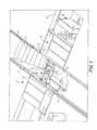
- FIG. 1is a perspective view of a lifting apparatus installed at a site according to the present invention
- FIG. 2is a perspective view of aspects of the lifting apparatus of FIG. 1 shown in a raised position.
- FIG. 3is a perspective view of the aspects of the lifting apparatus of FIGS. 1 and 2 shown in a lowered position.
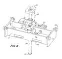
- FIG. 4is a perspective view of a support mechanism as shown in FIG. 1 .
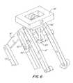
- FIG. 5is a perspective view of a support mechanism which may fit between the tracks of the lifting apparatus shown in FIG. 1 .
- FIG. 6is a detail perspective view of the support mechanism of FIG. 5 shown in an upper position.
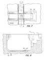
- FIG. 7is a partial top view of the lifting apparatus of FIG. 1
- FIG. 8is a section view along section line 8 - 8 as shown in FIG. 7 .
- FIG. 9is a side view of the lifting apparatus of FIG. 1 .
- FIG. 1a lifting apparatus 2 is shown installed in a pit 3 .
- the lifting apparatusincludes a platform 6 located between rails 4 / 4 ′ of the lifting apparatus.
- a motor support mechanism 8which may be referred to as a traction motor dolly rests between the rails 4 / 4 ′.
- a rail carcan be rolled onto the lifting apparatus such that a wheel assembly of the rail car can be removed.
- one or more jacksare used to support the rail car body in the area adjacent to the wheel assembly to be removed. Not shown in FIG.
- One exemplary removal processincludes positioning the rail car on the rails 4 / 4 ′ and releasing the appropriate wheel assembly from the rail car.
- the rail caris supported by jacks or other supporting mechanisms that contact the rail car body or another location on the rail car.
- the rails 4 / 4 ′are lowered and the base 28 is moved along the floor tracks 80 to align with the secondary rails.
- the rails 4 / 4 ′are lifted and the wheel assembly is moved off the secondary rails in one direction.
- the secondary railscan also include an access passage similar to access passage 5 .
- the motor support mechanism 8includes a block 18 / 18 ′ that displaces vertically to support part of the wheel assembly. In order to remove wheel assemblies from rail cars, it is often required that the weight of a motor is supported so that bolts and fasteners can be removed.
- the pit 3is designed to include an access passage 5 that may include stairs to allow a worker to access the platform 6 in order to release the wheel assembly from the rail car.
- the access passage 5may be positioned between rails 7 / 7 ′.
- the lifting apparatus twoincludes lifting mechanisms positioned below platforms 42 / 42 ′.
- the lifting mechanismmay include links 30 / 32 which are connected at a medial pivot. As shown, one link is connected to a fixed rotation connection 34 and the other link is on a sliding connection 20 / 22 that allows the support 20 to move relative to the rotating pivot 34 .
- the sliding connectionmay be a linear bearing.
- On the opposite end of the linksthere is a rotating pivot 34 ′ and a sliding connection 20 ′/ 22 ′.
- each linkas a rotating pivot on one end and a sliding connection on the other end such that relative movement of the sliding connections causes vertical displacement of the associated platform 42 / 42 ′.
- the movement of the lifting mechanismsis caused by a motor 24 , screw 40 and screw block 41 combination along with a secondary linkage.
- the secondary linkage 70(See FIG. 9 for a side view) includes two arms 36 / 38 that are joined to one of the links 30 / 32 at a medial pivot 78 / 76 such that a hinge 80 can be moved with respect to pivot 31 ′ such that the links rotate with respect to each other as the distance between pivot 31 ′ and hinge 80 changes, thereby causing vertical displacement of the rails 4 / 4 ′ and the platform 42 / 42 ′.
- the base 28 of the lifting apparatusincludes wheels 26 that roll on a track that is located on the floor 82 which may be located in the pit 3 .
- the apparatusis shown at maximum height and in FIG. 3 , the apparatus is shown at minimum height. The difference in the maximum and minimum heights is the travel of the apparatus.
- the lifting mechanismscollapse upon themselves to allow for the minimum height to be relatively small compared to prior art drop tables.
- the motor, links, and armsall are designed to fit under the platform in the void defined between the base cavity 28 ′ and the platform 42 . Since the minimum height is relatively small, the pit depth can likewise be less than traditional drop tables.
- the minimum rail heightis less than 50% of the depth.
- One preferable range of minimum rail height to depthis 50%-10%.
- the total travelis greater than 62.5% of the depth. One preferable range of travel is 62.5%-90% of depth.
- FIG. 4one motor support mechanism 8 is shown with a traveling screw.
- Column 56moves through gearbox 53 which is driven by motor 52 to cause vertical displacement 48 of the column and thus the block 46 .
- the column 56may include a linear gear on one side and the gear box may have a round gear therein where the teeth of the linear gear and the round gear interlock such that rotation of the round gear causes vertical displacement of the column 56 . It is also understood that threads may be used to cause vertical displacement of the column 56 as would be apparent to one of skill in the art.
- the bottom end of the column 57is approximately level with the bottom of the support 49 . When the platforms 40 / 42 are lowered, the column is placed in the upper position 50 to avoid interference with the lower end 57 and the platform 6 .
- the minimum height of the lifting apparatusto remain relatively small and thus allow for a relatively shallow pit depth.
- the lower end 57hangs below the bottom of the support 49 at a distance such that it does not interfere with the platform 6 when the lifting apparatus is at the minimum height. Interference could cause wheels 54 to come out of contact with the platform 42 / 42 ′.
- FIGS. 5 and 6show an alternate embodiment of the motor support mechanism 8 ′.
- screw 56 ′has two threaded blocks 57 ′/ 58 ′ threaded therearound such that rotation of the screw 56 ′ causes the distance between the threaded blocks 57 ′/ 58 ′ to change. This change in distance in turn causes vertical displacement of block 18 ′.
- the screwmay be rotated by motor 52 ′ and chain 59 ′.
- the threaded blocks 57 ′/ 58 ′are connected to support links 10712 ′ and the support links 10712 ′ are connected to each other at connection 11 ′.
- Links 14 ′ and 16 ′are connected to ends of links 10 ′ and 12 ′ respectively.
- Links 60 ′ and 62 ′are connected to each other on one end and respectively to links 14 ′ and 16 ′ on their respective other ends.
- Sliding joint 64 ′ and column 66 ′resist rotation of block 18 ′ if a load is off center on the block 18 ′.
- the column 66 ′slides within sliding joint 64 ′ as the block 18 ′ moves up and down.
- the support mechanismmay include two support links 10712 ′ that are connected to threaded blocks Often upon removal a jack stand is placed under the rail car.
- the support mechanismhangs on the platforms 40 / 42 with wheels 54 so that the support mechanism may be positioned under the wheel assembly at the appropriate location for removal of the wheel assembly.
- the floor tracks 80are shown in additional detail.
- the floor tracksmay be built into an embedment 86 which is sunk into the foundation. Part of the wheels 26 may extend below the floor 82 into gap 84 .
- additional pit depthis saved as prior art designs would usually require mounts positioned on the floor and a track located on top of the mounts. Thus the floor in prior art designs would typically be located below the top of the tracks.
- a pit depth of six (6) feet or lessmay be used where pit depth may be measured between the top of the rails 7 / 7 ′ and the floor 82 .
- the travel of the drop table as measured between minimum rail height (height of rail 4 as shown in FIG. 3 ) and maximum rail height (height of rail 4 as shown in FIG. 2 )may be in the range of 40-60 inches.
- a travel::depth ratiomay be defined as (travel/pit depth). In some cases travel::depth may be greater than 50%, greater than 55%, and/or in the range of 50%-85%.
- a minimum height::depth ratiomay be defined as (minimum height/pit depth). In the example shown in FIG. 3 , the minimum rail height may be two (2) feet.
- a minimum height::depth ratiomay be less than 50%, less than 40%, less than 33%. In one embodiment the minimum height::depth ratio is in the range of 50%-10%.
- a clearancecan be measured between the minimum rail height and the platform. The clearance will typically be equal or greater than the distance which the bottom of the motor support mechanism 8 / 8 ′ hangs below the rails 4 / 4 ′.
- the bottommay be measured at bottom surface 49 when column 56 is in an upwards position.
- the bottommay be measured as the bottom surface of the bottom of the column 57 .
- the columnis movable to minimize the overhang and thus fit within the clearance.
- Motor support mechanism 8 ′is designed so that the bottom hangs below the rails less than or equal to the clearance to enable the lifting mechanism to reach a minimum position while the motor support mechanism 8 remains in contact with the platform.
Landscapes
- Engineering & Computer Science (AREA)
- Mechanical Engineering (AREA)
- Life Sciences & Earth Sciences (AREA)
- Geology (AREA)
- Structural Engineering (AREA)
- Conveying And Assembling Of Building Elements In Situ (AREA)
- Machines For Laying And Maintaining Railways (AREA)
Abstract
Description
- The present invention relates to lifting and positioning machinery, more particularly, the present invention relates to low profile railway drop tables.
- Drop tables are generally known in the art, but suffer from a number of disadvantages. Examples of known drop tables are shown and described in U.S. Pat. No. 2,718,851 to Holdeman and U.S. Pat. No. 2,652,784 to Holmes.
- Holdeman discloses an apparatus for removing and replacing the wheels of a passenger car that operates in a pit intersecting a service track over which vehicles may run. As disclosed, for convenience and safety of the workmen, the table is closed between the rails by a floor plate. Holdeman further discloses an air based lifting mechanism
- Holmes discloses another drop table where rails are positioned at a fixed distance above a working platform where the working platform and rails move up and down allowing for removal of trucks, axle assemblies and the like. Holmes further discloses a vertical screw based lifting mechanism.
- CN202989714, relates to a railway maintenance vehicle having a scissor type mechanism for moving a working
platform 22 up and down. - Due to the configuration of these lifting devices, pits must often be larger than about 6 feet deep. Typically, the deeper the pit, the more dangerous the pit is considered. In many cases, government regulating bodies such as OSHA (Occupational Saftey and Health Administration) regulate pits in factories and repair shops based on depth. For example, additional fall prevention safeguards may be required for pits larger than six feet in depth. In addition, some rail yards may be located in areas where soil moisture content progressively increases as the pit depth increases. At increasing depths, there may be too much water content or even ground water present which inhibits proper installation of a machinery pit.
- Further, many drop tables may be positioned in a pit with multiple parallel track sections passing through the pit. Therefore, the machinery may need a traversing function that allows it to move between the different track sections for installation and/or removal of various parts such as axles. The use of rails in the bottom of the pit further increases requirements for pit depth as the height of the rails must be added to the clearance requirements for the machinery so that the machinery can drop far enough down into the pit for appropriate repair and replacement operations to be completed.
- It is therefore an object of the invention to provide a lifting apparatus that utilizes a relatively shallow pit depth for easier installation, a more compact footprint and lower danger relative to older designs.
- It is yet another object of the invention to provide a lifting apparatus that has a thinner profile in comparison to older designs.
- It is still another object of the invention to provide a lifting apparatus that allows for easier installation.
- It is yet a further object of the invention to provide a lifting apparatus that can be installed at sites where prior art lifting apparatuses could not be installed due to soil, ground water and/or water table constraints.
- These and other objects are achieved by providing a lifting apparatus including two rails spaced apart at a distance and two lifting mechanisms, each lifting mechanism supporting one of the two rails. A platform is disposed between the two rails such that movement of at least one of the lifting mechanisms causes at least one of the rails to displace relative to the platform. The apparatus may further include a base, the two lifting mechanisms connected to the base, and the platform connected to the base. The base is adapted to move horizontally along a floor.
- In one aspect the two rails each define a top surface and the apparatus may further include two lower surfaces located below and between the top surfaces and a support extending between said two lower surfaces. A support mechanism may be connected to the support on one end, the support mechanism moving between extended and retracted positions to cause vertical displacement of another end of the support mechanism in relation to the support.
- In other aspects the support mechanism includes a column and a gearbox rotatable by a drive wherein rotation of the gearbox causes vertical displacement of the column. A first distance is measured vertically between a top surface of at least one the two rails and the platform when the lifting mechanism is in a lowered position. The column may be dimensioned such when the column is in a first position a lower end of the column extends below the two rails at a second distance less than the first distance.
- In other aspects the support mechanism includes a threaded member rotatable by a drive, the threaded member having two threaded blocks threaded therearound such that rotation of the threaded member causes a distance between the two threaded blocks to change. Two support links may be rotatable about one of the two threaded blocks. The support links may be connected to each other at a medial portion of the support links such that displacement of the threaded blocks causes the support links to rotate in opposing directions. A block mechanism may be connected to a block at one end and connected to the support links such that rotation of the support links causes vertical displacement of the block. The block mechanism may further include third and fourth support links connected to the block at the one end of the block mechanism and each connected to one end of one of the two support links. The block mechanism may further include fifth and sixth support links respectively connected to the third and fourth support links and rotatable with respect to each other at a rotation connection. A column may extend from the block to a sliding joint, the sliding joint coupled to the rotation connection such that vertical displacement of the block causes said column to slide within the sliding joint.
- In other aspects, the lifting apparatus includes a track positioned below the base such that the base moves along the track and the floor is positioned in a pit. The track may be recessed into the floor such that wheels associated with the base extend at least partially below the floor.
- In other aspects a minimum rail is height measured as the distance between the floor and a top of at least one of the two rails when the two rails are at a bottom position. A depth is measured from the floor to a top of a fixed rail wherein the fixed rail is located above the floor. A maximum rail height is measured as the distance between the floor and a top of at least one of the two rails when the two rails are at a top position. A travel is defined as the difference between the maximum and minimum rail heights. In some aspects the minimum rail height is less than 50% of the depth. In some aspects the travel is greater than 62.5% of the depth.
- Other objects are achieved by providing a lifting apparatus having two rails spaced apart at a distance and two lifting mechanisms, each lifting mechanism supporting one of the two rails. A platform may be disposed between the two rails such that movement of at least one of the lifting mechanisms causes at least one of the rails to displace relative to the platform. The two lifting mechanisms may each include: two links joined to each other in a medial section by a pivot; and a rotating pivot located at one end of each of said two links, another end of each of the two links having a sliding connection such that rotation of the two links about their respective rotating pivots causes the sliding connections to move relative to the rotating pivots to cause vertical displacement of the pivot.
- In some aspects the lifting apparatus includes a secondary linkage having two arms joined at a first hinge on one end and connected to one of the two links at their respective other ends, wherein connection of the two arms at their respective other ends connects to the respective one of the two links between the one end of the two links and the pivot. A linear displacement device may be connected to the pivot and the first hinge such that displacement of the linear displacement device causes a distance measured between the first hinge and the pivot to change.
- In other aspects, the two rails each define a top surface. Two lower surfaces may be located below and between the top surfaces. A support may extend the two lower surfaces. A support mechanism may be connected to the support on one end, the support mechanism moving between extended and retracted positions to cause vertical displacement of another end of the support mechanism in relation to the support.
- In other aspects the support mechanism includes a column and a gearbox rotatable by a drive wherein rotation of the gearbox causes vertical displacement of the column. A first distance may be measured vertically between a top surface of at least one the two rails and said platform when the lifting mechanism is in a lowered position. The column may be dimensioned such when the column is in a first position a lower end of the column extends below the two rails at a second distance less than the first distance.
- In other aspects, the support mechanism includes a threaded member rotatable by a drive, the threaded member having two threaded blocks threaded therearound such that rotation of the threaded member causes a distance between the two threaded blocks to change. Two support links may each be rotatable about one of the two threaded blocks. The support links may be connected to each other at a medial portion such that displacement of the threaded blocks causes the support links to rotate in opposing directions. A block mechanism may be connected to a block at one end and connected to the support links such that rotation of the support links causes vertical displacement of the block.
- In other aspects a track may be positioned below the base such that the base moves along the track and the floor is positioned in a pit. The track may be recessed into the floor such that wheels associated with the base extend at least partially below the floor.
- The block mechanism may further include third and fourth support links connected to the block at the one end said block mechanism and each connected to one end of one of the two support links. Fifth and sixth support links may be respectively connected to the third and fourth support links and rotatable with respect to each other at a rotation connection. A column may extend from the block to a sliding joint, the sliding joint coupled to the rotation connection such that vertical displacement of the block causes the column to slide within the sliding joint.
- Other objects are achieved by providing a lifting apparatus including two rails spaced apart at a distance and two lifting mechanisms, each lifting mechanism supporting one of the two rails. A platform may be disposed between the two rails such that movement of at least one of the lifting mechanisms causes at least one of the rails to displace relative to the platform. A base may have the two lifting mechanisms connected thereto, where the platform may be connected to the base. The base may be adapted to move horizontally along a floor. The two lifting mechanisms may each include: two links joined to each other in a medial section by a pivot; and a rotating pivot located at one end of each of the two links, another end of each of the two links having a sliding connection such that rotation of the two links about their respective rotating pivots causes the sliding connections to move relative to the rotating pivots to cause vertical displacement of the pivot.
- In some aspects the two lifting mechanisms further comprise: a secondary linkage having two arms joined at a first hinge on one end and connected to one of the two links at their respective other ends, wherein connection of the two arms at their respective other ends connects to the respective one of the two links between the one end of the two links and the pivot; and a linear displacement device connected to the pivot and the first hinge such that displacement of the linear displacement device causes a distance measured between the first hinge and the pivot to change.
- In some aspects the two rails each define a top surface two lower surfaces may be located below and between the top surfaces. A support may extend between the two lower surfaces. A support mechanism may be connected to the support on one end, the support mechanism moving between extended and retracted positions to cause vertical displacement of another end of the support mechanism in relation to the support.
- In some aspects, the support mechanism includes one or more of: a column; a gearbox rotatable by a drive wherein rotation of the gearbox causes vertical displacement of the column; a first distance measured vertically between a top surface of at least one said two rails and said platform when said lifting mechanism is in a lowered position; the column dimensioned such when the column is in a first position a lower end of said column extends below the two rails at a second distance less than the first distance.
- In other aspects, the support mechanism may include a threaded member rotatable by a drive, the threaded member having two threaded blocks threaded therearound such that rotation of the threaded member causes a distance between the two threaded blocks to change. Two support links may be each rotatable about one of the two threaded blocks. The support links may be connected to each other at a medial portion such that displacement of the threaded blocks causes the support links to rotate in opposing directions. A block mechanism may be connected to a block at one end and connected to the support links such that rotation of the support links causes vertical displacement of the block.
- In other aspects the block mechanism includes third and fourth support links connected to the block at the one end said block mechanism and each connected to one end of one of the two support links. Fifth and sixth support links may be respectively connected to the third and fourth support links and rotatable with respect to each other at a rotation connection. A column may extend from the block to a sliding joint, the sliding joint coupled to the rotation connection such that vertical displacement of the block causes the column to slide within the sliding joint.
- In other aspects the lifting apparatus includes a track positioned below the base such that the base moves along the track and the floor is positioned in a pit. The track may be recessed into the floor such that wheels associated with the base extend at least partially below the floor.
- In other aspects a minimum rail is height measured as the distance between the floor and a top of at least one of the two rails when the two rails are at a bottom position. A depth is measured from the floor to a top of a fixed rail wherein the fixed rail is located above the floor. A maximum rail height is measured as the distance between the floor and a top of at least one of the two rails when the two rails are at a top position. A travel is defined as the difference between the maximum and minimum rail heights. In some aspects the minimum rail height is less than 50% of the depth. In some aspects the travel is greater than 62.5% of the depth.
- Other objects of the invention and its particular features and advantages will become more apparent from consideration of the following drawings, claims and accompanying detailed description. It is still further contemplated that it may be advantageous, depending upon the application, to utilize all or any portion of the functions or combinations of functions described herein.
FIG. 1 is a perspective view of a lifting apparatus installed at a site according to the present inventionFIG. 2 is a perspective view of aspects of the lifting apparatus ofFIG. 1 shown in a raised position.FIG. 3 is a perspective view of the aspects of the lifting apparatus ofFIGS. 1 and 2 shown in a lowered position.FIG. 4 is a perspective view of a support mechanism as shown inFIG. 1 .FIG. 5 is a perspective view of a support mechanism which may fit between the tracks of the lifting apparatus shown inFIG. 1 .FIG. 6 is a detail perspective view of the support mechanism ofFIG. 5 shown in an upper position.FIG. 7 is a partial top view of the lifting apparatus ofFIG. 1 FIG. 8 is a section view along section line8-8 as shown inFIG. 7 .FIG. 9 is a side view of the lifting apparatus ofFIG. 1 .- Referring now to the drawings, wherein like reference numerals designate corresponding structure throughout the views. In
FIG. 1 , alifting apparatus 2 is shown installed in a pit3. The lifting apparatus includes aplatform 6 located betweenrails 4/4′ of the lifting apparatus. Amotor support mechanism 8, which may be referred to as a traction motor dolly rests between therails 4/4′. When therails 4/4′ are aligned withrails 7/7′ a rail car can be rolled onto the lifting apparatus such that a wheel assembly of the rail car can be removed. In order to facilitate removal, one or more jacks are used to support the rail car body in the area adjacent to the wheel assembly to be removed. Not shown inFIG. 1 is a secondary set of rails that are optionally parallel torails 7/7′ such that thelifting apparatus 2 can move along the floor tracks80 to align with the secondary set of rails. One exemplary removal process includes positioning the rail car on therails 4/4′ and releasing the appropriate wheel assembly from the rail car. The rail car is supported by jacks or other supporting mechanisms that contact the rail car body or another location on the rail car. Therails 4/4′ are lowered and thebase 28 is moved along the floor tracks80 to align with the secondary rails. Therails 4/4′ are lifted and the wheel assembly is moved off the secondary rails in one direction. Along the other direction of the secondary rails, a new or repaired wheel assembly is moved over therails 4/4′ which are then lowered and moved into alignment under the rail car. Then the new or repaired wheel assembly is lifted into position and attached to the rail car. The secondary rails can also include an access passage similar to accesspassage 5. - The
motor support mechanism 8 includes ablock 18/18′ that displaces vertically to support part of the wheel assembly. In order to remove wheel assemblies from rail cars, it is often required that the weight of a motor is supported so that bolts and fasteners can be removed. The pit3 is designed to include anaccess passage 5 that may include stairs to allow a worker to access theplatform 6 in order to release the wheel assembly from the rail car. Theaccess passage 5 may be positioned betweenrails 7/7′. - The lifting apparatus two (2) includes lifting mechanisms positioned below
platforms 42/42′. The lifting mechanism may includelinks 30/32 which are connected at a medial pivot. As shown, one link is connected to afixed rotation connection 34 and the other link is on a slidingconnection 20/22 that allows thesupport 20 to move relative to therotating pivot 34. The sliding connection may be a linear bearing. On the opposite end of the links, there is arotating pivot 34′ and a slidingconnection 20′/22′. Thus, each link as a rotating pivot on one end and a sliding connection on the other end such that relative movement of the sliding connections causes vertical displacement of the associatedplatform 42/42′. The movement of the lifting mechanisms is caused by amotor 24,screw 40 andscrew block 41 combination along with a secondary linkage. - The secondary linkage70 (See
FIG. 9 for a side view) includes twoarms 36/38 that are joined to one of thelinks 30/32 at amedial pivot 78/76 such that ahinge 80 can be moved with respect to pivot31′ such that the links rotate with respect to each other as the distance betweenpivot 31′ and hinge80 changes, thereby causing vertical displacement of therails 4/4′ and theplatform 42/42′. - The
base 28 of the lifting apparatus includeswheels 26 that roll on a track that is located on thefloor 82 which may be located in the pit3. InFIG. 2 , the apparatus is shown at maximum height and inFIG. 3 , the apparatus is shown at minimum height. The difference in the maximum and minimum heights is the travel of the apparatus. - As can be seen in
FIG. 3 , the lifting mechanisms collapse upon themselves to allow for the minimum height to be relatively small compared to prior art drop tables. The motor, links, and arms all are designed to fit under the platform in the void defined between thebase cavity 28′ and theplatform 42. Since the minimum height is relatively small, the pit depth can likewise be less than traditional drop tables. In some examples the minimum rail height is less than 50% of the depth. One preferable range of minimum rail height to depth is 50%-10%. Also, in some examples the total travel is greater than 62.5% of the depth. One preferable range of travel is 62.5%-90% of depth. - In
FIG. 4 onemotor support mechanism 8 is shown with a traveling screw.Column 56 moves through gearbox53 which is driven bymotor 52 to cause vertical displacement48 of the column and thus theblock 46. Thecolumn 56 may include a linear gear on one side and the gear box may have a round gear therein where the teeth of the linear gear and the round gear interlock such that rotation of the round gear causes vertical displacement of thecolumn 56. It is also understood that threads may be used to cause vertical displacement of thecolumn 56 as would be apparent to one of skill in the art. In the upper position50, the bottom end of thecolumn 57 is approximately level with the bottom of thesupport 49. When theplatforms 40/42 are lowered, the column is placed in the upper position50 to avoid interference with thelower end 57 and theplatform 6. This further allows the minimum height of the lifting apparatus to remain relatively small and thus allow for a relatively shallow pit depth. In some cases, thelower end 57 hangs below the bottom of thesupport 49 at a distance such that it does not interfere with theplatform 6 when the lifting apparatus is at the minimum height. Interference could causewheels 54 to come out of contact with theplatform 42/42′. FIGS. 5 and 6 show an alternate embodiment of themotor support mechanism 8′. In this embodiment, screw56′ has two threadedblocks 57′/58′ threaded therearound such that rotation of thescrew 56′ causes the distance between the threadedblocks 57′/58′ to change. This change in distance in turn causes vertical displacement ofblock 18′. The screw may be rotated bymotor 52′ and chain59′. The threaded blocks57′/58′ are connected to support links10712′ and the support links10712′ are connected to each other at connection11′.Links 14′ and16′ are connected to ends of links10′ and12′ respectively. Links60′ and62′ are connected to each other on one end and respectively tolinks 14′ and16′ on their respective other ends. Sliding joint64′ and column66′ resist rotation ofblock 18′ if a load is off center on theblock 18′. The column66′ slides within sliding joint64′ as theblock 18′ moves up and down.- The support mechanism may include two support links10712′ that are connected to threaded blocks Often upon removal a jack stand is placed under the rail car. The support mechanism hangs on the
platforms 40/42 withwheels 54 so that the support mechanism may be positioned under the wheel assembly at the appropriate location for removal of the wheel assembly. - In
FIGS. 7 and 8 , the floor tracks80 are shown in additional detail. Thefloor 82 of the pit or foundation. As shown, the floor tracks80 are approximately level with thefloor 82. The floor tracks may be built into anembedment 86 which is sunk into the foundation. Part of thewheels 26 may extend below thefloor 82 intogap 84. By recessing the floor tracks80 in thefloor 82, additional pit depth is saved as prior art designs would usually require mounts positioned on the floor and a track located on top of the mounts. Thus the floor in prior art designs would typically be located below the top of the tracks. - In one embodiment a pit depth of six (6) feet or less may be used where pit depth may be measured between the top of the
rails 7/7′ and thefloor 82. The travel of the drop table as measured between minimum rail height (height ofrail 4 as shown inFIG. 3 ) and maximum rail height (height ofrail 4 as shown inFIG. 2 ) may be in the range of 40-60 inches. A travel::depth ratio may be defined as (travel/pit depth). In some cases travel::depth may be greater than 50%, greater than 55%, and/or in the range of 50%-85%. A minimum height::depth ratio may be defined as (minimum height/pit depth). In the example shown inFIG. 3 , the minimum rail height may be two (2) feet. In some cases, a minimum height::depth ratio may be less than 50%, less than 40%, less than 33%. In one embodiment the minimum height::depth ratio is in the range of 50%-10%. In the example ofFIG. 3 , a clearance can be measured between the minimum rail height and the platform. The clearance will typically be equal or greater than the distance which the bottom of themotor support mechanism 8/8′ hangs below therails 4/4′. For example, the bottom may be measured atbottom surface 49 whencolumn 56 is in an upwards position. In some cases, the bottom may be measured as the bottom surface of the bottom of thecolumn 57. As can be seen in themotor support mechanism 8, the column is movable to minimize the overhang and thus fit within the clearance.Motor support mechanism 8′ is designed so that the bottom hangs below the rails less than or equal to the clearance to enable the lifting mechanism to reach a minimum position while themotor support mechanism 8 remains in contact with the platform. - Although the invention has been described with reference to a particular arrangement of parts, features and the like, these are not intended to exhaust all possible arrangements or features, and indeed many other modifications and variations will be ascertainable to those of skill in the art.
Claims (26)
Priority Applications (2)
| Application Number | Priority Date | Filing Date | Title |
|---|---|---|---|
| US14/454,318US10730727B2 (en) | 2014-08-07 | 2014-08-07 | Low profile drop table |
| CA2897863ACA2897863C (en) | 2014-08-07 | 2015-07-15 | Low profile drop table |
Applications Claiming Priority (1)
| Application Number | Priority Date | Filing Date | Title |
|---|---|---|---|
| US14/454,318US10730727B2 (en) | 2014-08-07 | 2014-08-07 | Low profile drop table |
Publications (2)
| Publication Number | Publication Date |
|---|---|
| US20160039646A1true US20160039646A1 (en) | 2016-02-11 |
| US10730727B2 US10730727B2 (en) | 2020-08-04 |
Family
ID=55266887
Family Applications (1)
| Application Number | Title | Priority Date | Filing Date |
|---|---|---|---|
| US14/454,318Active2036-02-08US10730727B2 (en) | 2014-08-07 | 2014-08-07 | Low profile drop table |
Country Status (2)
| Country | Link |
|---|---|
| US (1) | US10730727B2 (en) |
| CA (1) | CA2897863C (en) |
Cited By (12)
| Publication number | Priority date | Publication date | Assignee | Title |
|---|---|---|---|---|
| US20140263932A1 (en)* | 2013-03-15 | 2014-09-18 | Thomas C. Schroeder | Rotary Actuator Driven Vibration Isolation |
| CN107235444A (en)* | 2017-06-05 | 2017-10-10 | 邯钢集团邯宝钢铁有限公司 | A kind of cold rolling mill hydraulic cylinder changing device |
| US10046956B2 (en)* | 2013-02-26 | 2018-08-14 | Stertil B.V. | Lifting column, lifting system and method for lifting a vehicle such as a rail-car |
| CN111410151A (en)* | 2020-05-13 | 2020-07-14 | 晋江市创科科技有限公司 | Special carrying device for large vehicle maintenance trench and use method thereof |
| US20210053807A1 (en)* | 2019-08-22 | 2021-02-25 | Stertil B.V. | Flexible In-Ground Lifting System for Lifting a Vehicle and Method Therefor |
| GB2594080A (en)* | 2020-04-16 | 2021-10-20 | Toumazis Antonios | Scissor mechanism |
| US11198599B2 (en)* | 2019-04-25 | 2021-12-14 | Yasui Corporation | Vehicle lift device |
| CN113955669A (en)* | 2021-09-26 | 2022-01-21 | 四川职业技术学院 | Landing gear for automobile maintenance |
| US11383960B2 (en)* | 2019-07-02 | 2022-07-12 | Nabholz Construction Corporation | Drop table with motor feedback |
| US11390503B2 (en) | 2019-07-02 | 2022-07-19 | Nabholz Construction Corporation | Drop table with shearing drive coupling |
| US11498817B2 (en) | 2019-07-02 | 2022-11-15 | Nabholz Construction Corporation | Nut gap monitoring system |
| US11731866B2 (en) | 2019-08-22 | 2023-08-22 | Stertil B.V. | In-ground lifting system for lifting a vehicle comprising a cover, and method for lifting a vehicle |
Families Citing this family (1)
| Publication number | Priority date | Publication date | Assignee | Title |
|---|---|---|---|---|
| US12392607B2 (en)* | 2020-06-25 | 2025-08-19 | Nabholz Construction Corporation | Intelligent drop table |
Citations (44)
| Publication number | Priority date | Publication date | Assignee | Title |
|---|---|---|---|---|
| US819592A (en)* | 1905-10-04 | 1906-05-01 | Longan C Phillips | Lifting mechanism. |
| US1706211A (en)* | 1929-03-19 | Mechanism | ||
| US1748696A (en)* | 1925-01-16 | 1930-02-25 | Ohio Brass Co | Cable-terminal housing |
| US1772848A (en)* | 1928-02-29 | 1930-08-12 | Whiting Corp | Drop pit |
| US1802592A (en)* | 1930-02-17 | 1931-04-28 | Whiting Corp | Drop pit |
| US1847719A (en)* | 1931-10-12 | 1932-03-01 | George H Hirschel | Rack device |
| US1859830A (en)* | 1928-12-24 | 1932-05-24 | Eugen Rahm | Hydraulic lifting jack |
| US2111917A (en)* | 1937-06-26 | 1938-03-22 | Manning Maxwell & Moore Inc | Drop pit apparatus |
| US2178632A (en)* | 1936-05-01 | 1939-11-07 | Whiting Corp | Drop pit apparatus |
| US2178851A (en)* | 1936-09-19 | 1939-11-07 | Lubrication Corp | Lubricating device |
| US2191710A (en)* | 1938-12-08 | 1940-02-27 | Whiting Corp | Drop pit apparatus |
| US2196468A (en)* | 1935-11-07 | 1940-04-09 | Manning Maxwell & Moore Inc | Drop pit apparatus |
| US2454225A (en)* | 1947-07-31 | 1948-11-16 | Whiting Corp | Apparatus for supporting bodies of railway vehicles in connection with removal and replacement of the trucks thereof |
| US2655115A (en)* | 1950-08-24 | 1953-10-13 | Manning Maxwell & Moore Inc | Drop pit apparatus |
| US3367449A (en)* | 1967-06-08 | 1968-02-06 | James J. Pelouch | Vehicle lift |
| US3393772A (en)* | 1967-06-14 | 1968-07-23 | James J. Pelouch | Vehicle lift |
| US3558103A (en)* | 1966-09-26 | 1971-01-26 | Alois Lodige | Scissor action hoist with components shaped so as to nest within one another |
| US3563345A (en)* | 1968-11-12 | 1971-02-16 | Applied Power Ind Inc | Lifting device |
| US3931895A (en)* | 1974-11-01 | 1976-01-13 | Samuel Grimaldo | Collapsible trailer hoist |
| US4447042A (en)* | 1981-04-06 | 1984-05-08 | Yasui Sangyo Co., Ltd. | Vehicle lift |
| US4491194A (en)* | 1982-11-22 | 1985-01-01 | Ammco Tools, Inc. | Vehicle lift rack and jack assembly |
| US4624448A (en)* | 1985-05-28 | 1986-11-25 | Lawman Dennis J | Low profile, high rising lifting mechanism |
| DE9108825U1 (en)* | 1991-02-28 | 1991-11-14 | Langewellpott, Ernst, 4992 Espelkamp | Scissor lift table |
| US5215287A (en)* | 1990-07-30 | 1993-06-01 | Lenet Leski | Vehicle lifter |
| US5285992A (en)* | 1992-07-14 | 1994-02-15 | Brown Ronald G | Adjustable step stool |
| US5370058A (en)* | 1993-11-15 | 1994-12-06 | Whiting Equipment Canada Inc. | Low rise drop yoke system |
| US5404968A (en)* | 1994-02-09 | 1995-04-11 | Advantage Lift Systems, Inc. | Automotive screw lift system with interchangeable components |
| US5694864A (en)* | 1993-10-27 | 1997-12-09 | Johann Stamm | Scissor lift table |
| US6186279B1 (en)* | 1999-07-14 | 2001-02-13 | Ron Darrell Blocker | Low-rise vehicle lift for use over a pit |
| US6257371B1 (en)* | 1998-07-13 | 2001-07-10 | Maha Mashinenbau Haldenwang Gmbh & Co. Kg | Lifting platform for double-tracked vehicles |
| DE102004027215A1 (en)* | 2004-06-03 | 2005-12-29 | Flexlift-Hubgeräte GmbH | Lifting platform, with scissors structures, has a drive motor and nut on a rotating spindle linked to a scissors bar connection point and by struts to the scissors bars |
| US20060026762A1 (en)* | 2004-07-28 | 2006-02-09 | Hornbach David M | Hospital bed |
| US20070051932A1 (en)* | 2005-09-08 | 2007-03-08 | Tae-Hong Ha | Cylinder apparatus for hydraulic lift jack with transmission |
| US20080224107A1 (en)* | 2004-05-17 | 2008-09-18 | Polins Kurt E | Device and System For Lifting a Motor Vehicle |
| DE102009025493A1 (en)* | 2009-06-19 | 2011-01-05 | Schwaderlapp Engineering Gmbh | Device for lifting and lowering load bodies, particularly for lifting motor vehicles and hulls, has lifting unit with four support arms in X-shaped arrangement |
| US7900562B2 (en)* | 2007-10-12 | 2011-03-08 | Macton Corporation | Split rail trolley system |
| US20110240409A1 (en)* | 2010-04-02 | 2011-10-06 | Herkules Equipment Corporation | Scissor lift assembly |
| DE202011104094U1 (en)* | 2011-07-15 | 2011-11-14 | Elena Albrecht | Spindelhubtisch |
| US20120048653A1 (en)* | 2009-05-07 | 2012-03-01 | Vehicle Service Group, Llc | Multi-link automotive alignment lift |
| US20120313059A1 (en)* | 2011-06-10 | 2012-12-13 | Stephen Greg Litcher | Laboratory jack |
| US20150166313A1 (en)* | 2013-12-12 | 2015-06-18 | Ryan W. Knapp | Machinery Positioning Apparatus Having Independent Drive Columns |
| US20160052757A1 (en)* | 2014-07-04 | 2016-02-25 | Stertil B.V. | Lifting Device and System with Integrated Drive Unit for Lifting a Vehicle, and Method There For |
| US20170030092A1 (en)* | 2015-07-27 | 2017-02-02 | Ronald Young | Kitchen cabinet installation device |
| US9764934B2 (en)* | 2013-12-12 | 2017-09-19 | Macton Corporation | Independent drive motors for machinery positioning apparatus having independent lifting motors |
Family Cites Families (10)
| Publication number | Priority date | Publication date | Assignee | Title |
|---|---|---|---|---|
| USRE16989E (en) | 1928-06-05 | Hydraulic jack | ||
| US2454226A (en)* | 1947-10-31 | 1948-11-16 | Whiting Corp | Drop table apparatus for use in servicing trucks and wheels of railway vehicles |
| US2652784A (en) | 1950-01-14 | 1953-09-22 | Whiting Corp | Drop pit apparatus |
| US2718851A (en) | 1950-02-28 | 1955-09-27 | Manning Maxwell & Moore Inc | Drop pit apparatus |
| US2640435A (en) | 1950-04-13 | 1953-06-02 | Whiting Corp | Side release table for servicing railroad vehicles and the like |
| JPH07157292A (en) | 1993-12-08 | 1995-06-20 | Nippon Steel Corp | Pallet conveyer |
| JP2004268837A (en) | 2003-03-11 | 2004-09-30 | Universal Kiki Kk | Traverser for vehicle |
| CN202989714U (en) | 2012-12-06 | 2013-06-12 | 中铁第四勘察设计院集团有限公司 | Trench repairing vehicle of railway large road maintenance mechanical equipment |
| US9045149B2 (en)* | 2013-03-14 | 2015-06-02 | The Macton Corporation | Machinery foundation module |
| US10000221B2 (en)* | 2014-07-14 | 2018-06-19 | Macton Corporation | Pit cover |
- 2014
- 2014-08-07USUS14/454,318patent/US10730727B2/enactiveActive
- 2015
- 2015-07-15CACA2897863Apatent/CA2897863C/ennot_activeExpired - Fee Related
Patent Citations (47)
| Publication number | Priority date | Publication date | Assignee | Title |
|---|---|---|---|---|
| US1706211A (en)* | 1929-03-19 | Mechanism | ||
| US819592A (en)* | 1905-10-04 | 1906-05-01 | Longan C Phillips | Lifting mechanism. |
| US1748696A (en)* | 1925-01-16 | 1930-02-25 | Ohio Brass Co | Cable-terminal housing |
| US1772848A (en)* | 1928-02-29 | 1930-08-12 | Whiting Corp | Drop pit |
| US1859830A (en)* | 1928-12-24 | 1932-05-24 | Eugen Rahm | Hydraulic lifting jack |
| US1802592A (en)* | 1930-02-17 | 1931-04-28 | Whiting Corp | Drop pit |
| US1847719A (en)* | 1931-10-12 | 1932-03-01 | George H Hirschel | Rack device |
| US2196468A (en)* | 1935-11-07 | 1940-04-09 | Manning Maxwell & Moore Inc | Drop pit apparatus |
| US2178632A (en)* | 1936-05-01 | 1939-11-07 | Whiting Corp | Drop pit apparatus |
| US2178851A (en)* | 1936-09-19 | 1939-11-07 | Lubrication Corp | Lubricating device |
| US2111917A (en)* | 1937-06-26 | 1938-03-22 | Manning Maxwell & Moore Inc | Drop pit apparatus |
| US2191710A (en)* | 1938-12-08 | 1940-02-27 | Whiting Corp | Drop pit apparatus |
| US2454225A (en)* | 1947-07-31 | 1948-11-16 | Whiting Corp | Apparatus for supporting bodies of railway vehicles in connection with removal and replacement of the trucks thereof |
| US2655115A (en)* | 1950-08-24 | 1953-10-13 | Manning Maxwell & Moore Inc | Drop pit apparatus |
| US3558103A (en)* | 1966-09-26 | 1971-01-26 | Alois Lodige | Scissor action hoist with components shaped so as to nest within one another |
| US3367449A (en)* | 1967-06-08 | 1968-02-06 | James J. Pelouch | Vehicle lift |
| US3393772A (en)* | 1967-06-14 | 1968-07-23 | James J. Pelouch | Vehicle lift |
| US3563345A (en)* | 1968-11-12 | 1971-02-16 | Applied Power Ind Inc | Lifting device |
| US3931895A (en)* | 1974-11-01 | 1976-01-13 | Samuel Grimaldo | Collapsible trailer hoist |
| US4447042A (en)* | 1981-04-06 | 1984-05-08 | Yasui Sangyo Co., Ltd. | Vehicle lift |
| US4491194A (en)* | 1982-11-22 | 1985-01-01 | Ammco Tools, Inc. | Vehicle lift rack and jack assembly |
| US4624448A (en)* | 1985-05-28 | 1986-11-25 | Lawman Dennis J | Low profile, high rising lifting mechanism |
| US5215287A (en)* | 1990-07-30 | 1993-06-01 | Lenet Leski | Vehicle lifter |
| DE9108825U1 (en)* | 1991-02-28 | 1991-11-14 | Langewellpott, Ernst, 4992 Espelkamp | Scissor lift table |
| EP0501254A2 (en)* | 1991-02-28 | 1992-09-02 | Stamm, Johann | Scissor type lifting table |
| US5285992A (en)* | 1992-07-14 | 1994-02-15 | Brown Ronald G | Adjustable step stool |
| US5694864A (en)* | 1993-10-27 | 1997-12-09 | Johann Stamm | Scissor lift table |
| US5370058A (en)* | 1993-11-15 | 1994-12-06 | Whiting Equipment Canada Inc. | Low rise drop yoke system |
| US5404968A (en)* | 1994-02-09 | 1995-04-11 | Advantage Lift Systems, Inc. | Automotive screw lift system with interchangeable components |
| US6257371B1 (en)* | 1998-07-13 | 2001-07-10 | Maha Mashinenbau Haldenwang Gmbh & Co. Kg | Lifting platform for double-tracked vehicles |
| US6186279B1 (en)* | 1999-07-14 | 2001-02-13 | Ron Darrell Blocker | Low-rise vehicle lift for use over a pit |
| US20080224107A1 (en)* | 2004-05-17 | 2008-09-18 | Polins Kurt E | Device and System For Lifting a Motor Vehicle |
| DE102004027215A1 (en)* | 2004-06-03 | 2005-12-29 | Flexlift-Hubgeräte GmbH | Lifting platform, with scissors structures, has a drive motor and nut on a rotating spindle linked to a scissors bar connection point and by struts to the scissors bars |
| US7886380B2 (en)* | 2004-07-28 | 2011-02-15 | Hill-Rom Services, Inc. | Hospital bed |
| US20060026762A1 (en)* | 2004-07-28 | 2006-02-09 | Hornbach David M | Hospital bed |
| US20070051932A1 (en)* | 2005-09-08 | 2007-03-08 | Tae-Hong Ha | Cylinder apparatus for hydraulic lift jack with transmission |
| US7900562B2 (en)* | 2007-10-12 | 2011-03-08 | Macton Corporation | Split rail trolley system |
| US20120048653A1 (en)* | 2009-05-07 | 2012-03-01 | Vehicle Service Group, Llc | Multi-link automotive alignment lift |
| DE102009025493A1 (en)* | 2009-06-19 | 2011-01-05 | Schwaderlapp Engineering Gmbh | Device for lifting and lowering load bodies, particularly for lifting motor vehicles and hulls, has lifting unit with four support arms in X-shaped arrangement |
| US20110240409A1 (en)* | 2010-04-02 | 2011-10-06 | Herkules Equipment Corporation | Scissor lift assembly |
| US20120313059A1 (en)* | 2011-06-10 | 2012-12-13 | Stephen Greg Litcher | Laboratory jack |
| DE202011104094U1 (en)* | 2011-07-15 | 2011-11-14 | Elena Albrecht | Spindelhubtisch |
| EP2731901B1 (en)* | 2011-07-15 | 2015-05-06 | Albrecht, Elena | Spindle-operated elevating table |
| US20150166313A1 (en)* | 2013-12-12 | 2015-06-18 | Ryan W. Knapp | Machinery Positioning Apparatus Having Independent Drive Columns |
| US9764934B2 (en)* | 2013-12-12 | 2017-09-19 | Macton Corporation | Independent drive motors for machinery positioning apparatus having independent lifting motors |
| US20160052757A1 (en)* | 2014-07-04 | 2016-02-25 | Stertil B.V. | Lifting Device and System with Integrated Drive Unit for Lifting a Vehicle, and Method There For |
| US20170030092A1 (en)* | 2015-07-27 | 2017-02-02 | Ronald Young | Kitchen cabinet installation device |
Non-Patent Citations (8)
| Title |
|---|
| Hatfield (Moose Jaw Yard Visir: Wheels Drop Table; Published on Jun 25, 2014)* |
| Hunter P441 and P444 Alignment Pit System; Copyright 2015. Hunter Engineering Company* |
| Hunter PF Heavy Duty Alignment Pit System; Copyright 2015. Hunter Engineering Company* |
| Hunter Pit Racks For Heavy-Duty Trucks and Buses; Copyright 2010. Hunter Engineering Company* |
| Hunter Pit Racks For Heavy-Duty Trucks and Buses; Copyright 2017. Hunter Engineering Company* |
| Hunter Pit Racks For passenger cars and light trucks; Copyright 2017. Hunter Engineering Company* |
| Railquip1 (Drop Table Railquip, Published on Nov. 30, 2011)* |
| Railquip2 Truck Drop Table Exchange Systems Railquip; Published on Dec. 2, 2011)* |
Cited By (13)
| Publication number | Priority date | Publication date | Assignee | Title |
|---|---|---|---|---|
| US10046956B2 (en)* | 2013-02-26 | 2018-08-14 | Stertil B.V. | Lifting column, lifting system and method for lifting a vehicle such as a rail-car |
| US20140263932A1 (en)* | 2013-03-15 | 2014-09-18 | Thomas C. Schroeder | Rotary Actuator Driven Vibration Isolation |
| US11353084B2 (en)* | 2013-03-15 | 2022-06-07 | Clearmotion Acquisition I Llc | Rotary actuator driven vibration isolation |
| CN107235444A (en)* | 2017-06-05 | 2017-10-10 | 邯钢集团邯宝钢铁有限公司 | A kind of cold rolling mill hydraulic cylinder changing device |
| US11198599B2 (en)* | 2019-04-25 | 2021-12-14 | Yasui Corporation | Vehicle lift device |
| US11383960B2 (en)* | 2019-07-02 | 2022-07-12 | Nabholz Construction Corporation | Drop table with motor feedback |
| US11390503B2 (en) | 2019-07-02 | 2022-07-19 | Nabholz Construction Corporation | Drop table with shearing drive coupling |
| US11498817B2 (en) | 2019-07-02 | 2022-11-15 | Nabholz Construction Corporation | Nut gap monitoring system |
| US20210053807A1 (en)* | 2019-08-22 | 2021-02-25 | Stertil B.V. | Flexible In-Ground Lifting System for Lifting a Vehicle and Method Therefor |
| US11731866B2 (en) | 2019-08-22 | 2023-08-22 | Stertil B.V. | In-ground lifting system for lifting a vehicle comprising a cover, and method for lifting a vehicle |
| GB2594080A (en)* | 2020-04-16 | 2021-10-20 | Toumazis Antonios | Scissor mechanism |
| CN111410151A (en)* | 2020-05-13 | 2020-07-14 | 晋江市创科科技有限公司 | Special carrying device for large vehicle maintenance trench and use method thereof |
| CN113955669A (en)* | 2021-09-26 | 2022-01-21 | 四川职业技术学院 | Landing gear for automobile maintenance |
Also Published As
| Publication number | Publication date |
|---|---|
| CA2897863C (en) | 2019-09-10 |
| CA2897863A1 (en) | 2016-02-07 |
| US10730727B2 (en) | 2020-08-04 |
Similar Documents
| Publication | Publication Date | Title |
|---|---|---|
| US10730727B2 (en) | Low profile drop table | |
| CN113200308B (en) | Motor train unit lower part dismounting device with lifting function | |
| KR100955531B1 (en) | Frame scaffolding for railway track | |
| CN110655015B (en) | A trackless self-propelled platform vehicle for subway tunnel maintenance | |
| JP7173696B2 (en) | Bogie exchange equipment for railway vehicles | |
| KR102109969B1 (en) | A work bogie for tunnel work | |
| DE202006010225U1 (en) | Low floor components e.g. bogie, changing device for e.g. clock train, has changing mechanism designed as assembly tray attached to sink hole, where tray is connected with track standing at angle to rail sections in lowered condition | |
| RU2351497C1 (en) | Method and device to change wheel pairs by mobile device | |
| US1586783A (en) | Ophthalmic lens | |
| RU2626425C1 (en) | Method for replacing wheel pairs of railway carriage (versions) | |
| CN102774624B (en) | Overhaul and transport vehicle and overhauling and transport method | |
| CN220224787U (en) | Sideslip system for track equipment | |
| US1834900A (en) | Automobile lift | |
| GB2465570A (en) | Vehicle support assembly and lifting device. | |
| US20060086568A1 (en) | Scaffolding structure | |
| WO2023240355A1 (en) | Four post workpiece lift for sportsvehicles and small machines | |
| CN106218666B (en) | Hydraulic pressure re-railing block | |
| CN211142825U (en) | Simple universal beam transporting trolley | |
| CN210480743U (en) | Jacking device for civil engineering | |
| CN110843825B (en) | An axle box rescue vehicle | |
| CN204399199U (en) | A kind of rolling stock wheel shaft reloader | |
| DE2619504A1 (en) | LAYING SYSTEM FOR SLEEPERS, RAILS AND GLEISJOCHE | |
| CN222809137U (en) | Anti-overturning device for traveling mechanism track arrangement | |
| US20070180788A1 (en) | Adjustable floor system for installation inside a repair pit | |
| CN220720736U (en) | Wheel changing device of monorail vehicle |
Legal Events
| Date | Code | Title | Description |
|---|---|---|---|
| AS | Assignment | Owner name:THE MACTON CORPORATION, CONNECTICUT Free format text:ASSIGNMENT OF ASSIGNORS INTEREST;ASSIGNOR:KNAPP, RYAN W.;REEL/FRAME:033544/0151 Effective date:20140804 | |
| AS | Assignment | Owner name:THE MACTON CONSOLIDATION CORPORATION, CONNECTICUT Free format text:MERGER;ASSIGNOR:THE MACTON CORPORATION;REEL/FRAME:039566/0185 Effective date:20141217 Owner name:MACTON CORPORATION, CONNECTICUT Free format text:CHANGE OF NAME;ASSIGNOR:THE MACTON CONSOLIDATION CORPORATION;REEL/FRAME:039861/0460 Effective date:20150218 | |
| AS | Assignment | Owner name:ROCKLAND TRUST COMPANY, MASSACHUSETTS Free format text:INTELLECTUAL PROPERTY SECURITY AGREEMENT;ASSIGNOR:MACTON CORPORATION;REEL/FRAME:039890/0489 Effective date:20160902 | |
| AS | Assignment | Owner name:CONGRUENT CREDIT OPPORTUNITIES FUND III, L.P., TEXAS Free format text:SECURITY INTEREST;ASSIGNOR:MACTON CORPORATION;REEL/FRAME:041618/0074 Effective date:20170203 Owner name:CONGRUENT CREDIT OPPORTUNITIES FUND III, L.P., TEX Free format text:SECURITY INTEREST;ASSIGNOR:MACTON CORPORATION;REEL/FRAME:041618/0074 Effective date:20170203 Owner name:CIP ADMINISTRATIVE, LLC, TEXAS Free format text:SECURITY INTEREST;ASSIGNOR:MACTON CORPORATION;REEL/FRAME:041618/0074 Effective date:20170203 | |
| AS | Assignment | Owner name:WEBSTER BANK, NATIONAL ASSOCIATION, CONNECTICUT Free format text:SECURITY INTEREST;ASSIGNOR:MACTON CORPORATION;REEL/FRAME:044157/0800 Effective date:20171102 | |
| AS | Assignment | Owner name:MACTON CORPORATION, CONNECTICUT Free format text:RELEASE BY SECURED PARTY;ASSIGNOR:ROCKLAND TRUST COMPANY;REEL/FRAME:044396/0284 Effective date:20171202 | |
| STPP | Information on status: patent application and granting procedure in general | Free format text:NON FINAL ACTION MAILED | |
| AS | Assignment | Owner name:BBM RAILWAY EQUIPMENT, LLC, OHIO Free format text:ASSIGNMENT OF ASSIGNORS INTEREST;ASSIGNOR:WEBSTER BANK, N.A.;REEL/FRAME:048648/0549 Effective date:20190306 | |
| STPP | Information on status: patent application and granting procedure in general | Free format text:RESPONSE TO NON-FINAL OFFICE ACTION ENTERED AND FORWARDED TO EXAMINER | |
| STPP | Information on status: patent application and granting procedure in general | Free format text:FINAL REJECTION MAILED | |
| STPP | Information on status: patent application and granting procedure in general | Free format text:RESPONSE AFTER FINAL ACTION FORWARDED TO EXAMINER | |
| STPP | Information on status: patent application and granting procedure in general | Free format text:ADVISORY ACTION MAILED | |
| STPP | Information on status: patent application and granting procedure in general | Free format text:NOTICE OF ALLOWANCE MAILED -- APPLICATION RECEIVED IN OFFICE OF PUBLICATIONS | |
| STPP | Information on status: patent application and granting procedure in general | Free format text:PUBLICATIONS -- ISSUE FEE PAYMENT VERIFIED | |
| STCF | Information on status: patent grant | Free format text:PATENTED CASE | |
| MAFP | Maintenance fee payment | Free format text:PAYMENT OF MAINTENANCE FEE, 4TH YR, SMALL ENTITY (ORIGINAL EVENT CODE: M2551); ENTITY STATUS OF PATENT OWNER: SMALL ENTITY Year of fee payment:4 |