US20150323979A1 - Usb power port control - Google Patents
Usb power port controlDownload PDFInfo
- Publication number
- US20150323979A1 US20150323979A1US14/701,854US201514701854AUS2015323979A1US 20150323979 A1US20150323979 A1US 20150323979A1US 201514701854 AUS201514701854 AUS 201514701854AUS 2015323979 A1US2015323979 A1US 2015323979A1
- Authority
- US
- United States
- Prior art keywords
- current
- usb
- power
- usb port
- group
- Prior art date
- Legal status (The legal status is an assumption and is not a legal conclusion. Google has not performed a legal analysis and makes no representation as to the accuracy of the status listed.)
- Granted
Links
Images


Classifications
- G—PHYSICS
- G06—COMPUTING OR CALCULATING; COUNTING
- G06F—ELECTRIC DIGITAL DATA PROCESSING
- G06F1/00—Details not covered by groups G06F3/00 - G06F13/00 and G06F21/00
- G06F1/26—Power supply means, e.g. regulation thereof
- G06F1/266—Arrangements to supply power to external peripherals either directly from the computer or under computer control, e.g. supply of power through the communication port, computer controlled power-strips
- G—PHYSICS
- G06—COMPUTING OR CALCULATING; COUNTING
- G06F—ELECTRIC DIGITAL DATA PROCESSING
- G06F1/00—Details not covered by groups G06F3/00 - G06F13/00 and G06F21/00
- G06F1/26—Power supply means, e.g. regulation thereof
- G06F1/32—Means for saving power
- G06F1/3203—Power management, i.e. event-based initiation of a power-saving mode
- G06F1/3234—Power saving characterised by the action undertaken
- G06F1/3287—Power saving characterised by the action undertaken by switching off individual functional units in the computer system
- G—PHYSICS
- G06—COMPUTING OR CALCULATING; COUNTING
- G06F—ELECTRIC DIGITAL DATA PROCESSING
- G06F1/00—Details not covered by groups G06F3/00 - G06F13/00 and G06F21/00
- G06F1/26—Power supply means, e.g. regulation thereof
- G06F1/28—Supervision thereof, e.g. detecting power-supply failure by out of limits supervision
- G—PHYSICS
- G06—COMPUTING OR CALCULATING; COUNTING
- G06F—ELECTRIC DIGITAL DATA PROCESSING
- G06F1/00—Details not covered by groups G06F3/00 - G06F13/00 and G06F21/00
- G06F1/26—Power supply means, e.g. regulation thereof
- G06F1/32—Means for saving power
- G06F1/3203—Power management, i.e. event-based initiation of a power-saving mode
- G06F1/3234—Power saving characterised by the action undertaken
- G06F1/325—Power saving in peripheral device
- G06F1/3253—Power saving in bus
- G—PHYSICS
- G06—COMPUTING OR CALCULATING; COUNTING
- G06F—ELECTRIC DIGITAL DATA PROCESSING
- G06F2200/00—Indexing scheme relating to G06F1/04 - G06F1/32
- G06F2200/26—Indexing scheme relating to G06F1/26
- G06F2200/261—PC controlled powerstrip
- Y—GENERAL TAGGING OF NEW TECHNOLOGICAL DEVELOPMENTS; GENERAL TAGGING OF CROSS-SECTIONAL TECHNOLOGIES SPANNING OVER SEVERAL SECTIONS OF THE IPC; TECHNICAL SUBJECTS COVERED BY FORMER USPC CROSS-REFERENCE ART COLLECTIONS [XRACs] AND DIGESTS
- Y02—TECHNOLOGIES OR APPLICATIONS FOR MITIGATION OR ADAPTATION AGAINST CLIMATE CHANGE
- Y02D—CLIMATE CHANGE MITIGATION TECHNOLOGIES IN INFORMATION AND COMMUNICATION TECHNOLOGIES [ICT], I.E. INFORMATION AND COMMUNICATION TECHNOLOGIES AIMING AT THE REDUCTION OF THEIR OWN ENERGY USE
- Y02D10/00—Energy efficient computing, e.g. low power processors, power management or thermal management
Definitions
- the present disclosurerelates to universal serial bus (USB) technology, in particular power switches for providing over-current protection on USB ports comprised in a USB hub.
- USBuniversal serial bus
- USBUniversal Serial Bus
- USBhas become the interface of choice for peripheral devices because it offers simple connectivity and a standardized interface that has proven effective for communicating with a vast array of peripheral devices.
- USBprovides the ability to transfer power bi-directionally via a USB connection.
- USBhas become a popular mechanism for charging these battery-powered peripheral devices.
- USBis the sole interface provided for charging the peripheral's internal batteries.
- Some USB peripheral deviceshave no internal batteries and rely strictly on the power provided via a USB connection in order to operate.
- USB hubmultiplies the number of USB ports that can be supported by a host device.
- Each of the USB ports supported by a hubis a “power port” that, in additional to supporting data transfers, also provides the capability of powering and/or charging a connected USB peripheral device.
- Certain USB portsare configured as dedicated charging ports that do not support data transfers and are strictly used for transferring power, making these ports especially adapted for charging the batteries of a peripheral USB device.
- Certain hubsinclude an internal power supply and are thus “self-powered.” Hubs that are self-powered must include over-current protection in order to limit the possibility of allowing potentially harmful current levels to be drawn by peripheral devices connected to the hub.
- the amount of power that can be transferred via a USB connectionis limited according to thresholds set forth in the USB specification and its revisions.
- the amount of current that could be transferred via a USB connectionwas limited to 500 mA.
- This current limit for USB connectionwas later increased to 900 mA and then to 1.5 ⁇ .
- the current limit for USB charging portshas recently been increased to 5 ⁇ .
- the maximum available currentmay be provided by a USB hub as soon as a peripheral device is connected to one of its USB ports. In most instances, however, enumeration of the peripheral device by the host device determines the appropriate current level that should be provided by the USB hub.
- the USB hardware of the host devicemust be capable of supporting these various current limit settings and providing a regulated supply of power that stays below the threshold current limit that is applicable for a USB port at any given time.
- USB hubsimplement power switching circuitry that is configured to enforce the applicable current limits on the USB ports that are supported by a hub.
- power switchingturns off the power supplied to a USB port when the current drawn by a peripheral device connected to the USB port exceeds a current limit.
- Two different mechanismsmay be used by USB hubs to implement power switching.
- the second power switching mechanismis gang mode power switching, where the USB hub regulates and controls power to a group of USB ports on a collective basis.
- the USB hubmeasures the total current that is collectively drawn by the peripheral devices connected to the ganged USB ports. If the measured, aggregate current drawn by the ganged USB ports exceeds the current limit being enforced, the USB hub shuts off power to all of the ganged USB ports.
- gang mode power switchingis preferable to individual mode switching since implementing a gang mode power switch requires only a single power switch and a single current sensing component that measures the current being drawn by all ports, while individual mode requires a separate power switch and current sensing component for every USB port.
- gang mode power switchingAs USB charging ports become more prevalent and the current limits being supported by USB ports increase, gang mode power switches place greater demands on the USB connectors used to deliver this power.
- USB connectors that comprise each of the USB portswithstand currents up to the current limit being enforced by the single power switch and current sensing component. Since the current limit used by a gang mode power switch will typically be compared to the sum of the current draws on all of the supported USB ports, this current limit is typically set as high as possible in order to support simultaneous current draws on the supported USB ports. Moreover, the current limits that must be supported by USB power port switches have gradually increased as the current draws supported by USB have been increased. However, many USB connectors presently being sold were originally designed for use at the lower current levels in use prior to changes in the USB standard. As a result, USB connector components used in gang mode power switches may be exposed to current levels that exceed the current ratings for the USB connectors, thus stressing these components and increasing malfunctions and failures.
- USB power switchingplaces less stress on the USB connectors since each USB port has a dedicated power switch and current sensing unit that is configured to protect an individual USB port. This allows the current limit settings in individual mode power switches to be set according to the current rating of the connector hardware of the individual USB port being protected and the properties of the peripheral device connected to the USB port, without concern for providing sufficient current for multiple USB ports to operate concurrently.
- USB power switchingthat can provide the costs benefits of gang mode power switching while providing the reduced stress on USB connectors and individualized protection that is provided by individual mode power switching.
- a USB hubincludes a plurality of USB ports, a power element for providing a supply of current to the plurality of USB ports, a plurality of current measurement units and a power port control logic unit.
- the plurality of current measurement unitsmeasure the current drawn by a USB port sub-group.
- a USB port sub-groupis comprised of one or more of the plurality of USB ports.
- the power port control logic unitis configured to control the power element.
- the power port control logic unitreceives one or more current measurements from the plurality of current measurement units and is configured to direct the power element to turn off the supply of current to the plurality of USB ports if the received current measurements indicate a current limit has been exceeded by one or more of the USB port sub-groups.
- the power elementis a power switch or a controllable power supply.
- each of the current measurement unitscomprises a shunt resistor and a current sensing unit.
- Further embodimentsinclude a plurality of registers, wherein each of the plurality of registers stores a current limit for each USB port sub-group.
- Further embodimentsinclude a comparator configured to retrieve one or more current limits from the plurality of registers and further configured to determine whether one or more of the current measurements exceed one or more of the retrieved current limits.
- the current measurement unitcomprises an analog-to-digital converter.
- the power port control logic unitis further configured to sum the received current measurements to determine the aggregate current drawn by all USB port sub-groups and the power port control logic unit is further configured to determine if the aggregate current drawn by all USB port sub-groups exceeds a current limit.
- FIG. 1is a schematic diagram illustrating the components of a conventional individual mode power switch
- FIG. 2is a schematic diagram illustrating the components of a conventional gang mode power switch.
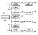
- FIG. 3is a schematic diagram illustrating the components of a power switch embodiment of the claimed invention.
- FIG. 4is a schematic diagram illustrating the components of another power switch embodiment of the claimed invention.
- any examples or illustrations given hereinare not to be regarded in any way as restrictions on, limits to, or express definitions of, any term or terms with which they are utilized. Instead these examples or illustrations are to be regarded as being described with respect to one particular embodiment and as illustrative only. Those of ordinary skill in the art will appreciate that any term or terms with which these examples or illustrations are utilized encompass other embodiments as well as implementations and adaptations thereof which may or may not be given therewith or elsewhere in the specification and all such embodiments are intended to be included within the scope of that term or terms.
- FIG. 1illustrates a conventional implementation of individual mode power switching.
- USB hub 100provides USB connectivity with peripheral devices via two USB ports, 105 and 110 .
- USB hub 100supports data and power transfers between the host device and peripheral USB devices via USB ports 105 and 110 .
- Data transfersare supported using individual pairs of D+ and D ⁇ lines that support USB connections at each of the USB ports 105 and 110 .
- Power transfers via the USB ports 105 and 110are supported by power switches 115 and 120 .
- the USB hub 100independently enables power transfers by USB ports 105 and 110 by signaling the respective power switches 115 and 120 via PRTPWR signal lines.
- USB hub 100has a dedicated power switch, allowing power transfers by each USB port to be independently controlled by USB hub 100 .
- power switches 115 and 120respectively protect USB ports 105 and 110 , and the peripheral devices connected to those ports, from over-current conditions that could potentially damage circuitry in the peripheral devices or the host device.
- both power switch 115 and power switch 120include over-current sensing circuitry that measures the current drawn by a USB port and determines whether the measured current draw exceeds a predetermined current limit for that USB port.
- each power switch 115 and 120operates independently. If the current sensing circuitry of power switch 115 detects a current draw by a peripheral device connected to USB port 105 that exceeds the current limit for that port, power switch 115 turns off power to USB port 105 .
- each power switchUpon detecting an over-current condition and switching off power to a USB port, each power switch signals this condition back to USB hub 100 via an Over Current Sensing (OCS) signal line.
- OCSOver Current Sensing
- USB limits for USB ports 105 and 110may be individually determined based on enumeration of the peripheral devices connected to each USB port. This ability to individually tailor current limit protection to each USB port based on the properties of the peripheral device connected to the port is a key benefit provided by individual mode power switching. However, as described above, this benefit comes at the cost required to include power switching and current sensing hardware for each USB port.
- USB hub 200enables power transfers by both USB ports 105 and 110 by signaling the power switch 215 via a PRTPWR signal line.
- USB ports 105 and 110share a single power switch and current sensing unit 215 . Consequently, power transfers by USB ports 105 and 110 are collectively controlled by the USB hub 100 .
- power switch 215protects USB ports 205 and 210 and the peripheral devices connected to those ports from over-current conditions that could potentially damage circuitry in the peripheral devices or the host device.
- Power switch 215includes over-current sensing circuitry that measures the total current collectively drawn by USB ports 205 and 210 and determines whether an over-current condition exists on either of these ports. As a gang mode power switch, power switch 215 provides collective over current protection to both USB ports 205 and 210 . If the current sensing circuitry of power switch 215 detects a total current draw by USB port 205 and USB port 210 that exceeds a specified current limit, power switch 215 turns off power delivery to both USB port 205 and USB port 210 . Upon detecting an over current condition and switching off power to both USB ports 205 and 210 , power switch 215 signals this over-current condition back to USB hub 200 via an OCS signal line.
- the current limit enforced by power switch 215 on both USB ports 205 and 210is typically determined based on enumeration of the peripheral devices connected to each of the USB ports. Based on enumeration of all connected peripheral devices, a single current limit that adequately protects all of the peripheral devices may be determined by the USB hub 200 . The current limit determined by USB hub 200 is communicated to power switch 215 , which enforces this current limit. Unlike an individual mode power switch, the gang mode power switch is unable to individually tailor current limit protection to each USB port. However, by utilizing a single power switch and current sensing unit, the gang mode power switch provides considerable cost savings compared to the individual mode power switch.
- FIG. 3illustrates an embodiment of a power switch that enables combining individual mode power switching and gang mode power switching in a manner that provides certain benefits provided by each of the two modes of over-current protection.
- over current protectionis provided for USB port 305 and USB port 350 using a single power switch 325 .
- a power port control logic unit 300controls power switch 325 .
- the power port control logic unitis a component of a USB hub or a USB power port controller.
- the power port control logic unit 300controls the state of power switch 325 based on whether the current drawn on either USB port 350 or USB port 305 has triggered a current limit threshold. Both USB port 350 and USB port 305 are independently monitored to detect whether peripheral devices connected to these ports are drawing current in excess of a current limit threshold.
- the current drawn by peripheral devices connected to either USB port 305 or USB port 350is measured using a current sensing unit and a shunt resistor. More specifically, the current drawn on USB port 305 is measured by current sensing unit 320 and shunt resistor 310 . The current sensing unit 320 calculates the current drawn on USB port 305 based on the measured voltage drop across shunt resistor 310 . Another current sensing unit 340 and shunt resistor 345 similarly determine the current drawn on USB port 350 . The current measurements generated by current sensing unit 320 are used to detect an over current condition on USB port 305 and the measurements generated by current sensing unit 340 are used to detect an over current condition on USB port 350 .
- a comparator componentis used to determine whether the current limit of a USB port has been exceeded.
- comparator 330receives the measured current drawn on USB port 305 , as measured by current sensing unit 320 .
- the comparator 330evaluates the value of the measured current against a current limit setting stored in a register 315 that is associated with USB port 305 . If the comparator 330 determines that the measured current exceeds the current limit setting for USB port 305 , the comparator 330 signals this condition to the power port control logic unit 300 .
- the port power control logic unit 300In response to the detection of this over-current condition on USB port 305 , the port power control logic unit 300 then signals power switch 325 to shut off power supplied to both USB port 305 and USB port 350 .
- Power port control logic unit 300similarly provides over-current protection based on current measurements made with respect USB port 350 .
- a shunt resistor 345 and current sensing unit 340are used to measure the current drawn on USB port 350 . These current measurements are evaluated against a current limit setting for USB port 350 by comparator 335 .
- Comparatorretrieves a current limit setting for USB port 350 from register 355 . Based on the current limit setting and the measured current, comparator 335 determines if an over-current condition is present in USB port 350 . If an over-current condition is detected, comparator 335 relays this information to power port control logic unit 300 . The same as for the detection of an over-current condition in USB port 305 , the power port control logic unit 300 responds to the over-current condition in USB port 350 by signaling power switch 325 to shut off power supplied to both USB port 305 and USB port 350 .
- the embodiment of FIG. 3utilizes a single power switch 325 to implement over-current protection for multiple USB ports while utilizing current sensing measurements and determinations that are individualized to each USB port.
- current limit settingsthat can be tailored to individual USB ports
- current limit evaluationscan be made while minimizing stress on the USB connectors that comprise the USB ports. Consequently, the embodiment of FIG. 3 provides the cost benefit of a gang mode power switch while still providing the reduced stress and more narrowly tailored over-current protection offered by an individual mode power switch.
- the current limit for each USB portmay be a fixed aspect of the comparator.
- the embodiment of FIG. 3utilizes registers 315 and 355 to store current limit settings for detecting over-current conditions in USB port 305 and 350 , respectively. These registers can be updated with updated current limit settings as needed. In some scenarios, the flexibility provided by these registers does not justify their extra cost. Instead, each comparator may instead utilize a fixed current limit setting.
- a single registermay be used to store a single current limit setting that is used by all comparators. In some scenarios, the same current limit may be used for over-current protection on all USB ports. This single current limit can be stored in a central register that is accessed by each of the comparators.
- FIG. 4illustrates an embodiment that provides over-current protection to four ganged USB ports using a port power control logic unit that is configured to serve as a central evaluator of current limit thresholds.
- Independent current sensingis provided for each of the four ganged USB ports 410 , 420 , 430 and 440 .
- current sensing on the power lines of each of the USB portsis independently implemented using current sensing components such as a shunt resistor and an associated current sensing unit.
- the current drawn by a peripheral device connected to USB port 410is determined by current sensing components 405 .
- Current sensingis likewise independently implemented for each of the remaining USB ports.
- Each current sensing unit 405 , 415 , 425 and 435output current measurements to a port power control logic unit 400 .
- the embodiment of FIG. 4utilizes a dedicated switchable power supply 445 to provide power to the supported USB ports.
- the power supply 445receives commands from power port control logic unit 400 . If an over-current condition is detected by power port control logic unit 400 , a command is dispatched ordering power supply 445 to shut off power to USB ports 410 , 420 , 430 and 440 . Replacing the power switch with a dedicated power supply 445 is particularly useful in systems comprised of self-contained and separately-powered components, such as automotive electronics.
- the port power logic control 400 unitis configured to serve as a comparator capable of evaluating whether current limit settings have been violated on any of the supported USB ports 410 , 420 , 430 , or 440 . Measurements made by the current sensing units 405 , 415 , 425 , and 435 are provided to the power logic control unit 400 which then compares the measurements to current limit settings retrieved from a set of current limit registers 450 . As with the embodiment of FIG. 3 , each of the supported USB ports 410 , 420 , 430 , or 440 will have a current limit stored in an associated register in the set of current limit registers 450 .
- one or more additional registersmay be present in the set of current limit registers 450 where these additional registers store current limits for evaluating the collective current draw by all the USB ports 410 , 420 , 430 , or 440 .
- the port power logic control unit 400is configured to compare the received current measurements against the associated current limit setting retrieved from one of the current limit registers 450 . If a current limit is violated, the port power control logic unit 400 signals the power supply 445 to shut off power to all USB ports.
- the port power logic control unitis 400 capable of making current limit determinations regarding both individual USB ports and aggregate use by all supported USB ports.
- the port power logic control unit 400is thus able to enforce current limits based on multiple conditions.
- the port power control logic unit 400implements both the individualized over-current protection provided by individual mode power switching and the collective protection provided by gang mode power switching.
- the port power control logicwill be further configured to serve as the current sensing unit, in addition to serving as a comparator.
- a shunt resistormay still be used to obtain voltage measurements that can be used to calculate the current draw by an individual USB port.
- the voltage measurements associated with each shunt resistorare inputs to the port power control logic unit.
- an input multiplexermay be used, with the multiplexer inputs receiving pairs of voltage measurements for each of the shunt resistors.
- the multiplexeris further configured to retrieve the current limit that is applicable to each pair of shunt resistor readings from registers that store current limits for the individual USB ports.
- the multiplexeris further configured to output each pair of voltage measurements to an analog-to-digital converter (ADC) that is configured as a current sensing unit.
- ADCanalog-to-digital converter
- the measurements made by the ADC and the retrieved current limitsare then used by the port power control logic unit to make over-current determinations.
- a port power control logic unitthat is configured in this manner is able to make individual over-current determinations for each USB port, as well as collective over-current determinations across all USB ports.
- USB portscan be divided into sub-groups, with each sub-group of USB ports sharing a single current sensing unit and a single comparator. In such instances, multiple USB ports can be protected collectively under a single current limit while remaining safely within the current ratings for the USB connectors used to implement each USB port.
- Each sub-group of USB portsis powered using a shared power rail. The current draw by an individual sub-group of USB ports is measured using a shunt resistor on power rail that is shared by the sub-group.
- current sensing components 405might measure the current drawn on USB ports 410 and 420 and current sensing components 425 might measure the current draw on USB ports 430 and 440 .
- the number of USB ports that may be ganged into such sub-groupscan be determined according to the current ratings of the USB connectors.
- the measurements for each sub-groupmay be evaluated using a dedicated current sensing unit and comparator that retrieves a current limit for the subgroup from a register.
- current sensingwill be implemented using an ADC that is configured to make over-current determinations for each individual sub-group of USB ports.
- the current measurements for all sub-groupsmay be centrally evaluated by the port power control logic unit.
- central over-current evaluation for all sub-groups of USB portsmay be implemented using an ADC and input multiplexer. Grouping the USB ports in this manner provides the cost benefit of reducing the number of current sensing and comparator units while still ensuring that USB connectors are not subjected to potentially damaging currents.
Landscapes
- Engineering & Computer Science (AREA)
- Theoretical Computer Science (AREA)
- General Engineering & Computer Science (AREA)
- Physics & Mathematics (AREA)
- General Physics & Mathematics (AREA)
- Computer Hardware Design (AREA)
- Computing Systems (AREA)
- Power Sources (AREA)
- Direct Current Feeding And Distribution (AREA)
Abstract
Description
- This application claims the benefit of U.S. Provisional Application No. 61/989,112 filed on May 6, 2014, which is incorporated herein in its entirety.
- The present disclosure relates to universal serial bus (USB) technology, in particular power switches for providing over-current protection on USB ports comprised in a USB hub.
- The Universal Serial Bus (USB) standard was developed to provide personal computer users with a single hardware and software interface for connecting a wide range of peripherals to desktop and laptop computers. USB has become the interface of choice for peripheral devices because it offers simple connectivity and a standardized interface that has proven effective for communicating with a vast array of peripheral devices. In addition to providing a standardized interface for communications between a peripheral device and a host device, USB provides the ability to transfer power bi-directionally via a USB connection.
- Building on advances in battery technology, peripheral devices powered at least in part by internal, rechargeable batteries have become common in the marketplace. USB has become a popular mechanism for charging these battery-powered peripheral devices. For many peripheral devices, USB is the sole interface provided for charging the peripheral's internal batteries. Some USB peripheral devices have no internal batteries and rely strictly on the power provided via a USB connection in order to operate.
- From a hardware perspective, host devices commonly provide a USB interface via a hub that typically has two or more USB ports. In general, a USB hub multiplies the number of USB ports that can be supported by a host device. Each of the USB ports supported by a hub is a “power port” that, in additional to supporting data transfers, also provides the capability of powering and/or charging a connected USB peripheral device. Certain USB ports are configured as dedicated charging ports that do not support data transfers and are strictly used for transferring power, making these ports especially adapted for charging the batteries of a peripheral USB device. Certain hubs include an internal power supply and are thus “self-powered.” Hubs that are self-powered must include over-current protection in order to limit the possibility of allowing potentially harmful current levels to be drawn by peripheral devices connected to the hub.
- In devices compliant with the USB standard, the amount of power that can be transferred via a USB connection is limited according to thresholds set forth in the USB specification and its revisions. In the first version of the USB standard, the amount of current that could be transferred via a USB connection was limited to 500 mA. This current limit for USB connection was later increased to 900 mA and then to 1.5 Å. The current limit for USB charging ports has recently been increased to 5 Å. In some cases, the maximum available current may be provided by a USB hub as soon as a peripheral device is connected to one of its USB ports. In most instances, however, enumeration of the peripheral device by the host device determines the appropriate current level that should be provided by the USB hub. The USB hardware of the host device must be capable of supporting these various current limit settings and providing a regulated supply of power that stays below the threshold current limit that is applicable for a USB port at any given time.
- USB hubs implement power switching circuitry that is configured to enforce the applicable current limits on the USB ports that are supported by a hub. In general, power switching turns off the power supplied to a USB port when the current drawn by a peripheral device connected to the USB port exceeds a current limit. Two different mechanisms may be used by USB hubs to implement power switching.
- Individual mode power switching implements a dedicated power switching mechanism for each USB port. Each USB port has an individual power switching mechanism that measures the current drawn by a peripheral device connected to the USB port and shuts off power provided by the port's USB connection if the measured current draw exceeds the current limit that is being enforced for this port.
- The second power switching mechanism is gang mode power switching, where the USB hub regulates and controls power to a group of USB ports on a collective basis. In ganged mode power switching, the USB hub measures the total current that is collectively drawn by the peripheral devices connected to the ganged USB ports. If the measured, aggregate current drawn by the ganged USB ports exceeds the current limit being enforced, the USB hub shuts off power to all of the ganged USB ports.
- With regards to the cost required to implement over current protection, gang mode power switching is preferable to individual mode switching since implementing a gang mode power switch requires only a single power switch and a single current sensing component that measures the current being drawn by all ports, while individual mode requires a separate power switch and current sensing component for every USB port. Despite the cost savings provided by gang mode power switching, as USB charging ports become more prevalent and the current limits being supported by USB ports increase, gang mode power switches place greater demands on the USB connectors used to deliver this power.
- In particular, implementing gang mode power switching requires that the USB connectors that comprise each of the USB ports withstand currents up to the current limit being enforced by the single power switch and current sensing component. Since the current limit used by a gang mode power switch will typically be compared to the sum of the current draws on all of the supported USB ports, this current limit is typically set as high as possible in order to support simultaneous current draws on the supported USB ports. Moreover, the current limits that must be supported by USB power port switches have gradually increased as the current draws supported by USB have been increased. However, many USB connectors presently being sold were originally designed for use at the lower current levels in use prior to changes in the USB standard. As a result, USB connector components used in gang mode power switches may be exposed to current levels that exceed the current ratings for the USB connectors, thus stressing these components and increasing malfunctions and failures.
- Individual power mode switching places less stress on the USB connectors since each USB port has a dedicated power switch and current sensing unit that is configured to protect an individual USB port. This allows the current limit settings in individual mode power switches to be set according to the current rating of the connector hardware of the individual USB port being protected and the properties of the peripheral device connected to the USB port, without concern for providing sufficient current for multiple USB ports to operate concurrently. Thus, there exists a need for USB power switching that can provide the costs benefits of gang mode power switching while providing the reduced stress on USB connectors and individualized protection that is provided by individual mode power switching.
- Conventional power switches must choose between the advantages and disadvantages of individual mode power switching and ganged mode power switching. Hence, there is a need for a power switch that can provide certain of benefits provided by both modes of power switching. This is achieved through embodiments of the present invention.
- According to an embodiment, a USB hub includes a plurality of USB ports, a power element for providing a supply of current to the plurality of USB ports, a plurality of current measurement units and a power port control logic unit. The plurality of current measurement units measure the current drawn by a USB port sub-group. A USB port sub-group is comprised of one or more of the plurality of USB ports. The power port control logic unit is configured to control the power element. The power port control logic unit receives one or more current measurements from the plurality of current measurement units and is configured to direct the power element to turn off the supply of current to the plurality of USB ports if the received current measurements indicate a current limit has been exceeded by one or more of the USB port sub-groups.
- According to further embodiments, the power element is a power switch or a controllable power supply. According to further embodiments, each of the current measurement units comprises a shunt resistor and a current sensing unit. Further embodiments include a plurality of registers, wherein each of the plurality of registers stores a current limit for each USB port sub-group. Further embodiments include a comparator configured to retrieve one or more current limits from the plurality of registers and further configured to determine whether one or more of the current measurements exceed one or more of the retrieved current limits. According to further embodiments, the current measurement unit comprises an analog-to-digital converter. According to further embodiments, the power port control logic unit is further configured to sum the received current measurements to determine the aggregate current drawn by all USB port sub-groups and the power port control logic unit is further configured to determine if the aggregate current drawn by all USB port sub-groups exceeds a current limit.
- The present invention may be better understood, and its numerous objects, features, and advantages made apparent to those skilled in the art, by referencing the accompanying drawings. The use of the same reference symbols in different drawings indicates similar or identical items.
FIG. 1 is a schematic diagram illustrating the components of a conventional individual mode power switchFIG. 2 is a schematic diagram illustrating the components of a conventional gang mode power switch.FIG. 3 is a schematic diagram illustrating the components of a power switch embodiment of the claimed invention.FIG. 4 is a schematic diagram illustrating the components of another power switch embodiment of the claimed invention.- The disclosure and various features and advantageous details thereof are explained more fully with reference to the exemplary, and therefore non-limiting, embodiments illustrated in the accompanying drawings and detailed in the following description. Descriptions of known programming techniques, computer software, hardware, operating platforms and protocols may be omitted so as not to unnecessarily obscure the disclosure in detail. It should be understood, however, that the detailed description and the specific examples, while indicating the preferred embodiments, are given by way of illustration only and not by way of limitation. Various substitutions, modifications, additions and/or rearrangements within the spirit and/or scope of the underlying inventive concept will become apparent to those skilled in the art from this disclosure.
- Additionally, any examples or illustrations given herein are not to be regarded in any way as restrictions on, limits to, or express definitions of, any term or terms with which they are utilized. Instead these examples or illustrations are to be regarded as being described with respect to one particular embodiment and as illustrative only. Those of ordinary skill in the art will appreciate that any term or terms with which these examples or illustrations are utilized encompass other embodiments as well as implementations and adaptations thereof which may or may not be given therewith or elsewhere in the specification and all such embodiments are intended to be included within the scope of that term or terms.
FIG. 1 illustrates a conventional implementation of individual mode power switching. In the power switch implementation ofFIG. 1 ,USB hub 100 provides USB connectivity with peripheral devices via two USB ports,105 and110. On behalf a host device,USB hub 100 supports data and power transfers between the host device and peripheral USB devices viaUSB ports USB ports USB ports power switches USB hub 100 independently enables power transfers byUSB ports respective power switches FIG. 1 has a dedicated power switch, allowing power transfers by each USB port to be independently controlled byUSB hub 100. In addition to supplying theUSB ports USB ports - In providing individual current protection to each of the
USB ports power switch 115 andpower switch 120 include over-current sensing circuitry that measures the current drawn by a USB port and determines whether the measured current draw exceeds a predetermined current limit for that USB port. As an individual mode power switch implementation, eachpower switch power switch 115 detects a current draw by a peripheral device connected toUSB port 105 that exceeds the current limit for that port,power switch 115 turns off power toUSB port 105. Upon detecting an over-current condition and switching off power to a USB port, each power switch signals this condition back toUSB hub 100 via an Over Current Sensing (OCS) signal line. Current limits forUSB ports FIG. 2 illustrates a conventional implementation of gang mode power switching. In this power switch implementation,USB hub 200 supports USB connections with peripheral devices viaUSB ports USB hub 200 supports data and power transfers between a host device and peripheral USB devices viaUSB ports USB ports - Unlike the individual mode power switch, power transfers via
USB ports single power switch 215 in the gang mode power switch ofFIG. 2 .USB hub 200 enables power transfers by bothUSB ports power switch 215 via a PRTPWR signal line. As an implementation of a gang mode power switch,USB ports current sensing unit 215. Consequently, power transfers byUSB ports USB hub 100. As with the individual mode power switch ofFIG. 1 ,power switch 215 protectsUSB ports Power switch 215 includes over-current sensing circuitry that measures the total current collectively drawn byUSB ports power switch 215 provides collective over current protection to bothUSB ports power switch 215 detects a total current draw byUSB port 205 andUSB port 210 that exceeds a specified current limit,power switch 215 turns off power delivery to bothUSB port 205 andUSB port 210. Upon detecting an over current condition and switching off power to bothUSB ports power switch 215 signals this over-current condition back toUSB hub 200 via an OCS signal line.- The current limit enforced by
power switch 215 on bothUSB ports USB hub 200. The current limit determined byUSB hub 200 is communicated topower switch 215, which enforces this current limit. Unlike an individual mode power switch, the gang mode power switch is unable to individually tailor current limit protection to each USB port. However, by utilizing a single power switch and current sensing unit, the gang mode power switch provides considerable cost savings compared to the individual mode power switch. FIG. 3 illustrates an embodiment of a power switch that enables combining individual mode power switching and gang mode power switching in a manner that provides certain benefits provided by each of the two modes of over-current protection. In the embodiment illustrated inFIG. 3 , over current protection is provided forUSB port 305 andUSB port 350 using asingle power switch 325. A power portcontrol logic unit 300 controlspower switch 325. In some embodiments, the power port control logic unit is a component of a USB hub or a USB power port controller. The power portcontrol logic unit 300 controls the state ofpower switch 325 based on whether the current drawn on eitherUSB port 350 orUSB port 305 has triggered a current limit threshold. BothUSB port 350 andUSB port 305 are independently monitored to detect whether peripheral devices connected to these ports are drawing current in excess of a current limit threshold.- In the embodiment of
FIG. 3 , the current drawn by peripheral devices connected to eitherUSB port 305 orUSB port 350 is measured using a current sensing unit and a shunt resistor. More specifically, the current drawn onUSB port 305 is measured bycurrent sensing unit 320 andshunt resistor 310. Thecurrent sensing unit 320 calculates the current drawn onUSB port 305 based on the measured voltage drop acrossshunt resistor 310. Anothercurrent sensing unit 340 andshunt resistor 345 similarly determine the current drawn onUSB port 350. The current measurements generated bycurrent sensing unit 320 are used to detect an over current condition onUSB port 305 and the measurements generated bycurrent sensing unit 340 are used to detect an over current condition onUSB port 350. - In order to determine whether current limits have been exceeded in either of the USB ports, the current measurements made by the current sensing unit are compared to current limit values that have been individually specified for each of the USB ports. In some embodiments, a comparator component is used to determine whether the current limit of a USB port has been exceeded. In the embodiment of
FIG. 3 ,comparator 330 receives the measured current drawn onUSB port 305, as measured bycurrent sensing unit 320. Thecomparator 330 evaluates the value of the measured current against a current limit setting stored in aregister 315 that is associated withUSB port 305. If thecomparator 330 determines that the measured current exceeds the current limit setting forUSB port 305, thecomparator 330 signals this condition to the power portcontrol logic unit 300. In response to the detection of this over-current condition onUSB port 305, the port powercontrol logic unit 300 then signalspower switch 325 to shut off power supplied to bothUSB port 305 andUSB port 350. - Power port
control logic unit 300 similarly provides over-current protection based on current measurements made withrespect USB port 350. Ashunt resistor 345 andcurrent sensing unit 340 are used to measure the current drawn onUSB port 350. These current measurements are evaluated against a current limit setting forUSB port 350 bycomparator 335. Comparator retrieves a current limit setting forUSB port 350 fromregister 355. Based on the current limit setting and the measured current,comparator 335 determines if an over-current condition is present inUSB port 350. If an over-current condition is detected,comparator 335 relays this information to power portcontrol logic unit 300. The same as for the detection of an over-current condition inUSB port 305, the power portcontrol logic unit 300 responds to the over-current condition inUSB port 350 by signalingpower switch 325 to shut off power supplied to bothUSB port 305 andUSB port 350. - In this manner, the embodiment of
FIG. 3 utilizes asingle power switch 325 to implement over-current protection for multiple USB ports while utilizing current sensing measurements and determinations that are individualized to each USB port. By supporting current limit settings that can be tailored to individual USB ports, current limit evaluations can be made while minimizing stress on the USB connectors that comprise the USB ports. Consequently, the embodiment ofFIG. 3 provides the cost benefit of a gang mode power switch while still providing the reduced stress and more narrowly tailored over-current protection offered by an individual mode power switch. - In some embodiments, the current limit for each USB port may be a fixed aspect of the comparator. The embodiment of
FIG. 3 utilizesregisters USB port FIG. 4 illustrates an embodiment that provides over-current protection to four ganged USB ports using a port power control logic unit that is configured to serve as a central evaluator of current limit thresholds. Independent current sensing is provided for each of the four gangedUSB ports FIG. 3 , current sensing on the power lines of each of the USB ports is independently implemented using current sensing components such as a shunt resistor and an associated current sensing unit. The current drawn by a peripheral device connected toUSB port 410 is determined bycurrent sensing components 405. Current sensing is likewise independently implemented for each of the remaining USB ports. Eachcurrent sensing unit control logic unit 400.- Rather than utilize a power switch, the embodiment of
FIG. 4 utilizes a dedicatedswitchable power supply 445 to provide power to the supported USB ports. As with the power switch of the embodiment ofFIG. 3 , thepower supply 445 receives commands from power portcontrol logic unit 400. If an over-current condition is detected by power portcontrol logic unit 400, a command is dispatched orderingpower supply 445 to shut off power toUSB ports dedicated power supply 445 is particularly useful in systems comprised of self-contained and separately-powered components, such as automotive electronics. - In the embodiment of
FIG. 4 , the portpower logic control 400 unit is configured to serve as a comparator capable of evaluating whether current limit settings have been violated on any of the supportedUSB ports current sensing units logic control unit 400 which then compares the measurements to current limit settings retrieved from a set of current limit registers450. As with the embodiment ofFIG. 3 , each of the supportedUSB ports USB ports logic control unit 400 is configured to compare the received current measurements against the associated current limit setting retrieved from one of the current limit registers450. If a current limit is violated, the port powercontrol logic unit 400 signals thepower supply 445 to shut off power to all USB ports. - Configured in this manner, the port power logic control unit is400 capable of making current limit determinations regarding both individual USB ports and aggregate use by all supported USB ports. The port power
logic control unit 400 is thus able to enforce current limits based on multiple conditions. The port powercontrol logic unit 400 implements both the individualized over-current protection provided by individual mode power switching and the collective protection provided by gang mode power switching. - In some embodiments, the port power control logic will be further configured to serve as the current sensing unit, in addition to serving as a comparator. In such embodiments, a shunt resistor may still be used to obtain voltage measurements that can be used to calculate the current draw by an individual USB port. The voltage measurements associated with each shunt resistor are inputs to the port power control logic unit. In some embodiments an input multiplexer may be used, with the multiplexer inputs receiving pairs of voltage measurements for each of the shunt resistors. The multiplexer is further configured to retrieve the current limit that is applicable to each pair of shunt resistor readings from registers that store current limits for the individual USB ports. The multiplexer is further configured to output each pair of voltage measurements to an analog-to-digital converter (ADC) that is configured as a current sensing unit. The measurements made by the ADC and the retrieved current limits are then used by the port power control logic unit to make over-current determinations. As described above, a port power control logic unit that is configured in this manner is able to make individual over-current determinations for each USB port, as well as collective over-current determinations across all USB ports.
- In some embodiments, USB ports can be divided into sub-groups, with each sub-group of USB ports sharing a single current sensing unit and a single comparator. In such instances, multiple USB ports can be protected collectively under a single current limit while remaining safely within the current ratings for the USB connectors used to implement each USB port. Each sub-group of USB ports is powered using a shared power rail. The current draw by an individual sub-group of USB ports is measured using a shunt resistor on power rail that is shared by the sub-group. For instance, in a modification of the embodiment of
FIG. 4 ,current sensing components 405 might measure the current drawn onUSB ports current sensing components 425 might measure the current draw onUSB ports - According to the various embodiments, the measurements for each sub-group may be evaluated using a dedicated current sensing unit and comparator that retrieves a current limit for the subgroup from a register. For instance, in some embodiments, current sensing will be implemented using an ADC that is configured to make over-current determinations for each individual sub-group of USB ports. According to other embodiments, the current measurements for all sub-groups may be centrally evaluated by the port power control logic unit. As described, central over-current evaluation for all sub-groups of USB ports may be implemented using an ADC and input multiplexer. Grouping the USB ports in this manner provides the cost benefit of reducing the number of current sensing and comparator units while still ensuring that USB connectors are not subjected to potentially damaging currents.
Claims (20)
Priority Applications (2)
| Application Number | Priority Date | Filing Date | Title |
|---|---|---|---|
| US14/701,854US9715271B2 (en) | 2014-05-06 | 2015-05-01 | USB power port control |
| TW104114488ATWI660266B (en) | 2014-05-06 | 2015-05-06 | Usb power port control |
Applications Claiming Priority (2)
| Application Number | Priority Date | Filing Date | Title |
|---|---|---|---|
| US201461989112P | 2014-05-06 | 2014-05-06 | |
| US14/701,854US9715271B2 (en) | 2014-05-06 | 2015-05-01 | USB power port control |
Publications (2)
| Publication Number | Publication Date |
|---|---|
| US20150323979A1true US20150323979A1 (en) | 2015-11-12 |
| US9715271B2 US9715271B2 (en) | 2017-07-25 |
Family
ID=53274796
Family Applications (1)
| Application Number | Title | Priority Date | Filing Date |
|---|---|---|---|
| US14/701,854Active2035-07-02US9715271B2 (en) | 2014-05-06 | 2015-05-01 | USB power port control |
Country Status (6)
| Country | Link |
|---|---|
| US (1) | US9715271B2 (en) |
| EP (1) | EP3140712B1 (en) |
| KR (1) | KR20170003523A (en) |
| CN (1) | CN106164813A (en) |
| TW (1) | TWI660266B (en) |
| WO (1) | WO2015171463A1 (en) |
Cited By (14)
| Publication number | Priority date | Publication date | Assignee | Title |
|---|---|---|---|---|
| US20160179155A1 (en)* | 2014-12-23 | 2016-06-23 | Intel Corporation | Apparatus and Methods for Power Conflict Resolution in Power Delivery Systems |
| US9766675B2 (en)* | 2015-12-04 | 2017-09-19 | Intel Corporation | Methods and apparatuses to provide power in idle states |
| US10641811B2 (en) | 2016-06-16 | 2020-05-05 | Samsung Electronics Co., Ltd. | Method for detecting leakage current and electronic device supporting the same |
| US10955865B1 (en)* | 2020-01-22 | 2021-03-23 | Cypress Semiconductor Corporation | Firmware-controlled cable drop voltage compensation |
| US10996729B2 (en)* | 2016-07-12 | 2021-05-04 | Hewlett-Packard Development Company, L.P. | Balancing a power load among USB ports |
| DE102019134551A1 (en)* | 2019-12-16 | 2021-06-17 | Fujitsu Client Computing Limited | Interface arrangement, computer system and method |
| US11175722B2 (en)* | 2017-04-20 | 2021-11-16 | Hewlett-Packard Development Company, L.P. | Computing device power management |
| WO2022050933A1 (en)* | 2020-09-01 | 2022-03-10 | Hewlett-Packard Development Company, L.P. | Power supplied to ports based on charge amounts |
| US11385696B2 (en)* | 2017-12-11 | 2022-07-12 | Canon Kabushiki Kaisha | Electronic apparatus, control method in electronic apparatus, and apparatus |
| WO2022208286A1 (en)* | 2021-03-30 | 2022-10-06 | Cilag Gmbh International | Intelligent data ports for modular energy systems |
| WO2022208309A3 (en)* | 2021-03-30 | 2022-11-10 | Cilag Gmbh International | Method for intelligent instruments for modular energy system |
| WO2024010519A1 (en)* | 2022-07-08 | 2024-01-11 | Razer (Asia-Pacific) Pte. Ltd. | A bus powered device |
| US12012089B2 (en)* | 2021-09-23 | 2024-06-18 | Ford Global Technologies, Llc | Auxiliary device power testing for vehicle power delivery |
| US12292774B2 (en)* | 2016-03-15 | 2025-05-06 | Roku, Inc. | Brown out condition detection and device calibration |
Families Citing this family (33)
| Publication number | Priority date | Publication date | Assignee | Title |
|---|---|---|---|---|
| EP3208684A1 (en)* | 2016-02-16 | 2017-08-23 | Teleplan Technology B.V. | Mobile device testing apparatus and method |
| US10976798B2 (en) | 2016-11-30 | 2021-04-13 | Trane International Inc. | Automated peripheral power management |
| EP3563211B1 (en)* | 2016-12-30 | 2022-11-09 | The Wiremold Company | Power distribution system |
| KR101953302B1 (en)* | 2017-08-30 | 2019-02-28 | 한국전력기술 주식회사 | USB security device using crank type bi-directional USB socket |
| JP7081294B2 (en)* | 2018-05-11 | 2022-06-07 | トヨタ自動車株式会社 | Electronic unit |
| US11804679B2 (en) | 2018-09-07 | 2023-10-31 | Cilag Gmbh International | Flexible hand-switch circuit |
| US11510720B2 (en) | 2018-09-07 | 2022-11-29 | Cilag Gmbh International | Managing simultaneous monopolar outputs using duty cycle and synchronization |
| US20200078113A1 (en) | 2018-09-07 | 2020-03-12 | Ethicon Llc | Port presence detection system for modular energy system |
| US11923084B2 (en) | 2018-09-07 | 2024-03-05 | Cilag Gmbh International | First and second communication protocol arrangement for driving primary and secondary devices through a single port |
| US12144136B2 (en) | 2018-09-07 | 2024-11-12 | Cilag Gmbh International | Modular surgical energy system with module positional awareness with digital logic |
| US10976351B2 (en)* | 2019-02-12 | 2021-04-13 | Nxp B.V. | Current monitoring device |
| US11218822B2 (en) | 2019-03-29 | 2022-01-04 | Cilag Gmbh International | Audio tone construction for an energy module of a modular energy system |
| US11729643B2 (en)* | 2019-04-26 | 2023-08-15 | Kyocera Document Solutions Inc. | Communication device and image forming apparatus |
| USD939545S1 (en) | 2019-09-05 | 2021-12-28 | Cilag Gmbh International | Display panel or portion thereof with graphical user interface for energy module |
| EP4148535A1 (en)* | 2020-06-09 | 2023-03-15 | TQ-Systems GmbH | Power management and distribution device |
| US12235697B2 (en) | 2021-03-30 | 2025-02-25 | Cilag Gmbh International | Backplane connector attachment mechanism for modular energy system |
| US11978554B2 (en) | 2021-03-30 | 2024-05-07 | Cilag Gmbh International | Radio frequency identification token for wireless surgical instruments |
| US11950860B2 (en) | 2021-03-30 | 2024-04-09 | Cilag Gmbh International | User interface mitigation techniques for modular energy systems |
| US11857252B2 (en) | 2021-03-30 | 2024-01-02 | Cilag Gmbh International | Bezel with light blocking features for modular energy system |
| US12004824B2 (en) | 2021-03-30 | 2024-06-11 | Cilag Gmbh International | Architecture for modular energy system |
| US11980411B2 (en) | 2021-03-30 | 2024-05-14 | Cilag Gmbh International | Header for modular energy system |
| US12369994B2 (en) | 2021-03-30 | 2025-07-29 | Cilag Gmbh International | Modular energy system with multi-energy port splitter for multiple energy devices |
| US12228987B2 (en) | 2021-03-30 | 2025-02-18 | Cilag Gmbh International | Method for energy delivery for modular energy system |
| US11968776B2 (en) | 2021-03-30 | 2024-04-23 | Cilag Gmbh International | Method for mechanical packaging for modular energy system |
| US12040749B2 (en) | 2021-03-30 | 2024-07-16 | Cilag Gmbh International | Modular energy system with dual amplifiers and techniques for updating parameters thereof |
| US11963727B2 (en) | 2021-03-30 | 2024-04-23 | Cilag Gmbh International | Method for system architecture for modular energy system |
| US20220331051A1 (en) | 2021-04-14 | 2022-10-20 | Cilag Gmbh International | Utilizing contextual parameters of one or more surgical devices to predict a frequency interval for displaying surgical information |
| EP4318230A4 (en) | 2021-05-12 | 2024-08-07 | Samsung Electronics Co., Ltd. | ELECTRONIC DEVICE COMPRISING A USB CONNECTION TERMINAL AND METHOD OF OPERATING THE SAME |
| KR20220153910A (en)* | 2021-05-12 | 2022-11-21 | 삼성전자주식회사 | Electronic device including usb connecting terminal and method of operation therof |
| TWI806093B (en)* | 2021-07-12 | 2023-06-21 | 致伸科技股份有限公司 | Calibration method for current detection and current protection mechanism and calibration device using the same |
| US12079460B2 (en) | 2022-06-28 | 2024-09-03 | Cilag Gmbh International | Profiles for modular energy system |
| TWI817794B (en)* | 2022-10-27 | 2023-10-01 | 宏碁股份有限公司 | Usb hub and operation method thereof |
| KR102853660B1 (en)* | 2024-03-25 | 2025-09-01 | 엘지전자 주식회사 | Electronic device |
Citations (17)
| Publication number | Priority date | Publication date | Assignee | Title |
|---|---|---|---|---|
| US4004201A (en)* | 1975-08-25 | 1977-01-18 | General Electric Company | Multi-function solid state trip unit with trip indicating means |
| US6000042A (en)* | 1997-08-25 | 1999-12-07 | 3Com Corporation | Fault detection on a dual supply system for a universal serial bus system |
| US6222716B1 (en)* | 1999-03-29 | 2001-04-24 | Justin Chiang | Power line protection devices and methods for providing overload protection to multiple outputs |
| US20020002593A1 (en)* | 1996-07-23 | 2002-01-03 | Ewing Carrel W. | Vertical-mount electrical power distribution plugstrip |
| US20060117195A1 (en)* | 2003-08-28 | 2006-06-01 | Fujitsu Limited | Host apparatus, device, and method for controlling communication system |
| US20070035271A1 (en)* | 2005-08-10 | 2007-02-15 | Quirion Jean P | Method and apparatus for detecting multiple overcurrent thresholds using a single comparator device |
| US20080019068A1 (en)* | 2002-05-06 | 2008-01-24 | Reynolds Gregory A | Current protection apparatus and method |
| US20080249666A1 (en)* | 2007-04-04 | 2008-10-09 | Buterbaugh Jerrod K | Dynamically Configuring Overcurrent Protection In A Power Supply |
| US20090100275A1 (en)* | 2007-10-15 | 2009-04-16 | Ray Chang | Dynamic port power allocation apparatus and methods |
| US7525291B1 (en)* | 2003-01-21 | 2009-04-28 | Microsemi Corporation | Linearly regulated battery charger |
| US20100235655A1 (en)* | 2009-01-13 | 2010-09-16 | Tauscher Brian E | Method and apparatus for implementing a limited functionality embedded universal serial bus (USB) host controller on a fully functional downstream USB port |
| US20110018344A1 (en)* | 2009-07-24 | 2011-01-27 | Hon Hai Precision Industry Co., Ltd. | Electronic device and method for dynamic usb power assignment |
| US20110298576A1 (en)* | 2010-06-08 | 2011-12-08 | Eaton Industries Gmbh | Tripping unit for circuit breaker |
| US20120080940A1 (en)* | 2010-10-01 | 2012-04-05 | The Boeing Company | Load Coordinating Power Draw for Limited Ampacity Circuits |
| US20120198119A1 (en)* | 2011-01-31 | 2012-08-02 | Bretford Manufacturing, Inc. | High Current Multi-Port USB Hub |
| US20140129856A1 (en)* | 2012-10-31 | 2014-05-08 | Thomson Licensing | Device and method for electric power management of a plurality of peripheral interfaces |
| US9229514B2 (en)* | 2010-01-29 | 2016-01-05 | Hewlett Parkard Enterprise Development LP | Managing electric energy distribution to multiple loads using selective capping |
Family Cites Families (9)
| Publication number | Priority date | Publication date | Assignee | Title |
|---|---|---|---|---|
| US6541879B1 (en) | 2001-03-23 | 2003-04-01 | Cypress Semiconductor Corp. | USB hub power management |
| DE602005016241D1 (en)* | 2004-05-19 | 2009-10-08 | Clipsal Asia Holdings Ltd | POWER CONTROL DEVICE |
| TWI272495B (en)* | 2005-04-14 | 2007-02-01 | Richtek Technology Corp | Configuration device and method for current output at USB port |
| JP4488987B2 (en)* | 2005-09-08 | 2010-06-23 | シャープ株式会社 | Control system, electronic device, and image forming apparatus |
| JP2009176152A (en)* | 2008-01-25 | 2009-08-06 | Sony Corp | Information processing apparatus |
| US8352758B2 (en)* | 2010-03-22 | 2013-01-08 | International Business Machines Corporation | Power bus current bounding using local current-limiting soft-switches and device requirements information |
| JP5901241B2 (en)* | 2011-11-18 | 2016-04-06 | キヤノン株式会社 | USB hub device and system using the same |
| CN103178418A (en)* | 2011-12-26 | 2013-06-26 | 鸿富锦精密工业(深圳)有限公司 | USB (Universal Serial Bus) hub |
| CN102857719B (en)* | 2012-09-12 | 2016-08-24 | 四川迪佳通电子有限公司 | A kind of electric power supply control system and method |
- 2015
- 2015-05-01CNCN201580019256.XApatent/CN106164813A/enactivePending
- 2015-05-01KRKR1020167025366Apatent/KR20170003523A/ennot_activeWithdrawn
- 2015-05-01WOPCT/US2015/028878patent/WO2015171463A1/enactiveApplication Filing
- 2015-05-01EPEP15725915.1Apatent/EP3140712B1/enactiveActive
- 2015-05-01USUS14/701,854patent/US9715271B2/enactiveActive
- 2015-05-06TWTW104114488Apatent/TWI660266B/enactive
Patent Citations (17)
| Publication number | Priority date | Publication date | Assignee | Title |
|---|---|---|---|---|
| US4004201A (en)* | 1975-08-25 | 1977-01-18 | General Electric Company | Multi-function solid state trip unit with trip indicating means |
| US20020002593A1 (en)* | 1996-07-23 | 2002-01-03 | Ewing Carrel W. | Vertical-mount electrical power distribution plugstrip |
| US6000042A (en)* | 1997-08-25 | 1999-12-07 | 3Com Corporation | Fault detection on a dual supply system for a universal serial bus system |
| US6222716B1 (en)* | 1999-03-29 | 2001-04-24 | Justin Chiang | Power line protection devices and methods for providing overload protection to multiple outputs |
| US20080019068A1 (en)* | 2002-05-06 | 2008-01-24 | Reynolds Gregory A | Current protection apparatus and method |
| US7525291B1 (en)* | 2003-01-21 | 2009-04-28 | Microsemi Corporation | Linearly regulated battery charger |
| US20060117195A1 (en)* | 2003-08-28 | 2006-06-01 | Fujitsu Limited | Host apparatus, device, and method for controlling communication system |
| US20070035271A1 (en)* | 2005-08-10 | 2007-02-15 | Quirion Jean P | Method and apparatus for detecting multiple overcurrent thresholds using a single comparator device |
| US20080249666A1 (en)* | 2007-04-04 | 2008-10-09 | Buterbaugh Jerrod K | Dynamically Configuring Overcurrent Protection In A Power Supply |
| US20090100275A1 (en)* | 2007-10-15 | 2009-04-16 | Ray Chang | Dynamic port power allocation apparatus and methods |
| US20100235655A1 (en)* | 2009-01-13 | 2010-09-16 | Tauscher Brian E | Method and apparatus for implementing a limited functionality embedded universal serial bus (USB) host controller on a fully functional downstream USB port |
| US20110018344A1 (en)* | 2009-07-24 | 2011-01-27 | Hon Hai Precision Industry Co., Ltd. | Electronic device and method for dynamic usb power assignment |
| US9229514B2 (en)* | 2010-01-29 | 2016-01-05 | Hewlett Parkard Enterprise Development LP | Managing electric energy distribution to multiple loads using selective capping |
| US20110298576A1 (en)* | 2010-06-08 | 2011-12-08 | Eaton Industries Gmbh | Tripping unit for circuit breaker |
| US20120080940A1 (en)* | 2010-10-01 | 2012-04-05 | The Boeing Company | Load Coordinating Power Draw for Limited Ampacity Circuits |
| US20120198119A1 (en)* | 2011-01-31 | 2012-08-02 | Bretford Manufacturing, Inc. | High Current Multi-Port USB Hub |
| US20140129856A1 (en)* | 2012-10-31 | 2014-05-08 | Thomson Licensing | Device and method for electric power management of a plurality of peripheral interfaces |
Non-Patent Citations (1)
| Title |
|---|
| Semig, Pete, and Collin Wells. "A Current Sensing Tutorial--Part 1: Fundamentals | EE Times." EETimes. Aspencore's Media Brands, 8 Feb. 2012. Web. 23 Aug. 2016. <http://www.eetimes.com/document.asp?doc_id=1279404>.* |
Cited By (17)
| Publication number | Priority date | Publication date | Assignee | Title |
|---|---|---|---|---|
| US20160179155A1 (en)* | 2014-12-23 | 2016-06-23 | Intel Corporation | Apparatus and Methods for Power Conflict Resolution in Power Delivery Systems |
| US9874913B2 (en)* | 2014-12-23 | 2018-01-23 | Intel Corporation | Apparatus and methods for power conflict resolution in power delivery systems |
| US9766675B2 (en)* | 2015-12-04 | 2017-09-19 | Intel Corporation | Methods and apparatuses to provide power in idle states |
| TWI721027B (en)* | 2015-12-04 | 2021-03-11 | 美商英特爾公司 | Methods and apparatuses to provide power in idle states |
| US12292774B2 (en)* | 2016-03-15 | 2025-05-06 | Roku, Inc. | Brown out condition detection and device calibration |
| US10641811B2 (en) | 2016-06-16 | 2020-05-05 | Samsung Electronics Co., Ltd. | Method for detecting leakage current and electronic device supporting the same |
| US10996729B2 (en)* | 2016-07-12 | 2021-05-04 | Hewlett-Packard Development Company, L.P. | Balancing a power load among USB ports |
| US11175722B2 (en)* | 2017-04-20 | 2021-11-16 | Hewlett-Packard Development Company, L.P. | Computing device power management |
| US11385696B2 (en)* | 2017-12-11 | 2022-07-12 | Canon Kabushiki Kaisha | Electronic apparatus, control method in electronic apparatus, and apparatus |
| DE102019134551A1 (en)* | 2019-12-16 | 2021-06-17 | Fujitsu Client Computing Limited | Interface arrangement, computer system and method |
| DE102019134551B4 (en) | 2019-12-16 | 2024-06-20 | Fujitsu Client Computing Limited | Interface arrangement, computer system and method |
| US10955865B1 (en)* | 2020-01-22 | 2021-03-23 | Cypress Semiconductor Corporation | Firmware-controlled cable drop voltage compensation |
| WO2022050933A1 (en)* | 2020-09-01 | 2022-03-10 | Hewlett-Packard Development Company, L.P. | Power supplied to ports based on charge amounts |
| WO2022208286A1 (en)* | 2021-03-30 | 2022-10-06 | Cilag Gmbh International | Intelligent data ports for modular energy systems |
| WO2022208309A3 (en)* | 2021-03-30 | 2022-11-10 | Cilag Gmbh International | Method for intelligent instruments for modular energy system |
| US12012089B2 (en)* | 2021-09-23 | 2024-06-18 | Ford Global Technologies, Llc | Auxiliary device power testing for vehicle power delivery |
| WO2024010519A1 (en)* | 2022-07-08 | 2024-01-11 | Razer (Asia-Pacific) Pte. Ltd. | A bus powered device |
Also Published As
| Publication number | Publication date |
|---|---|
| CN106164813A (en) | 2016-11-23 |
| KR20170003523A (en) | 2017-01-09 |
| US9715271B2 (en) | 2017-07-25 |
| TWI660266B (en) | 2019-05-21 |
| EP3140712A1 (en) | 2017-03-15 |
| WO2015171463A1 (en) | 2015-11-12 |
| TW201606493A (en) | 2016-02-16 |
| EP3140712B1 (en) | 2022-04-06 |
Similar Documents
| Publication | Publication Date | Title |
|---|---|---|
| US9715271B2 (en) | USB power port control | |
| US10983152B2 (en) | USB data pin impedance detection | |
| US10719402B2 (en) | Power-loss protection | |
| CN106291210B (en) | USB interface detector, USB interface detection method, USB connector and electronic equipment | |
| US10318394B2 (en) | USB TYPE-C to legacy USB cable detection | |
| US9965424B2 (en) | USB switch with multi-role ports | |
| US10879717B2 (en) | Techniques for charging a battery pack while the battery pack operates as a backup power source to a device | |
| EP2059775B1 (en) | Identification with temperature dependent resistive device | |
| CN109417283A (en) | Adjustable Overcurrent Detector Circuit for Universal Serial Bus (USB) Devices | |
| US9639132B2 (en) | Systems and methods for automatic detection of a device | |
| TW201531839A (en) | Automatic load share architecture for USB port power | |
| US20130076147A1 (en) | Multiple battery power path management system | |
| US11269016B2 (en) | USB test device and USB power reception device | |
| EP2984699A1 (en) | Dynamic charging of a rechargeable battery | |
| US9929586B2 (en) | Battery pack and portable electronic apparatus | |
| US20140025980A1 (en) | Power supply system | |
| CN110114949A (en) | Load balancing in multiport USB system | |
| US20150102791A1 (en) | Voltage regulator calibration | |
| US8569996B2 (en) | Power management circuit to manage distribution of received power and a portable apparatus having the same | |
| JP2015224907A (en) | Current load detection device and current load detection method | |
| US20180217956A1 (en) | Usb-c port connections based on multi-level straps | |
| CN109426641B (en) | Protection circuit for USB Type C receiver aiming at high voltage | |
| US20160161568A1 (en) | Identification of a Unique Attribute of a Power Adapter Based on an Adjust Pin |
Legal Events
| Date | Code | Title | Description |
|---|---|---|---|
| AS | Assignment | Owner name:MICROCHIP TECHNOLOGY INCORPORATED, ARIZONA Free format text:ASSIGNMENT OF ASSIGNORS INTEREST;ASSIGNOR:KAESTNER, CLEMENS;REEL/FRAME:036383/0367 Effective date:20150326 | |
| AS | Assignment | Owner name:JPMORGAN CHASE BANK, N.A., AS ADMINISTRATIVE AGENT, ILLINOIS Free format text:SECURITY INTEREST;ASSIGNOR:MICROCHIP TECHNOLOGY INCORPORATED;REEL/FRAME:041675/0617 Effective date:20170208 Owner name:JPMORGAN CHASE BANK, N.A., AS ADMINISTRATIVE AGENT Free format text:SECURITY INTEREST;ASSIGNOR:MICROCHIP TECHNOLOGY INCORPORATED;REEL/FRAME:041675/0617 Effective date:20170208 | |
| STCF | Information on status: patent grant | Free format text:PATENTED CASE | |
| AS | Assignment | Owner name:JPMORGAN CHASE BANK, N.A., AS ADMINISTRATIVE AGENT, ILLINOIS Free format text:SECURITY INTEREST;ASSIGNORS:MICROCHIP TECHNOLOGY INCORPORATED;SILICON STORAGE TECHNOLOGY, INC.;ATMEL CORPORATION;AND OTHERS;REEL/FRAME:046426/0001 Effective date:20180529 Owner name:JPMORGAN CHASE BANK, N.A., AS ADMINISTRATIVE AGENT Free format text:SECURITY INTEREST;ASSIGNORS:MICROCHIP TECHNOLOGY INCORPORATED;SILICON STORAGE TECHNOLOGY, INC.;ATMEL CORPORATION;AND OTHERS;REEL/FRAME:046426/0001 Effective date:20180529 | |
| AS | Assignment | Owner name:WELLS FARGO BANK, NATIONAL ASSOCIATION, AS NOTES COLLATERAL AGENT, CALIFORNIA Free format text:SECURITY INTEREST;ASSIGNORS:MICROCHIP TECHNOLOGY INCORPORATED;SILICON STORAGE TECHNOLOGY, INC.;ATMEL CORPORATION;AND OTHERS;REEL/FRAME:047103/0206 Effective date:20180914 Owner name:WELLS FARGO BANK, NATIONAL ASSOCIATION, AS NOTES C Free format text:SECURITY INTEREST;ASSIGNORS:MICROCHIP TECHNOLOGY INCORPORATED;SILICON STORAGE TECHNOLOGY, INC.;ATMEL CORPORATION;AND OTHERS;REEL/FRAME:047103/0206 Effective date:20180914 | |
| AS | Assignment | Owner name:JPMORGAN CHASE BANK, N.A., AS ADMINISTRATIVE AGENT, DELAWARE Free format text:SECURITY INTEREST;ASSIGNORS:MICROCHIP TECHNOLOGY INC.;SILICON STORAGE TECHNOLOGY, INC.;ATMEL CORPORATION;AND OTHERS;REEL/FRAME:053311/0305 Effective date:20200327 | |
| AS | Assignment | Owner name:ATMEL CORPORATION, ARIZONA Free format text:RELEASE BY SECURED PARTY;ASSIGNOR:JPMORGAN CHASE BANK, N.A, AS ADMINISTRATIVE AGENT;REEL/FRAME:053466/0011 Effective date:20200529 Owner name:SILICON STORAGE TECHNOLOGY, INC., ARIZONA Free format text:RELEASE BY SECURED PARTY;ASSIGNOR:JPMORGAN CHASE BANK, N.A, AS ADMINISTRATIVE AGENT;REEL/FRAME:053466/0011 Effective date:20200529 Owner name:MICROSEMI CORPORATION, CALIFORNIA Free format text:RELEASE BY SECURED PARTY;ASSIGNOR:JPMORGAN CHASE BANK, N.A, AS ADMINISTRATIVE AGENT;REEL/FRAME:053466/0011 Effective date:20200529 Owner name:MICROCHIP TECHNOLOGY INC., ARIZONA Free format text:RELEASE BY SECURED PARTY;ASSIGNOR:JPMORGAN CHASE BANK, N.A, AS ADMINISTRATIVE AGENT;REEL/FRAME:053466/0011 Effective date:20200529 Owner name:MICROSEMI STORAGE SOLUTIONS, INC., ARIZONA Free format text:RELEASE BY SECURED PARTY;ASSIGNOR:JPMORGAN CHASE BANK, N.A, AS ADMINISTRATIVE AGENT;REEL/FRAME:053466/0011 Effective date:20200529 | |
| AS | Assignment | Owner name:WELLS FARGO BANK, NATIONAL ASSOCIATION, MINNESOTA Free format text:SECURITY INTEREST;ASSIGNORS:MICROCHIP TECHNOLOGY INC.;SILICON STORAGE TECHNOLOGY, INC.;ATMEL CORPORATION;AND OTHERS;REEL/FRAME:053468/0705 Effective date:20200529 | |
| MAFP | Maintenance fee payment | Free format text:PAYMENT OF MAINTENANCE FEE, 4TH YEAR, LARGE ENTITY (ORIGINAL EVENT CODE: M1551); ENTITY STATUS OF PATENT OWNER: LARGE ENTITY Year of fee payment:4 | |
| AS | Assignment | Owner name:WELLS FARGO BANK, NATIONAL ASSOCIATION, AS COLLATERAL AGENT, MINNESOTA Free format text:SECURITY INTEREST;ASSIGNORS:MICROCHIP TECHNOLOGY INCORPORATED;SILICON STORAGE TECHNOLOGY, INC.;ATMEL CORPORATION;AND OTHERS;REEL/FRAME:055671/0612 Effective date:20201217 | |
| AS | Assignment | Owner name:WELLS FARGO BANK, NATIONAL ASSOCIATION, AS NOTES COLLATERAL AGENT, MINNESOTA Free format text:SECURITY INTEREST;ASSIGNORS:MICROCHIP TECHNOLOGY INCORPORATED;SILICON STORAGE TECHNOLOGY, INC.;ATMEL CORPORATION;AND OTHERS;REEL/FRAME:057935/0474 Effective date:20210528 | |
| AS | Assignment | Owner name:MICROSEMI STORAGE SOLUTIONS, INC., ARIZONA Free format text:RELEASE BY SECURED PARTY;ASSIGNOR:JPMORGAN CHASE BANK, N.A., AS ADMINISTRATIVE AGENT;REEL/FRAME:059333/0222 Effective date:20220218 Owner name:MICROSEMI CORPORATION, ARIZONA Free format text:RELEASE BY SECURED PARTY;ASSIGNOR:JPMORGAN CHASE BANK, N.A., AS ADMINISTRATIVE AGENT;REEL/FRAME:059333/0222 Effective date:20220218 Owner name:ATMEL CORPORATION, ARIZONA Free format text:RELEASE BY SECURED PARTY;ASSIGNOR:JPMORGAN CHASE BANK, N.A., AS ADMINISTRATIVE AGENT;REEL/FRAME:059333/0222 Effective date:20220218 Owner name:SILICON STORAGE TECHNOLOGY, INC., ARIZONA Free format text:RELEASE BY SECURED PARTY;ASSIGNOR:JPMORGAN CHASE BANK, N.A., AS ADMINISTRATIVE AGENT;REEL/FRAME:059333/0222 Effective date:20220218 Owner name:MICROCHIP TECHNOLOGY INCORPORATED, ARIZONA Free format text:RELEASE BY SECURED PARTY;ASSIGNOR:JPMORGAN CHASE BANK, N.A., AS ADMINISTRATIVE AGENT;REEL/FRAME:059333/0222 Effective date:20220218 | |
| AS | Assignment | Owner name:MICROCHIP TECHNOLOGY INCORPORATED, ARIZONA Free format text:RELEASE BY SECURED PARTY;ASSIGNOR:JPMORGAN CHASE BANK, N.A., AS ADMINISTRATIVE AGENT;REEL/FRAME:059666/0545 Effective date:20220218 | |
| AS | Assignment | Owner name:MICROSEMI STORAGE SOLUTIONS, INC., ARIZONA Free format text:RELEASE BY SECURED PARTY;ASSIGNOR:WELLS FARGO BANK, NATIONAL ASSOCIATION, AS NOTES COLLATERAL AGENT;REEL/FRAME:059358/0001 Effective date:20220228 Owner name:MICROSEMI CORPORATION, ARIZONA Free format text:RELEASE BY SECURED PARTY;ASSIGNOR:WELLS FARGO BANK, NATIONAL ASSOCIATION, AS NOTES COLLATERAL AGENT;REEL/FRAME:059358/0001 Effective date:20220228 Owner name:ATMEL CORPORATION, ARIZONA Free format text:RELEASE BY SECURED PARTY;ASSIGNOR:WELLS FARGO BANK, NATIONAL ASSOCIATION, AS NOTES COLLATERAL AGENT;REEL/FRAME:059358/0001 Effective date:20220228 Owner name:SILICON STORAGE TECHNOLOGY, INC., ARIZONA Free format text:RELEASE BY SECURED PARTY;ASSIGNOR:WELLS FARGO BANK, NATIONAL ASSOCIATION, AS NOTES COLLATERAL AGENT;REEL/FRAME:059358/0001 Effective date:20220228 Owner name:MICROCHIP TECHNOLOGY INCORPORATED, ARIZONA Free format text:RELEASE BY SECURED PARTY;ASSIGNOR:WELLS FARGO BANK, NATIONAL ASSOCIATION, AS NOTES COLLATERAL AGENT;REEL/FRAME:059358/0001 Effective date:20220228 | |
| AS | Assignment | Owner name:MICROSEMI STORAGE SOLUTIONS, INC., ARIZONA Free format text:RELEASE BY SECURED PARTY;ASSIGNOR:WELLS FARGO BANK, NATIONAL ASSOCIATION, AS NOTES COLLATERAL AGENT;REEL/FRAME:059863/0400 Effective date:20220228 Owner name:MICROSEMI CORPORATION, ARIZONA Free format text:RELEASE BY SECURED PARTY;ASSIGNOR:WELLS FARGO BANK, NATIONAL ASSOCIATION, AS NOTES COLLATERAL AGENT;REEL/FRAME:059863/0400 Effective date:20220228 Owner name:ATMEL CORPORATION, ARIZONA Free format text:RELEASE BY SECURED PARTY;ASSIGNOR:WELLS FARGO BANK, NATIONAL ASSOCIATION, AS NOTES COLLATERAL AGENT;REEL/FRAME:059863/0400 Effective date:20220228 Owner name:SILICON STORAGE TECHNOLOGY, INC., ARIZONA Free format text:RELEASE BY SECURED PARTY;ASSIGNOR:WELLS FARGO BANK, NATIONAL ASSOCIATION, AS NOTES COLLATERAL AGENT;REEL/FRAME:059863/0400 Effective date:20220228 Owner name:MICROCHIP TECHNOLOGY INCORPORATED, ARIZONA Free format text:RELEASE BY SECURED PARTY;ASSIGNOR:WELLS FARGO BANK, NATIONAL ASSOCIATION, AS NOTES COLLATERAL AGENT;REEL/FRAME:059863/0400 Effective date:20220228 | |
| AS | Assignment | Owner name:MICROSEMI STORAGE SOLUTIONS, INC., ARIZONA Free format text:RELEASE BY SECURED PARTY;ASSIGNOR:WELLS FARGO BANK, NATIONAL ASSOCIATION, AS NOTES COLLATERAL AGENT;REEL/FRAME:059363/0001 Effective date:20220228 Owner name:MICROSEMI CORPORATION, ARIZONA Free format text:RELEASE BY SECURED PARTY;ASSIGNOR:WELLS FARGO BANK, NATIONAL ASSOCIATION, AS NOTES COLLATERAL AGENT;REEL/FRAME:059363/0001 Effective date:20220228 Owner name:ATMEL CORPORATION, ARIZONA Free format text:RELEASE BY SECURED PARTY;ASSIGNOR:WELLS FARGO BANK, NATIONAL ASSOCIATION, AS NOTES COLLATERAL AGENT;REEL/FRAME:059363/0001 Effective date:20220228 Owner name:SILICON STORAGE TECHNOLOGY, INC., ARIZONA Free format text:RELEASE BY SECURED PARTY;ASSIGNOR:WELLS FARGO BANK, NATIONAL ASSOCIATION, AS NOTES COLLATERAL AGENT;REEL/FRAME:059363/0001 Effective date:20220228 Owner name:MICROCHIP TECHNOLOGY INCORPORATED, ARIZONA Free format text:RELEASE BY SECURED PARTY;ASSIGNOR:WELLS FARGO BANK, NATIONAL ASSOCIATION, AS NOTES COLLATERAL AGENT;REEL/FRAME:059363/0001 Effective date:20220228 | |
| AS | Assignment | Owner name:MICROSEMI STORAGE SOLUTIONS, INC., ARIZONA Free format text:RELEASE BY SECURED PARTY;ASSIGNOR:WELLS FARGO BANK, NATIONAL ASSOCIATION, AS NOTES COLLATERAL AGENT;REEL/FRAME:060894/0437 Effective date:20220228 Owner name:MICROSEMI CORPORATION, ARIZONA Free format text:RELEASE BY SECURED PARTY;ASSIGNOR:WELLS FARGO BANK, NATIONAL ASSOCIATION, AS NOTES COLLATERAL AGENT;REEL/FRAME:060894/0437 Effective date:20220228 Owner name:ATMEL CORPORATION, ARIZONA Free format text:RELEASE BY SECURED PARTY;ASSIGNOR:WELLS FARGO BANK, NATIONAL ASSOCIATION, AS NOTES COLLATERAL AGENT;REEL/FRAME:060894/0437 Effective date:20220228 Owner name:SILICON STORAGE TECHNOLOGY, INC., ARIZONA Free format text:RELEASE BY SECURED PARTY;ASSIGNOR:WELLS FARGO BANK, NATIONAL ASSOCIATION, AS NOTES COLLATERAL AGENT;REEL/FRAME:060894/0437 Effective date:20220228 Owner name:MICROCHIP TECHNOLOGY INCORPORATED, ARIZONA Free format text:RELEASE BY SECURED PARTY;ASSIGNOR:WELLS FARGO BANK, NATIONAL ASSOCIATION, AS NOTES COLLATERAL AGENT;REEL/FRAME:060894/0437 Effective date:20220228 | |
| MAFP | Maintenance fee payment | Free format text:PAYMENT OF MAINTENANCE FEE, 8TH YEAR, LARGE ENTITY (ORIGINAL EVENT CODE: M1552); ENTITY STATUS OF PATENT OWNER: LARGE ENTITY Year of fee payment:8 |