US20150159407A1 - Door latch assembly and system - Google Patents
Door latch assembly and systemDownload PDFInfo
- Publication number
- US20150159407A1 US20150159407A1US14/564,459US201414564459AUS2015159407A1US 20150159407 A1US20150159407 A1US 20150159407A1US 201414564459 AUS201414564459 AUS 201414564459AUS 2015159407 A1US2015159407 A1US 2015159407A1
- Authority
- US
- United States
- Prior art keywords
- switch
- pawl
- claw
- condition
- latch assembly
- Prior art date
- Legal status (The legal status is an assumption and is not a legal conclusion. Google has not performed a legal analysis and makes no representation as to the accuracy of the status listed.)
- Abandoned
Links
- 210000000078clawAnatomy0.000claimsabstractdescription137
- 238000000034methodMethods0.000claimsdescription8
- 230000008878couplingEffects0.000claims1
- 238000010168coupling processMethods0.000claims1
- 238000005859coupling reactionMethods0.000claims1
- 230000007704transitionEffects0.000description4
- 230000006835compressionEffects0.000description1
- 238000007906compressionMethods0.000description1
- 230000009977dual effectEffects0.000description1
- 238000009429electrical wiringMethods0.000description1
- 238000012986modificationMethods0.000description1
- 230000004048modificationEffects0.000description1
Images


Classifications
- E—FIXED CONSTRUCTIONS
- E05—LOCKS; KEYS; WINDOW OR DOOR FITTINGS; SAFES
- E05B—LOCKS; ACCESSORIES THEREFOR; HANDCUFFS
- E05B81/00—Power-actuated vehicle locks
- E05B81/54—Electrical circuits
- E05B81/64—Monitoring or sensing, e.g. by using switches or sensors
- E05B81/66—Monitoring or sensing, e.g. by using switches or sensors the bolt position, i.e. the latching status
- E05B81/68—Monitoring or sensing, e.g. by using switches or sensors the bolt position, i.e. the latching status by sensing the position of the detent
- E—FIXED CONSTRUCTIONS
- E05—LOCKS; KEYS; WINDOW OR DOOR FITTINGS; SAFES
- E05B—LOCKS; ACCESSORIES THEREFOR; HANDCUFFS
- E05B81/00—Power-actuated vehicle locks
- E05B81/12—Power-actuated vehicle locks characterised by the function or purpose of the powered actuators
- E05B81/20—Power-actuated vehicle locks characterised by the function or purpose of the powered actuators for assisting final closing or for initiating opening
- E—FIXED CONSTRUCTIONS
- E05—LOCKS; KEYS; WINDOW OR DOOR FITTINGS; SAFES
- E05B—LOCKS; ACCESSORIES THEREFOR; HANDCUFFS
- E05B81/00—Power-actuated vehicle locks
- E05B81/54—Electrical circuits
- E05B81/64—Monitoring or sensing, e.g. by using switches or sensors
- E05B81/66—Monitoring or sensing, e.g. by using switches or sensors the bolt position, i.e. the latching status
- E—FIXED CONSTRUCTIONS
- E05—LOCKS; KEYS; WINDOW OR DOOR FITTINGS; SAFES
- E05B—LOCKS; ACCESSORIES THEREFOR; HANDCUFFS
- E05B85/00—Details of vehicle locks not provided for in groups E05B77/00 - E05B83/00
- E05B85/20—Bolts or detents
- E05B85/24—Bolts rotating about an axis
- E05B85/26—Cooperation between bolts and detents
- Y—GENERAL TAGGING OF NEW TECHNOLOGICAL DEVELOPMENTS; GENERAL TAGGING OF CROSS-SECTIONAL TECHNOLOGIES SPANNING OVER SEVERAL SECTIONS OF THE IPC; TECHNICAL SUBJECTS COVERED BY FORMER USPC CROSS-REFERENCE ART COLLECTIONS [XRACs] AND DIGESTS
- Y10—TECHNICAL SUBJECTS COVERED BY FORMER USPC
- Y10T—TECHNICAL SUBJECTS COVERED BY FORMER US CLASSIFICATION
- Y10T292/00—Closure fasteners
- Y10T292/08—Bolts
- Y10T292/1043—Swinging
- Y10T292/1075—Operating means
- Y10T292/1077—Cam
Definitions
- Exemplary embodiments of the present inventionrelate generally to latches and, more particularly, to latches for vehicles.
- Some known vehiclestypically include displaceable panels such as doors, windows, hood, trunk lid, hatch and the like which are affixed for hinged or sliding engagement with a vehicle body.
- displaceable panelssuch as doors, windows, hood, trunk lid, hatch and the like which are affixed for hinged or sliding engagement with a vehicle body.
- Cooperating systems of latches and strikersare typically provided to ensure that such panels remain secured in their fully closed position when the panel is closed.
- a latchtypically includes a fork bolt or claw that is pivoted between an unlatched position and a primary latched position when the door is closed to latch the door in the closed position.
- the fork boltis typically held in the primary latched position by a detent lever or pawl that pivots between an engaged position and a disengaged position.
- the detent leverholds the fork bolt in the primary latched position when in the engaged position and releases the fork bolt when in the disengaged position so that the door can be opened.
- the fork boltis pivoted to the primary latched position by a striker attached to, for example, an associated doorjamb when the door is closed. Once in the primary latched position, the detent lever engages the fork bolt to ensure the assembly remains latched.
- doorsmay be automatically power closed by a motor when the door is in a certain position, for example, a first safety position. Due to a high clearance during transition to the latch closing position, a switch associated with the detent lever may fail to indicate when the door is closed. This may lead to the motor operating in a stall position for an undesirable amount of time. Accordingly, it is desirable to provide an improved latch assembly.
- a latch assemblyin one non-limiting embodiment, includes a claw movable between a latched position and an unlatched position, and a pawl movable between a first position and a second position, the pawl engaging and holding the claw in the latched position when the pawl is in the first position, the pawl disengaging the claw for movement to the unlatched position when the pawl is in the second position.
- the systemalso includes a pawl lifter operatively associated with the pawl, the pawl lifter movable between a switch-off position when the pawl is in the first position and a switch-on position when the pawl is in the second position, and a pawl switch configured to generate a pawl switch signal, the pawl lifter engaging the pawl switch to an “on” condition when the pawl lifter is in the switch-on position, and the pawl lifter disengaging the pawl switch to an “off” condition when the pawl lifter is in the switch-off position.
- a vehiclein another non-limiting embodiment, includes a controller, a door, and a door latch assembly.
- the door latch assemblyincludes a claw movable between a latched position and an unlatched position, and a pawl movable between a first position and a second position, the pawl engaging and holding the claw in the latched position when the pawl is in the first position, the pawl disengaging the claw for movement to the unlatched position when the pawl is in the second position.
- the assemblyfurther includes a pawl lifter operatively associated with the pawl, the pawl lifter movable between a switch-off position when the pawl is in the first position and a switch-on position when the pawl is in the second position, and a pawl switch communicatively coupled to the controller, the pawl switch configured to generate a pawl switch signal, the pawl lifter engaging the pawl switch to an “on” condition when the pawl lifter is in the switch-on position, and the pawl lifter disengaging the pawl switch to an “off” condition when the pawl lifter is in the switch-off position.
- a method of detecting the position of a door of a vehiclehaving a latch assembly including a claw, a pawl, a switch cam operatively associated with the claw, a pawl lifter operatively associated with the pawl, a pawl switch, and a controller.
- the methodincludes providing the claw movable between a latched position and an unlatched position, providing the pawl movable between a first position and a second position, the pawl engaging and holding the claw in the latched position when the pawl is in the first position, the pawl disengaging the claw for movement to the unlatched position when the pawl is in the second position, and operatively associating the pawl lifter with the pawl such that the pawl lifter is movable between a switch-off position when the pawl is in the first position and a switch-on position when the pawl is in the second position.
- the methodfurther includes providing a pawl switch communicatively coupled to the controller and configured to generate a pawl switch signal, and orienting the pawl switch such that the pawl lifter engages the pawl switch to an “on” condition when the pawl lifter is in the switch-on position, and the pawl lifter disengages the pawl switch to an “off” condition when the pawl lifter is in the switch-off position.
- the methodfurther includes indicating to the controller, with the pawl switch signal, a door open position condition of the latch assembly when the pawl switch is in the “on” condition, and indicating to the controller, with the pawl switch signal, a door safety position or closed condition of the latch assembly when the pawl switch is in the “off” condition.
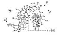
- FIG. 1is a side view of a latch assembly in an open position according to an embodiment of the invention
- FIG. 2is a side view of the latch assembly in a safety position according to an embodiment of the invention
- FIG. 3is a side view of the latch assembly in a closed position according to an embodiment of the invention.
- FIG. 4is a schematic view of an embodiment of a latch connector that may be used with the latch assembly shown in FIGS. 1-3 ;
- FIG. 5is a schematic view of another embodiment of a latch connector that may be used with the latch assembly shown in FIGS. 1-3 ;
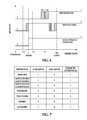
- FIG. 6is a graph showing the operational relationship among the latch assembly, a claw switch, a pawl switch, and the latch connector shown in FIG. 4 ;
- FIG. 7is a chart showing the operational relationship among the latch assembly, the claw switch, the pawl switch, and the latch connector shown in FIG. 4 ;
- FIG. 8is a graph showing the operational relationship among the latch assembly, the claw switch, the pawl switch, and the latch connector shown in FIG. 5 ;
- FIG. 9is a chart showing the operational relationship among the latch assembly, the claw switch, the pawl switch, and the latch connector shown in FIG. 5 .
- Described hereinis an exemplary latch assembly that includes an integrated pawl switch for use in detecting a true position of a vehicle door, such as a power sliding door.
- the pawl switchis connected in parallel with a claw switch using existing electrical wiring such that the switches provide an electrical status of the latch in different door positions.
- Latch assembly 10is illustrated in an open position ( FIG. 1 ), an intermediate safety position ( FIG. 2 ), and a closed position ( FIG. 3 ).
- Latch assembly 10may be integrated into a component of a vehicle, such as the vehicle door, trunk, frame surrounding the door opening or trunk opening, or any other operable component for example.
- Latch assembly 10generally includes a claw 12 , a cooperating pawl 14 , a switch cam 16 , a pawl lifter 18 , a claw switch 20 , and a pawl switch 22 .
- Claw 12is pivotally or rotationally mounted about a pin 56 that is received within an opening 24 .
- Claw 12is capable of rotational movement between an open or unlatched position shown in FIG. 1 and a closed or latched position shown in FIG. 3 , wherein claw 12 rotates in the direction of arrows 26 .
- Latch assembly 10is attached to a vehicle structure such that claw 12 is moved between the open position ( FIG. 1 ) and the closed position ( FIG. 3 ) when a door, window, lift gate, etc. is opened and closed and claw 12 engages a striker (not shown) that is attached to the door, window, lift gate, etc.
- latch assembly 10includes safety position ( FIG. 2 ) that is an intermediate position between the open position and the closed position.
- latch assembly 10is secured to the door, window, lift gate, etc. and the striker is secured to the vehicle body at an opening into which the door, window, lift gate, etc. is received. The cooperation of a claw and striker is well known and need not be described in detail.
- Pawl 14is pivotally mounted by a stud 28 received within a stud aperture 30 formed within pawl 14 .
- Pawl 14cooperates with claw 12 in a well-known manner to retain claw 12 in the safety position ( FIG. 2 ) and the closed position ( FIG. 3 ), or release claw 12 for return to the open position ( FIG. 1 ). That is, pawl 14 pivots between a release or disengaged first position shown in FIG. 1 in the direction of arrows 32 , a closed or engaged second position shown in FIG. 2 , and a closed or engaged third position shown in FIG. 3 .
- claw 12is spring biased clockwise to the open position shown in FIG.
- a biasing member(not shown; e.g., coil or torsion spring or other equivalent member) that has one end attached to claw 12 and the other end attached to a housing or other equivalent location.
- a biasing memberbiases pawl 14 in the direction of arrow 34 A against a face of claw 12 .
- claw 12has a surface 36 that slides along a complimentary surface 38 of pawl 14 when claw 12 rotates from the open position ( FIG. 1 ) to the closed position ( FIG. 3 ). Once in the closed position ( FIG. 3 ), a claw shoulder portion 40 engages a pawl shoulder portion 42 thus engaging claw 12 and securing it into the closed position when the striker is secured in a receiving opening 44 of claw 12 .
- pawl 14is spring biased in the direction of arrow 34 A and shoulder 40 engages shoulder 42 such that claw 12 cannot rotate into the open position unless pawl 14 is moved back to the release position (e.g., moving shoulder 42 away from shoulder 40 ) allowing claw 12 to rotate in the direction of arrow 34 into the open position.
- Claw 12also includes a second shoulder portion 46 that is engaged by pawl shoulder portion 42 when claw 12 has been engaged by the striker as the door is closed to the safety position ( FIG. 2 ), at which point the door is still slightly ajar, with little or no compression of its weather seals (not shown), for example.
- claw second shoulder portion 46engages pawl shoulder portion 42 thus engaging claw 12 and securing it into the first safety position.
- pawl 14is spring biased in the direction of arrow 34 A and shoulder 46 engages shoulder 42 such that claw 12 cannot rotate into the open position unless pawl 14 is moved back to the release position (e.g., moving shoulder 42 away from shoulder 40 ) allowing claw 12 to rotate in the direction of arrow 34 into the open position.
- a controller 48in communication with a power closing mechanism 49 (shown schematically) actuates power closing mechanism 49 to transition assembly 10 to the closed position ( FIG. 3 ).
- latch assembly 10includes a pawl sensor assembly 50 and a claw sensor assembly 52 , which are in communication with controller 48 .
- Pawl sensor assembly 50includes pawl switch 22 and pawl lifter 18 , which facilitates transitioning pawl switch 22 between an “on” condition and an “off” condition for communication with controller 48 .
- Pawl lifter 18is pivotally or rotationally mounted by stud 28 received within stud aperture 30 , and pawl lifter 18 may rotate with pawl 14 during rotation of pawl lifter 18 .
- pawl lifter 18includes an engagement surface 54 configured to selectively engage pawl switch 22 . In the open position ( FIG. 1 ), engagement surface 54 is not in contact with pawl switch 22 such that pawl lifter 18 is in the switch-on position. Engagement surface 54 contacts pawl switch 22 when claw 12 is in the safety position ( FIG. 2 ) and in the closed position ( FIG. 3 ) such that pawl lifter 18 is in a switch-off position.
- Claw sensor assembly 52includes claw switch 20 and switch cam 16 , which facilitates transitioning claw switch 20 between an “on” condition and an “off” condition for communication with controller 48 .
- Switch cam 16is pivotally or rotationally mounted by a pin 56 received within claw opening 24 , and switch cam 16 may rotate with claw 12 during rotation of switch cam 16 .
- switch cam 16includes a contact surface 58 configured to selectively engage claw switch 20 . In the open position ( FIG. 1 ) and in the safety position ( FIG. 2 ), contact surface 58 is in contact with claw switch 20 such that switch cam 16 is in a switch-on position. Contact surface 58 does not contact claw switch 20 when claw 12 is in the closed position ( FIG. 3 ) such that switch cam 16 is in a switch-off position.
- claw switch 20 and pawl switch 22are each microswitches that provide a signal to controller 48 , as described herein in more detail.
- switches 20 and 22may be any suitable switch or sensor that enables assembly 10 to function as described herein.
- Claw switch 20is positioned to engage switch cam 16 such that rotation of claw 12 from the closed position to the safety position and/or open position causes claw switch 20 to transition from an “off” position to an “on” position.
- claw switch 20have may any suitable position or condition that enables system 10 to function as described herein.
- claw switch 20sends a signal (or indicates a lack of a signal) to controller 48 to indicate that latch assembly 10 is in the closed position ( FIG. 3 ).
- claw switch 20sends a signal (or indicates a lack of a signal) to controller 48 to indicate that latch assembly 10 is in the safety position ( FIG. 2 ) or the open position ( FIG. 1 ).
- pawl switch 22is positioned to engage pawl lifter 18 such that rotation of pawl 14 from the first position ( FIG. 1 ) to the second position ( FIG. 2 ) or the third position ( FIG. 3 ) causes pawl switch 22 to transition from an “on” position to an “off” position.
- pawl switch 22have may any suitable position or condition that enables system 10 to function as described herein.
- pawl switch 22sends a signal (or indicates a lack of a signal) to controller 48 to indicate that latch assembly 10 is in the first safety position ( FIG. 2 ) or the closed position ( FIG. 3 ).
- pawl switch 22sends a signal (or indicates a lack of a signal) to controller 48 to indicate that latch assembly 10 is in the open position ( FIG. 1 ).
- latch assembly 10includes an electrical circuit or latch connector 60 where pawl switch 22 is connected in parallel with claw switch 20 such that only two wires A, B are required to communicatively couple switches 20 and 22 to controller 48 .
- FIG. 5illustrates an alternative embodiment of latch connector 60 that includes a resistor 62 connected in serial with claw switch 20 , which facilitates controller 48 detecting when latch assembly 10 is in the safety position ( FIG. 2 ). As such, a different voltage is on the wire due to resistor 62 , which provides at least three different types of signals to controller 48 . For example, with reference to FIGS. 6 and 8 , a 0 (zero) signal may indicate no resistance, a 0.5 signal may indicate an intermediate resistance, and a 1 signal may indicate a high resistance. Controller 48 may then translate these signals to determine the position or condition of latch assembly 10 .
- FIGS. 6-9illustrate correlations among the position of a vehicle door corresponding to the position of latch assembly 10 , the output signal from claw switch 20 , the output signal from pawl switch 22 , and a signal result on latch connector 60 wire B.
- FIGS. 6 and 7illustrate correlations when latch connector 60 does not include resistor 62
- FIGS. 8 and 9illustrate correlations when latch connector 60 includes resistor 62 .
- claw 12begins in an unlatched position ( FIG. 1 ) corresponding to a component such as a vehicle door being in an open position.
- Switch cam 16is oriented in the switch-on position such that switch cam contact surface 58 contacts claw switch 20 into the “on” state where claw switch 20 sends a signal to controller 48 indicating the vehicle door is in the open/safety position.
- Pawl 14is in the first position and pawl lifter 18 is oriented in the switch-on position such that pawl lifter engagement surface 54 does not contact pawl switch 22 .
- pawl switch 22is in the “on” state where pawl switch 22 sends a signal to controller 48 that indicates the vehicle door is in the open position. Accordingly, switches 20 , 22 indicate to controller 48 that the vehicle door is open.
- claw 12rotates counter-clockwise and pawl 14 rotates from the first position ( FIG. 1 ) where it is disengaged from claw 12 to the second position ( FIG. 2 ) where pawl shoulder 42 engages claw shoulder 40 to prevent the vehicle door from accidentally moving to the open position.
- contact surface 58remains in contact with claw switch 20 , and pawl 14 has rotated clockwise causing engagement surface 54 to contact pawl switch 22 , thereby transitioning switch 22 to the “off” condition.
- claw switch 20sends a signal to controller 48 indicating that the vehicle door is in the open or safety position
- pawl switch 22sends a signal to controller 48 that indicates the vehicle door is in the safety or closed position.
- Controller 48may subsequently actuate the motor of power closing mechanism 49 to commence a power close operation where claw 12 is rotated counter-clockwise into the latched position ( FIG. 3 ) to safely secure the door in a closed position.
- claw 12rotates to the latched position and pawl 14 rotates to the third position ( FIG. 3 ). Accordingly, in the door closed position, engagement surface 54 remains in contact with pawl switch 22 , and switch cam 16 has been rotated out of engagement with claw switch 20 , thereby transitioning switch 20 to the “off” condition. As such, claw switch 20 sends a signal to controller 48 that indicates the vehicle door is in the closed position. Controller 48 may then cease the power close operation and power-off the power close mechanism motor.
- latch assembly 10may then be repeated as the door again moves from the open position ( FIG. 1 ), to the safety position ( FIG. 2 ), and to the closed position ( FIG. 3 ).
- the latch assemblyfor detecting a position of a vehicle door.
- the latch assemblyincludes a claw switch and a pawl switch connected in parallel.
- the claw switch and pawl switchmay be coupled in parallel using only two wires.
- the switchesare communicatively coupled to a controller (e.g., vehicle electronics) and are selectively engaged by portions of the latch assembly to indicate various positions of the vehicle door depending on whether the switches are in an “on/off” condition.
- a resistormay be coupled in serial with the claw switch. Accordingly, the dual switches facilitate improved indication of door position, and thus, improved door operation, improved door closure safety, and increased vehicle occupant safety.
Landscapes
- Lock And Its Accessories (AREA)
Abstract
Description
- This application claims foreign priority to French Patent Application No. 13/62345 filed on Dec. 10, 2013, under 35 U.S.C. §119, the contents of which are incorporated herein by reference thereto.
- Exemplary embodiments of the present invention relate generally to latches and, more particularly, to latches for vehicles.
- Some known vehicles typically include displaceable panels such as doors, windows, hood, trunk lid, hatch and the like which are affixed for hinged or sliding engagement with a vehicle body. Cooperating systems of latches and strikers are typically provided to ensure that such panels remain secured in their fully closed position when the panel is closed.
- A latch typically includes a fork bolt or claw that is pivoted between an unlatched position and a primary latched position when the door is closed to latch the door in the closed position. The fork bolt is typically held in the primary latched position by a detent lever or pawl that pivots between an engaged position and a disengaged position. The detent lever holds the fork bolt in the primary latched position when in the engaged position and releases the fork bolt when in the disengaged position so that the door can be opened.
- The fork bolt is pivoted to the primary latched position by a striker attached to, for example, an associated doorjamb when the door is closed. Once in the primary latched position, the detent lever engages the fork bolt to ensure the assembly remains latched.
- In some known vehicles, doors may be automatically power closed by a motor when the door is in a certain position, for example, a first safety position. Due to a high clearance during transition to the latch closing position, a switch associated with the detent lever may fail to indicate when the door is closed. This may lead to the motor operating in a stall position for an undesirable amount of time. Accordingly, it is desirable to provide an improved latch assembly.
- In one non-limiting embodiment, a latch assembly is provided. The latch assembly includes a claw movable between a latched position and an unlatched position, and a pawl movable between a first position and a second position, the pawl engaging and holding the claw in the latched position when the pawl is in the first position, the pawl disengaging the claw for movement to the unlatched position when the pawl is in the second position. The system also includes a pawl lifter operatively associated with the pawl, the pawl lifter movable between a switch-off position when the pawl is in the first position and a switch-on position when the pawl is in the second position, and a pawl switch configured to generate a pawl switch signal, the pawl lifter engaging the pawl switch to an “on” condition when the pawl lifter is in the switch-on position, and the pawl lifter disengaging the pawl switch to an “off” condition when the pawl lifter is in the switch-off position.
- In another non-limiting embodiment, a vehicle is provided. The vehicle includes a controller, a door, and a door latch assembly. The door latch assembly includes a claw movable between a latched position and an unlatched position, and a pawl movable between a first position and a second position, the pawl engaging and holding the claw in the latched position when the pawl is in the first position, the pawl disengaging the claw for movement to the unlatched position when the pawl is in the second position. The assembly further includes a pawl lifter operatively associated with the pawl, the pawl lifter movable between a switch-off position when the pawl is in the first position and a switch-on position when the pawl is in the second position, and a pawl switch communicatively coupled to the controller, the pawl switch configured to generate a pawl switch signal, the pawl lifter engaging the pawl switch to an “on” condition when the pawl lifter is in the switch-on position, and the pawl lifter disengaging the pawl switch to an “off” condition when the pawl lifter is in the switch-off position.
- In yet another non-limiting embodiment, a method of detecting the position of a door of a vehicle is provided, the vehicle having a latch assembly including a claw, a pawl, a switch cam operatively associated with the claw, a pawl lifter operatively associated with the pawl, a pawl switch, and a controller. The method includes providing the claw movable between a latched position and an unlatched position, providing the pawl movable between a first position and a second position, the pawl engaging and holding the claw in the latched position when the pawl is in the first position, the pawl disengaging the claw for movement to the unlatched position when the pawl is in the second position, and operatively associating the pawl lifter with the pawl such that the pawl lifter is movable between a switch-off position when the pawl is in the first position and a switch-on position when the pawl is in the second position. The method further includes providing a pawl switch communicatively coupled to the controller and configured to generate a pawl switch signal, and orienting the pawl switch such that the pawl lifter engages the pawl switch to an “on” condition when the pawl lifter is in the switch-on position, and the pawl lifter disengages the pawl switch to an “off” condition when the pawl lifter is in the switch-off position. The method further includes indicating to the controller, with the pawl switch signal, a door open position condition of the latch assembly when the pawl switch is in the “on” condition, and indicating to the controller, with the pawl switch signal, a door safety position or closed condition of the latch assembly when the pawl switch is in the “off” condition.
- The above-described and other features and advantages of the present invention will be appreciated and understood by those skilled in the art from the following detailed description, drawings, and appended claims.
- Embodiments of the present invention will now be described, by way of example only, with reference to the accompanying drawings in which:
FIG. 1 is a side view of a latch assembly in an open position according to an embodiment of the invention;FIG. 2 is a side view of the latch assembly in a safety position according to an embodiment of the invention;FIG. 3 is a side view of the latch assembly in a closed position according to an embodiment of the invention;FIG. 4 is a schematic view of an embodiment of a latch connector that may be used with the latch assembly shown inFIGS. 1-3 ;FIG. 5 is a schematic view of another embodiment of a latch connector that may be used with the latch assembly shown inFIGS. 1-3 ;FIG. 6 is a graph showing the operational relationship among the latch assembly, a claw switch, a pawl switch, and the latch connector shown inFIG. 4 ;FIG. 7 is a chart showing the operational relationship among the latch assembly, the claw switch, the pawl switch, and the latch connector shown inFIG. 4 ;FIG. 8 is a graph showing the operational relationship among the latch assembly, the claw switch, the pawl switch, and the latch connector shown inFIG. 5 ; andFIG. 9 is a chart showing the operational relationship among the latch assembly, the claw switch, the pawl switch, and the latch connector shown inFIG. 5 .- Described herein is an exemplary latch assembly that includes an integrated pawl switch for use in detecting a true position of a vehicle door, such as a power sliding door. The pawl switch is connected in parallel with a claw switch using existing electrical wiring such that the switches provide an electrical status of the latch in different door positions.
- Referring now to the FIGS., an
exemplary latch assembly 10 is illustrated in an open position (FIG. 1 ), an intermediate safety position (FIG. 2 ), and a closed position (FIG. 3 ).Latch assembly 10 may be integrated into a component of a vehicle, such as the vehicle door, trunk, frame surrounding the door opening or trunk opening, or any other operable component for example.Latch assembly 10 generally includes aclaw 12, a cooperatingpawl 14, aswitch cam 16, apawl lifter 18, aclaw switch 20, and apawl switch 22. Claw 12 is pivotally or rotationally mounted about apin 56 that is received within an opening24.Claw 12 is capable of rotational movement between an open or unlatched position shown inFIG. 1 and a closed or latched position shown inFIG. 3 , whereinclaw 12 rotates in the direction ofarrows 26.Latch assembly 10 is attached to a vehicle structure such thatclaw 12 is moved between the open position (FIG. 1 ) and the closed position (FIG. 3 ) when a door, window, lift gate, etc. is opened and closed andclaw 12 engages a striker (not shown) that is attached to the door, window, lift gate, etc. In the exemplary embodiment,latch assembly 10 includes safety position (FIG. 2 ) that is an intermediate position between the open position and the closed position. In other embodiments,latch assembly 10 is secured to the door, window, lift gate, etc. and the striker is secured to the vehicle body at an opening into which the door, window, lift gate, etc. is received. The cooperation of a claw and striker is well known and need not be described in detail.- Pawl14 is pivotally mounted by a
stud 28 received within astud aperture 30 formed withinpawl 14. Pawl14 cooperates withclaw 12 in a well-known manner to retainclaw 12 in the safety position (FIG. 2 ) and the closed position (FIG. 3 ), or releaseclaw 12 for return to the open position (FIG. 1 ). That is,pawl 14 pivots between a release or disengaged first position shown inFIG. 1 in the direction ofarrows 32, a closed or engaged second position shown inFIG. 2 , and a closed or engaged third position shown inFIG. 3 . In the exemplary embodiment,claw 12 is spring biased clockwise to the open position shown inFIG. 1 or in the direction ofarrow 34 by a biasing member (not shown; e.g., coil or torsion spring or other equivalent member) that has one end attached toclaw 12 and the other end attached to a housing or other equivalent location. Similarly, a biasing member (not shown)biases pawl 14 in the direction ofarrow 34A against a face ofclaw 12. - In the exemplary embodiment,
claw 12 has asurface 36 that slides along acomplimentary surface 38 ofpawl 14 whenclaw 12 rotates from the open position (FIG. 1 ) to the closed position (FIG. 3 ). Once in the closed position (FIG. 3 ), aclaw shoulder portion 40 engages apawl shoulder portion 42 thus engagingclaw 12 and securing it into the closed position when the striker is secured in a receiving opening44 ofclaw 12. Once thelatch assembly 10 is in the closed position,pawl 14 is spring biased in the direction ofarrow 34A andshoulder 40 engagesshoulder 42 such thatclaw 12 cannot rotate into the open position unlesspawl 14 is moved back to the release position (e.g., movingshoulder 42 away from shoulder40) allowingclaw 12 to rotate in the direction ofarrow 34 into the open position. Claw 12 also includes asecond shoulder portion 46 that is engaged bypawl shoulder portion 42 whenclaw 12 has been engaged by the striker as the door is closed to the safety position (FIG. 2 ), at which point the door is still slightly ajar, with little or no compression of its weather seals (not shown), for example. Once in the safety position (FIG. 2 ), clawsecond shoulder portion 46 engagespawl shoulder portion 42 thus engagingclaw 12 and securing it into the first safety position. Oncelatch assembly 10 is in the closed position,pawl 14 is spring biased in the direction ofarrow 34A andshoulder 46 engagesshoulder 42 such thatclaw 12 cannot rotate into the open position unlesspawl 14 is moved back to the release position (e.g., movingshoulder 42 away from shoulder40) allowingclaw 12 to rotate in the direction ofarrow 34 into the open position. Further, in the exemplary embodiment, oncelatch assembly 10 is in the first safety position, acontroller 48 in communication with a power closing mechanism49 (shown schematically) actuatespower closing mechanism 49 totransition assembly 10 to the closed position (FIG. 3 ).- In the exemplary embodiment,
latch assembly 10 includes apawl sensor assembly 50 and aclaw sensor assembly 52, which are in communication withcontroller 48. Pawl sensor assembly 50 includespawl switch 22 andpawl lifter 18, which facilitates transitioningpawl switch 22 between an “on” condition and an “off” condition for communication withcontroller 48.Pawl lifter 18 is pivotally or rotationally mounted bystud 28 received withinstud aperture 30, andpawl lifter 18 may rotate withpawl 14 during rotation ofpawl lifter 18. In the exemplary embodiment,pawl lifter 18 includes anengagement surface 54 configured to selectively engagepawl switch 22. In the open position (FIG. 1 ),engagement surface 54 is not in contact withpawl switch 22 such thatpawl lifter 18 is in the switch-on position.Engagement surface 54contacts pawl switch 22 whenclaw 12 is in the safety position (FIG. 2 ) and in the closed position (FIG. 3 ) such thatpawl lifter 18 is in a switch-off position.Claw sensor assembly 52 includesclaw switch 20 andswitch cam 16, which facilitates transitioningclaw switch 20 between an “on” condition and an “off” condition for communication withcontroller 48.Switch cam 16 is pivotally or rotationally mounted by apin 56 received within claw opening24, and switchcam 16 may rotate withclaw 12 during rotation ofswitch cam 16. In the exemplary embodiment,switch cam 16 includes acontact surface 58 configured to selectively engageclaw switch 20. In the open position (FIG. 1 ) and in the safety position (FIG. 2 ),contact surface 58 is in contact withclaw switch 20 such thatswitch cam 16 is in a switch-on position.Contact surface 58 does not contactclaw switch 20 whenclaw 12 is in the closed position (FIG. 3 ) such thatswitch cam 16 is in a switch-off position.- In the exemplary embodiment, claw
switch 20 andpawl switch 22 are each microswitches that provide a signal tocontroller 48, as described herein in more detail. However, switches20 and22 may be any suitable switch or sensor that enables assembly10 to function as described herein.Claw switch 20 is positioned to engageswitch cam 16 such that rotation ofclaw 12 from the closed position to the safety position and/or open position causesclaw switch 20 to transition from an “off” position to an “on” position. Although described as “off” and “on” positions, clawswitch 20 have may any suitable position or condition that enablessystem 10 to function as described herein. In the “off” position, clawswitch 20 sends a signal (or indicates a lack of a signal) tocontroller 48 to indicate thatlatch assembly 10 is in the closed position (FIG. 3 ). In the “on” position, clawswitch 20 sends a signal (or indicates a lack of a signal) tocontroller 48 to indicate thatlatch assembly 10 is in the safety position (FIG. 2 ) or the open position (FIG. 1 ). - In the exemplary embodiment,
pawl switch 22 is positioned to engagepawl lifter 18 such that rotation ofpawl 14 from the first position (FIG. 1 ) to the second position (FIG. 2 ) or the third position (FIG. 3 ) causespawl switch 22 to transition from an “on” position to an “off” position. Although described as “off” and “on” positions,pawl switch 22 have may any suitable position or condition that enablessystem 10 to function as described herein. In the “off” position,pawl switch 22 sends a signal (or indicates a lack of a signal) tocontroller 48 to indicate thatlatch assembly 10 is in the first safety position (FIG. 2 ) or the closed position (FIG. 3 ). In the “on” position,pawl switch 22 sends a signal (or indicates a lack of a signal) tocontroller 48 to indicate thatlatch assembly 10 is in the open position (FIG. 1 ). - As shown in
FIG. 4 ,latch assembly 10 includes an electrical circuit or latchconnector 60 where pawl switch22 is connected in parallel withclaw switch 20 such that only two wires A, B are required to communicatively couple switches20 and22 tocontroller 48.FIG. 5 illustrates an alternative embodiment oflatch connector 60 that includes aresistor 62 connected in serial withclaw switch 20, which facilitatescontroller 48 detecting whenlatch assembly 10 is in the safety position (FIG. 2 ). As such, a different voltage is on the wire due toresistor 62, which provides at least three different types of signals tocontroller 48. For example, with reference toFIGS. 6 and 8 , a 0 (zero) signal may indicate no resistance, a 0.5 signal may indicate an intermediate resistance, and a 1 signal may indicate a high resistance.Controller 48 may then translate these signals to determine the position or condition oflatch assembly 10. - With reference to
FIGS. 6-9 , an exemplary operation oflatch assembly 10 is described herein.FIGS. 6-9 illustrate correlations among the position of a vehicle door corresponding to the position oflatch assembly 10, the output signal fromclaw switch 20, the output signal frompawl switch 22, and a signal result onlatch connector 60 wire B.FIGS. 6 and 7 illustrate correlations whenlatch connector 60 does not includeresistor 62, andFIGS. 8 and 9 illustrate correlations whenlatch connector 60 includesresistor 62. - In the exemplary operation, claw12 begins in an unlatched position (
FIG. 1 ) corresponding to a component such as a vehicle door being in an open position.Switch cam 16 is oriented in the switch-on position such that switchcam contact surface 58 contacts clawswitch 20 into the “on” state where claw switch20 sends a signal tocontroller 48 indicating the vehicle door is in the open/safety position.Pawl 14 is in the first position andpawl lifter 18 is oriented in the switch-on position such that pawllifter engagement surface 54 does not contactpawl switch 22. As such,pawl switch 22 is in the “on” state where pawl switch22 sends a signal tocontroller 48 that indicates the vehicle door is in the open position. Accordingly, switches20,22 indicate tocontroller 48 that the vehicle door is open. - As the vehicle door moves from the open position (
FIG. 1 ) to the safety position (FIG. 2 ),claw 12 rotates counter-clockwise andpawl 14 rotates from the first position (FIG. 1 ) where it is disengaged fromclaw 12 to the second position (FIG. 2 ) wherepawl shoulder 42 engagesclaw shoulder 40 to prevent the vehicle door from accidentally moving to the open position. As such,contact surface 58 remains in contact withclaw switch 20, andpawl 14 has rotated clockwise causingengagement surface 54 to contactpawl switch 22, thereby transitioningswitch 22 to the “off” condition. As such,claw switch 20 sends a signal tocontroller 48 indicating that the vehicle door is in the open or safety position, andpawl switch 22 sends a signal tocontroller 48 that indicates the vehicle door is in the safety or closed position.Controller 48 may subsequently actuate the motor ofpower closing mechanism 49 to commence a power close operation whereclaw 12 is rotated counter-clockwise into the latched position (FIG. 3 ) to safely secure the door in a closed position. - As the vehicle door moves from the safety position (
FIG. 2 ) to the closed position (FIG. 3 ),claw 12 rotates to the latched position andpawl 14 rotates to the third position (FIG. 3 ). Accordingly, in the door closed position,engagement surface 54 remains in contact withpawl switch 22, and switchcam 16 has been rotated out of engagement withclaw switch 20, thereby transitioningswitch 20 to the “off” condition. As such,claw switch 20 sends a signal tocontroller 48 that indicates the vehicle door is in the closed position.Controller 48 may then cease the power close operation and power-off the power close mechanism motor. - As the vehicle door returns to the open position (
FIG. 1 ),pawl 14 disengages claw12, and claw12 rotates clockwise from the latched position (FIG. 3 ) to the unlatched position (FIG. 1 ). As such,contact surface 58 engagesclaw switch 20 indicating to controller48 a door open or safety position, andpawl lifter 18 rotates out of engagement withpawl switch 22 indicating to controller48 a door open position. The operation oflatch assembly 10 may then be repeated as the door again moves from the open position (FIG. 1 ), to the safety position (FIG. 2 ), and to the closed position (FIG. 3 ). - Described herein is a latch assembly for detecting a position of a vehicle door. The latch assembly includes a claw switch and a pawl switch connected in parallel. Economically, the claw switch and pawl switch may be coupled in parallel using only two wires. The switches are communicatively coupled to a controller (e.g., vehicle electronics) and are selectively engaged by portions of the latch assembly to indicate various positions of the vehicle door depending on whether the switches are in an “on/off” condition. Further, a resistor may be coupled in serial with the claw switch. Accordingly, the dual switches facilitate improved indication of door position, and thus, improved door operation, improved door closure safety, and increased vehicle occupant safety.
- While the invention has been described with reference to an exemplary embodiment, it will be understood by those skilled in the art that various changes may be made and equivalents may be substituted for elements thereof without departing from the scope of the invention. In addition, many modifications may be made to adapt a particular situation or material to the teachings of the invention without departing from the essential scope thereof Therefore, it is intended that the invention not be limited to the particular embodiment disclosed as the best mode contemplated for carrying out this invention, but that the invention will include all embodiments falling within the scope of the appended claims.
Claims (19)
Applications Claiming Priority (2)
| Application Number | Priority Date | Filing Date | Title |
|---|---|---|---|
| FR1362345 | 2013-12-10 | ||
| FR1362345AFR3014472B1 (en) | 2013-12-10 | 2013-12-10 | ASSEMBLY AND DOOR LATCH SYSTEM |
Publications (1)
| Publication Number | Publication Date |
|---|---|
| US20150159407A1true US20150159407A1 (en) | 2015-06-11 |
Family
ID=50543141
Family Applications (1)
| Application Number | Title | Priority Date | Filing Date |
|---|---|---|---|
| US14/564,459AbandonedUS20150159407A1 (en) | 2013-12-10 | 2014-12-09 | Door latch assembly and system |
Country Status (2)
| Country | Link |
|---|---|
| US (1) | US20150159407A1 (en) |
| FR (1) | FR3014472B1 (en) |
Cited By (7)
| Publication number | Priority date | Publication date | Assignee | Title |
|---|---|---|---|---|
| US20150361690A1 (en)* | 2013-01-17 | 2015-12-17 | Illinois Tool Works Inc. | Appliance lock with voltage encoded wiring |
| WO2017153835A1 (en)* | 2016-03-11 | 2017-09-14 | Kiekert Ag | Latch unit for a motor vehicle |
| US20170350173A1 (en)* | 2016-06-07 | 2017-12-07 | Magna Closures Inc. | Vehicular closure latch assembly having double pawl latch mechanism |
| JP2018100492A (en)* | 2016-12-19 | 2018-06-28 | 株式会社ケーヒン | Control device for vehicular electronic door |
| US11118379B2 (en)* | 2015-06-02 | 2021-09-14 | Kiekert Ag | Method for controlling a motor vehicle door lock |
| WO2024133481A1 (en)* | 2022-12-22 | 2024-06-27 | Brose Schliesssysteme Gmbh & Co. Kommanditgesellschaft | Switch configuration for motor vehicle latch |
| CN119616315A (en)* | 2024-12-04 | 2025-03-14 | 重庆赛力斯凤凰智创科技有限公司 | Door lock motor control method and device, electronic equipment and storage medium |
Families Citing this family (1)
| Publication number | Priority date | Publication date | Assignee | Title |
|---|---|---|---|---|
| DE102021102766A1 (en)* | 2021-02-05 | 2022-08-11 | Brose Schließsysteme GmbH & Co. Kommanditgesellschaft | Motor vehicle lock arrangement for a flap of a motor vehicle |
Citations (21)
| Publication number | Priority date | Publication date | Assignee | Title |
|---|---|---|---|---|
| DE3242527A1 (en)* | 1982-11-18 | 1984-05-24 | Neiman GmbH, 5657 Haan | ELECTRIC LOCK |
| US4762348A (en)* | 1985-10-30 | 1988-08-09 | Ohi Seisakusho Co., Ltd. | Electric door lock system |
| US4896908A (en)* | 1987-12-02 | 1990-01-30 | Kiekert Gmbh & Co. Kommanditgesellschaft | Elastomer-clad motor-vehicle door latch |
| US5138795A (en)* | 1990-04-25 | 1992-08-18 | General Motors Corporation | Power sliding door closer |
| US6050117A (en)* | 1995-10-13 | 2000-04-18 | Robert Bosch Gmbh | Motor vehicle door lock or the like |
| US6113162A (en)* | 1997-10-14 | 2000-09-05 | Ohi Seisakusho Co., Ltd. | Door open/close detector |
| US20010010427A1 (en)* | 1998-06-24 | 2001-08-02 | Mannesmann Vdo Ag | Power-assisted closing device |
| US6435573B1 (en)* | 1997-06-17 | 2002-08-20 | Huf Hülsbeck & Fürst Gmbh & Co. Kg | Rotating catch lock, specially for motor vehicles |
| FR2837232A1 (en)* | 2002-03-15 | 2003-09-19 | Meritor Light Vehicle Sys Ltd | MOTOR VEHICLE LOCK |
| US6848727B1 (en)* | 1999-02-18 | 2005-02-01 | Atoma International Corp | Power door latch assembly |
| US20060076784A1 (en)* | 2004-09-02 | 2006-04-13 | Brose Schliesssysteme Gmbh & Co. Kg | Motor vehicle lock |
| DE102006048026A1 (en)* | 2005-11-08 | 2007-05-10 | BROSE SCHLIEßSYSTEME GMBH & CO. KG | Motor vehicle lock e.g. door lock, arrangement, has control unit accessing directly on sensor signals of latch sensor and/or ratchet sensor and providing input signal for other control unit that indirectly accesses sensor signals |
| DE102006042399A1 (en)* | 2005-12-21 | 2007-07-05 | BROSE SCHLIEßSYSTEME GMBH & CO. KG | Drive arrangement for motorized drive of motor-vehicle tail-gate /flap, has tail-gate /flap control with adjustment sensor giving output signal to tail-gate /flap control |
| US20100194120A1 (en)* | 2007-05-30 | 2010-08-05 | Kaiser Hans-Guenter | Closure for vehicles |
| DE202009016636U1 (en)* | 2009-12-09 | 2011-04-21 | BROSE SCHLIEßSYSTEME GMBH & CO. KG | Motor vehicle lock |
| US20120061977A1 (en)* | 2010-09-15 | 2012-03-15 | Norihide Takeda | Door closer apparatus |
| US20130249222A1 (en)* | 2012-03-26 | 2013-09-26 | Mitsui Kinzoku Act Corporation | Door closer device |
| US8684424B2 (en)* | 2007-06-01 | 2014-04-01 | Valeo Securite Habitacle | Closing assisted electric lock for opening of automobile |
| US20150233145A1 (en)* | 2012-09-13 | 2015-08-20 | Kabushiki Kaisha Honda Lock | Controller for energizing vehicle door lock indicator |
| US20150267441A1 (en)* | 2012-10-24 | 2015-09-24 | Kiekert Aktiengesellschaft | Motor vehicle lock with position detection means |
| US20170159334A1 (en)* | 2014-07-01 | 2017-06-08 | Gecom Corporation | Motor vehicle door latch device |
Family Cites Families (4)
| Publication number | Priority date | Publication date | Assignee | Title |
|---|---|---|---|---|
| EP0808977B1 (en)* | 1996-05-21 | 2000-08-16 | Robert Bosch Gmbh | Method for controlling an electrically actuated vehicle door lock |
| FR2778939B1 (en)* | 1998-05-20 | 2002-12-06 | Valeo Securite Habitacle | CLOSING STATE INDICATOR FOR A MOTOR VEHICLE DOOR LOCK AND LOCK INCORPORATING SUCH AN INDICATOR |
| EP2071106B1 (en)* | 2007-12-14 | 2015-10-28 | Volvo Car Corporation | Power closing latch device |
| JP5978484B2 (en)* | 2011-08-31 | 2016-08-24 | 三井金属アクト株式会社 | Vehicle door latch device |
- 2013
- 2013-12-10FRFR1362345Apatent/FR3014472B1/enactiveActive
- 2014
- 2014-12-09USUS14/564,459patent/US20150159407A1/ennot_activeAbandoned
Patent Citations (21)
| Publication number | Priority date | Publication date | Assignee | Title |
|---|---|---|---|---|
| DE3242527A1 (en)* | 1982-11-18 | 1984-05-24 | Neiman GmbH, 5657 Haan | ELECTRIC LOCK |
| US4762348A (en)* | 1985-10-30 | 1988-08-09 | Ohi Seisakusho Co., Ltd. | Electric door lock system |
| US4896908A (en)* | 1987-12-02 | 1990-01-30 | Kiekert Gmbh & Co. Kommanditgesellschaft | Elastomer-clad motor-vehicle door latch |
| US5138795A (en)* | 1990-04-25 | 1992-08-18 | General Motors Corporation | Power sliding door closer |
| US6050117A (en)* | 1995-10-13 | 2000-04-18 | Robert Bosch Gmbh | Motor vehicle door lock or the like |
| US6435573B1 (en)* | 1997-06-17 | 2002-08-20 | Huf Hülsbeck & Fürst Gmbh & Co. Kg | Rotating catch lock, specially for motor vehicles |
| US6113162A (en)* | 1997-10-14 | 2000-09-05 | Ohi Seisakusho Co., Ltd. | Door open/close detector |
| US20010010427A1 (en)* | 1998-06-24 | 2001-08-02 | Mannesmann Vdo Ag | Power-assisted closing device |
| US6848727B1 (en)* | 1999-02-18 | 2005-02-01 | Atoma International Corp | Power door latch assembly |
| FR2837232A1 (en)* | 2002-03-15 | 2003-09-19 | Meritor Light Vehicle Sys Ltd | MOTOR VEHICLE LOCK |
| US20060076784A1 (en)* | 2004-09-02 | 2006-04-13 | Brose Schliesssysteme Gmbh & Co. Kg | Motor vehicle lock |
| DE102006048026A1 (en)* | 2005-11-08 | 2007-05-10 | BROSE SCHLIEßSYSTEME GMBH & CO. KG | Motor vehicle lock e.g. door lock, arrangement, has control unit accessing directly on sensor signals of latch sensor and/or ratchet sensor and providing input signal for other control unit that indirectly accesses sensor signals |
| DE102006042399A1 (en)* | 2005-12-21 | 2007-07-05 | BROSE SCHLIEßSYSTEME GMBH & CO. KG | Drive arrangement for motorized drive of motor-vehicle tail-gate /flap, has tail-gate /flap control with adjustment sensor giving output signal to tail-gate /flap control |
| US20100194120A1 (en)* | 2007-05-30 | 2010-08-05 | Kaiser Hans-Guenter | Closure for vehicles |
| US8684424B2 (en)* | 2007-06-01 | 2014-04-01 | Valeo Securite Habitacle | Closing assisted electric lock for opening of automobile |
| DE202009016636U1 (en)* | 2009-12-09 | 2011-04-21 | BROSE SCHLIEßSYSTEME GMBH & CO. KG | Motor vehicle lock |
| US20120061977A1 (en)* | 2010-09-15 | 2012-03-15 | Norihide Takeda | Door closer apparatus |
| US20130249222A1 (en)* | 2012-03-26 | 2013-09-26 | Mitsui Kinzoku Act Corporation | Door closer device |
| US20150233145A1 (en)* | 2012-09-13 | 2015-08-20 | Kabushiki Kaisha Honda Lock | Controller for energizing vehicle door lock indicator |
| US20150267441A1 (en)* | 2012-10-24 | 2015-09-24 | Kiekert Aktiengesellschaft | Motor vehicle lock with position detection means |
| US20170159334A1 (en)* | 2014-07-01 | 2017-06-08 | Gecom Corporation | Motor vehicle door latch device |
Cited By (10)
| Publication number | Priority date | Publication date | Assignee | Title |
|---|---|---|---|---|
| US20150361690A1 (en)* | 2013-01-17 | 2015-12-17 | Illinois Tool Works Inc. | Appliance lock with voltage encoded wiring |
| US10597904B2 (en)* | 2013-01-17 | 2020-03-24 | Illinois Tool Works Inc. | Appliance lock with voltage encoded wiring |
| US11118379B2 (en)* | 2015-06-02 | 2021-09-14 | Kiekert Ag | Method for controlling a motor vehicle door lock |
| WO2017153835A1 (en)* | 2016-03-11 | 2017-09-14 | Kiekert Ag | Latch unit for a motor vehicle |
| CN107178262A (en)* | 2016-03-11 | 2017-09-19 | 开开特股份公司 | Latch lock unit for motor vehicle |
| US20170350173A1 (en)* | 2016-06-07 | 2017-12-07 | Magna Closures Inc. | Vehicular closure latch assembly having double pawl latch mechanism |
| US10745948B2 (en)* | 2016-06-07 | 2020-08-18 | Magna Closures Inc. | Vehicular closure latch assembly having double pawl latch mechanism |
| JP2018100492A (en)* | 2016-12-19 | 2018-06-28 | 株式会社ケーヒン | Control device for vehicular electronic door |
| WO2024133481A1 (en)* | 2022-12-22 | 2024-06-27 | Brose Schliesssysteme Gmbh & Co. Kommanditgesellschaft | Switch configuration for motor vehicle latch |
| CN119616315A (en)* | 2024-12-04 | 2025-03-14 | 重庆赛力斯凤凰智创科技有限公司 | Door lock motor control method and device, electronic equipment and storage medium |
Also Published As
| Publication number | Publication date |
|---|---|
| FR3014472B1 (en) | 2017-10-06 |
| FR3014472A1 (en) | 2015-06-12 |
Similar Documents
| Publication | Publication Date | Title |
|---|---|---|
| US20150159407A1 (en) | Door latch assembly and system | |
| US8967679B2 (en) | Vehicle door latch | |
| US8894106B2 (en) | Vehicle latch | |
| US10895095B2 (en) | Power closure latch assembly with cinch mechanism having ratchet retention function | |
| CN109267862B (en) | Vehicle closure latch assembly with roller latch mechanism and tie-down mechanism | |
| US11512504B2 (en) | Latch assembly with power release and dual stage cinch function | |
| US12018518B2 (en) | Vehicle latch | |
| US8882163B2 (en) | Double latch assembly for a motor vehicle | |
| US7762594B2 (en) | Uni-directional cinching latch assembly and method of operating a cinching latch assembly | |
| US20070046035A1 (en) | Vehicle door latch | |
| US20050200137A1 (en) | Latch apparatus and method | |
| US9714532B2 (en) | Latch assembly with pawl switch override device | |
| CN101457609A (en) | Power closing latch device | |
| JP2017166236A (en) | Vehicle door opening and closing device | |
| US9650816B2 (en) | Vehicle sliding door locking system and latch assembly | |
| US9739077B2 (en) | Linear rotating link switch actuation | |
| US20120007372A1 (en) | Vehicle latch with over travel stop feature | |
| CN114466964B (en) | Closure Latch Assembly | |
| JP2022041641A (en) | Vehicle door latch device | |
| EP3081730B1 (en) | Vehicle door system comprising door latch device | |
| US20110304162A1 (en) | Vehicle latch with pendulum stop on release lever | |
| CN107869283B (en) | Lifting door lock latch | |
| US20110101707A1 (en) | Vehicle latch and method of operating | |
| US10428561B2 (en) | Verification system for a vehicle latch and method | |
| CN111279042A (en) | Lock operating device with emergency unlocking function |
Legal Events
| Date | Code | Title | Description |
|---|---|---|---|
| AS | Assignment | Owner name:INTEVA PRODUCTS, LLC, MICHIGAN Free format text:ASSIGNMENT OF ASSIGNORS INTEREST;ASSIGNORS:DIDIER, JEAN BERNARD;WURTZ, DOMINIQUE;REEL/FRAME:039551/0258 Effective date:20150119 | |
| AS | Assignment | Owner name:DEUTSCHE BANK AG NEW YORK BRANCH, AS COLLATERAL AGENT, NEW YORK Free format text:SECURITY AGREEMENT;ASSIGNOR:INTEVA PRODUCTS, LLC;REEL/FRAME:039973/0305 Effective date:20160908 Owner name:DEUTSCHE BANK AG NEW YORK BRANCH, AS COLLATERAL AG Free format text:SECURITY AGREEMENT;ASSIGNOR:INTEVA PRODUCTS, LLC;REEL/FRAME:039973/0305 Effective date:20160908 | |
| AS | Assignment | Owner name:WELLS FARGO BANK, NATIONAL ASSOCIATION, NEW YORK Free format text:SECURITY AGREEMENT;ASSIGNOR:INTEVA PRODUCTS, LLC;REEL/FRAME:042857/0001 Effective date:20160908 | |
| AS | Assignment | Owner name:INTEVA PRODUCTS, LLC, MICHIGAN Free format text:RELEASE BY SECURED PARTY;ASSIGNOR:DEUTSCHE BANK AG NEW YORK BRANCH;REEL/FRAME:043038/0246 Effective date:20170627 | |
| STPP | Information on status: patent application and granting procedure in general | Free format text:DOCKETED NEW CASE - READY FOR EXAMINATION | |
| STPP | Information on status: patent application and granting procedure in general | Free format text:NON FINAL ACTION MAILED | |
| STPP | Information on status: patent application and granting procedure in general | Free format text:RESPONSE TO NON-FINAL OFFICE ACTION ENTERED AND FORWARDED TO EXAMINER | |
| STPP | Information on status: patent application and granting procedure in general | Free format text:FINAL REJECTION MAILED | |
| STPP | Information on status: patent application and granting procedure in general | Free format text:RESPONSE AFTER FINAL ACTION FORWARDED TO EXAMINER | |
| STPP | Information on status: patent application and granting procedure in general | Free format text:ADVISORY ACTION MAILED | |
| STPP | Information on status: patent application and granting procedure in general | Free format text:DOCKETED NEW CASE - READY FOR EXAMINATION | |
| STPP | Information on status: patent application and granting procedure in general | Free format text:NON FINAL ACTION MAILED | |
| STPP | Information on status: patent application and granting procedure in general | Free format text:RESPONSE TO NON-FINAL OFFICE ACTION ENTERED AND FORWARDED TO EXAMINER | |
| STPP | Information on status: patent application and granting procedure in general | Free format text:RESPONSE AFTER FINAL ACTION FORWARDED TO EXAMINER | |
| STPP | Information on status: patent application and granting procedure in general | Free format text:ADVISORY ACTION MAILED | |
| STCV | Information on status: appeal procedure | Free format text:NOTICE OF APPEAL FILED | |
| STCB | Information on status: application discontinuation | Free format text:ABANDONED -- FAILURE TO RESPOND TO AN OFFICE ACTION |