US20150148808A1 - Patient-specific acetabular alignment guide and method - Google Patents
Patient-specific acetabular alignment guide and methodDownload PDFInfo
- Publication number
- US20150148808A1 US20150148808A1US14/089,932US201314089932AUS2015148808A1US 20150148808 A1US20150148808 A1US 20150148808A1US 201314089932 AUS201314089932 AUS 201314089932AUS 2015148808 A1US2015148808 A1US 2015148808A1
- Authority
- US
- United States
- Prior art keywords
- component
- anatomical reference
- protrusions
- reference component
- guide
- Prior art date
- Legal status (The legal status is an assumption and is not a legal conclusion. Google has not performed a legal analysis and makes no representation as to the accuracy of the status listed.)
- Granted
Links
Images


Classifications
- A—HUMAN NECESSITIES
- A61—MEDICAL OR VETERINARY SCIENCE; HYGIENE
- A61F—FILTERS IMPLANTABLE INTO BLOOD VESSELS; PROSTHESES; DEVICES PROVIDING PATENCY TO, OR PREVENTING COLLAPSING OF, TUBULAR STRUCTURES OF THE BODY, e.g. STENTS; ORTHOPAEDIC, NURSING OR CONTRACEPTIVE DEVICES; FOMENTATION; TREATMENT OR PROTECTION OF EYES OR EARS; BANDAGES, DRESSINGS OR ABSORBENT PADS; FIRST-AID KITS
- A61F2/00—Filters implantable into blood vessels; Prostheses, i.e. artificial substitutes or replacements for parts of the body; Appliances for connecting them with the body; Devices providing patency to, or preventing collapsing of, tubular structures of the body, e.g. stents
- A61F2/02—Prostheses implantable into the body
- A61F2/30—Joints
- A61F2/46—Special tools for implanting artificial joints
- A61F2/4603—Special tools for implanting artificial joints for insertion or extraction of endoprosthetic joints or of accessories thereof
- A61F2/4609—Special tools for implanting artificial joints for insertion or extraction of endoprosthetic joints or of accessories thereof of acetabular cups
- A—HUMAN NECESSITIES
- A61—MEDICAL OR VETERINARY SCIENCE; HYGIENE
- A61B—DIAGNOSIS; SURGERY; IDENTIFICATION
- A61B17/00—Surgical instruments, devices or methods
- A61B17/16—Instruments for performing osteoclasis; Drills or chisels for bones; Trepans
- A61B17/17—Guides or aligning means for drills, mills, pins or wires
- A61B17/1739—Guides or aligning means for drills, mills, pins or wires specially adapted for particular parts of the body
- A61B17/1742—Guides or aligning means for drills, mills, pins or wires specially adapted for particular parts of the body for the hip
- A61B17/1746—Guides or aligning means for drills, mills, pins or wires specially adapted for particular parts of the body for the hip for the acetabulum
- A—HUMAN NECESSITIES
- A61—MEDICAL OR VETERINARY SCIENCE; HYGIENE
- A61B—DIAGNOSIS; SURGERY; IDENTIFICATION
- A61B17/00—Surgical instruments, devices or methods
- A61B17/56—Surgical instruments or methods for treatment of bones or joints; Devices specially adapted therefor
- A61B2017/568—Surgical instruments or methods for treatment of bones or joints; Devices specially adapted therefor produced with shape and dimensions specific for an individual patient
- A—HUMAN NECESSITIES
- A61—MEDICAL OR VETERINARY SCIENCE; HYGIENE
- A61F—FILTERS IMPLANTABLE INTO BLOOD VESSELS; PROSTHESES; DEVICES PROVIDING PATENCY TO, OR PREVENTING COLLAPSING OF, TUBULAR STRUCTURES OF THE BODY, e.g. STENTS; ORTHOPAEDIC, NURSING OR CONTRACEPTIVE DEVICES; FOMENTATION; TREATMENT OR PROTECTION OF EYES OR EARS; BANDAGES, DRESSINGS OR ABSORBENT PADS; FIRST-AID KITS
- A61F2/00—Filters implantable into blood vessels; Prostheses, i.e. artificial substitutes or replacements for parts of the body; Appliances for connecting them with the body; Devices providing patency to, or preventing collapsing of, tubular structures of the body, e.g. stents
- A61F2/02—Prostheses implantable into the body
- A61F2/30—Joints
- A61F2/3094—Designing or manufacturing processes
- A—HUMAN NECESSITIES
- A61—MEDICAL OR VETERINARY SCIENCE; HYGIENE
- A61F—FILTERS IMPLANTABLE INTO BLOOD VESSELS; PROSTHESES; DEVICES PROVIDING PATENCY TO, OR PREVENTING COLLAPSING OF, TUBULAR STRUCTURES OF THE BODY, e.g. STENTS; ORTHOPAEDIC, NURSING OR CONTRACEPTIVE DEVICES; FOMENTATION; TREATMENT OR PROTECTION OF EYES OR EARS; BANDAGES, DRESSINGS OR ABSORBENT PADS; FIRST-AID KITS
- A61F2/00—Filters implantable into blood vessels; Prostheses, i.e. artificial substitutes or replacements for parts of the body; Appliances for connecting them with the body; Devices providing patency to, or preventing collapsing of, tubular structures of the body, e.g. stents
- A61F2/02—Prostheses implantable into the body
- A61F2/30—Joints
- A61F2/46—Special tools for implanting artificial joints
- A61F2002/4687—Mechanical guides for implantation instruments
Definitions
- the present inventionrelates to a patient-specific alignment guide for surgical implants and instruments and more particularly to a patient-specific alignment guide that includes an anatomical reference component and an implant or instrument positioning component.
- the present inventionrelates to a patient-specific alignment guide that includes an anatomical reference component and an instrument positioning component.
- the inventionfeatures a patient specific implant alignment method including the following steps. First, obtaining one or more images of an anatomic location where an implant is to be implanted. Next, fabricating an anatomical reference component based on the one or more images.
- the anatomical reference componentcomprises at least one matching feature shaped and dimensioned to match and complement a specific feature of the anatomic location, and the anatomical reference component further comprises one or more protrusions.
- providing a guide componentcomprising one or more attachment protrusions.
- the one or more attachment protrusionsare shaped and dimensioned to match and interface with the one or more protrusions of the anatomical reference component.
- attaching the guide component to the anatomical reference componentby matching and attaching the one or more attachment protrusions of the guide component to the one or more protrusions of the anatomical reference component, and thereby aligning and orienting the guide component relative to the anatomical reference component.
- verifying the positioning and alignment of the guide component relative to the anatomical reference component and the anatomic locationattaching the guide component to the anatomic location and then using the guide component to align and insert the implant in the anatomic location.
- the anatomic locationincludes a cavity with a curved concave inner surface and the anatomical reference component comprises a curved concave cavity complementing and matching the curved concave inner surface of the anatomic location.
- Each of the one or more protrusions of the anatomical referencecomprises a threaded opening matching a corresponding threaded opening in the corresponding matching attachment protrusion of the guide component.
- the one or more attachment protrusions of the guide componentare attached to the one or more protrusions of the anatomical reference component with one of screws, clamps, pins or wires.
- the guide componentis attached to the anatomic location with one of screws, clamps, pins or wires.
- the anatomic locationis the acetabulum and the anatomical reference component includes a curved concave cavity area, a convex curved outer surface, a through opening and first and second protrusions extending from a bottom surface of the anatomical reference component and the a curved concave cavity area complements and matches the acetabulum anatomy.
- the guide componentincludes first and second slots on a top surface and the first and second protrusions of the anatomical reference component are shaped and dimensioned to slide within the first and second slots of the guide component.
- the guide componentfurther comprises an upward extending cylindrical extension and wherein the cylindrical extension comprises a through-bore.
- the methodfurther includes providing a positioning device and the positioning device comprises a rod dimensioned to be received within the through-bore of the cylindrical extension of the guide component, and the rod is a reference axis for the positioning device.
- the positioning devicemay be an implant positioning device or a surgical instrument positioning device.
- the methodfurther includes providing a reference axis for positioning an implant or a device and the reference axis may be a pin, a reference frame or an electronic alignment device.
- the electronic alignment devicemay be an RF device, a laser beam or an optical beam.
- the one or more imagesmay be computer tomography (CT) images, magnetic resonance imaging (MRI) images, ultrasound images, microwave images, Infrared images or radiographic images.
- CTcomputer tomography
- MRImagnetic resonance imaging
- ultrasound imagesmicrowave images
- the anatomical reference componentis fabricated via additive layer machining
- the methodmay further include removing the anatomical reference component prior to inserting the implant in the anatomic location.
- the inventionfeatures a patient specific implant alignment guide assembly including an anatomical reference component and a guide component.
- the anatomical reference componentcomprises at least one matching feature shaped and dimensioned to match and complement a specific feature of an anatomic location, and the anatomical reference component further comprises one or more protrusions, and the anatomical reference component is fabricated based on one or more images of the anatomic location where the implant is to be implanted.
- the guide componentincludes one or more attachment protrusions and the one or more attachment protrusions are shaped and dimensioned to match and interface with the one or more protrusions of the anatomical reference component.
- the guide componentis attached to the anatomical reference component by matching and attaching the one or more attachment protrusions of the guide component to the one or more protrusions of the anatomical reference component, and thereby the guide component is aligned and oriented relative to the anatomical reference component.
- the patient-specific alignment guide of this inventionis configured to match the specific anatomy of the surgery site. It provides reliable alignment of implants and instruments used in the surgery site.
- FIG. 1Ais a schematic perspective view of a patient-specific acetabular alignment guide system of this invention
- FIG. 1Bis an enlarged view of the patient-specific acetabular alignment guide system of FIG. 1A ;
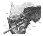
- FIG. 2Adepicts the first step in the method for applying the patient-specific acetabular alignment guide of this invention
- FIG. 2Bdepicts the second step in the method for applying the patient-specific acetabular alignment guide of this invention
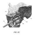
- FIG. 2Cdepicts the third step in the method for applying the patient-specific acetabular alignment guide of this invention.
- FIG. 3Adepicts the first step in the method for applying another embodiment of a patient-specific acetabular alignment guide of this invention
- FIG. 3Bdepicts the second step in the method for applying the embodiment of the patient-specific acetabular alignment guide of FIG. 3A ;
- FIG. 3Cdepicts the third step in the method for applying the embodiment of the patient-specific acetabular alignment guide of FIG. 3A ;
- FIG. 4Adepicts a top view of the anatomic reference component of the patient-specific acetabular alignment guide of FIG. 3A ;
- FIG. 4Bdepicts a bottom view of the anatomic reference component of the patient-specific acetabular alignment guide of FIG. 3A ;
- FIG. 5depicts a top perspective view of the instrument guide component of the patient-specific acetabular alignment guide of FIG. 3A ;
- FIG. 6depicts a bottom perspective view of the patient-specific acetabular alignment guide of FIG. 3A .
- the present inventionrelates to a patient-specific alignment guide that includes an anatomical reference component and an implant/instrument positioning component.
- patient-specific acetabular alignment guide systems 100 a, 100 bare attached to the left acetabulum 90 a and right acetabulum 90 b, of pelvis 80 respectively.
- Each patient-specific alignment guide systemincludes a patient-specific anatomical reference component 110 and an instrument guide component 120 .
- the anatomical reference component 110is fabricated based on computed tomography (CT), magnetic resonance imaging (MRI), ultrasound imaging, microwave imaging, Infrared imaging or other radiographic studies of the patient's anatomy and is designed to match the patient's specific anatomic features.
- the fabricated patient-specific anatomical reference component 110is attached to the specific anatomic feature, i.e., the acetabulum 90 b and then the instrument guide component 120 is attached to the anatomical reference component 110 , as shown in FIG. 2A .
- the anatomical reference component 110may be removed (as shown in FIG. 2B ) and the appropriate instrument, device or implant is inserted and attached to the guide component 120 , as shown in FIG. 2C .
- the anatomical reference component 110is designed to match the acetabulum anatomy and it includes a convex curved outer surface 114 , a concave cavity area 112 and protrusions 111 with threaded openings.
- the guide component 120also includes protrusions 121 configured to be aligned with and attached to protrusions 111 of component 110 .
- Protrusions 121 of component 120are attached to protrusions 111 of component 110 with screws, clamps, pins, or wires, among others.
- the anatomical reference component 110is designed to match the acetabulum anatomy and it includes a convex curved outer surface 114 , a concave cavity area 112 and a through opening 116 , as shown in FIG. 4A .
- the bottom surface of component 110includes protrusions 118 , 119 designed to match corresponding slots in the guide component top surface, as shown in FIG. 4B .
- guide component 120includes a protrusion 126 that slides and locks between protrusions 119 and 118 of reference component 110 .
- guide component 120includes an upward extending cylindrical protrusion 124 having a through-bore 125 .
- Through-bore 125is dimensioned to receive rod 132 of the positioning device 130 , as shown in FIG. 2C and FIG. 3C .
- Rod 132is used as a reference axis for positioning device 130 .
- reference axis 132may be a pin, a reference frame or an electronic alignment device, such as an RF device, a laser beam or an optical beam.
- more than one patient-specific acetabular alignment guide systemsare used and they are attached to different attachment locations.
- Device 130may be an implant positioning device or a surgical instrument such as a reaming or a drilling tool.
- anatomical reference component 110is designed to match a specific anatomic feature of the patient and is approved by a physician.
- the anatomical reference component 110is machined using conventional methods or is generated via an additive layer machining method.
- anatomical reference component 110is sterilized via any acceptable method and is delivered to the operating area. After exposing the acetabulum, the surgeon places the patient-specific anatomical reference component 110 into the acetabulum, where it settles into a unique predetermined position.
- the guide component 120is attached to the anatomical reference component 110 and to the pelvis 80 .
- Guide component 120is attached to the pelvis via screws, clamps, pins or wires, among others. There may be one or more attachment locations.
- the instrument positioning component 132is attached to a mating feature of the guide component 120 .
- the anatomical reference component 110may be removed, if it obscures the surgical location.
- the surgeoncan align the instrument or implant with the instrument positioning component 132 .
- the alignmentmay be visual or via a direct connection.
Landscapes
- Health & Medical Sciences (AREA)
- Orthopedic Medicine & Surgery (AREA)
- Life Sciences & Earth Sciences (AREA)
- Transplantation (AREA)
- Animal Behavior & Ethology (AREA)
- Oral & Maxillofacial Surgery (AREA)
- Veterinary Medicine (AREA)
- Engineering & Computer Science (AREA)
- Biomedical Technology (AREA)
- Heart & Thoracic Surgery (AREA)
- Public Health (AREA)
- General Health & Medical Sciences (AREA)
- Surgery (AREA)
- Physical Education & Sports Medicine (AREA)
- Cardiology (AREA)
- Vascular Medicine (AREA)
- Molecular Biology (AREA)
- Medical Informatics (AREA)
- Nuclear Medicine, Radiotherapy & Molecular Imaging (AREA)
- Dentistry (AREA)
- Prostheses (AREA)
- Surgical Instruments (AREA)
Abstract
Description
- This application claims the benefit of U.S. provisional application Ser. No. 6173093 filed on Nov. 28, 2012 and entitled PATIENT-SPECIFIC ACETABULAR ALIGNMENT GUIDE AND METHOD, which is commonly assigned and the contents of which are expressly incorporated herein by reference.
- The present invention relates to a patient-specific alignment guide for surgical implants and instruments and more particularly to a patient-specific alignment guide that includes an anatomical reference component and an implant or instrument positioning component.
- In several surgical procedures, diseased bone, tissue or organs are extracted and then implants are inserted to replace the extracted elements. Exact positioning and alignment of the implants is extremely critical and therefore in most cases alignment guides are used for the insertion of the implants. In particular, during hip replacement surgery, the placement and orientation of the hip implant within the acetabulum is extremely critical for the success of the procedure and the follow-up rehabilitation of the patient.
- Accordingly, there is a need for devices and methods for placing accurately implants into a desired orientation and position within a patient's body.
- The present invention relates to a patient-specific alignment guide that includes an anatomical reference component and an instrument positioning component.
- In general, in one aspect, the invention features a patient specific implant alignment method including the following steps. First, obtaining one or more images of an anatomic location where an implant is to be implanted. Next, fabricating an anatomical reference component based on the one or more images. The anatomical reference component comprises at least one matching feature shaped and dimensioned to match and complement a specific feature of the anatomic location, and the anatomical reference component further comprises one or more protrusions. Next, inserting and attaching the anatomical reference component to the anatomic location so that the one matching feature of the anatomical reference component directly interfaces with the specific feature of the anatomic location. Next, providing a guide component comprising one or more attachment protrusions. The one or more attachment protrusions are shaped and dimensioned to match and interface with the one or more protrusions of the anatomical reference component. Next, attaching the guide component to the anatomical reference component by matching and attaching the one or more attachment protrusions of the guide component to the one or more protrusions of the anatomical reference component, and thereby aligning and orienting the guide component relative to the anatomical reference component. Next, verifying the positioning and alignment of the guide component relative to the anatomical reference component and the anatomic location. Next, attaching the guide component to the anatomic location and then using the guide component to align and insert the implant in the anatomic location.
- Implementations of this aspect of the invention may include one or more of the following features. The anatomic location includes a cavity with a curved concave inner surface and the anatomical reference component comprises a curved concave cavity complementing and matching the curved concave inner surface of the anatomic location. Each of the one or more protrusions of the anatomical reference comprises a threaded opening matching a corresponding threaded opening in the corresponding matching attachment protrusion of the guide component. The one or more attachment protrusions of the guide component are attached to the one or more protrusions of the anatomical reference component with one of screws, clamps, pins or wires. The guide component is attached to the anatomic location with one of screws, clamps, pins or wires. The anatomic location is the acetabulum and the anatomical reference component includes a curved concave cavity area, a convex curved outer surface, a through opening and first and second protrusions extending from a bottom surface of the anatomical reference component and the a curved concave cavity area complements and matches the acetabulum anatomy. The guide component includes first and second slots on a top surface and the first and second protrusions of the anatomical reference component are shaped and dimensioned to slide within the first and second slots of the guide component. The guide component further comprises an upward extending cylindrical extension and wherein the cylindrical extension comprises a through-bore. The method further includes providing a positioning device and the positioning device comprises a rod dimensioned to be received within the through-bore of the cylindrical extension of the guide component, and the rod is a reference axis for the positioning device. The positioning device may be an implant positioning device or a surgical instrument positioning device. The method further includes providing a reference axis for positioning an implant or a device and the reference axis may be a pin, a reference frame or an electronic alignment device. The electronic alignment device may be an RF device, a laser beam or an optical beam. The one or more images may be computer tomography (CT) images, magnetic resonance imaging (MRI) images, ultrasound images, microwave images, Infrared images or radiographic images. The anatomical reference component is fabricated via additive layer machining The method may further include removing the anatomical reference component prior to inserting the implant in the anatomic location.
- In general, in another aspect, the invention features a patient specific implant alignment guide assembly including an anatomical reference component and a guide component. The anatomical reference component comprises at least one matching feature shaped and dimensioned to match and complement a specific feature of an anatomic location, and the anatomical reference component further comprises one or more protrusions, and the anatomical reference component is fabricated based on one or more images of the anatomic location where the implant is to be implanted. The guide component includes one or more attachment protrusions and the one or more attachment protrusions are shaped and dimensioned to match and interface with the one or more protrusions of the anatomical reference component. The guide component is attached to the anatomical reference component by matching and attaching the one or more attachment protrusions of the guide component to the one or more protrusions of the anatomical reference component, and thereby the guide component is aligned and oriented relative to the anatomical reference component.
- Among the advantages of this invention may be one or more of the following. The patient-specific alignment guide of this invention is configured to match the specific anatomy of the surgery site. It provides reliable alignment of implants and instruments used in the surgery site.
- The details of one or more embodiments of the invention are set forth in the accompanying drawings and description bellow. Other features, objects and advantages of the invention will be apparent from the following description of the preferred embodiments, the drawings and from the claims.
- Referring to the figures, wherein like numerals represent like parts throughout the several views:
FIG. 1A is a schematic perspective view of a patient-specific acetabular alignment guide system of this invention;FIG. 1B is an enlarged view of the patient-specific acetabular alignment guide system ofFIG. 1A ;FIG. 2A depicts the first step in the method for applying the patient-specific acetabular alignment guide of this invention;FIG. 2B depicts the second step in the method for applying the patient-specific acetabular alignment guide of this invention;FIG. 2C depicts the third step in the method for applying the patient-specific acetabular alignment guide of this invention;FIG. 3A depicts the first step in the method for applying another embodiment of a patient-specific acetabular alignment guide of this invention;FIG. 3B depicts the second step in the method for applying the embodiment of the patient-specific acetabular alignment guide ofFIG. 3A ;FIG. 3C depicts the third step in the method for applying the embodiment of the patient-specific acetabular alignment guide ofFIG. 3A ;FIG. 4A depicts a top view of the anatomic reference component of the patient-specific acetabular alignment guide ofFIG. 3A ;FIG. 4B depicts a bottom view of the anatomic reference component of the patient-specific acetabular alignment guide ofFIG. 3A ;FIG. 5 depicts a top perspective view of the instrument guide component of the patient-specific acetabular alignment guide ofFIG. 3A ;FIG. 6 depicts a bottom perspective view of the patient-specific acetabular alignment guide ofFIG. 3A .- The present invention relates to a patient-specific alignment guide that includes an anatomical reference component and an implant/instrument positioning component.
- Referring to
FIG. 1A andFIG. 1B , patient-specific acetabularalignment guide systems left acetabulum 90aandright acetabulum 90b,ofpelvis 80 respectively. Each patient-specific alignment guide system includes a patient-specificanatomical reference component 110 and aninstrument guide component 120. Theanatomical reference component 110 is fabricated based on computed tomography (CT), magnetic resonance imaging (MRI), ultrasound imaging, microwave imaging, Infrared imaging or other radiographic studies of the patient's anatomy and is designed to match the patient's specific anatomic features. Next, the fabricated patient-specificanatomical reference component 110 is attached to the specific anatomic feature, i.e., the acetabulum90band then theinstrument guide component 120 is attached to theanatomical reference component 110, as shown inFIG. 2A . This results in positioning theinstrument guide component 120 in the accurate location and orientation. Once the accurate positioning of theguide component 120 is verified, theanatomical reference component 110 may be removed (as shown inFIG. 2B ) and the appropriate instrument, device or implant is inserted and attached to theguide component 120, as shown inFIG. 2C . In this example, theanatomical reference component 110 is designed to match the acetabulum anatomy and it includes a convex curvedouter surface 114, aconcave cavity area 112 andprotrusions 111 with threaded openings. Theguide component 120 also includesprotrusions 121 configured to be aligned with and attached toprotrusions 111 ofcomponent 110.Protrusions 121 ofcomponent 120 are attached toprotrusions 111 ofcomponent 110 with screws, clamps, pins, or wires, among others. - Referring to
FIG. 3A ,FIG. 4A-FIG .6, in another embodiment, theanatomical reference component 110 is designed to match the acetabulum anatomy and it includes a convex curvedouter surface 114, aconcave cavity area 112 and a throughopening 116, as shown inFIG. 4A . The bottom surface ofcomponent 110 includesprotrusions FIG. 4B . As shown inFIG. 6 ,guide component 120 includes aprotrusion 126 that slides and locks betweenprotrusions reference component 110. In this embodiment,guide component 120 includes an upward extendingcylindrical protrusion 124 having a through-bore 125. Through-bore 125 is dimensioned to receiverod 132 of thepositioning device 130, as shown inFIG. 2C andFIG. 3C .Rod 132 is used as a reference axis forpositioning device 130. In other embodiments,reference axis 132 may be a pin, a reference frame or an electronic alignment device, such as an RF device, a laser beam or an optical beam. In yet other embodiments, more than one patient-specific acetabular alignment guide systems are used and they are attached to different attachment locations.Device 130 may be an implant positioning device or a surgical instrument such as a reaming or a drilling tool. - In operation,
anatomical reference component 110 is designed to match a specific anatomic feature of the patient and is approved by a physician. Next, theanatomical reference component 110 is machined using conventional methods or is generated via an additive layer machining method. Next,anatomical reference component 110 is sterilized via any acceptable method and is delivered to the operating area. After exposing the acetabulum, the surgeon places the patient-specificanatomical reference component 110 into the acetabulum, where it settles into a unique predetermined position. Next, theguide component 120 is attached to theanatomical reference component 110 and to thepelvis 80.Guide component 120 is attached to the pelvis via screws, clamps, pins or wires, among others. There may be one or more attachment locations. Next, theinstrument positioning component 132 is attached to a mating feature of theguide component 120. At this point, theanatomical reference component 110 may be removed, if it obscures the surgical location. When performing critical positioning processes during the operation, the surgeon can align the instrument or implant with theinstrument positioning component 132. The alignment may be visual or via a direct connection. After the operation is completed, the components are removed and discarded. - Several embodiments of the present invention have been described. Nevertheless, it will be understood that various modifications may be made without departing from the spirit and scope of the invention. Accordingly, other embodiments are within the scope of the following claims.
Claims (29)
Priority Applications (2)
| Application Number | Priority Date | Filing Date | Title |
|---|---|---|---|
| US14/089,932US9700433B2 (en) | 2012-11-28 | 2013-11-26 | Patient-specific acetabular alignment guide and method |
| PCT/US2013/072419WO2014085715A1 (en) | 2012-11-28 | 2013-11-27 | Patient-specific acetabular alignment guide and method |
Applications Claiming Priority (2)
| Application Number | Priority Date | Filing Date | Title |
|---|---|---|---|
| US201261730931P | 2012-11-28 | 2012-11-28 | |
| US14/089,932US9700433B2 (en) | 2012-11-28 | 2013-11-26 | Patient-specific acetabular alignment guide and method |
Publications (2)
| Publication Number | Publication Date |
|---|---|
| US20150148808A1true US20150148808A1 (en) | 2015-05-28 |
| US9700433B2 US9700433B2 (en) | 2017-07-11 |
Family
ID=50828498
Family Applications (1)
| Application Number | Title | Priority Date | Filing Date |
|---|---|---|---|
| US14/089,932Active2036-03-01US9700433B2 (en) | 2012-11-28 | 2013-11-26 | Patient-specific acetabular alignment guide and method |
Country Status (2)
| Country | Link |
|---|---|
| US (1) | US9700433B2 (en) |
| WO (1) | WO2014085715A1 (en) |
Citations (7)
| Publication number | Priority date | Publication date | Assignee | Title |
|---|---|---|---|---|
| US20120041445A1 (en)* | 2010-08-12 | 2012-02-16 | Roose Jeffrey R | Customized patient-specific acetabular orthopaedic surgical instrument and method of use and fabrication |
| US20120053590A1 (en)* | 2010-08-26 | 2012-03-01 | Charles Wayne Allen | Implants, surgical methods, and instrumentation for use in femoroacetabular impingement surgeries |
| US20130018378A1 (en)* | 2011-07-12 | 2013-01-17 | Takehito Hananouchi | Surgical instrument for the positioning of an alignment element |
| US20130035766A1 (en)* | 2011-08-04 | 2013-02-07 | Biomet Manufacturing Corp. | Patient-specific pelvic implants for acetabular reconstruction |
| US20140031722A1 (en)* | 2012-07-30 | 2014-01-30 | Orthosoft, Inc. | Pelvic digitizer device with inertial sensor unit and method |
| US20140276870A1 (en)* | 2013-03-13 | 2014-09-18 | Biomet Manufacturing Corporation | Universal Acetabular Guide And Associated Hardware |
| US20150012001A1 (en)* | 2013-07-02 | 2015-01-08 | Inova Health System | Device For A Patient-Specific Acetabulum Reaming And Cup Positioning Guide |
Family Cites Families (4)
| Publication number | Priority date | Publication date | Assignee | Title |
|---|---|---|---|---|
| US8603180B2 (en) | 2006-02-27 | 2013-12-10 | Biomet Manufacturing, Llc | Patient-specific acetabular alignment guides |
| US9339278B2 (en) | 2006-02-27 | 2016-05-17 | Biomet Manufacturing, Llc | Patient-specific acetabular guides and associated instruments |
| WO2012021857A2 (en) | 2010-08-13 | 2012-02-16 | Mason James Bettenga | Surgical guides |
| JP2014519877A (en) | 2011-05-09 | 2014-08-21 | スミス アンド ネフュー インコーポレーテッド | Patient-specific equipment |
- 2013
- 2013-11-26USUS14/089,932patent/US9700433B2/enactiveActive
- 2013-11-27WOPCT/US2013/072419patent/WO2014085715A1/enactiveApplication Filing
Patent Citations (7)
| Publication number | Priority date | Publication date | Assignee | Title |
|---|---|---|---|---|
| US20120041445A1 (en)* | 2010-08-12 | 2012-02-16 | Roose Jeffrey R | Customized patient-specific acetabular orthopaedic surgical instrument and method of use and fabrication |
| US20120053590A1 (en)* | 2010-08-26 | 2012-03-01 | Charles Wayne Allen | Implants, surgical methods, and instrumentation for use in femoroacetabular impingement surgeries |
| US20130018378A1 (en)* | 2011-07-12 | 2013-01-17 | Takehito Hananouchi | Surgical instrument for the positioning of an alignment element |
| US20130035766A1 (en)* | 2011-08-04 | 2013-02-07 | Biomet Manufacturing Corp. | Patient-specific pelvic implants for acetabular reconstruction |
| US20140031722A1 (en)* | 2012-07-30 | 2014-01-30 | Orthosoft, Inc. | Pelvic digitizer device with inertial sensor unit and method |
| US20140276870A1 (en)* | 2013-03-13 | 2014-09-18 | Biomet Manufacturing Corporation | Universal Acetabular Guide And Associated Hardware |
| US20150012001A1 (en)* | 2013-07-02 | 2015-01-08 | Inova Health System | Device For A Patient-Specific Acetabulum Reaming And Cup Positioning Guide |
Also Published As
| Publication number | Publication date |
|---|---|
| US9700433B2 (en) | 2017-07-11 |
| WO2014085715A1 (en) | 2014-06-05 |
Similar Documents
| Publication | Publication Date | Title |
|---|---|---|
| US20210212705A1 (en) | Instrument for intra-operative implant templating using fluoroscopy | |
| US20250221747A1 (en) | Stereotactic Computer Assisted Surgery Method and System | |
| US10426491B2 (en) | Tangential fit of patient-specific guides | |
| US20190201005A1 (en) | Manipulate guide registration surface | |
| CN109414295B (en) | Method and apparatus for image-based navigation | |
| US9492182B2 (en) | Customized patient-specific acetabular orthopaedic surgical instrument and method of use and fabrication | |
| JP6286563B2 (en) | Surgical device and system including surgical locator device | |
| EP2540238B1 (en) | Customized patient-specific orthopaedic pin guides | |
| JP5832533B2 (en) | High performance bone markers and custom implants | |
| CN103635153A (en) | Targeting landmark of orthopaedic devices | |
| US10058335B2 (en) | Modularized patient-specific registration guide and system using same | |
| US8768023B2 (en) | Method for determining axial direction of bore of bone fixator | |
| US9700433B2 (en) | Patient-specific acetabular alignment guide and method | |
| CN102048593B (en) | Introducer manufacturing method |
Legal Events
| Date | Code | Title | Description |
|---|---|---|---|
| AS | Assignment | Owner name:SYMMETRY MEDICAL MANUFACTURING, INC, INDIANA Free format text:ASSIGNMENT OF ASSIGNORS INTEREST;ASSIGNOR:MYERS, REESE;REEL/FRAME:032302/0587 Effective date:20140117 | |
| AS | Assignment | Owner name:WELLS FARGO BANK, NATIONAL ASSOCIATION, AS ADMINIS Free format text:SECURITY INTEREST;ASSIGNORS:TECOMET INC.;SYMMETRY MEDICAL INC.;SYMMETRY MEDICAL MANUFACTURING INC.;REEL/FRAME:042380/0915 Effective date:20170501 Owner name:WELLS FARGO BANK, NATIONAL ASSOCIATION, AS ADMINISTRATIVE AGENT, CALIFORNIA Free format text:SECURITY INTEREST;ASSIGNORS:TECOMET INC.;SYMMETRY MEDICAL INC.;SYMMETRY MEDICAL MANUFACTURING INC.;REEL/FRAME:042380/0915 Effective date:20170501 | |
| AS | Assignment | Owner name:JEFFERIES FINANCE LLC, AS COLLATERAL AGENT, NEW YO Free format text:SECURITY AGREEMENT;ASSIGNORS:TECOMET INC.;SYMMETRY MEDICAL MANUFACTURING INC.;SYMMETRY MEDICAL INC.;REEL/FRAME:042386/0154 Effective date:20170501 Owner name:JEFFERIES FINANCE LLC, AS COLLATERAL AGENT, NEW YORK Free format text:SECURITY AGREEMENT;ASSIGNORS:TECOMET INC.;SYMMETRY MEDICAL MANUFACTURING INC.;SYMMETRY MEDICAL INC.;REEL/FRAME:042386/0154 Effective date:20170501 | |
| STCF | Information on status: patent grant | Free format text:PATENTED CASE | |
| FEPP | Fee payment procedure | Free format text:MAINTENANCE FEE REMINDER MAILED (ORIGINAL EVENT CODE: REM.); ENTITY STATUS OF PATENT OWNER: LARGE ENTITY | |
| FEPP | Fee payment procedure | Free format text:SURCHARGE FOR LATE PAYMENT, LARGE ENTITY (ORIGINAL EVENT CODE: M1554); ENTITY STATUS OF PATENT OWNER: LARGE ENTITY | |
| MAFP | Maintenance fee payment | Free format text:PAYMENT OF MAINTENANCE FEE, 4TH YEAR, LARGE ENTITY (ORIGINAL EVENT CODE: M1551); ENTITY STATUS OF PATENT OWNER: LARGE ENTITY Year of fee payment:4 | |
| AS | Assignment | Owner name:PNC BANK, NATIONAL ASSOCIATION, NEW YORK Free format text:SECURITY INTEREST;ASSIGNORS:TECOMET INC.;SYMMETRY MEDICAL MANUFACTURING INC.;SYMMETRY MEDICAL INC.;REEL/FRAME:064236/0110 Effective date:20230707 Owner name:SYMMETRY MEDICAL INC., INDIANA Free format text:RELEASE BY SECURED PARTY;ASSIGNOR:WELLS FARGO BANK, NATIONAL ASSOCIATION, AS ADMINISTRATIVE AGENT;REEL/FRAME:064239/0266 Effective date:20230707 Owner name:SYMMETRY MEDICAL MANUFACTURING INC., INDIANA Free format text:RELEASE BY SECURED PARTY;ASSIGNOR:WELLS FARGO BANK, NATIONAL ASSOCIATION, AS ADMINISTRATIVE AGENT;REEL/FRAME:064239/0266 Effective date:20230707 Owner name:TECOMET INC., MASSACHUSETTS Free format text:RELEASE BY SECURED PARTY;ASSIGNOR:WELLS FARGO BANK, NATIONAL ASSOCIATION, AS ADMINISTRATIVE AGENT;REEL/FRAME:064239/0266 Effective date:20230707 Owner name:SYMMETRY MEDICAL INC., INDIANA Free format text:RELEASE BY SECURED PARTY;ASSIGNOR:JEFFERIES FINANCE LLC, AS COLLATERAL AGENT;REEL/FRAME:064239/0203 Effective date:20230707 Owner name:SYMMETRY MEDICAL MANUFACTURING INC., INDIANA Free format text:RELEASE BY SECURED PARTY;ASSIGNOR:JEFFERIES FINANCE LLC, AS COLLATERAL AGENT;REEL/FRAME:064239/0203 Effective date:20230707 Owner name:TECOMET INC., MASSACHUSETTS Free format text:RELEASE BY SECURED PARTY;ASSIGNOR:JEFFERIES FINANCE LLC, AS COLLATERAL AGENT;REEL/FRAME:064239/0203 Effective date:20230707 Owner name:HPS INVESTMENT PARTNERS, LLC, AS ADMINISTRATIVE AGENT, NEW YORK Free format text:SECURITY INTEREST;ASSIGNORS:TECOMET INC.;SYMMETRY MEDICAL MANUFACTURING INC.;SYMMETRY MEDICAL INC.;REEL/FRAME:064239/0169 Effective date:20230707 | |
| FEPP | Fee payment procedure | Free format text:MAINTENANCE FEE REMINDER MAILED (ORIGINAL EVENT CODE: REM.); ENTITY STATUS OF PATENT OWNER: LARGE ENTITY | |
| FEPP | Fee payment procedure | Free format text:7.5 YR SURCHARGE - LATE PMT W/IN 6 MO, LARGE ENTITY (ORIGINAL EVENT CODE: M1555); ENTITY STATUS OF PATENT OWNER: LARGE ENTITY | |
| MAFP | Maintenance fee payment | Free format text:PAYMENT OF MAINTENANCE FEE, 8TH YEAR, LARGE ENTITY (ORIGINAL EVENT CODE: M1552); ENTITY STATUS OF PATENT OWNER: LARGE ENTITY Year of fee payment:8 |