US20140272493A1 - Methods to prepare stable electrolytes for all iron redox flow batteries - Google Patents
Methods to prepare stable electrolytes for all iron redox flow batteriesDownload PDFInfo
- Publication number
- US20140272493A1 US20140272493A1US14/201,244US201414201244AUS2014272493A1US 20140272493 A1US20140272493 A1US 20140272493A1US 201414201244 AUS201414201244 AUS 201414201244AUS 2014272493 A1US2014272493 A1US 2014272493A1
- Authority
- US
- United States
- Prior art keywords
- electrolyte
- redox
- plating
- acid
- additive
- Prior art date
- Legal status (The legal status is an assumption and is not a legal conclusion. Google has not performed a legal analysis and makes no representation as to the accuracy of the status listed.)
- Granted
Links
Images


Classifications
- H—ELECTRICITY
- H01—ELECTRIC ELEMENTS
- H01M—PROCESSES OR MEANS, e.g. BATTERIES, FOR THE DIRECT CONVERSION OF CHEMICAL ENERGY INTO ELECTRICAL ENERGY
- H01M8/00—Fuel cells; Manufacture thereof
- H01M8/18—Regenerative fuel cells, e.g. redox flow batteries or secondary fuel cells
- H01M8/184—Regeneration by electrochemical means
- H01M8/188—Regeneration by electrochemical means by recharging of redox couples containing fluids; Redox flow type batteries
- H—ELECTRICITY
- H01—ELECTRIC ELEMENTS
- H01M—PROCESSES OR MEANS, e.g. BATTERIES, FOR THE DIRECT CONVERSION OF CHEMICAL ENERGY INTO ELECTRICAL ENERGY
- H01M8/00—Fuel cells; Manufacture thereof
- H01M8/20—Indirect fuel cells, e.g. fuel cells with redox couple being irreversible
- H—ELECTRICITY
- H01—ELECTRIC ELEMENTS
- H01M—PROCESSES OR MEANS, e.g. BATTERIES, FOR THE DIRECT CONVERSION OF CHEMICAL ENERGY INTO ELECTRICAL ENERGY
- H01M2300/00—Electrolytes
- H01M2300/0002—Aqueous electrolytes
- H—ELECTRICITY
- H01—ELECTRIC ELEMENTS
- H01M—PROCESSES OR MEANS, e.g. BATTERIES, FOR THE DIRECT CONVERSION OF CHEMICAL ENERGY INTO ELECTRICAL ENERGY
- H01M2300/00—Electrolytes
- H01M2300/0002—Aqueous electrolytes
- H01M2300/0005—Acid electrolytes
- Y—GENERAL TAGGING OF NEW TECHNOLOGICAL DEVELOPMENTS; GENERAL TAGGING OF CROSS-SECTIONAL TECHNOLOGIES SPANNING OVER SEVERAL SECTIONS OF THE IPC; TECHNICAL SUBJECTS COVERED BY FORMER USPC CROSS-REFERENCE ART COLLECTIONS [XRACs] AND DIGESTS
- Y02—TECHNOLOGIES OR APPLICATIONS FOR MITIGATION OR ADAPTATION AGAINST CLIMATE CHANGE
- Y02E—REDUCTION OF GREENHOUSE GAS [GHG] EMISSIONS, RELATED TO ENERGY GENERATION, TRANSMISSION OR DISTRIBUTION
- Y02E60/00—Enabling technologies; Technologies with a potential or indirect contribution to GHG emissions mitigation
- Y02E60/30—Hydrogen technology
- Y02E60/50—Fuel cells
Definitions
- the reduction-oxidation (redox) flow batteryis an electrochemical storage device that stores energy in a chemical form and converts the stored chemical energy to an electrical form via spontaneous reverse redox reactions.
- the reaction in a flow batteryis reversible, so conversely, the dispensed chemical energy can be restored by the application of an electrical current inducing the reversed redox reactions.
- a single redox flow battery cellgenerally includes a negative electrode, a membrane barrier, a positive electrode, and electrolytes containing electro-active materials. Multiple cells may be combined in series or parallel to create a higher voltage or current in a flow battery. Electrolytes are typically stored in external tanks and are pumped through both sides of the battery.
- electrolytesWhen a charge current is applied, electrolytes lose electron(s) at the positive electrode and gain electron(s) at the negative electrode. The membrane barrier prevents the positive electrolyte and negative electrolyte from mixing while allowing ionic conductance.
- discharge currentWhen a discharge current is applied, reverse redox reactions occur on the electrodes. The electrical potential difference across the battery is maintained by chemical redox reactions within the electrolytes and can induce a current through a conductor while the reactions are sustained.
- the amount of energy stored by a redox batteryis limited by the amount of electro-active material available in electrolytes for discharge, depending on the total volume of electrolytes and the solubility of the electro-active materials.
- Hybrid flow batteriesare distinguished by the deposit of one or more of the electro-active materials as a solid layer on an electrode.
- Hybrid batteriesmay, for instance, include a chemical that plates as a solid on a substrate throughout the charge reaction and its discharged species may be dissolved by the electrolyte throughout discharge.
- the energy stored by the redox batterymay be limited by the amount of metal plated during charge and may accordingly be determined by the efficiency of the plating system as well as the available volume and surface area to plate.
- the negative electrodemay be referred to as the plating electrode and the positive electrode may be referred to as the redox electrode.
- the electrolyte within the plating side of the batterymay be referred to as the plating electrolyte and the electrolyte on the redox side of the battery may be referred to as the redox electrolyte.
- Anoderefers to the electrode where electro-active material loses electrons.
- the negative electrodegains electrons and is therefore the cathode of the electrochemical reaction.
- the negative electrodeloses electrons and is therefore the anode of the reaction. Therefore, during charge, the plating electrolyte and plating electrode may be respectively referred to as the catholyte and cathode of the electrochemical reaction; the redox electrolyte and the redox electrode may be respectively referred to as the anolyte and anode of the electrochemical reaction.
- the plating electrolyte and plating electrodemay be respectively referred to as the anolyte and anode of the electrochemical reaction
- the redox electrolyte and the redox electrodemay be respectively referred to as the catholyte and cathode of the electrochemical reaction.
- One example of a hybrid redox flow batteryuses iron as an electrolyte for reactions wherein on the negative electrode Fe 2+ receives two electrons and deposits as iron metal during charge and iron metal loses two electrons and re-dissolves as Fe 2+ during discharge. On the positive electrode two Fe 2+ lose two electrons to form two Fe 3+ during charge and during discharge two Fe 3+ gains two electrons to form two Fe 2+ :
- the electrolyte used for this reactionis readily available and can be produced at low costs (such as FeCl 2 ). It also has a high reclamation value because the same electrolyte can be used for the plating electrolyte and the redox electrolyte, consequently eliminating the possibility of cross contamination.
- irondoes not form dendrites during plating and thus offers stable electrode morphology.
- iron redox flow batteriesdo not require the use of toxic raw materials and operate at a relatively neutral pH unlike similar redox flow battery electrolytes. Accordingly, it is the least environmentally hazardous of all current advanced battery systems in production.
- the above systemhas disadvantages that limit its practicality in commercial applications.
- One of these disadvantagesis the low cycling performance and poor efficiency of these batteries resulting from a discrepancy in the pH ranges at which the negative and redox electrolytes tend to stabilize.
- a pH between 3 and 4is desired for the iron plating reaction.
- a pH less than 1is desired for the ferrous and ferric ion redox reaction to promote redox reaction kinetics and to minimize hydroxide formation.
- Concentration gradients across the membrane barrier separating the electrolytescan cause electrolyte crossover.
- the Fe 3+ contamination from the redox side (more acidic) to plating side (less acidic)can cause the formation and precipitation of Fe(OH) 3 .
- This precipitatecan foul the organic functional group of an ion exchange membrane or can clog the small pores of the micro-porous membrane. In either case, membrane ohmic resistance rises over time and battery performance degrades.
- FIG. 1is an example embodiment of the disclosed hybrid flow battery system.
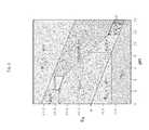
- FIG. 3is a Pourbaix diagram of Iron ions.
- FIG. 4depicts an example control routine within a hybrid flow battery system using the disclosed method.
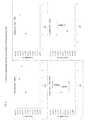
- FIG. 6graphically depicts the Fe potential vs. pH of two electrolytes with different Iron concentrations.
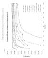
- FIG. 7graphically depicts the Coulombic efficiency to Fe:Acid concentrations of several acids.
- FIG. 8graphically depicts the Coulombic plating efficiency to pH ratio of 4 different acid additives.
- FIG. 9depicts an example embodiment of an electrolyte probe for the disclosed system.
- FIG. 10graphically depicts the color of an example electrolyte as a function of pH.
- the IFBprovides the ability to charge and recharge its electrolytes in contrast to other battery types utilizing non-regenerating electrolytes.
- Chargeis achieved by applying a current across the electrodes.
- the plating electrodemay be coupled to the negative side of a voltage source so that electrons may be delivered to the electrolyte via the redox electrode.
- the Fe 2+is thus oxidized to Fe 3+ and may be dissolved by the electrolyte for subsequent discharge.
- the electrons provided to the negative electrodecan then reduce the Fe 2+ provided by the electrolyte to form Fe 0 at the plating substrate causing it to plate onto the electrode for discharge.
- Dischargecan be sustained while Fe 0 remains in the plating electrolyte for oxidation and the Fe 3+ remains in the redox electrolyte for reduction.
- the lattercan be maintained by increasing the concentration or the volume of the electrolyte to the positive side of the battery to provide Fe 3+ ions via an external tank of the electrolytic chemical.
- the limiting factoris then more commonly the amount Fe 0 solidified onto the negative side of the battery and, consequently, proportional to the surface area and volume of the substrate that the iron may plate on as well as the efficiency of plating.
- Chargeis limited by the same mechanism and solidifies as Fe 0 if ions are available for reduction, it may similarly be aided by an external tank providing additional electrolyte as needed.
- the plating electrolyte chemicalprovides Fe 2+ and the redox electrolyte chemical provides Fe 3+ and Fe 2+ depending on the charge state of the system.
- the use of iron ions in the plating electrolyte and redox electrolyteprovides the ability to use the same electrolytic chemical for both sides of the battery, minimizing the electrolyte cross-contamination that decreases the efficiency of the system eventually and leads to an eventual replacement of the electrolytes.
- low electrolyte reclamation valuecan prove an expensive maintenance cost.
- production of the electrolyteis cost effective using inexpensive materials such as FeCl 2 and FeCl 3 .
- the IFBhas several key issues that contribute to performance and efficiency losses.
- battery efficiency lossesresult from electrolyte crossover through the membrane barrier.
- Ferric ions in the redox electrolyteare driven toward the plating electrolyte by the concentration gradient.
- Ferric ions that penetrate the membrane barriermay react with the iron metal on the negative side, resulting in coulombic efficiency losses.
- Ferric ions that penetrate from redox side (more acidic) to plating side (less acidic)can cause the formation and precipitation of Fe(OH) 3 . This precipitation can foul the organic functional group of an ion exchange membrane or can clog the small pores of the micro-porous membrane. In either case, membrane ohmic resistance rises over time and battery performance degrades.
- Additional coulombic efficiency lossescan be attributed to 1) the reduction of H + and subsequent formation of H 2 2) the H+ ions emitted from the acidic electrolytes reacting with the plated iron metal to form H 2 .
- the side reactioncan result in hydrogen gassing on the negative side of the battery during charging.
- Fe(OH) 3 precipitate formation resulting from oxidation and ferric ion crossovercan cause barrier fouling.
- the resulting separator pore blockagemay cause high battery ohmic resistance and low cell performance.
- the redox electrodeFe 2+ /Fe 3+ couple
- the redox electrodecan experience performance losses over cycles due to a passivating oxide film accumulating on the carbon electrode surface.
- the probemay also be placed inside the reacting portion of the IFB in negative reactor 122 and positive reactor 124 .
- the acid additivemay be in additional tank 106 and 108 . These may contain different additives and be controlled by different routines.
- the IFBmay also have either a positive side additive or a negative side additive and not both.
- the positive side additivemay be accelerated into the positive reactor 122 by positive additive pump 112 ; the negative additive may be accelerated into the negative reactor 124 by negative additive pump 110 .
- the electrolyte additivesmay be pumped into tanks 100 and 102 .
- Pumps 122 and 124may be actuated via a control system communicatively coupled to the pumps.
- the control systemmay be responsive to probe 126 , probe 128 , sensor 102 , sensor 104 , or any combination thereof.
- the electrolytesmay be pumped from the reactor by pumps 130 .
- FIG. 2shows a cross section of an example cell of a hybrid all-iron flow battery.
- the top layershows the redox plate that may be made of carbon or graphite.
- the redox electrodeis adjacent to the redox plate and may be made of graphite.
- the membraneis immediately adjacent to the redox electrode and the plating electrode and separates electrolytes therein.
- An example plating electrodemay include a substrate structure on which the Fe 0 may solidify during charging.
- a next redox plate of an adjacent cellmay be a back face adjacent to the plating electrode.
- FIG. 3shows a Pourbaix diagram that helps to illustrate the electrolyte stability issue.
- the vertical axis of FIG. 3represents the voltage potential with respect to the standard hydrogen electrode, pH is represented on the horizontal axis.
- Fe 2+accepts two electrons to become Fe 0 .
- the reactioncompetes with the reduction of H + and subsequent formation of H 2 .
- the electrolytetends to stabilize at a pH range between 3 and 6 on the negative side of the battery.
- Acidic additivemay be added using the example method depicted in FIG. 4 .
- the electrolytesmay be pumped through their respective electrodes within the IFB at 200 .
- the pH of the batterymay be determined in the electrolyte using a Fe probe to measure the electrolyte potential vs. a reference electrode, such as Ag/AgCl or H 2 electrode, in the plating electrode.
- the pHmay be monitored by measuring the reflective spectra of the electrolyte using an optical sensor via a method that will be further discussed.
- Other pH sensing devices not otherwise specifiedmay also be used for the pH determination.
- Sensors monitoring temperature and other operating conditionsmay also be communicatively coupled to a control system and used in conjunction with electrolyte pH within the disclosed method. Note that the information provided by these additional sensors may be included in the operational definition of the term “pH” when used as a system control variable herein.
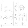
- FIG. 5A few examples of the complex structure with ferrous/ferric ions are shown in FIG. 5 .
- the equilibrium potentials of an iron surface in IFB electrolytes at various solution pH and different Fe-to-organic-acid ratiosare shown in FIG. 6 .
- Fe equilibrium potentialdecreases slightly between pH 1 to pH 4 and then the equilibrium potential rises significantly with pH. The increase is due to thin layers of iron oxide that form on the iron surface at higher pH levels.
- the battery plating equilibrium potentialcould be 50 mV worse, and as the result, the IFB performance could be 50 mV worse.
- the Fe potential as a function of pHis graphically represented in FIG. 6 .
- the relationship depicted in FIG. 6may be used by the control system to meter pH in the disclosed system.
- the control systemmay measure Fe potential and determine pH using the relationship depicted in FIG. 6 , or a similar relationship for a corresponding Fe concentration.
- the pH measurementmay be used in the method described in FIG. 4 .
- the control systemmay initiate or increase the addition of an acid additive in order to achieve a desired Fe potential determined by the relationship depicted in FIG. 6 .
- the coulombic efficiency of Fe plating using these organic acids at various ratiosis presented in FIG. 7 .
- the relationship presented in FIG. 7may, in some of the disclosed embodiments, be determinative of the chemical composition of the acid additives employed. For example, if a coulombic plating efficiency above 85% is desired, and malonic acid is used as the acid additive, the control system may maintain a Fe/Acid ratio above 20%. The ratio may be maintained via a predetermined maximum amount of acid additive that may be based on the volume and composition of the electrolyte.
- boric acid, ascorbic acid, L-ascorbic acid, glycolic acid, acetic acid and malonic acidall show high Fe plating coulombic efficiencies at high Fe to acid ratios. As more acid (lower Fe:acid ratio) were added to the electrolyte, plating coulombic efficiencies drops. This results from the formation of carbon from the organic acids during charging. This chart was used to define the range of organic acids used in the battery.
- FIG. 8graphically depicts the coulombic efficiency of iron plating for different plating solution pH levels.
- acetic acid and glycolic acid(not shown) alone cannot stabilize the crossover ferric ion at high pH.
- ascorbic or isoascorbic acid aloneis not ideal to be used as the organic acid because of C formation leading to reduced coulombic efficiency. Carbon formation was detected through electron microscope scanning on iron film plated from a bath with ascorbic acid only.
- combination of organic acid additivesmay be utilized to achieve the optimal iron plating bath for performance, efficiency, and stability.
- an electrolyte solution of FeCl 2 and NaCla first acid (such as boric acid) can be added for H 2 side reaction suppression and high coulombic efficiencies.
- a second acidsuch as ascorbic acid
- a third acidsuch as glycolic acid
- an example batterymay use the iron potential probe shown in FIG. 9 .
- the probemay be produced with a clean iron wire in conjunction with a reference electrode such as an Ag/AgCl wire or a H 2 electrode.
- the probecan be placed in the electrolyte tank where Fe potential may be monitored over time.
- Fe potential of the electrolytedrifts up, a calculated small amount of acid can be added to the electrolyte to adjust its pH.
- the electrolytescan be more precisely maintained at the ideal pH and composition for redox.
- the embodiment in FIG. 9is an Fe potential probe that may be used to measure the potential on Fe 0 and a corresponding pH within the plating electrode.
- the potential probemay have inert electrode 206 that may be a wire made of iron or another inert or quasi-inert metal such that the electrons in the metal will not oxidize or will oxidize at a known rate.
- Reference electrode 200may be a wire containing silver (Ag) and an Ag salt such as AgCl or a H 2 reference electrode.
- the Fe probemay be placed in the plating electrolyte to measure solution potential on Fe. Further, Fe may represent the solution potential and pH for the plating side of the battery.
- the electrodesmay be electrically isolated from each other by insulator 202 that may be made of any material with low or no conductivity. Heat shrink 200 acts to keep the Fe and the reference electrode at a set distance.
- the pH of the electrolytesmay also be monitored by a sensor that may be used independently, or in combination with, the probe.
- the optical sensormay measure the absorption spectrum of ambient light through the liquid to determine the corresponding pH.
- the optical sensorcan also be used to monitor battery state of charge if chelating organic acid is added to the electrolyte to increase iron ion stabilities. This is because chelated iron complex shows different color at different pHs. For example, if ascorbic acid is used as the chelating agent, the iron solution color goes from green to violet and then black from pH of 2 to pH of 6.
- the control system communicatively coupled to the sensormay determine the pH using the pH to color relationship depicted in FIG. 10 .
- the pH-color relationship depicted graphicallyin which the vertical axis represents the average number of H+ bound per carbon atom and the horizontal axis is a logarithmic representation of h.
- the solutionis green or pale, as the number of free H+ increases (increasing pH) the solution becomes violet and eventually black when the average number of free H+ is highest.
- the pH of the electrolytemay be determined.
- white lightmay be incident on the surface of the electrolyte.
- a spectroscopemay be utilized within the sensor to determine the wavelength of light reflected by the electrolyte. If a reflected and/or transmitted wavelength is found to be, for instance, less than 450 nm (corresponding to a violet hue) acid additive may be added to the solution to lower the electrolyte pH. Further, the spectroscope may continue to monitor the absorption spectra of the electrolyte and if the reflected and/or transmitted wavelength is found to be above a threshold, such as 510 nm (corresponding to a green hue), the addition of acid additive may be terminated.
- a thresholdsuch as 510 nm (corresponding to a green hue
- the pH changemay result in up to 100 mV ‘apparent’ performance loss of the battery due to Fe equilibrium potential drifting up with higher pH level.
- an embodiment of the disclosed Fe Potential Probe or optical sensorsuch as those described above, may be used to monitor battery state of charge as well as the electrolytes' pH level.
- the operation window for the plating electrolyte of the batteryis between pH of 3 and 4. Therefore, in an embodiment, when either a Fe Potential Probe or an optical sensor shows a pH level above 4, a small, pre-calculated amount of acid may be added to the plating electrolyte solution to return the plating electrode to an optimal pH range. As a result, the battery performance may be stabilized.
Landscapes
- Life Sciences & Earth Sciences (AREA)
- Engineering & Computer Science (AREA)
- Manufacturing & Machinery (AREA)
- Sustainable Development (AREA)
- Sustainable Energy (AREA)
- Chemical & Material Sciences (AREA)
- Chemical Kinetics & Catalysis (AREA)
- Electrochemistry (AREA)
- General Chemical & Material Sciences (AREA)
- Fuel Cell (AREA)
Abstract
Description
- This application claims the benefit under 35 U.S.C. 119(e) of U.S. Provisional Patent Application No. 61/778,143, filed Mar. 12, 2013 and entitled METHODS TO PREPARE STABLE ELECTROLYTES FOR ALL IRON REDOX FLOW BATTERIES, the entirety of which is incorporated herein by reference for all purposes.
- The reduction-oxidation (redox) flow battery is an electrochemical storage device that stores energy in a chemical form and converts the stored chemical energy to an electrical form via spontaneous reverse redox reactions. The reaction in a flow battery is reversible, so conversely, the dispensed chemical energy can be restored by the application of an electrical current inducing the reversed redox reactions. A single redox flow battery cell generally includes a negative electrode, a membrane barrier, a positive electrode, and electrolytes containing electro-active materials. Multiple cells may be combined in series or parallel to create a higher voltage or current in a flow battery. Electrolytes are typically stored in external tanks and are pumped through both sides of the battery. When a charge current is applied, electrolytes lose electron(s) at the positive electrode and gain electron(s) at the negative electrode. The membrane barrier prevents the positive electrolyte and negative electrolyte from mixing while allowing ionic conductance. When a discharge current is applied, reverse redox reactions occur on the electrodes. The electrical potential difference across the battery is maintained by chemical redox reactions within the electrolytes and can induce a current through a conductor while the reactions are sustained. The amount of energy stored by a redox battery is limited by the amount of electro-active material available in electrolytes for discharge, depending on the total volume of electrolytes and the solubility of the electro-active materials.
- Hybrid flow batteries are distinguished by the deposit of one or more of the electro-active materials as a solid layer on an electrode. Hybrid batteries may, for instance, include a chemical that plates as a solid on a substrate throughout the charge reaction and its discharged species may be dissolved by the electrolyte throughout discharge. In hybrid battery systems, the energy stored by the redox battery may be limited by the amount of metal plated during charge and may accordingly be determined by the efficiency of the plating system as well as the available volume and surface area to plate.
- In a hybrid flow battery system the negative electrode may be referred to as the plating electrode and the positive electrode may be referred to as the redox electrode. The electrolyte within the plating side of the battery may be referred to as the plating electrolyte and the electrolyte on the redox side of the battery may be referred to as the redox electrolyte.
- Anode refers to the electrode where electro-active material loses electrons. During charge, the negative electrode gains electrons and is therefore the cathode of the electrochemical reaction. During discharge, the negative electrode loses electrons and is therefore the anode of the reaction. Therefore, during charge, the plating electrolyte and plating electrode may be respectively referred to as the catholyte and cathode of the electrochemical reaction; the redox electrolyte and the redox electrode may be respectively referred to as the anolyte and anode of the electrochemical reaction. Alternatively, during discharge, the plating electrolyte and plating electrode may be respectively referred to as the anolyte and anode of the electrochemical reaction, the redox electrolyte and the redox electrode may be respectively referred to as the catholyte and cathode of the electrochemical reaction.
- One example of a hybrid redox flow battery uses iron as an electrolyte for reactions wherein on the negative electrode Fe2+ receives two electrons and deposits as iron metal during charge and iron metal loses two electrons and re-dissolves as Fe2+ during discharge. On the positive electrode two Fe2+ lose two electrons to form two Fe3+ during charge and during discharge two Fe3+ gains two electrons to form two Fe2+:
Fe2++2e−Fe0(Negative Electrode)
2Fe2+2Fe3++2e− (Positive Electrode).- The electrolyte used for this reaction is readily available and can be produced at low costs (such as FeCl2). It also has a high reclamation value because the same electrolyte can be used for the plating electrolyte and the redox electrolyte, consequently eliminating the possibility of cross contamination. Unlike other compounds used in hybrid redox flow batteries, iron does not form dendrites during plating and thus offers stable electrode morphology. Further, iron redox flow batteries do not require the use of toxic raw materials and operate at a relatively neutral pH unlike similar redox flow battery electrolytes. Accordingly, it is the least environmentally hazardous of all current advanced battery systems in production.
- However, the above system has disadvantages that limit its practicality in commercial applications. One of these disadvantages is the low cycling performance and poor efficiency of these batteries resulting from a discrepancy in the pH ranges at which the negative and redox electrolytes tend to stabilize. To minimize iron corrosion reactions and to increase iron plating efficiency, a pH between 3 and 4 is desired for the iron plating reaction. However, a pH less than 1 is desired for the ferrous and ferric ion redox reaction to promote redox reaction kinetics and to minimize hydroxide formation.
- Concentration gradients across the membrane barrier separating the electrolytes can cause electrolyte crossover. The Fe3+ contamination from the redox side (more acidic) to plating side (less acidic) can cause the formation and precipitation of Fe(OH)3. This precipitate can foul the organic functional group of an ion exchange membrane or can clog the small pores of the micro-porous membrane. In either case, membrane ohmic resistance rises over time and battery performance degrades.
- The inventors recognized that the formation of the Fe(OH)3precipitate could be reduced by the addition of chemical chelating agents in the form of organic compounds. These organic compounds could form complex compounds with Fe3+ which has crossed over from redox side to plating side. These complex compounds are soluble in less acidic environment, and thus stabilize the ferric ions. Further, the colors and potentials of these complex compounds change with solution pH. Therefore, by monitoring the electrolyte pH via an optical sensor and/or electrochemical probe, the addition of chemical additives may be metered so as to achieve and maintain the desired pH in the electrolyte to prevent precipitation and preserve coulombic efficiency.
FIG. 1 is an example embodiment of the disclosed hybrid flow battery system.FIG. 2 shows a cross section of the disclosed hybrid flow battery system ofFIG. 1 .FIG. 3 is a Pourbaix diagram of Iron ions.FIG. 4 depicts an example control routine within a hybrid flow battery system using the disclosed method.FIG. 5 illustrates example compounds that formed from Iron and 4 different acidic compounds.FIG. 6 graphically depicts the Fe potential vs. pH of two electrolytes with different Iron concentrations.FIG. 7 graphically depicts the Coulombic efficiency to Fe:Acid concentrations of several acids.FIG. 8 graphically depicts the Coulombic plating efficiency to pH ratio of 4 different acid additives.FIG. 9 depicts an example embodiment of an electrolyte probe for the disclosed system.FIG. 10 graphically depicts the color of an example electrolyte as a function of pH.- As discussed above, the plating electrolyte used in the all iron redox flow battery (IFB) may provide a sufficient amount of Fe2+ so that, during charge, it can accept two electrons from the negative electrode to form Fe0and solidify onto a substrate. During discharge, the solidified Fe0may then lose two electrons, ionizing into Fe2+ and be dissolved back into the electrolyte. The equilibrium potential of the above reaction is −0.44V and thus this reaction provides a negative terminal for the desired system. On the positive side of the IFB, the electrolyte may provide Fe2+ during charge which loses electron and oxidizes to Fe3+. During discharge, Fe3+ provided by the electrolyte becomes Fe2+ by absorbing an electron provided by the electrode. The equilibrium potential of this reaction is +0.77V, creating a more positive terminal for the desired system.
- The IFB provides the ability to charge and recharge its electrolytes in contrast to other battery types utilizing non-regenerating electrolytes. Charge is achieved by applying a current across the electrodes. The plating electrode may be coupled to the negative side of a voltage source so that electrons may be delivered to the electrolyte via the redox electrode. The Fe2+ is thus oxidized to Fe3+ and may be dissolved by the electrolyte for subsequent discharge. The electrons provided to the negative electrode can then reduce the Fe2+ provided by the electrolyte to form Fe0at the plating substrate causing it to plate onto the electrode for discharge.
- Discharge can be sustained while Fe0remains in the plating electrolyte for oxidation and the Fe3+ remains in the redox electrolyte for reduction. The latter can be maintained by increasing the concentration or the volume of the electrolyte to the positive side of the battery to provide Fe3+ ions via an external tank of the electrolytic chemical. The limiting factor is then more commonly the amount Fe0solidified onto the negative side of the battery and, consequently, proportional to the surface area and volume of the substrate that the iron may plate on as well as the efficiency of plating. Charge is limited by the same mechanism and solidifies as Fe0if ions are available for reduction, it may similarly be aided by an external tank providing additional electrolyte as needed.
- In the above reaction the plating electrolyte chemical provides Fe2+ and the redox electrolyte chemical provides Fe3+ and Fe2+ depending on the charge state of the system. The use of iron ions in the plating electrolyte and redox electrolyte provides the ability to use the same electrolytic chemical for both sides of the battery, minimizing the electrolyte cross-contamination that decreases the efficiency of the system eventually and leads to an eventual replacement of the electrolytes. In similar systems, low electrolyte reclamation value can prove an expensive maintenance cost. Further, production of the electrolyte is cost effective using inexpensive materials such as FeCl2and FeCl3.
- The electron configuration of iron allows it to solidify into a generally uniform solid structure on the substrate. In metals commonly used in similar redox batteries (such as Zinc) the solid structure may form dendrites during plating. The stable electrode morphology of the IFB increases the efficiency of the battery in comparison to other flow batteries. Further, no toxic raw materials are used in the battery and it utilizes electrolytes that generally operate at a pH between 1 and 3. Consequently, IFBs are the least environmentally hazardous of advanced battery systems currently in production.
- However, the IFB has several key issues that contribute to performance and efficiency losses. In particular, battery efficiency losses result from electrolyte crossover through the membrane barrier. Ferric ions in the redox electrolyte are driven toward the plating electrolyte by the concentration gradient. Ferric ions that penetrate the membrane barrier may react with the iron metal on the negative side, resulting in coulombic efficiency losses. Ferric ions that penetrate from redox side (more acidic) to plating side (less acidic) can cause the formation and precipitation of Fe(OH)3. This precipitation can foul the organic functional group of an ion exchange membrane or can clog the small pores of the micro-porous membrane. In either case, membrane ohmic resistance rises over time and battery performance degrades. Additional coulombic efficiency losses can be attributed to 1) the reduction of H+ and subsequent formation of H22) the H+ ions emitted from the acidic electrolytes reacting with the plated iron metal to form H2. The side reaction can result in hydrogen gassing on the negative side of the battery during charging.
- Fe(OH)3precipitate formation resulting from oxidation and ferric ion crossover can cause barrier fouling. The resulting separator pore blockage may cause high battery ohmic resistance and low cell performance. Additionally, the redox electrode (Fe2+/Fe3+ couple) can experience performance losses over cycles due to a passivating oxide film accumulating on the carbon electrode surface.
FIG. 1 shows an example embodiment of an IFB. The plating electrolyte may be stored in platingelectrolyte tank 100, the redox electrolyte may be stored inredox electrolyte tank 101. The plating electrolyte and redox electrolyte may be a suitable salt dissolved in water, such as FeCl2or FeCl3. Both the plating electrolyte and redox electrolyte may use the same salt at different molar concentrations, a feature of the IFB not available in batteries with different reactive compounds. Both tanks may be fluidically coupled to thepositive reactor 124 andnegative reactor 122 of the fuel cell. Separating the negative and positive reactors and their respective electrolytes isbarrier 120. The barrier may be embodied as a membrane barrier, such as an ion exchange membrane or a microporous membrane, placed between the redox electrolyte and plating electrolyte to prevent electrolyte cross-over and provide ionic conductivity.Sensors Probes negative reactor 122 andpositive reactor 124. The acid additive may be inadditional tank positive reactor 122 by positiveadditive pump 112; the negative additive may be accelerated into thenegative reactor 124 by negativeadditive pump 110. Alternately, the electrolyte additives may be pumped intotanks Pumps probe 128,sensor 102,sensor 104, or any combination thereof. The electrolytes may be pumped from the reactor by pumps130.FIG. 2 shows a cross section of an example cell of a hybrid all-iron flow battery. The top layer shows the redox plate that may be made of carbon or graphite. The redox electrode is adjacent to the redox plate and may be made of graphite. The membrane is immediately adjacent to the redox electrode and the plating electrode and separates electrolytes therein. An example plating electrode may include a substrate structure on which the Fe0may solidify during charging. In IFB's made with multiple cells, a next redox plate of an adjacent cell may be a back face adjacent to the plating electrode.- Cycling performance losses in the IFB may be attributed to the nature of the electrolytes' stability.
FIG. 3 shows a Pourbaix diagram that helps to illustrate the electrolyte stability issue. The vertical axis ofFIG. 3 represents the voltage potential with respect to the standard hydrogen electrode, pH is represented on the horizontal axis. During charge, Fe2+ accepts two electrons to become Fe0. However, the reaction competes with the reduction of H+ and subsequent formation of H2. As a result, the electrolyte tends to stabilize at a pH range between 3 and 6 on the negative side of the battery. - During charge, the Fe2+ on the positive side of the battery loses one electron to form Fe3+, an ion with a much lower logarithmic acid disassociation constant (pKa) than that of Fe2+. Therefore, as more ferrous ions are oxidized to ferric ions, the electrolyte tends to stabilize at a pH closer to 1.
- Concentration gradients on either side of the barrier during battery operation drive an amount of Fe3+ over from redox electrolyte to plating electrolyte. The drastic change in pH from plating electrolyte to redox electrolyte (from 1 to 3-6) causes FeOH2+ and Fe(OH)3species to form and precipitate. These precipitates degrade the membrane by poisoning the organic functional group of an ion exchange membrane or clogging the small pores of the microporous membrane. As the result, the battery's ohmic resistance rises. Precipitate may be removed by washing the battery with acid, but the constant maintenance limits the batteries use in commercial applications, it also relies upon a regular preparation of electrolyte. However, the disclosed method suppresses the above reactions by adding specific organic acids to the electrolytes in response to indications of an electrolyte pH indicative of, and contributing to, these reactions.
- Acidic additive may be added using the example method depicted in
FIG. 4 . The electrolytes may be pumped through their respective electrodes within the IFB at200. At202 the pH of the battery may be determined in the electrolyte using a Fe probe to measure the electrolyte potential vs. a reference electrode, such as Ag/AgCl or H2electrode, in the plating electrode. Alternately, the pH may be monitored by measuring the reflective spectra of the electrolyte using an optical sensor via a method that will be further discussed. Other pH sensing devices not otherwise specified may also be used for the pH determination. Sensors monitoring temperature and other operating conditions may also be communicatively coupled to a control system and used in conjunction with electrolyte pH within the disclosed method. Note that the information provided by these additional sensors may be included in the operational definition of the term “pH” when used as a system control variable herein. - In the disclosed system, the sensors and/or probes may communicate to a control system the pH of the electrolyte. If the pH of the plating electrolyte is found to be above a threshold, such as pH>4, the control system may actuate the release of a preset amount of a prepared acid that may be added to the plating electrolyte at204. If the pH of the redox electrolyte is found to be above a threshold, such as pH>1, the control system may actuate the release of a preset amount of a prepared acid to the redox electrolyte. The acid additive added to the negative and positive sides may be the same or different and may include but are not limited to hydrochloric acid, boric acid, ascorbic acid, acetic acid, malic acid, lactic acid, citric acid, tartaric acid, isoascorbic acid, malonic acid, glycolic acid, or any combination thereof. The process may return back to202 to again measure the pH, the process may repeat until the pH falls below the threshold. If the pH is below the threshold the IFB may continue to charge or discharge.
- The disclosed embodiment achieves suppression of the aforementioned problematic reactions by adding specific chemicals (acid additives) to the electrolytes. The acid additives to the electrolytes may stabilize Fe3+ crossover from the redox electrolyte to the plating electrolyte, thus the acid additives used in the embodiment have specific chemical properties. Chemical additives that are organic chemicals with short chains (<6C) and with —OH and/or —COOH groups are sought to stabilize the ferric/ferrous ions by forming large complexes with these ions. A shorter carbon chain is sought to minimize the negative effect these organic acids may have on overall battery coulombic efficiency because these organic acids may have the side reaction of carbon formation during battery charging. The acids studied for addition and some of their properties are listed in table 1 below.
TABLE 1 Organic Acids Tested for Stabilizing IFB Electrolytes Efficiency % Acid Equation pH > 2.5 Carbon g/mol pKa Notes Boric H3BO3 64.0 9.237 Reported for H2 suppression L-Ascorbic C6H8O6 176.12 4.10 C-A bath, but also used with Citric acid Glycolic C2H4O3 93% 0.00% 79.050 3.83 Testing at 10 mA/cm2. Grayish dull, rough surface L-lactic C3H6O3 79% 0.00% 90.080 3.86 Testing at 10 mA/cm2. Grayish dull, rough surface L-Malic C4H6O5 90% 0.60% 134.090 3.40 Testing at 10 mA/cm2. black and bright surface. Black oxides precipitated at current densities above 33 mA/cm2. Black color was only due to surface film L-Tartaric C4H6O6 >90% >2.5% 150.087 2.95 Testing at 10 mA/cm2. burnt. Lots of black precipitates Citric C6H8O7 83% 1.00% 192.124 3.09 Testing at 10 mA/cm2. black and bright surface. Black oxides precipitated at current densities above 39 mA/cm2. Black color was only due to surface film Oxalic C2H2O4 95% 0.13% 90.030 1.25 Testing at 10 mA/cm2. Grayish dull, rough surface Malonic C3H4O4 95% 0.13% 104.060 2.83 Testing at 10 mA/cm2. Grayish dull, rough surface Acetic C2H4O2 95% 0.10% 60.050 4.76 Testing at 10 mA/cm2. Grayish dull, rough surface Butonic C4H8O2 95% .0.15% 88.110 4.82 Testing at 10 mA/cm2. Grayish dull, rough surface Stinky Erythorbic C6H8O6 176.18 2.1 In patent as additive - A few examples of the complex structure with ferrous/ferric ions are shown in
FIG. 5 . TABLE 2 Organic-Ferrous/Ferric Stability with pH Ascorbic Isoascorbic Malonic pH Acetic Acid Acid Acid acid >2 No No No No Precipitation Precipitation Precipitation Precipitation >3 Precipitation No No No Precipitation Precipitation Precipitation >4 Precipitation No No No Precipitation Precipitation Precipitation - The inventors determined electrolyte stability with these additives and Fe plating coulombic efficiencies using an H-Cell setup. Baths were prepared from reagent-grade chemicals and deionized distilled water that contained 0.5 mol/l FeCl2and various ratio of one of the organic acids. Bath initial pH ranged from 2 to 3 and they were not adjusted. A graphite rod was used as the plating electrode and a graphite plate was used as the redox electrode. Electrodeposition was carried out at a constant current density of 10 mA/cm2. The bath was kept at room temperature. The baths were not agitated because bath agitation decreases current efficiency since the H reduction current attains the diffusion limited current at a more noble potential than Fe deposition and therefore increases with agitation. Current efficiency was evaluated from the weight of the deposits obtained at a given amount of charge assuming that only Fe was deposited from Fe2+; this assumption is valid because of the relatively low carbon and oxygen content in the deposits.
- The equilibrium potentials of an iron surface in IFB electrolytes at various solution pH and different Fe-to-organic-acid ratios are shown in
FIG. 6 . As shown, Fe equilibrium potential decreases slightly betweenpH 1 topH 4 and then the equilibrium potential rises significantly with pH. The increase is due to thin layers of iron oxide that form on the iron surface at higher pH levels. When running an IFB, if the electrolyte pH changes from 4 to 5, the battery plating equilibrium potential could be 50 mV worse, and as the result, the IFB performance could be 50 mV worse. - The Fe potential as a function of pH is graphically represented in
FIG. 6 . The relationship depicted inFIG. 6 may be used by the control system to meter pH in the disclosed system. In an embodiment, the control system may measure Fe potential and determine pH using the relationship depicted inFIG. 6 , or a similar relationship for a corresponding Fe concentration. The pH measurement may be used in the method described inFIG. 4 . In other embodiments, the control system may initiate or increase the addition of an acid additive in order to achieve a desired Fe potential determined by the relationship depicted inFIG. 6 . - The coulombic efficiency of Fe plating using these organic acids at various ratios is presented in
FIG. 7 . The relationship presented inFIG. 7 may, in some of the disclosed embodiments, be determinative of the chemical composition of the acid additives employed. For example, if a coulombic plating efficiency above 85% is desired, and malonic acid is used as the acid additive, the control system may maintain a Fe/Acid ratio above 20%. The ratio may be maintained via a predetermined maximum amount of acid additive that may be based on the volume and composition of the electrolyte. As shown inFIG. 7 , boric acid, ascorbic acid, L-ascorbic acid, glycolic acid, acetic acid and malonic acid all show high Fe plating coulombic efficiencies at high Fe to acid ratios. As more acid (lower Fe:acid ratio) were added to the electrolyte, plating coulombic efficiencies drops. This results from the formation of carbon from the organic acids during charging. This chart was used to define the range of organic acids used in the battery. - Furthermore, the same H-cell tests were performed on several Fe:organic acid ratios to study the crossover ferric ion stability at various pH of the plating side as shown in
FIG. 8 . In some embodiments of the disclosed system, the results inFIG. 8 were used by the control system to determine the desired pH of the electrolytic solution to achieve a desired coulombic efficiency. As an example,FIG. 8 graphically depicts the coulombic efficiency of iron plating for different plating solution pH levels. As shown in Table 2 andFIG. 8 , acetic acid and glycolic acid (not shown) alone cannot stabilize the crossover ferric ion at high pH. However, ascorbic or isoascorbic acid alone is not ideal to be used as the organic acid because of C formation leading to reduced coulombic efficiency. Carbon formation was detected through electron microscope scanning on iron film plated from a bath with ascorbic acid only. - Therefore, in some embodiments of the disclosed system, combination of organic acid additives may be utilized to achieve the optimal iron plating bath for performance, efficiency, and stability. In an example embodiment, an electrolyte solution of FeCl2and NaCl, a first acid (such as boric acid) can be added for H2side reaction suppression and high coulombic efficiencies. Additionally, a second acid (such as ascorbic acid) can be added for ferric ion stability and a third acid (such as glycolic acid) can be added for minimizing carbon formation.
- To mitigate electrolyte sensitivity to pH, an example battery may use the iron potential probe shown in
FIG. 9 . The probe may be produced with a clean iron wire in conjunction with a reference electrode such as an Ag/AgCl wire or a H2electrode. The probe can be placed in the electrolyte tank where Fe potential may be monitored over time. When Fe potential of the electrolyte drifts up, a calculated small amount of acid can be added to the electrolyte to adjust its pH. By metering the amount of electrolyte additive added in response to the presiding pH, the electrolytes can be more precisely maintained at the ideal pH and composition for redox. - The embodiment in
FIG. 9 is an Fe potential probe that may be used to measure the potential on Fe0and a corresponding pH within the plating electrode. The potential probe may haveinert electrode 206 that may be a wire made of iron or another inert or quasi-inert metal such that the electrons in the metal will not oxidize or will oxidize at a known rate.Reference electrode 200 may be a wire containing silver (Ag) and an Ag salt such as AgCl or a H2reference electrode. For example, in an embodiment, the Fe probe may be placed in the plating electrolyte to measure solution potential on Fe. Further, Fe may represent the solution potential and pH for the plating side of the battery. The electrodes may be electrically isolated from each other byinsulator 202 that may be made of any material with low or no conductivity. Heat shrink200 acts to keep the Fe and the reference electrode at a set distance. - In other embodiments of the disclosed system, the pH of the electrolytes may also be monitored by a sensor that may be used independently, or in combination with, the probe. In an embodiment, the optical sensor may measure the absorption spectrum of ambient light through the liquid to determine the corresponding pH. The optical sensor can also be used to monitor battery state of charge if chelating organic acid is added to the electrolyte to increase iron ion stabilities. This is because chelated iron complex shows different color at different pHs. For example, if ascorbic acid is used as the chelating agent, the iron solution color goes from green to violet and then black from pH of 2 to pH of 6.
- The control system communicatively coupled to the sensor may determine the pH using the pH to color relationship depicted in
FIG. 10 . Here the pH-color relationship depicted graphically, in which the vertical axis represents the average number of H+ bound per carbon atom and the horizontal axis is a logarithmic representation of h. As shown, at low pH (higher number of H+ bound per C) the solution is green or pale, as the number of free H+ increases (increasing pH) the solution becomes violet and eventually black when the average number of free H+ is highest. By measuring the wavelength of ambient light or a light from a known source through and/or reflected by the electrolyte, the pH of the electrolyte may be determined. - In an example embodiment, white light may be incident on the surface of the electrolyte. A spectroscope may be utilized within the sensor to determine the wavelength of light reflected by the electrolyte. If a reflected and/or transmitted wavelength is found to be, for instance, less than 450 nm (corresponding to a violet hue) acid additive may be added to the solution to lower the electrolyte pH. Further, the spectroscope may continue to monitor the absorption spectra of the electrolyte and if the reflected and/or transmitted wavelength is found to be above a threshold, such as 510 nm (corresponding to a green hue), the addition of acid additive may be terminated.
- On the negative side of the IFB, during charge Fe2+ accepts two electrons and forms Fe0. The competing reaction on the negative side of the battery (H+ accepts one electron and forms H2) results in the tendency of the electrolyte on the negative side of the IFB to rise over cycles from pH of 2 to pH of 6 thus embodiments of the disclosed system may use the probe and sensors above to monitor pH change.
- As shown previously in
FIG. 6 , the pH change may result in up to 100 mV ‘apparent’ performance loss of the battery due to Fe equilibrium potential drifting up with higher pH level. To mitigate performance loss, an embodiment of the disclosed Fe Potential Probe or optical sensor, such as those described above, may be used to monitor battery state of charge as well as the electrolytes' pH level. - The operation window for the plating electrolyte of the battery is between pH of 3 and 4. Therefore, in an embodiment, when either a Fe Potential Probe or an optical sensor shows a pH level above 4, a small, pre-calculated amount of acid may be added to the plating electrolyte solution to return the plating electrode to an optimal pH range. As a result, the battery performance may be stabilized.
- It will be appreciated that the configurations and routines disclosed herein are exemplary in nature, and that these specific embodiments are not to be considered in a limiting sense, because numerous variations are possible. For example, the above technology may be applied to other flow battery types. The subject matter of the present disclosure includes all novel and nonobvious combinations and subcombinations of the various systems and configurations, and other features, functions, and/or properties disclosed herein.
- The following claims particularly point out certain combinations and subcombinations regarded as novel and nonobvious. These claims may refer to “an” element or “a first” element or the equivalent thereof. Such claims should be understood to include incorporation of one or more such elements, neither requiring nor excluding two or more such elements. Other combinations and subcombinations of the disclosed features, functions, elements, and/or properties may be claimed through amendment of the present claims or through presentation of new claims in this or a related application.
- Such claims, whether broader, narrower, equal, or different in scope to the original claims, also are regarded as included within the subject matter of the present disclosure.

Claims (12)
Priority Applications (3)
| Application Number | Priority Date | Filing Date | Title |
|---|---|---|---|
| US14/201,244US9865895B2 (en) | 2013-03-12 | 2014-03-07 | Methods to prepare stable electrolytes for iron redox flow batteries |
| US15/436,593US10586996B2 (en) | 2013-03-12 | 2017-02-17 | Electrolytes for iron flow battery |
| US15/711,879US10403919B2 (en) | 2013-03-12 | 2017-09-21 | Methods to prepare stable electrolytes for iron redox flow batteries |
Applications Claiming Priority (2)
| Application Number | Priority Date | Filing Date | Title |
|---|---|---|---|
| US201361778143P | 2013-03-12 | 2013-03-12 | |
| US14/201,244US9865895B2 (en) | 2013-03-12 | 2014-03-07 | Methods to prepare stable electrolytes for iron redox flow batteries |
Related Child Applications (2)
| Application Number | Title | Priority Date | Filing Date |
|---|---|---|---|
| US15/436,593Continuation-In-PartUS10586996B2 (en) | 2013-03-12 | 2017-02-17 | Electrolytes for iron flow battery |
| US15/711,879DivisionUS10403919B2 (en) | 2013-03-12 | 2017-09-21 | Methods to prepare stable electrolytes for iron redox flow batteries |
Publications (2)
| Publication Number | Publication Date |
|---|---|
| US20140272493A1true US20140272493A1 (en) | 2014-09-18 |
| US9865895B2 US9865895B2 (en) | 2018-01-09 |
Family
ID=51528419
Family Applications (2)
| Application Number | Title | Priority Date | Filing Date |
|---|---|---|---|
| US14/201,244Active2036-02-25US9865895B2 (en) | 2013-03-12 | 2014-03-07 | Methods to prepare stable electrolytes for iron redox flow batteries |
| US15/711,879ActiveUS10403919B2 (en) | 2013-03-12 | 2017-09-21 | Methods to prepare stable electrolytes for iron redox flow batteries |
Family Applications After (1)
| Application Number | Title | Priority Date | Filing Date |
|---|---|---|---|
| US15/711,879ActiveUS10403919B2 (en) | 2013-03-12 | 2017-09-21 | Methods to prepare stable electrolytes for iron redox flow batteries |
Country Status (1)
| Country | Link |
|---|---|
| US (2) | US9865895B2 (en) |
Cited By (20)
| Publication number | Priority date | Publication date | Assignee | Title |
|---|---|---|---|---|
| US9553465B2 (en)* | 2014-04-21 | 2017-01-24 | Palo Alto Research Center Incorporated | Battery management based on internal optical sensing |
| DE102015011688A1 (en)* | 2015-09-14 | 2017-03-16 | Christian Gutsche | Accumulator with at least two electrodes, with at least one electrolyte and with at least one electrolyte container for receiving at least one electrolyte |
| US9677916B2 (en) | 2014-07-15 | 2017-06-13 | Palo Alto Research Center Incorporated | Energy system monitoring |
| US20170179516A1 (en)* | 2013-03-12 | 2017-06-22 | Ess Tech, Inc. | Electrolytes for iron flow battery |
| CN107978775A (en)* | 2017-12-22 | 2018-05-01 | 河北地标电力科技有限公司 | A kind of iron-based redox flow battery system |
| WO2018152256A1 (en)* | 2017-02-17 | 2018-08-23 | Ess Tech, Inc. | Electrolytes for iron flow battery |
| EP3432402A1 (en)* | 2017-07-18 | 2019-01-23 | Siemens Aktiengesellschaft | Method for operating at least one electrical energy storage device and electrical energy storage device |
| CN109659588A (en)* | 2018-12-10 | 2019-04-19 | 合肥沃工电气自动化有限公司 | A kind of vanadium cell self-starting progress control method |
| US10317256B2 (en) | 2017-04-14 | 2019-06-11 | Palo Alto Research Center Incorporated | Monitoring transportation systems |
| US10403922B2 (en) | 2014-07-23 | 2019-09-03 | Palo Alto Research Center Incorporated | Battery with embedded fiber optic cable |
| US10403919B2 (en) | 2013-03-12 | 2019-09-03 | Ess Tech, Inc. | Methods to prepare stable electrolytes for iron redox flow batteries |
| US10446886B2 (en) | 2014-07-23 | 2019-10-15 | Palo Alto Research Center Incorporated | Embedded fiber optic cables for battery management |
| US20200127466A1 (en)* | 2018-10-17 | 2020-04-23 | Ess Tech, Inc. | System and method for operating an electrical energy storage system |
| JP2022506414A (en)* | 2018-11-02 | 2022-01-17 | イーエスエス テック インコーポレーテッド | System and method for determining the state of charge of an electric energy storage device |
| US20220134292A1 (en)* | 2020-11-04 | 2022-05-05 | Uop Llc | Ionically conductive thin film composite membranes for energy storage applications |
| US20220149417A1 (en)* | 2017-04-28 | 2022-05-12 | Ess Tech, Inc. | Flow battery cleansing cycle to maintain electrolyte health and system performance |
| EP4016681A1 (en) | 2020-12-15 | 2022-06-22 | VoltStorage GmbH | Rebalancing system of a fe/fe redox flow battery |
| CN116072969A (en)* | 2023-03-08 | 2023-05-05 | 金阳(泉州)新能源科技有限公司 | Electrolyte, preparation method thereof and lithium manganate battery |
| CN119275319A (en)* | 2024-08-27 | 2025-01-07 | 北京化工大学 | A high-solubility sulfonated improved aqueous iron-based flow battery electrolyte |
| EP4614634A1 (en)* | 2024-03-04 | 2025-09-10 | Consejo Superior De Investigaciones Científicas | An iron electrolyte, its process of obtainment and iron redox flow battery comprising said electrolyte |
Families Citing this family (7)
| Publication number | Priority date | Publication date | Assignee | Title |
|---|---|---|---|---|
| US11515558B2 (en) | 2018-08-10 | 2022-11-29 | Ess Tech, Inc. | Cost-efficient high energy density redox flow battery |
| EP3821490A4 (en) | 2018-08-10 | 2022-01-26 | ESS Tech, Inc. | Methods and system for manufacturing a redox flow battery system by roll-to-roll processing |
| EP3834242A4 (en) | 2018-08-10 | 2022-05-11 | ESS Tech, Inc. | Methods and system for manufacturing a redox flow battery system by roll-to-roll processing |
| FR3102614B1 (en) | 2019-10-24 | 2023-05-05 | Arkema France | ELECTROLYTIC COMPOSITION BASED ON SULFONIC ACID COMPRISING A PHOSPHORUS ADDITIVE |
| US11837767B2 (en) | 2020-12-23 | 2023-12-05 | Uop Llc | Electrolyte compositions for redox flow batteries |
| JP2024512059A (en) | 2021-03-24 | 2024-03-18 | エレクトラスティール インコーポレイテッド | Two-stage iron conversion system |
| US11749811B2 (en) | 2021-03-25 | 2023-09-05 | Uop Llc | Ionically conductive asymmetric composite membrane for electrochemical energy system applications |
Citations (6)
| Publication number | Priority date | Publication date | Assignee | Title |
|---|---|---|---|---|
| US4785814A (en)* | 1987-08-11 | 1988-11-22 | Cordis Corporation | Optical probe for measuring pH and oxygen in blood and employing a composite membrane |
| US5439757A (en)* | 1992-10-14 | 1995-08-08 | National Power Plc | Electrochemical energy storage and/or power delivery cell with pH control |
| US5804329A (en)* | 1995-12-28 | 1998-09-08 | National Patent Development Corporation | Electroconversion cell |
| US20020194905A1 (en)* | 2001-03-09 | 2002-12-26 | Southwest Research Institute | Disbonded coating cathodic protection monitoring coupon |
| US20080193828A1 (en)* | 2007-02-12 | 2008-08-14 | Saroj Kumar Sahu | Apparatus and Methods of Determination of State of Charge in a Redox Flow Battery |
| US20130029185A1 (en)* | 2011-07-27 | 2013-01-31 | Primus Power Corporation | Electrochemical System Having a System for Determining a State of Charge |
Family Cites Families (7)
| Publication number | Priority date | Publication date | Assignee | Title |
|---|---|---|---|---|
| US6284123B1 (en)* | 1998-03-02 | 2001-09-04 | Briggs & Stratton Corporation | Electroplating formulation and process for plating iron onto aluminum/aluminum alloys |
| US20060222871A1 (en)* | 2005-03-31 | 2006-10-05 | Bonhote Christian R | Method for lowering deposition stress, improving ductility, and enhancing lateral growth in electrodeposited iron-containing alloys |
| US9559375B2 (en)* | 2011-06-01 | 2017-01-31 | Case Western Reserve University | Iron flow batteries |
| JP5943751B2 (en)* | 2012-07-18 | 2016-07-05 | キヤノン株式会社 | Imaging device and light emitting device |
| US10586996B2 (en) | 2013-03-12 | 2020-03-10 | Ess Tech, Inc. | Electrolytes for iron flow battery |
| US9865895B2 (en) | 2013-03-12 | 2018-01-09 | Ess Tech, Inc. | Methods to prepare stable electrolytes for iron redox flow batteries |
| US9509011B2 (en) | 2013-06-07 | 2016-11-29 | Ess Tech, Inc. | Method and system for rebalancing electrolytes in a redox flow battery system |
- 2014
- 2014-03-07USUS14/201,244patent/US9865895B2/enactiveActive
- 2017
- 2017-09-21USUS15/711,879patent/US10403919B2/enactiveActive
Patent Citations (6)
| Publication number | Priority date | Publication date | Assignee | Title |
|---|---|---|---|---|
| US4785814A (en)* | 1987-08-11 | 1988-11-22 | Cordis Corporation | Optical probe for measuring pH and oxygen in blood and employing a composite membrane |
| US5439757A (en)* | 1992-10-14 | 1995-08-08 | National Power Plc | Electrochemical energy storage and/or power delivery cell with pH control |
| US5804329A (en)* | 1995-12-28 | 1998-09-08 | National Patent Development Corporation | Electroconversion cell |
| US20020194905A1 (en)* | 2001-03-09 | 2002-12-26 | Southwest Research Institute | Disbonded coating cathodic protection monitoring coupon |
| US20080193828A1 (en)* | 2007-02-12 | 2008-08-14 | Saroj Kumar Sahu | Apparatus and Methods of Determination of State of Charge in a Redox Flow Battery |
| US20130029185A1 (en)* | 2011-07-27 | 2013-01-31 | Primus Power Corporation | Electrochemical System Having a System for Determining a State of Charge |
Cited By (28)
| Publication number | Priority date | Publication date | Assignee | Title |
|---|---|---|---|---|
| US10586996B2 (en)* | 2013-03-12 | 2020-03-10 | Ess Tech, Inc. | Electrolytes for iron flow battery |
| US20170179516A1 (en)* | 2013-03-12 | 2017-06-22 | Ess Tech, Inc. | Electrolytes for iron flow battery |
| US10403919B2 (en) | 2013-03-12 | 2019-09-03 | Ess Tech, Inc. | Methods to prepare stable electrolytes for iron redox flow batteries |
| US9553465B2 (en)* | 2014-04-21 | 2017-01-24 | Palo Alto Research Center Incorporated | Battery management based on internal optical sensing |
| US9677916B2 (en) | 2014-07-15 | 2017-06-13 | Palo Alto Research Center Incorporated | Energy system monitoring |
| US10777855B2 (en) | 2014-07-23 | 2020-09-15 | Palo Alto Research Center Incorporated | Embedded fiber optic cables for battery management |
| US10403922B2 (en) | 2014-07-23 | 2019-09-03 | Palo Alto Research Center Incorporated | Battery with embedded fiber optic cable |
| US10446886B2 (en) | 2014-07-23 | 2019-10-15 | Palo Alto Research Center Incorporated | Embedded fiber optic cables for battery management |
| DE102015011688A1 (en)* | 2015-09-14 | 2017-03-16 | Christian Gutsche | Accumulator with at least two electrodes, with at least one electrolyte and with at least one electrolyte container for receiving at least one electrolyte |
| WO2018152256A1 (en)* | 2017-02-17 | 2018-08-23 | Ess Tech, Inc. | Electrolytes for iron flow battery |
| CN110301060A (en)* | 2017-02-17 | 2019-10-01 | Ess技术有限公司 | Electrolytes for Iron Flow Batteries |
| US10317256B2 (en) | 2017-04-14 | 2019-06-11 | Palo Alto Research Center Incorporated | Monitoring transportation systems |
| US12176590B2 (en)* | 2017-04-28 | 2024-12-24 | Ess Tech, Inc. | Flow battery cleansing cycle to maintain electrolyte health and system performance |
| US20220149417A1 (en)* | 2017-04-28 | 2022-05-12 | Ess Tech, Inc. | Flow battery cleansing cycle to maintain electrolyte health and system performance |
| EP3432402A1 (en)* | 2017-07-18 | 2019-01-23 | Siemens Aktiengesellschaft | Method for operating at least one electrical energy storage device and electrical energy storage device |
| CN107978775A (en)* | 2017-12-22 | 2018-05-01 | 河北地标电力科技有限公司 | A kind of iron-based redox flow battery system |
| US11025072B2 (en)* | 2018-10-17 | 2021-06-01 | Ess Tech, Inc. | System and method for operating an electrical energy storage system |
| US11682912B2 (en) | 2018-10-17 | 2023-06-20 | Ess Tech, Inc. | System and method for operating an electrical energy storage system |
| US20200127466A1 (en)* | 2018-10-17 | 2020-04-23 | Ess Tech, Inc. | System and method for operating an electrical energy storage system |
| JP2022506414A (en)* | 2018-11-02 | 2022-01-17 | イーエスエス テック インコーポレーテッド | System and method for determining the state of charge of an electric energy storage device |
| US11811110B2 (en) | 2018-11-02 | 2023-11-07 | Ess Tech, Inc. | System and method for determining state of charge for an electric energy storage device |
| JP7312252B2 (en) | 2018-11-02 | 2023-07-20 | イーエスエス テック インコーポレーテッド | System and method for determining state of charge of electrical energy storage device |
| CN109659588A (en)* | 2018-12-10 | 2019-04-19 | 合肥沃工电气自动化有限公司 | A kind of vanadium cell self-starting progress control method |
| US20220134292A1 (en)* | 2020-11-04 | 2022-05-05 | Uop Llc | Ionically conductive thin film composite membranes for energy storage applications |
| EP4016681A1 (en) | 2020-12-15 | 2022-06-22 | VoltStorage GmbH | Rebalancing system of a fe/fe redox flow battery |
| CN116072969A (en)* | 2023-03-08 | 2023-05-05 | 金阳(泉州)新能源科技有限公司 | Electrolyte, preparation method thereof and lithium manganate battery |
| EP4614634A1 (en)* | 2024-03-04 | 2025-09-10 | Consejo Superior De Investigaciones Científicas | An iron electrolyte, its process of obtainment and iron redox flow battery comprising said electrolyte |
| CN119275319A (en)* | 2024-08-27 | 2025-01-07 | 北京化工大学 | A high-solubility sulfonated improved aqueous iron-based flow battery electrolyte |
Also Published As
| Publication number | Publication date |
|---|---|
| US9865895B2 (en) | 2018-01-09 |
| US20180013164A1 (en) | 2018-01-11 |
| US10403919B2 (en) | 2019-09-03 |
Similar Documents
| Publication | Publication Date | Title |
|---|---|---|
| US10403919B2 (en) | Methods to prepare stable electrolytes for iron redox flow batteries | |
| US10586996B2 (en) | Electrolytes for iron flow battery | |
| AU2018221581B2 (en) | Electrolytes for iron flow battery | |
| US9806366B2 (en) | Method and system for rebalancing electrolytes in a redox flow battery system | |
| US10680268B2 (en) | Method and system to maintain electrolyte stability for all-iron redox flow batteries | |
| TWI489687B (en) | Redox flow battery | |
| Amadelli et al. | Composite PbО2–TiO2 materials deposited from colloidal electrolyte: Electrosynthesis, and physicochemical properties | |
| CN101326672B (en) | Battery with bifunctional electrolyte | |
| CN107978775A (en) | A kind of iron-based redox flow battery system | |
| Lyons et al. | Redox, pH sensing and electrolytic water splitting properties of electrochemically generated nickel hydroxide thin films in aqueous alkaline solution | |
| Tang et al. | Methanesulfonic acid solution as supporting electrolyte for zinc-vanadium redox battery | |
| JP6646896B2 (en) | Redox flow battery | |
| JP2014519168A (en) | Iron-based fluid battery | |
| US9577283B2 (en) | Energy storage battery | |
| Pan et al. | Zinc deposition and dissolution in sulfuric acid onto a graphite–resin composite electrode as the negative electrode reactions in acidic zinc-based redox flow batteries | |
| Montiel Guerrero et al. | Improved Electrochemical Performance of Zinc Anodes by EDTA in Near‐Neutral Zinc− Air Batteries | |
| Kube et al. | Influence of organic additives for zinc-air batteries on cathode stability and performance | |
| CN207690927U (en) | A kind of iron-based redox flow battery system | |
| Lyu et al. | Is Pt dissolution a concern from the counter electrode in electrochemical oxygen evolution reaction? | |
| Park et al. | Understanding the role of Br− during the electrooxidation of I− in aqueous media: I2Br−(aq)‐formation without the precipitation of an iodine film | |
| Ishida et al. | Electrochemical behaviors of Zn anode in carbonate-based aqueous solutions | |
| Song et al. | Method and system for rebalancing electrolytes in a redox flow battery system | |
| Bengoa et al. | Understanding the Role of Additives on The Electrochemistry and Performance of Zn Energy Storage Devices | |
| Kube et al. | Challenges in Metal-Air Batteries | |
| Franklin et al. | The effect of several benzyl alcohols and electron bridging anions on the current efficiency for deposition of cadmium |
Legal Events
| Date | Code | Title | Description |
|---|---|---|---|
| AS | Assignment | Owner name:ENERGY STORAGE SYSTEMS, INC., OREGON Free format text:ASSIGNMENT OF ASSIGNORS INTEREST;ASSIGNORS:EVANS, CRAIG E.;SONG, YANG;REEL/FRAME:032416/0636 Effective date:20140306 | |
| AS | Assignment | Owner name:ESS TECH, INC., OREGON Free format text:CHANGE OF NAME;ASSIGNOR:ENERGY STORAGE SYSTEMS, INC.;REEL/FRAME:039383/0433 Effective date:20141223 | |
| STCF | Information on status: patent grant | Free format text:PATENTED CASE | |
| AS | Assignment | Owner name:SILICON VALLEY BANK, CALIFORNIA Free format text:SECURITY INTEREST;ASSIGNOR:ESS TECH, INC.;REEL/FRAME:047816/0520 Effective date:20180706 | |
| AS | Assignment | Owner name:U.S. DEPARTMENT OF ENERGY, DISTRICT OF COLUMBIA Free format text:CONFIRMATORY LICENSE;ASSIGNOR:ESS TECHNOLOGY INC.;REEL/FRAME:048025/0241 Effective date:20181213 | |
| AS | Assignment | Owner name:ESS TECH, INC., OREGON Free format text:RELEASE BY SECURED PARTY;ASSIGNOR:SILICON VALLEY BANK;REEL/FRAME:050407/0752 Effective date:20190916 | |
| MAFP | Maintenance fee payment | Free format text:PAYMENT OF MAINTENANCE FEE, 4TH YR, SMALL ENTITY (ORIGINAL EVENT CODE: M2551); ENTITY STATUS OF PATENT OWNER: SMALL ENTITY Year of fee payment:4 | |
| AS | Assignment | Owner name:US DEPARTMENT OF ENERGY, DISTRICT OF COLUMBIA Free format text:CONFIRMATORY LICENSE;ASSIGNOR:ESS TECH, INC.;REEL/FRAME:069114/0291 Effective date:20240830 | |
| MAFP | Maintenance fee payment | Free format text:PAYMENT OF MAINTENANCE FEE, 8TH YR, SMALL ENTITY (ORIGINAL EVENT CODE: M2552); ENTITY STATUS OF PATENT OWNER: SMALL ENTITY Year of fee payment:8 |