US20140167639A1 - Systems and methods for low-power lamp compatibility with a leading-edge dimmer and an electronic transformer - Google Patents
Systems and methods for low-power lamp compatibility with a leading-edge dimmer and an electronic transformerDownload PDFInfo
- Publication number
- US20140167639A1 US20140167639A1US13/903,591US201313903591AUS2014167639A1US 20140167639 A1US20140167639 A1US 20140167639A1US 201313903591 AUS201313903591 AUS 201313903591AUS 2014167639 A1US2014167639 A1US 2014167639A1
- Authority
- US
- United States
- Prior art keywords
- voltage
- power
- current
- storage device
- electronic transformer
- Prior art date
- Legal status (The legal status is an assumption and is not a legal conclusion. Google has not performed a legal analysis and makes no representation as to the accuracy of the status listed.)
- Granted
Links
Images


Classifications
- H—ELECTRICITY
- H05—ELECTRIC TECHNIQUES NOT OTHERWISE PROVIDED FOR
- H05B—ELECTRIC HEATING; ELECTRIC LIGHT SOURCES NOT OTHERWISE PROVIDED FOR; CIRCUIT ARRANGEMENTS FOR ELECTRIC LIGHT SOURCES, IN GENERAL
- H05B45/00—Circuit arrangements for operating light-emitting diodes [LED]
- H05B45/30—Driver circuits
- H05B45/37—Converter circuits
- H05B45/3725—Switched mode power supply [SMPS]
- H05B45/382—Switched mode power supply [SMPS] with galvanic isolation between input and output
- F—MECHANICAL ENGINEERING; LIGHTING; HEATING; WEAPONS; BLASTING
- F21—LIGHTING
- F21V—FUNCTIONAL FEATURES OR DETAILS OF LIGHTING DEVICES OR SYSTEMS THEREOF; STRUCTURAL COMBINATIONS OF LIGHTING DEVICES WITH OTHER ARTICLES, NOT OTHERWISE PROVIDED FOR
- F21V23/00—Arrangement of electric circuit elements in or on lighting devices
- F21V23/02—Arrangement of electric circuit elements in or on lighting devices the elements being transformers, impedances or power supply units, e.g. a transformer with a rectifier
- H—ELECTRICITY
- H05—ELECTRIC TECHNIQUES NOT OTHERWISE PROVIDED FOR
- H05B—ELECTRIC HEATING; ELECTRIC LIGHT SOURCES NOT OTHERWISE PROVIDED FOR; CIRCUIT ARRANGEMENTS FOR ELECTRIC LIGHT SOURCES, IN GENERAL
- H05B45/00—Circuit arrangements for operating light-emitting diodes [LED]
- H05B45/30—Driver circuits
- H05B45/37—Converter circuits
- H05B45/3725—Switched mode power supply [SMPS]
- H05B45/375—Switched mode power supply [SMPS] using buck topology
- H—ELECTRICITY
- H05—ELECTRIC TECHNIQUES NOT OTHERWISE PROVIDED FOR
- H05B—ELECTRIC HEATING; ELECTRIC LIGHT SOURCES NOT OTHERWISE PROVIDED FOR; CIRCUIT ARRANGEMENTS FOR ELECTRIC LIGHT SOURCES, IN GENERAL
- H05B45/00—Circuit arrangements for operating light-emitting diodes [LED]
- H05B45/30—Driver circuits
- H05B45/37—Converter circuits
- H05B45/3725—Switched mode power supply [SMPS]
- H05B45/38—Switched mode power supply [SMPS] using boost topology
Definitions
- the present disclosurerelates in general to the field of electronics, and more specifically to systems and methods for ensuring compatibility between one or more low-power lamps and the power infrastructure to which they are coupled.
- Many electronic systemsinclude circuits, such as switching power converters or transformers that interface with a dimmer.
- the interfacing circuitsdeliver power to a load in accordance with the dimming level set by the dimmer.
- dimmersprovide an input signal to a lighting system.
- the input signalrepresents a dimming level that causes the lighting system to adjust power delivered to a lamp, and, thus, depending on the dimming level, increase or decrease the brightness of the lamp.
- dimmersgenerate an output signal in which a portion of an alternating current (“AC”) input signal is removed or zeroed out.
- ACalternating current
- some analog-based dimmersutilize a triode for alternating current (“triac”) device to modulate a phase angle of each cycle of an alternating current supply voltage.
- This modulation of the phase angle of the supply voltageis also commonly referred to as “phase cutting” the supply voltage.
- Phase cutting the supply voltagereduces the average power supplied to a load, such as a lighting system, and thereby controls the energy provided to the load.
- a particular type of a triac-based, phase-cutting dimmeris known as a leading-edge dimmer.
- a leading-edge dimmer phasecuts from the beginning of an AC cycle, such that during the phase-cut angle, the dimmer is “off” and supplies no output voltage to its load, and then turns “on” after the phase-cut angle and passes phase-cut input signal to its load.
- the loadmust provide to the leading-edge dimmer a load current sufficient to maintain an inrush current above a current necessary for maintaining conduction by the triac. Due to the sudden increase in voltage provided by the dimmer and the presence of capacitors in the dimmer, the current that must be provided is typically substantially higher than the steady state current necessary for triac conduction.
- FIG. 1depicts a lighting system 100 that includes a triac-based leading-edge dimmer 102 and a lamp 142 .
- FIG. 2depicts example voltage and current graphs associated with lighting system 100 .
- lighting system 100receives an AC supply voltage V SUPPLY from voltage supply 104 .
- the supply voltage V SUPPLYis, for example, a nominally 60 Hz/110 V line voltage in the United States of America or a nominally 50 Hz/220 V line voltage in Europe.
- Triac 106acts as a voltage-driven switch, and a gate terminal 108 of triac 106 controls current flow between the first terminal 110 and the second terminal 112 .
- a gate voltage V G on the gate terminal 108 above a firing threshold voltage value V Fwill cause triac 106 to turn ON, in turn causing a short of capacitor 121 and allowing current to flow through triac 106 and dimmer 102 to generate an output current i DIM .
- the dimmer output voltage V ⁇ — DIMis zero volts from the beginning of each of half cycles 202 and 204 at respective times t 0 and t 2 until the gate voltage V G reaches the firing threshold voltage value V F .
- Dimmer output voltage V ⁇ — DIMrepresents the output voltage of dimmer 102 .
- the dimmer 102chops or cuts the supply voltage V SUPPLY so that the dimmer output voltage V ⁇ — DIM remains at zero volts during time period t OFF .
- the gate voltage V Greaches the firing threshold value V F , and triac 106 begins conducting. Once triac 106 turns ON, the dimmer voltage V ⁇ — DIM tracks the supply voltage V SUPPLY during time period t ON .
- triac 106Once triac 106 turns ON, the current i DIM drawn from triac 106 must exceed an attach current i ATT in order to sustain the inrush current through triac 106 above a threshold current necessary for opening triac 106 . In addition, once triac 106 turns ON, triac 106 continues to conduct current i DIM regardless of the value of the gate voltage V G as long as the current i DIM remains above a holding current value i HC .
- the attach current value i ATT and the holding current value i HCare a function of the physical characteristics of the triac 106 . Once the current i DIM drops below the holding current value i HC , i.e.
- triac 106turns OFF (i.e., stops conducting), until the gate voltage V G again reaches the firing threshold value V F .
- the holding current value i HCis generally low enough so that, ideally, the current i DIM drops below the holding current value i HC when the supply voltage V SUPPLY is approximately zero volts near the end of the half cycle 202 at time t 2 .
- variable resistor 114in series with the parallel connected resistor 116 and capacitor 118 form a timing circuit 115 to control the time t 1 at which the gate voltage V G reaches the firing threshold value V F .
- Increasing the resistance of variable resistor 114increases the time t OFF , and decreasing the resistance of variable resistor 114 decreases the time t OFF .
- the resistance value of the variable resistor 114effectively sets a dimming value for lamp 142 .
- Diac 119provides current flow into the gate terminal 108 of triac 106 .
- the dimmer 102also includes an inductor choke 120 to smooth the dimmer output voltage V ⁇ — DIM .
- Triac-based dimmer 102also includes a capacitor 121 connected across triac 106 and inductor choke 120 to reduce electro-magnetic interference.
- modulating the phase angle of the dimmer output voltage V ⁇ — DIMeffectively turns the lamp 142 OFF during time period t OFF and ON during time period t ON for each half cycle of the supply voltage V SUPPLY .
- the dimmer 102effectively controls the average energy supplied to lamp 142 in accordance with the dimmer output voltage V ⁇ — DIM .
- the triac-based dimmer 102adequately functions in many circumstances, such as when lamp 142 consumes a relatively high amount of power, such as an incandescent light bulb. However, in circumstances in which dimmer 102 is loaded with a lower-power load (e.g., a light-emitting diode or LED lamp), such load may draw a small amount of current i DIM , and it is possible that the current i DIM may fail to reach the attach current i ATT and also possible that current i DIM may prematurely drop below the holding current value i HC before the supply voltage V SUPPLY reaches approximately zero volts.
- a lower-power loade.g., a light-emitting diode or LED lamp
- dimmer 102may prematurely disconnect and may not pass the appropriate portion of input voltage V SUPPLY to its output. If the current i DIM prematurely drops below the holding current value i HC , the dimmer 102 prematurely shuts down, and the dimmer voltage V ⁇ — DIM will prematurely drop to zero. When the dimmer voltage V ⁇ — DIM prematurely drops to zero, the dimmer voltage V ⁇ — DIM does not reflect the intended dimming value as set by the resistance value of variable resistor 114 .
- the ON time period t ONprematurely ends at a time earlier than t 2 instead of ending at time t 2 , thereby decreasing the amount of energy delivered to the load.
- the energy delivered to the loadwill not match the dimming level corresponding to the dimmer voltage V ⁇ — DIM .
- Dimming a light source with dimmerssaves energy when operating a light source and also allows a user to adjust the intensity of the light source to a desired level.
- conventional dimmerssuch as a triac-based leading-edge dimmer, that are designed for use with resistive loads, such as incandescent light bulbs, often do not perform well when attempting to supply a raw, phase modulated signal to a reactive load such as an electronic power converter or transformer.
- Transformers present in a power infrastructuremay include magnetic or electronic transformers.
- a magnetic transformertypically comprises two coils of conductive material (e.g., copper) each wrapped around a core of material having a high magnetic permeability (e.g., iron) such that magnetic flux passes through both coils.
- an electric current in the first coilmay produce a changing magnetic field in the core, such that the changing magnetic field induces a voltage across the ends of the secondary winding via electromagnetic induction.
- a magnetic transformermay step voltage levels up or down while providing electrical isolation in a circuit between components coupled to the primary winding and components coupled to the secondary winding.
- an electronic transformeris a device which behaves in the same manner as a conventional magnetic transformer in that it steps voltage levels up or down while providing isolation and can accommodate load current of any power factor.
- An electronic transformergenerally includes power switches which convert a low-frequency (e.g., direct current to 400 Hertz) voltage wave to a high-frequency voltage wave (e.g., in the order of 10,000 Hertz).
- a comparatively small magnetic transformermay be coupled to such power switches and thus provides the voltage level transformation and isolation functions of the conventional magnetic transformer.
- FIG. 3depicts a lighting system 101 that includes a triac-based leading-edge dimmer 102 (e.g., such as that shown in FIG. 1 ), an electronic transformer 122 , and a lamp 142 .
- a system 101may be used, for example, to transform a high voltage (e.g., 110V, 220 V) to a low voltage (e.g., 12 V) for use with a halogen lamp (e.g., an MR16 halogen lamp).
- FIG. 4depicts example voltage and current graphs associated with lighting system 101 .
- electronic transformer 122may receive the dimmer output voltage V ⁇ — DIM at its input where it is rectified by a full-bridge rectifier formed by diodes 124 .
- voltage on capacitor 126may increase to a point where diac 128 will turn on, thus also turning on transistor 129 .
- transistor 129Once transistor 129 is on, capacitor 126 may be discharged and oscillation will start due to the self-resonance of switching transformer 130 , which includes a primary winding (T 2a ) and two secondary windings (T 2b and T 2c ). Accordingly, as depicted in FIG. 4 , an oscillating output voltage V s 402 will be formed on the secondary of transformer 132 and delivered to lamp 142 while dimmer 102 is on, bounded by an AC voltage level proportional to V ⁇ — DIM .
- an apparatusmay include a controller to provide compatibility between a load and a secondary winding of an electronic transformer driven by a leading-edge dimmer.
- the controllermay be configured to, responsive to determining that energy is available from the electronic transformer, draw a requested amount of power from the electronic transformer thus transferring energy from the electronic transformer to an energy storage device in accordance with the requested amount of power.
- the controllermay also be configured to transfer energy from the energy storage device to the load at a rate such that a voltage of the energy storage device is regulated within a predetermined voltage range.
- a method to provide compatibility between a load and a secondary winding of the electronic transformer driven by a leading-edge dimmermay include, responsive to determining that energy is available from the electronic transformer, drawing a requested amount of power from the electronic transformer thus transferring energy from the electronic transformer to an energy storage device in accordance with the requested amount of power.
- the methodmay further include transferring energy from the energy storage device to the load at a rate such that a voltage of the energy storage device is regulated within a predetermined voltage range.
- an apparatusmay include a power converter and a controller.
- the controllermay be configured to monitor a voltage at an input of the power converter, cause the power controller to transfer energy from the input to a load at a target current, decrease the target current responsive to determining that the voltage is less than or equal to an undervoltage threshold, and increase the target current responsive to determining that the voltage is greater than or equal to a maximum threshold voltage.
- a methodmay include monitoring a voltage at an input of a power converter.
- the methodmay also include causing the power controller to transfer energy from the input to a load at a target current.
- the methodmay additionally include decreasing the target current responsive to determining that the voltage is less than or equal to an undervoltage threshold.
- the methodmay further include increasing the target current responsive to determining that the voltage is greater than or equal to a maximum threshold voltage.
- FIG. 1illustrates a lighting system that includes a triac-based leading-edge dimmer, as is known in the art
- FIG. 2illustrates example voltage and current graphs associated with the lighting system depicted in FIG. 1 , as is known in the art;
- FIG. 3illustrates a lighting system that includes a triac-based leading-edge dimmer and an electronic transformer, as is known in the art
- FIG. 4illustrates example voltage and current graphs associated with the lighting system depicted in FIG. 3 , as is known in the art;
- FIG. 5illustrates an example lighting system including a controller for providing compatibility between a low-power lamp and other elements of a lighting system, in accordance with embodiments of the present disclosure
- FIG. 6illustrates a flow chart of an example method for ensuring compatibility between a lamp and an electronic transformer driver by a leading-edge dimmer, in accordance with embodiments of the present disclosure.
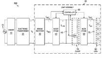
- FIG. 5illustrates an example lighting system 500 including a controller 60 integral to a lamp assembly 90 for providing compatibility between a low-power light source (e.g., LEDs 80 ) and other elements of lighting system 500 , in accordance with embodiments of the present disclosure.
- lightning system 500may include a voltage supply 5 , a leading-edge dimmer 10 , an electronic transformer 20 , and a lamp assembly 90 .
- Voltage supply 5may generate a supply voltage that is, for example, a nominally 60 Hz/110 V line voltage in the United States of America or a nominally 50 Hz/220 V line voltage in Europe.
- Leading-edge dimmer 10may comprise any system, device, or apparatus for generating a dimming signal to other elements of lighting system 500 , the dimming signal representing a dimming level that causes lighting system 500 to adjust power delivered to lamp assembly 90 , and, thus, depending on the dimming level, increase or decrease the brightness of LEDs 80 or another light source integral to lamp assembly 90 .
- leading-edge dimmer 10may include a leading-edge dimmer similar or identical to that depicted in FIGS. 1 and 3 .
- Electronic transformer 20may comprise any system, device, or apparatus for transferring energy by inductive coupling between winding circuits of transformer 20 .
- electronic transformer 20may include a magnetic transformer similar or identical to that depicted in FIG. 3 , or any other suitable transformer.
- Lamp assembly 90may comprise any system, device, or apparatus for converting electrical energy (e.g., delivered by electronic transformer 20 ) into photonic energy (e.g., at LEDs 80 ).
- lamp assembly 90may comprise a multifaceted reflector form factor (e.g., an MR16 form factor).
- lamp assembly 90may comprise an LED lamp.
- lamp assembly 90may include a bridge rectifier 30 , a boost converter stage 40 , a link capacitor 45 , a buck converter stage 50 , a load capacitor 75 , a power-dissipating clamp 70 , LEDs 80 , and a controller 60 .
- Bridge rectifier 30may comprise any suitable electrical or electronic device as is known in the art for converting the whole of alternating current voltage signal v s into a rectified voltage signal v REC having only one polarity.
- Boost converter stage 40may comprise any system, device, or apparatus configured to convert an input voltage (e.g., v REC ) to a higher output voltage (e.g., v LINK ) wherein the conversion is based on a control signal (e.g., a control signal communicated from controller 60 , as explained in greater detail below).
- buck converter stage 50may comprise any system, device, or apparatus configured to convert an input voltage (e.g., v LINK ) to a lower output voltage (e.g., v OUT ) wherein the conversion is based on another control signal (e.g., another control signal communicated from controller 60 , as explained in greater detail below).
- Each of link capacitor 45 and output capacitor 75may comprise any system, device, or apparatus store energy in an electric field.
- Link capacitor 45may be configured such that it stores energy generated by boost converter stage 40 in the form of the voltage v LINK .
- Output capacitor 75may be configured such that it stores energy generated by buck converter stage 50 in the form of the voltage v OUT .
- Power-dissipating clamp 70may comprise any system, device, or apparatus configured to, when selectively activated, dissipate energy stored on link capacitor 45 , thus decreasing voltage v LINK .
- clamp 70may comprise a resistor in series with a switch (e.g., a transistor), such that clamp 70 may be selectively enabled and disabled based on a control signal communicated from controller 60 for controlling the switch.
- LEDs 80may comprise one or more light-emitting diodes configured to emit photonic energy in an amount based on the voltage V OUT across the LEDs 80 .
- Controller 60may comprise any system, device, or apparatus configured to, as described in greater detail elsewhere in this disclosure, determine a voltage v REC present at the input of boost converter stage 40 and control an amount of current i REC drawn by the boost converter stage and/or control an amount of current i OUT delivered by buck stage 50 based on such voltage v REC .
- controller 60may be configured to, described in greater detail elsewhere in this disclosure, determine a voltage v LINK present at the output of boost converter stage 40 and control an amount of current i OUT delivered by buck stage 50 and/or selectively enable and disable clamp 70 based on such voltage v LINK .
- controller 60may cause current i REC to decrease, and as voltage v REC decreases, controller 60 may cause current i REC to increase.
- controller 60may cause buck converter stage 50 to output a constant current in an amount necessary to regulate voltage v LINK at a voltage level well above the maximum output voltage v s of electronic transformer 20 , as described in greater detail elsewhere in this disclosure.
- controller 60may sense voltage v LINK and control the current i OUT generated by buck converter stage 50 based on the sensed voltage v LINK . For example, if voltage v LINK falls below a first undervoltage threshold, such event may indicate that buck converter stage 50 is drawing more power than boost converter stage 40 can supply. In response, controller 60 may cause buck converter 50 to decrease the current i OUT until voltage v LINK is no longer below the first undervoltage threshold. In some embodiments, controller 60 may implement a low-pass filter via which current i OUT is decreased, in order to prevent oscillation or hard steps in the visible light output of LEDs 80 .
- the bandwidth of the low-pass filter implemented by controller 60may be increased for as long as voltage v LINK remains below the second undervoltage threshold, in order to prevent voltage v LINK from collapsing to the point in which it can no longer be regulated.
- controller 60may cause buck converter 50 to increase the current i OUT until voltage v LINK is no longer above the maximum threshold voltage.
- controller 60may implement a low-pass filter via which current i OUT is increased, in order to prevent oscillation or hard steps in the visible light output of LEDs 80 .
- controller 60may activate power-dissipating clamp 70 to reduce voltage v LINK .
- controller 60in concert with boost converter stage 40 , buck converter stage 50 , and clamp 70 , may provide an input current waveform i REC which increases as voltage v REC decreases and decreases as voltage v REC increases, and provides hysteretic power regulation of the output of boost converter stage 40 .
- controller 60may meet the requirement of increasing current i REC with decreasing voltage v REC and decreasing current i REC with increasing voltage v REC by producing a substantially constant power across the AC waveform of v REC .
- an electronic transformeris designed to operate on a principle of self-oscillation, wherein current feedback from its output current is used to force oscillation of the electronic transformer. If the load current is below the current necessary to activate transistor base currents (e.g., in transistor 129 depicted in FIG. 3 ) in the positive feedback loop of the electronic transformer, oscillation may fail to sustain itself, and the output voltage and output current of the electronic transformer will fall to zero.
- transistor base currentse.g., in transistor 129 depicted in FIG. 3
- boost converter stage 40is generating a substantially constant power proportional to the dimmer output
- the current drawn from electronic transformer 20is a minimum when the voltage v REC (and thus voltage v s ) is at its maximum magnitude.
- such minimum currentmay fall below the current necessary to sustain oscillation in the electronic transformer. This failure to maintain oscillation results in a lack of energy available from the transformer and ultimately results in an output at LEDs 80 below the desired value.
- controller 60may also implement a servo loop to control the power value used to calculate current i REC based on voltage v REC .
- controller 60may set a to its maximum value (e.g., 2).
- controller 60may include a microprocessor, microcontroller, digital signal processor (DSP), application specific integrated circuit (ASIC), or any other digital or analog circuitry configured to interpret and/or execute program instructions and/or process data.
- controller 60may interpret and/or execute program instructions and/or process data stored in a memory (not explicitly shown) communicatively coupled to controller 60 .
- FIG. 6illustrates a flow chart of an example method 600 for ensuring compatibility between a lamp and an electronic transformer driven by a leading-edge dimmer, in accordance with embodiments of the present disclosure.
- method 600may begin at step 601 .
- teachings of the present disclosuremay be implemented in a variety of configurations of lighting system 500 . As such, the preferred initialization point for method 600 and the order of the steps comprising method 600 may depend on the implementation chosen.
- controller 60may set variable a to its maximum value (e.g., 2).
- controller 60may determine if energy is available to first power converter stage 40 from electronic transformer 20 . If energy is available to first power converter stage 40 from electronic transformer 20 , method 600 may proceed to step 604 . Otherwise, method 600 may proceed to step 606 .
- controller 60may cause buck converter stage 50 to generate a current i OUT .
- controller 60may cause buck converter stage 50 to generate a predetermined initial value of current i OUT (e.g., a percentage of the maximum current i OUT which may be generated by buck converter stage 50 ). Afterwards, current i OUT may change as set forth elsewhere in the description of method 600 .
- controller 60may determine if voltage v LINK is less than a first undervoltage threshold. If voltage v LINK is less than the first undervoltage threshold, method 600 may proceed to step 610 . Otherwise, method 600 may proceed to step 622 .
- controller 60may determine if voltage v LINK is less than a second undervoltage threshold lower than the first undervoltage threshold. If voltage v LINK is less than the second undervoltage threshold, method 600 may proceed to step 612 . Otherwise, method 600 may proceed to step 614 .
- controller 60may select a higher-bandwidth low-pass filter via which current i OUT may be decreased, as described in greater detail below.
- controller 60may select a lower-bandwidth low-pass filter in which current i OUT may be decreased, as described in greater detail below, wherein the lower-bandwidth low-pass filter has a bandwidth lesser than that of the higher-bandwidth low-pass filter.
- controller 60may cause buck converter stage 50 to decrease current i OUT delivered to LEDs 80 .
- Controller 60may implement a low-pass filter (e.g., selected in either of steps 612 or 614 ) in which it causes buck converter stage 50 to decrease current i OUT .
- method 600may proceed again to step 602 .
- controller 60may increase the variable a. After completion of step 620 , method 600 may proceed again to step 602 .
- controller 60may determine if voltage v LINK is greater than a maximum threshold voltage. If voltage v LINK is greater than a maximum threshold voltage, method 600 may proceed to step 624 . Otherwise, method 600 may proceed again to step 602 .
- controller 60may activate clamp 70 in order to reduce voltage v LINK .
- controller 60may determine if current i OUT is at its maximum value (e.g., buck converter 50 producing maximum power in accordance with the power rating of LEDs 80 ). If current i OUT is at its maximum value, method 600 may proceed to step 628 . Otherwise, method 600 may proceed to step 630 .
- current i OUTis at its maximum value
- controller 60may decrease the variable a. After completion of step 618 , method 600 may proceed again to step 602 .
- controller 60may cause buck converter 50 to increase current i OUT .
- Controller 60may implement a low-pass filter in which it causes buck converter stage 50 to increase i OUT .
- method 600may proceed again to step 602 .
- FIG. 6discloses a particular number of steps to be taken with respect to method 600
- method 600may be executed with greater or fewer steps than those depicted in FIG. 6 .
- FIG. 6discloses a certain order of steps to be taken with respect to method 600
- the steps comprising method 600may be completed in any suitable order.
- Method 600may be implemented using controller 60 or any other system operable to implement method 600 .
- method 600may be implemented partially or fully in software and/or firmware embodied in computer-readable media.
- controller 60causes lamp assembly 90 to, draw a first amount of power from the electronic transformer, the first amount of power comprising a maximum amount of a requested amount of power available from the electronic transformer, thus transferring energy from the electronic transformer to an energy storage device (e.g., link capacitor 45 ) in accordance with the first amount of power, wherein the first amount of power equals the product of voltage v REC and the current i REC .
- an energy storage devicee.g., link capacitor 45
- controller 60causes lamp assembly 90 to transfer energy from the energy storage device (e.g., link capacitor 45 ) to a load (e.g., LEDs 80 ) at a rate (e.g., current i OUT ) such that a voltage (e.g., v LINK ) of the energy storage device is regulated within a predetermined voltage range (e.g., above the undervoltage thresholds and below the maximum threshold voltage).
- controller 60may cause lamp assembly 90 to decrease the requested amount of power (e.g., decrease a).
- references in the appended claims to an apparatus or system or a component of an apparatus or system being adapted to, arranged to, capable of, configured to, enabled to, operable to, or operative to perform a particular functionencompasses that apparatus, system, or component, whether or not it or that particular function is activated, turned on, or unlocked, as long as that apparatus, system, or component is so adapted, arranged, capable, configured, enabled, operable, or operative.
Landscapes
- Engineering & Computer Science (AREA)
- Power Engineering (AREA)
- General Engineering & Computer Science (AREA)
- Circuit Arrangement For Electric Light Sources In General (AREA)
- Dc-Dc Converters (AREA)
Abstract
Description
- The present disclosure claims priority to United States Provisional Patent Application Ser. No. 61/736,942, filed Dec. 13, 2012, which is incorporated by reference herein in its entirety.
- The present disclosure also claims priority to U.S. Provisional Patent Application Ser. No. 61/756,744, filed Jan. 25, 2013, which is incorporated by reference herein in its entirety.
- The present disclosure relates in general to the field of electronics, and more specifically to systems and methods for ensuring compatibility between one or more low-power lamps and the power infrastructure to which they are coupled.
- Many electronic systems include circuits, such as switching power converters or transformers that interface with a dimmer. The interfacing circuits deliver power to a load in accordance with the dimming level set by the dimmer. For example, in a lighting system, dimmers provide an input signal to a lighting system. The input signal represents a dimming level that causes the lighting system to adjust power delivered to a lamp, and, thus, depending on the dimming level, increase or decrease the brightness of the lamp. Many different types of dimmers exist. In general, dimmers generate an output signal in which a portion of an alternating current (“AC”) input signal is removed or zeroed out. For example, some analog-based dimmers utilize a triode for alternating current (“triac”) device to modulate a phase angle of each cycle of an alternating current supply voltage. This modulation of the phase angle of the supply voltage is also commonly referred to as “phase cutting” the supply voltage. Phase cutting the supply voltage reduces the average power supplied to a load, such as a lighting system, and thereby controls the energy provided to the load.
- A particular type of a triac-based, phase-cutting dimmer is known as a leading-edge dimmer. A leading-edge dimmer phase cuts from the beginning of an AC cycle, such that during the phase-cut angle, the dimmer is “off” and supplies no output voltage to its load, and then turns “on” after the phase-cut angle and passes phase-cut input signal to its load. To ensure proper operation, the load must provide to the leading-edge dimmer a load current sufficient to maintain an inrush current above a current necessary for maintaining conduction by the triac. Due to the sudden increase in voltage provided by the dimmer and the presence of capacitors in the dimmer, the current that must be provided is typically substantially higher than the steady state current necessary for triac conduction.
FIG. 1 depicts alighting system 100 that includes a triac-based leading-edge dimmer 102 and alamp 142.FIG. 2 depicts example voltage and current graphs associated withlighting system 100. Referring toFIGS. 1 and 2 ,lighting system 100 receives an AC supply voltage VSUPPLYfromvoltage supply 104. The supply voltage VSUPPLYis, for example, a nominally 60 Hz/110 V line voltage in the United States of America or a nominally 50 Hz/220 V line voltage in Europe. Triac106 acts as a voltage-driven switch, and agate terminal 108 oftriac 106 controls current flow between thefirst terminal 110 and thesecond terminal 112. A gate voltage VGon thegate terminal 108 above a firing threshold voltage value VFwill causetriac 106 to turn ON, in turn causing a short ofcapacitor 121 and allowing current to flow throughtriac 106 and dimmer102 to generate an output current iDIM.- Assuming a resistive load for
lamp 142, the dimmer output voltage VΦ— DIMis zero volts from the beginning of each ofhalf cycles — DIMrepresents the output voltage ofdimmer 102. During timer period tOFF, the dimmer102 chops or cuts the supply voltage VSUPPLYso that the dimmer output voltage VΦ— DIMremains at zero volts during time period tOFF. At time t1, the gate voltage VGreaches the firing threshold value VF, andtriac 106 begins conducting. Oncetriac 106 turns ON, the dimmer voltage VΦ— DIMtracks the supply voltage VSUPPLYduring time period tON. - Once
triac 106 turns ON, the current iDIMdrawn fromtriac 106 must exceed an attach current iATTin order to sustain the inrush current throughtriac 106 above a threshold current necessary for openingtriac 106. In addition, oncetriac 106 turns ON,triac 106 continues to conduct current iDIMregardless of the value of the gate voltage VGas long as the current iDIMremains above a holding current value iHC. The attach current value iATTand the holding current value iHCare a function of the physical characteristics of thetriac 106. Once the current iDIMdrops below the holding current value iHC, i.e. iDIM<iHC,triac 106 turns OFF (i.e., stops conducting), until the gate voltage VGagain reaches the firing threshold value VF. In many traditional applications, the holding current value iHCis generally low enough so that, ideally, the current iDIMdrops below the holding current value iHCwhen the supply voltage VSUPPLYis approximately zero volts near the end of thehalf cycle 202 at time t2. - The
variable resistor 114 in series with the parallel connectedresistor 116 andcapacitor 118 form atiming circuit 115 to control the time t1at which the gate voltage VGreaches the firing threshold value VF. Increasing the resistance ofvariable resistor 114 increases the time tOFF, and decreasing the resistance ofvariable resistor 114 decreases the time tOFF. The resistance value of thevariable resistor 114 effectively sets a dimming value forlamp 142. Diac119 provides current flow into thegate terminal 108 oftriac 106. Thedimmer 102 also includes aninductor choke 120 to smooth the dimmer output voltage VΦ— DIM. Triac-baseddimmer 102 also includes acapacitor 121 connected acrosstriac 106 andinductor choke 120 to reduce electro-magnetic interference. - Ideally, modulating the phase angle of the dimmer output voltage VΦ
— DIMeffectively turns thelamp 142 OFF during time period tOFFand ON during time period tONfor each half cycle of the supply voltage VSUPPLY. Thus, ideally, thedimmer 102 effectively controls the average energy supplied tolamp 142 in accordance with the dimmer output voltage VΦ— DIM. - The triac-based dimmer102 adequately functions in many circumstances, such as when
lamp 142 consumes a relatively high amount of power, such as an incandescent light bulb. However, in circumstances in whichdimmer 102 is loaded with a lower-power load (e.g., a light-emitting diode or LED lamp), such load may draw a small amount of current iDIM, and it is possible that the current iDIMmay fail to reach the attach current iATTand also possible that current iDIMmay prematurely drop below the holding current value iHCbefore the supply voltage VSUPPLYreaches approximately zero volts. If the current iDIMfails to reach the attach current iATT,dimmer 102 may prematurely disconnect and may not pass the appropriate portion of input voltage VSUPPLYto its output. If the current iDIMprematurely drops below the holding current value iHC, thedimmer 102 prematurely shuts down, and the dimmer voltage VΦ— DIMwill prematurely drop to zero. When the dimmer voltage VΦ— DIMprematurely drops to zero, the dimmer voltage VΦ— DIMdoes not reflect the intended dimming value as set by the resistance value ofvariable resistor 114. For example, when the current iDIMdrops below the holding current value iHCat a time significantly earlier than t2for thedimmer voltage V Φ— DIM206, the ON time period tONprematurely ends at a time earlier than t2instead of ending at time t2, thereby decreasing the amount of energy delivered to the load. Thus, the energy delivered to the load will not match the dimming level corresponding to the dimmer voltage VΦ— DIM. In addition, when VΦ— DIMprematurely drops to zero, charge may accumulate oncapacitor 118 andgate 108, causingtriac 106 to again refire if gate voltage VGexceeds firing threshold voltage VFduring thesame half cycle triac 106 to fire incorrectly in subsequent half cycles due to such accumulated charge. Thus, premature disconnection oftriac 106 may lead to errors in the timing circuitry ofdimmer 102 and instability in its operation. - Dimming a light source with dimmers saves energy when operating a light source and also allows a user to adjust the intensity of the light source to a desired level. However, conventional dimmers, such as a triac-based leading-edge dimmer, that are designed for use with resistive loads, such as incandescent light bulbs, often do not perform well when attempting to supply a raw, phase modulated signal to a reactive load such as an electronic power converter or transformer.
- Transformers present in a power infrastructure may include magnetic or electronic transformers. A magnetic transformer typically comprises two coils of conductive material (e.g., copper) each wrapped around a core of material having a high magnetic permeability (e.g., iron) such that magnetic flux passes through both coils. In operation, an electric current in the first coil may produce a changing magnetic field in the core, such that the changing magnetic field induces a voltage across the ends of the secondary winding via electromagnetic induction. Thus, a magnetic transformer may step voltage levels up or down while providing electrical isolation in a circuit between components coupled to the primary winding and components coupled to the secondary winding.
- On the other hand, an electronic transformer is a device which behaves in the same manner as a conventional magnetic transformer in that it steps voltage levels up or down while providing isolation and can accommodate load current of any power factor. An electronic transformer generally includes power switches which convert a low-frequency (e.g., direct current to 400 Hertz) voltage wave to a high-frequency voltage wave (e.g., in the order of 10,000 Hertz). A comparatively small magnetic transformer may be coupled to such power switches and thus provides the voltage level transformation and isolation functions of the conventional magnetic transformer.
FIG. 3 depicts alighting system 101 that includes a triac-based leading-edge dimmer102 (e.g., such as that shown inFIG. 1 ), anelectronic transformer 122, and alamp 142. Such asystem 101 may be used, for example, to transform a high voltage (e.g., 110V, 220 V) to a low voltage (e.g., 12 V) for use with a halogen lamp (e.g., an MR16 halogen lamp).FIG. 4 depicts example voltage and current graphs associated withlighting system 101.- As is known in the art, electronic transformers operate on a principle of self-resonant circuitry. Referring to
FIGS. 3 and 4 , whendimmer 102 is used in connection withtransformer 122 and a low-power lamp 142, the low current draw oflamp 142 may be insufficient to allowelectronic transformer 122 to reliably self-oscillate. - To further illustrate,
electronic transformer 122 may receive the dimmer output voltage VΦ— DIMat its input where it is rectified by a full-bridge rectifier formed bydiodes 124. As voltage VΦ— DIMincreases in magnitude at the dimmer firing point t1, voltage oncapacitor 126 may increase to a point wherediac 128 will turn on, thus also turning ontransistor 129. Oncetransistor 129 is on,capacitor 126 may be discharged and oscillation will start due to the self-resonance of switchingtransformer 130, which includes a primary winding (T2a) and two secondary windings (T2band T2c). Accordingly, as depicted inFIG. 4 , an oscillatingoutput voltage V s402 will be formed on the secondary oftransformer 132 and delivered tolamp 142 while dimmer102 is on, bounded by an AC voltage level proportional to VΦ— DIM. - However, as mentioned above, many electronic transformers will not function properly with low-current loads. With a light load, there may be insufficient current through the primary winding of switching
transformer 130 to sustain oscillation. For legacy applications, such as wherelamp 142 is a 35-watt halogen bulb,lamp 142 may draw sufficient current to allowtransformer 122 to sustain oscillation. However, should a lower-power lamp be used, such as a six-watt LED bulb, the current drawn bylamp 142 may be insufficient to sustain oscillation intransformer 122, which may lead to unreliable effects, such as visible flicker and a reduction in total light output below the level indicated by the dimmer. - In addition, traditional approaches do not effectively detect or sense a type of transformer to which a lamp is coupled, further rendering it difficult to ensure compatibility between low-power (e.g., less than twelve watts) lamps and the power infrastructure to which they are applied.
- In accordance with the teachings of the present disclosure, certain disadvantages and problems associated with ensuring compatibility of a low-power lamp with a dimmer and a transformer may be reduced or eliminated.
- In accordance with embodiments of the present disclosure, an apparatus may include a controller to provide compatibility between a load and a secondary winding of an electronic transformer driven by a leading-edge dimmer. The controller may be configured to, responsive to determining that energy is available from the electronic transformer, draw a requested amount of power from the electronic transformer thus transferring energy from the electronic transformer to an energy storage device in accordance with the requested amount of power. The controller may also be configured to transfer energy from the energy storage device to the load at a rate such that a voltage of the energy storage device is regulated within a predetermined voltage range.
- In accordance with these and other embodiments of the present disclosure, a method to provide compatibility between a load and a secondary winding of the electronic transformer driven by a leading-edge dimmer may include, responsive to determining that energy is available from the electronic transformer, drawing a requested amount of power from the electronic transformer thus transferring energy from the electronic transformer to an energy storage device in accordance with the requested amount of power. The method may further include transferring energy from the energy storage device to the load at a rate such that a voltage of the energy storage device is regulated within a predetermined voltage range.
- In accordance with these and other embodiments of the present disclosure, an apparatus may include a power converter and a controller. The controller may be configured to monitor a voltage at an input of the power converter, cause the power controller to transfer energy from the input to a load at a target current, decrease the target current responsive to determining that the voltage is less than or equal to an undervoltage threshold, and increase the target current responsive to determining that the voltage is greater than or equal to a maximum threshold voltage.
- In accordance with these and other embodiments of the present disclosure, a method may include monitoring a voltage at an input of a power converter. The method may also include causing the power controller to transfer energy from the input to a load at a target current. The method may additionally include decreasing the target current responsive to determining that the voltage is less than or equal to an undervoltage threshold. The method may further include increasing the target current responsive to determining that the voltage is greater than or equal to a maximum threshold voltage. Technical advantages of the present disclosure may be readily apparent to one of ordinary skill in the art from the figures, description and claims included herein. The objects and advantages of the embodiments will be realized and achieved at least by the elements, features, and combinations particularly pointed out in the claims.
- It is to be understood that both the foregoing general description and the following detailed description are examples and explanatory and are not restrictive of the claims set forth in this disclosure.
- A more complete understanding of the present embodiments and advantages thereof may be acquired by referring to the following description taken in conjunction with the accompanying drawings, in which like reference numbers indicate like features, and wherein:
FIG. 1 illustrates a lighting system that includes a triac-based leading-edge dimmer, as is known in the art;FIG. 2 illustrates example voltage and current graphs associated with the lighting system depicted inFIG. 1 , as is known in the art;FIG. 3 illustrates a lighting system that includes a triac-based leading-edge dimmer and an electronic transformer, as is known in the art;FIG. 4 illustrates example voltage and current graphs associated with the lighting system depicted inFIG. 3 , as is known in the art;FIG. 5 illustrates an example lighting system including a controller for providing compatibility between a low-power lamp and other elements of a lighting system, in accordance with embodiments of the present disclosure; andFIG. 6 illustrates a flow chart of an example method for ensuring compatibility between a lamp and an electronic transformer driver by a leading-edge dimmer, in accordance with embodiments of the present disclosure.FIG. 5 illustrates anexample lighting system 500 including acontroller 60 integral to alamp assembly 90 for providing compatibility between a low-power light source (e.g., LEDs80) and other elements oflighting system 500, in accordance with embodiments of the present disclosure. As shown inFIG. 5 ,lightning system 500 may include avoltage supply 5, a leading-edge dimmer 10, anelectronic transformer 20, and alamp assembly 90.Voltage supply 5 may generate a supply voltage that is, for example, a nominally 60 Hz/110 V line voltage in the United States of America or a nominally 50 Hz/220 V line voltage in Europe.- Leading-
edge dimmer 10 may comprise any system, device, or apparatus for generating a dimming signal to other elements oflighting system 500, the dimming signal representing a dimming level that causeslighting system 500 to adjust power delivered tolamp assembly 90, and, thus, depending on the dimming level, increase or decrease the brightness ofLEDs 80 or another light source integral tolamp assembly 90. Thus, leading-edge dimmer 10 may include a leading-edge dimmer similar or identical to that depicted inFIGS. 1 and 3 . Electronic transformer 20 may comprise any system, device, or apparatus for transferring energy by inductive coupling between winding circuits oftransformer 20. Thus,electronic transformer 20 may include a magnetic transformer similar or identical to that depicted inFIG. 3 , or any other suitable transformer.Lamp assembly 90 may comprise any system, device, or apparatus for converting electrical energy (e.g., delivered by electronic transformer20) into photonic energy (e.g., at LEDs80). In some embodiments,lamp assembly 90 may comprise a multifaceted reflector form factor (e.g., an MR16 form factor). In these and other embodiments,lamp assembly 90 may comprise an LED lamp. As shown inFIG. 5 ,lamp assembly 90 may include abridge rectifier 30, aboost converter stage 40, alink capacitor 45, abuck converter stage 50, aload capacitor 75, a power-dissipatingclamp 70,LEDs 80, and acontroller 60.Bridge rectifier 30 may comprise any suitable electrical or electronic device as is known in the art for converting the whole of alternating current voltage signal vsinto a rectified voltage signal vREChaving only one polarity.Boost converter stage 40 may comprise any system, device, or apparatus configured to convert an input voltage (e.g., vREC) to a higher output voltage (e.g., vLINK) wherein the conversion is based on a control signal (e.g., a control signal communicated fromcontroller 60, as explained in greater detail below). Similarly,buck converter stage 50 may comprise any system, device, or apparatus configured to convert an input voltage (e.g., vLINK) to a lower output voltage (e.g., vOUT) wherein the conversion is based on another control signal (e.g., another control signal communicated fromcontroller 60, as explained in greater detail below).- Each of
link capacitor 45 andoutput capacitor 75 may comprise any system, device, or apparatus store energy in an electric field.Link capacitor 45 may be configured such that it stores energy generated byboost converter stage 40 in the form of the voltage vLINK. Output capacitor75 may be configured such that it stores energy generated bybuck converter stage 50 in the form of the voltage vOUT. - Power-dissipating
clamp 70 may comprise any system, device, or apparatus configured to, when selectively activated, dissipate energy stored onlink capacitor 45, thus decreasing voltage vLINK. In embodiments represented byFIG. 5 , clamp70 may comprise a resistor in series with a switch (e.g., a transistor), such thatclamp 70 may be selectively enabled and disabled based on a control signal communicated fromcontroller 60 for controlling the switch. LEDs 80 may comprise one or more light-emitting diodes configured to emit photonic energy in an amount based on the voltage VOUTacross theLEDs 80.Controller 60 may comprise any system, device, or apparatus configured to, as described in greater detail elsewhere in this disclosure, determine a voltage vRECpresent at the input ofboost converter stage 40 and control an amount of current iRECdrawn by the boost converter stage and/or control an amount of current iOUTdelivered bybuck stage 50 based on such voltage vREC. In addition or alternatively,controller 60 may be configured to, described in greater detail elsewhere in this disclosure, determine a voltage vLINKpresent at the output ofboost converter stage 40 and control an amount of current iOUTdelivered bybuck stage 50 and/or selectively enable and disableclamp 70 based on such voltage vLINK.- In operation,
controller 60 may, when power is available fromelectronic transformer 20 and based on a measured voltage vREC, generate current iRECinversely proportional to vREC(e.g., iREC=P/vREC, where P is a predetermined power, as described elsewhere in this disclosure). Thus, as voltage vRECincreases,controller 60 may cause current iRECto decrease, and as voltage vRECdecreases,controller 60 may cause current iRECto increase. In addition,controller 60 may causebuck converter stage 50 to output a constant current in an amount necessary to regulate voltage vLINKat a voltage level well above the maximum output voltage vsofelectronic transformer 20, as described in greater detail elsewhere in this disclosure. - To regulate voltage vLINK,
controller 60 may sense voltage vLINKand control the current iOUTgenerated bybuck converter stage 50 based on the sensed voltage vLINK. For example, if voltage vLINKfalls below a first undervoltage threshold, such event may indicate thatbuck converter stage 50 is drawing more power thanboost converter stage 40 can supply. In response,controller 60 may causebuck converter 50 to decrease the current iOUTuntil voltage vLINKis no longer below the first undervoltage threshold. In some embodiments,controller 60 may implement a low-pass filter via which current iOUTis decreased, in order to prevent oscillation or hard steps in the visible light output ofLEDs 80. As another example, should voltage vLINKfall below a second undervoltage threshold with a magnitude lower than the first undervoltage threshold, the bandwidth of the low-pass filter implemented bycontroller 60 may be increased for as long as voltage vLINKremains below the second undervoltage threshold, in order to prevent voltage vLINKfrom collapsing to the point in which it can no longer be regulated. - As a further example, if voltage vLINKrises above a maximum threshold voltage, such event may indicate that
boost converter stage 40 is generating more power thanbuck converter stage 50 can consume. In response,controller 60 may causebuck converter 50 to increase the current iOUTuntil voltage vLINKis no longer above the maximum threshold voltage. In some embodiments,controller 60 may implement a low-pass filter via which current iOUTis increased, in order to prevent oscillation or hard steps in the visible light output ofLEDs 80. In addition or alternatively, responsive to voltage vLINKrising above the maximum threshold voltage,controller 60 may activate power-dissipatingclamp 70 to reduce voltage vLINK. - Accordingly,
controller 60, in concert withboost converter stage 40,buck converter stage 50, and clamp70, may provide an input current waveform iRECwhich increases as voltage vRECdecreases and decreases as voltage vRECincreases, and provides hysteretic power regulation of the output ofboost converter stage 40. In some embodiments,controller 60 may meet the requirement of increasing current iRECwith decreasing voltage vRECand decreasing current iRECwith increasing voltage vRECby producing a substantially constant power across the AC waveform of vREC. - As described above, an electronic transformer is designed to operate on a principle of self-oscillation, wherein current feedback from its output current is used to force oscillation of the electronic transformer. If the load current is below the current necessary to activate transistor base currents (e.g., in
transistor 129 depicted inFIG. 3 ) in the positive feedback loop of the electronic transformer, oscillation may fail to sustain itself, and the output voltage and output current of the electronic transformer will fall to zero. - In
lighting system 500, becauseboost converter stage 40 is generating a substantially constant power proportional to the dimmer output, the current drawn fromelectronic transformer 20 is a minimum when the voltage vREC(and thus voltage vs) is at its maximum magnitude. With many electronic transformers, such minimum current may fall below the current necessary to sustain oscillation in the electronic transformer. This failure to maintain oscillation results in a lack of energy available from the transformer and ultimately results in an output atLEDs 80 below the desired value. - Accordingly, in addition to the functionality described above,
controller 60 may also implement a servo loop to control the power value used to calculate current iRECbased on voltage vREC. In accordance with such servo loop,controller 60 may generate current iRECin accordance with the equation iREC=aP/vREC, wherein a is a dimensionless variable multiplier having a value based on at least one of voltage vRECand an output power generated by buck converter stage50 (as described in greater detail below), and P is a rated power ofLEDs 80. At startup ofcontroller 60,controller 60 may set a to its maximum value (e.g., 2). For increasing phase angles of dimmer10, the current drawn byboost converter stage 40 will be at an elevated level (iREC=aP/vREC, where a is at its maximum), until the power output ofbuck converter stage 50 reaches its maximum (e.g., P) and clamp70 remains activated. At this point, because output power ofbuck converter stage 50 is at its maximum, the power generated byboost converter stage 40 may be reduced and still maintain generation of the same existing light output onLEDs 80. Thus, because output power ofbuck converter stage 50 is at its maximum and clamp70 is activated (e.g., voltage vLINKis above the aforementioned maximum threshold voltage),controller 60 may decrease the value of a until either clamp70 is no longer activated (e.g., voltage vLINKis no longer above the aforementioned maximum threshold voltage) or a reaches its minimum level (e.g., a=1, corresponding to power generation ofboost converter stage 40 being equal to rated power of LEDs80). Conversely, when the phase angle of dimmer10 is decreased and voltage vLINKbegins approaching the aforementioned first threshold,controller 60 may increase a. Once a is increased to its maximum value (e.g., a=2),controller 60 may decrease current iOUTbased on voltage vLINK, as described above. - In some embodiments,
controller 60 may include a microprocessor, microcontroller, digital signal processor (DSP), application specific integrated circuit (ASIC), or any other digital or analog circuitry configured to interpret and/or execute program instructions and/or process data. In some embodiments,controller 60 may interpret and/or execute program instructions and/or process data stored in a memory (not explicitly shown) communicatively coupled tocontroller 60. FIG. 6 illustrates a flow chart of anexample method 600 for ensuring compatibility between a lamp and an electronic transformer driven by a leading-edge dimmer, in accordance with embodiments of the present disclosure. According to some embodiments,method 600 may begin atstep 601. As noted above, teachings of the present disclosure may be implemented in a variety of configurations oflighting system 500. As such, the preferred initialization point formethod 600 and the order of thesteps comprising method 600 may depend on the implementation chosen.- At
step 601,controller 60 may set variable a to its maximum value (e.g., 2). - At
step 602,controller 60 may determine if energy is available to firstpower converter stage 40 fromelectronic transformer 20. If energy is available to firstpower converter stage 40 fromelectronic transformer 20,method 600 may proceed to step604. Otherwise,method 600 may proceed to step606. - At
step 604, responsive to a determination that energy is available to firstpower converter stage 40 fromelectronic transformer 20,controller 60 may causeboost converter stage 40 to draw current iRECin accordance with the equation iREC=aP/vREC, wherein a is a dimensionless variable multiplier having a value based on at least one of voltage vRECand an output power generated bybuck converter stage 50, and P is a rated power ofLEDs 80. - At
step 606,controller 60 may causebuck converter stage 50 to generate a current iOUT. During the first execution ofstep 606,controller 60 may causebuck converter stage 50 to generate a predetermined initial value of current iOUT(e.g., a percentage of the maximum current iOUTwhich may be generated by buck converter stage50). Afterwards, current iOUTmay change as set forth elsewhere in the description ofmethod 600. - At
step 608,controller 60 may determine if voltage vLINKis less than a first undervoltage threshold. If voltage vLINKis less than the first undervoltage threshold,method 600 may proceed to step610. Otherwise,method 600 may proceed to step622. - At
step 610, responsive to a determination that voltage vLINKis less than the first undervoltage threshold,controller 60 may determine if voltage vLINKis less than a second undervoltage threshold lower than the first undervoltage threshold. If voltage vLINKis less than the second undervoltage threshold,method 600 may proceed to step612. Otherwise,method 600 may proceed to step614. - At
step 612, responsive to a determination that voltage vLINKis less than the second undervoltage threshold,controller 60 may select a higher-bandwidth low-pass filter via which current iOUTmay be decreased, as described in greater detail below. - At
step 614, responsive to a determination that voltage vLINKis more than the second undervoltage threshold,controller 60 may select a lower-bandwidth low-pass filter in which current iOUTmay be decreased, as described in greater detail below, wherein the lower-bandwidth low-pass filter has a bandwidth lesser than that of the higher-bandwidth low-pass filter. - At
step 616,controller 60 may determine if variable a is at its maximum value (e.g., a=2). If variable a is at its maximum value,method 600 may proceed to step618. Otherwise,method 600 may proceed to step620. - At
step 618, in response to a determination that variable a is at its maximum value,controller 60 may causebuck converter stage 50 to decrease current iOUTdelivered toLEDs 80.Controller 60 may implement a low-pass filter (e.g., selected in either ofsteps 612 or614) in which it causesbuck converter stage 50 to decrease current iOUT. After completion ofstep 618,method 600 may proceed again to step602. - At
step 620, in response to a determination that variable a is less than its maximum value,controller 60 may increase the variable a. After completion ofstep 620,method 600 may proceed again to step602. - At
step 622, responsive to a determination that voltage vLINKis greater than the first undervoltage threshold,controller 60 may determine if voltage vLINKis greater than a maximum threshold voltage. If voltage vLINKis greater than a maximum threshold voltage,method 600 may proceed to step624. Otherwise,method 600 may proceed again to step602. - At step624 responsive to a determination that voltage vLINKis greater than the maximum threshold voltage,
controller 60 may activateclamp 70 in order to reduce voltage vLINK. - At
step 626,controller 60 may determine if current iOUTis at its maximum value (e.g.,buck converter 50 producing maximum power in accordance with the power rating of LEDs80). If current iOUTis at its maximum value,method 600 may proceed to step628. Otherwise,method 600 may proceed to step630. - At
step 628, in response to a determination that current iOUTis at its maximum value,controller 60 may decrease the variable a. After completion ofstep 618,method 600 may proceed again to step602. - At
step 630, in response to a determination that current iOUTis less than its maximum value,controller 60 may causebuck converter 50 to increase current iOUT.Controller 60 may implement a low-pass filter in which it causesbuck converter stage 50 to increase iOUT. After completion ofstep 620,method 600 may proceed again to step602. - Although
FIG. 6 discloses a particular number of steps to be taken with respect tomethod 600,method 600 may be executed with greater or fewer steps than those depicted inFIG. 6 . In addition, althoughFIG. 6 discloses a certain order of steps to be taken with respect tomethod 600, thesteps comprising method 600 may be completed in any suitable order. Method 600 may be implemented usingcontroller 60 or any other system operable to implementmethod 600. In certain embodiments,method 600 may be implemented partially or fully in software and/or firmware embodied in computer-readable media.- Thus, in accordance with the methods and systems disclosed herein,
controller 60causes lamp assembly 90 to, draw a first amount of power from the electronic transformer, the first amount of power comprising a maximum amount of a requested amount of power available from the electronic transformer, thus transferring energy from the electronic transformer to an energy storage device (e.g., link capacitor45) in accordance with the first amount of power, wherein the first amount of power equals the product of voltage vRECand the current iREC. In addition,controller 60causes lamp assembly 90 to transfer energy from the energy storage device (e.g., link capacitor45) to a load (e.g., LEDs80) at a rate (e.g., current iOUT) such that a voltage (e.g., vLINK) of the energy storage device is regulated within a predetermined voltage range (e.g., above the undervoltage thresholds and below the maximum threshold voltage). In addition, responsive to determining that the first amount of power is greater than a maximum amount of power deliverable to the load,controller 60 may causelamp assembly 90 to decrease the requested amount of power (e.g., decrease a). - As used herein, when two or more elements are referred to as “coupled” to one another, such term indicates that such two or more elements are in electronic communication whether connected indirectly or directly, with or without intervening elements.
- This disclosure encompasses all changes, substitutions, variations, alterations, and modifications to the example embodiments herein that a person having ordinary skill in the art would comprehend. Similarly, where appropriate, the appended claims encompass all changes, substitutions, variations, alterations, and modifications to the example embodiments herein that a person having ordinary skill in the art would comprehend. Moreover, reference in the appended claims to an apparatus or system or a component of an apparatus or system being adapted to, arranged to, capable of, configured to, enabled to, operable to, or operative to perform a particular function encompasses that apparatus, system, or component, whether or not it or that particular function is activated, turned on, or unlocked, as long as that apparatus, system, or component is so adapted, arranged, capable, configured, enabled, operable, or operative.
- All examples and conditional language recited herein are intended for pedagogical objects to aid the reader in understanding the disclosure and the concepts contributed by the inventor to furthering the art, and are construed as being without limitation to such specifically recited examples and conditions. Although embodiments of the present disclosure have been described in detail, it should be understood that various changes, substitutions, and alterations could be made hereto without departing from the spirit and scope of the disclosure.
Claims (39)
Priority Applications (5)
| Application Number | Priority Date | Filing Date | Title |
|---|---|---|---|
| US13/903,591US9273858B2 (en) | 2012-12-13 | 2013-05-28 | Systems and methods for low-power lamp compatibility with a leading-edge dimmer and an electronic transformer |
| PCT/US2013/071690WO2014092998A1 (en) | 2012-12-13 | 2013-11-25 | Systems and methods for controlling a power controller |
| CN201380072964.0ACN105027673B (en) | 2012-12-13 | 2013-11-25 | Systems and methods of controlling power controllers |
| JP2015547390AJP6293781B2 (en) | 2012-12-13 | 2013-11-25 | System and method for controlling a power controller |
| EP13803383.2AEP2932796A1 (en) | 2012-12-13 | 2013-11-25 | Systems and methods for controlling a power controller |
Applications Claiming Priority (3)
| Application Number | Priority Date | Filing Date | Title |
|---|---|---|---|
| US201261736942P | 2012-12-13 | 2012-12-13 | |
| US201361756744P | 2013-01-25 | 2013-01-25 | |
| US13/903,591US9273858B2 (en) | 2012-12-13 | 2013-05-28 | Systems and methods for low-power lamp compatibility with a leading-edge dimmer and an electronic transformer |
Publications (2)
| Publication Number | Publication Date |
|---|---|
| US20140167639A1true US20140167639A1 (en) | 2014-06-19 |
| US9273858B2 US9273858B2 (en) | 2016-03-01 |
Family
ID=50930119
Family Applications (2)
| Application Number | Title | Priority Date | Filing Date |
|---|---|---|---|
| US13/903,632Expired - Fee RelatedUS9341358B2 (en) | 2012-12-13 | 2013-05-28 | Systems and methods for controlling a power controller |
| US13/903,591Expired - Fee RelatedUS9273858B2 (en) | 2012-12-13 | 2013-05-28 | Systems and methods for low-power lamp compatibility with a leading-edge dimmer and an electronic transformer |
Family Applications Before (1)
| Application Number | Title | Priority Date | Filing Date |
|---|---|---|---|
| US13/903,632Expired - Fee RelatedUS9341358B2 (en) | 2012-12-13 | 2013-05-28 | Systems and methods for controlling a power controller |
Country Status (5)
| Country | Link |
|---|---|
| US (2) | US9341358B2 (en) |
| EP (1) | EP2932796A1 (en) |
| JP (1) | JP6293781B2 (en) |
| CN (1) | CN105027673B (en) |
| WO (1) | WO2014092998A1 (en) |
Cited By (9)
| Publication number | Priority date | Publication date | Assignee | Title |
|---|---|---|---|---|
| US9072125B2 (en) | 2012-07-03 | 2015-06-30 | Cirrus Logic, Inc. | Systems and methods for determining a type of transformer to which a load is coupled |
| US20150282275A1 (en)* | 2014-03-25 | 2015-10-01 | General Electric Company | Dimmer with photo sensor and high/low clamping |
| US9215770B2 (en) | 2012-07-03 | 2015-12-15 | Philips International, B.V. | Systems and methods for low-power lamp compatibility with a trailing-edge dimmer and an electronic transformer |
| US9215765B1 (en) | 2012-10-26 | 2015-12-15 | Philips International, B.V. | Systems and methods for low-power lamp compatibility with an electronic transformer |
| US9263964B1 (en) | 2013-03-14 | 2016-02-16 | Philips International, B.V. | Systems and methods for low-power lamp compatibility with an electronic transformer |
| US9341358B2 (en) | 2012-12-13 | 2016-05-17 | Koninklijke Philips N.V. | Systems and methods for controlling a power controller |
| US9385598B2 (en) | 2014-06-12 | 2016-07-05 | Koninklijke Philips N.V. | Boost converter stage switch controller |
| US9385621B2 (en) | 2013-05-13 | 2016-07-05 | Koninklijke Philips N.V. | Stabilization circuit for low-voltage lighting |
| US9635723B2 (en) | 2013-08-30 | 2017-04-25 | Philips Lighting Holding B.V. | Systems and methods for low-power lamp compatibility with a trailing-edge dimmer and an electronic transformer |
Families Citing this family (5)
| Publication number | Priority date | Publication date | Assignee | Title |
|---|---|---|---|---|
| US9030115B2 (en)* | 2012-06-22 | 2015-05-12 | Abl Ip Holding Llc | LED driver with diac-based switch control and dimmable LED driver |
| AT514357B1 (en)* | 2013-05-23 | 2015-03-15 | Fronius Int Gmbh | A method of controlling a battery powered welder |
| CN104066247B (en)* | 2014-06-24 | 2017-02-01 | 浙江生辉照明有限公司 | Drive circuit and dimming control method for LED lighting device |
| US9729077B2 (en)* | 2015-01-16 | 2017-08-08 | Graco Minnesota Inc. | Front end protection power controller |
| JP6562352B2 (en)* | 2015-09-10 | 2019-08-21 | パナソニックIpマネジメント株式会社 | Light control device |
Citations (2)
| Publication number | Priority date | Publication date | Assignee | Title |
|---|---|---|---|---|
| US4008414A (en)* | 1975-07-28 | 1977-02-15 | Power Saver Corporation | Circuit for powering fluorescent lamps |
| US20100164406A1 (en)* | 2008-07-25 | 2010-07-01 | Kost Michael A | Switching power converter control with triac-based leading edge dimmer compatibility |
Family Cites Families (81)
| Publication number | Priority date | Publication date | Assignee | Title |
|---|---|---|---|---|
| US3806829A (en) | 1971-04-13 | 1974-04-23 | Sys Inc | Pulsed laser system having improved energy control with improved power supply laser emission energy sensor and adjustable repetition rate control features |
| US4562382A (en) | 1982-11-26 | 1985-12-31 | Quietlite International Ltd. | Solid-state inverter including a multiple core transformer |
| US5089753A (en) | 1990-07-09 | 1992-02-18 | North American Philips Corporation | Arrangement for predicting failure in fluorescent lamp systems |
| US5040236A (en) | 1990-07-18 | 1991-08-13 | Argus International | Apparatus for irradiation of printed wiring boards and the like |
| US5416387A (en) | 1993-11-24 | 1995-05-16 | California Institute Of Technology | Single stage, high power factor, gas discharge lamp ballast |
| US5583402A (en) | 1994-01-31 | 1996-12-10 | Magnetek, Inc. | Symmetry control circuit and method |
| US5650694A (en) | 1995-03-31 | 1997-07-22 | Philips Electronics North America Corporation | Lamp controller with lamp status detection and safety circuitry |
| US5872429A (en) | 1995-03-31 | 1999-02-16 | Philips Electronics North America Corporation | Coded communication system and method for controlling an electric lamp |
| US6407935B1 (en) | 2000-05-30 | 2002-06-18 | Koninklijke Philips Electronics N.V. | High frequency electronic ballast with reactive power compensation |
| US6369461B1 (en) | 2000-09-01 | 2002-04-09 | Abb Inc. | High efficiency power conditioner employing low voltage DC bus and buck and boost converters |
| IL147578A (en) | 2002-01-10 | 2006-06-11 | Lightech Electronics Ind Ltd | Lamp transformer for use with an electronic dimmer and method for use thereof for reducing acoustic noise |
| TWI222266B (en) | 2002-02-14 | 2004-10-11 | Kazuo Kohno | Self oscillation circuits |
| RU2341840C2 (en) | 2003-05-02 | 2008-12-20 | ЛИМПКИН Джордж Алан | Device for power supply to load and system connected to it |
| US20070149496A1 (en) | 2003-10-31 | 2007-06-28 | Jack Tuszynski | Water-soluble compound |
| US20080119421A1 (en) | 2003-10-31 | 2008-05-22 | Jack Tuszynski | Process for treating a biological organism |
| US20050174162A1 (en) | 2004-02-09 | 2005-08-11 | Taiwan Semiconductor Manufacturing Company | Configurable voltage generator |
| US20050249667A1 (en) | 2004-03-24 | 2005-11-10 | Tuszynski Jack A | Process for treating a biological organism |
| IL163558A0 (en) | 2004-08-16 | 2005-12-18 | Lightech Electronics Ind Ltd | Controllable power supply circuit for an illumination system and methods of operation thereof |
| US7772724B2 (en) | 2005-06-06 | 2010-08-10 | Lutron Electronics Co., Inc. | Load control device for use with lighting circuits having three-way switches |
| US7847440B2 (en) | 2005-06-06 | 2010-12-07 | Lutron Electronics Co., Inc. | Load control device for use with lighting circuits having three-way switches |
| US20070040516A1 (en) | 2005-08-15 | 2007-02-22 | Liang Chen | AC to DC power supply with PFC for lamp |
| US8742674B2 (en) | 2006-01-20 | 2014-06-03 | Point Somee Limited Liability Company | Adaptive current regulation for solid state lighting |
| US8558470B2 (en) | 2006-01-20 | 2013-10-15 | Point Somee Limited Liability Company | Adaptive current regulation for solid state lighting |
| US20080018261A1 (en) | 2006-05-01 | 2008-01-24 | Kastner Mark A | LED power supply with options for dimming |
| US7489120B2 (en) | 2006-07-12 | 2009-02-10 | Power Integrations, Inc. | Method and apparatus for a high voltage power supply circuit |
| GB0617393D0 (en) | 2006-09-04 | 2006-10-11 | Lutron Electronics Co | Variable load circuits for use with lighting control devices |
| US8174204B2 (en)* | 2007-03-12 | 2012-05-08 | Cirrus Logic, Inc. | Lighting system with power factor correction control data determined from a phase modulated signal |
| US20090184652A1 (en) | 2007-04-23 | 2009-07-23 | Lutron Electronics Co., Inc. | Antenna for a Load Control Device Having a Modular Assembly |
| EP2181566A2 (en) | 2007-08-24 | 2010-05-05 | Cirrus Logic, Inc. | Multi-led control |
| JP5199658B2 (en)* | 2007-12-25 | 2013-05-15 | パナソニック株式会社 | Light source lighting device, lighting fixture, lighting system |
| US8115419B2 (en) | 2008-01-23 | 2012-02-14 | Cree, Inc. | Lighting control device for controlling dimming, lighting device including a control device, and method of controlling lighting |
| JP2009195033A (en)* | 2008-02-14 | 2009-08-27 | Toshiba Lighting & Technology Corp | Power supply device and lighting fixture |
| US7812550B2 (en) | 2008-05-28 | 2010-10-12 | Revlite Technologies Inc. | LED replacement for low voltage lamps |
| US7936132B2 (en) | 2008-07-16 | 2011-05-03 | Iwatt Inc. | LED lamp |
| US8067902B2 (en) | 2008-09-05 | 2011-11-29 | Lutron Electronics Co., Inc. | Electronic ballast having a symmetric topology |
| US8288954B2 (en) | 2008-12-07 | 2012-10-16 | Cirrus Logic, Inc. | Primary-side based control of secondary-side current for a transformer |
| US8013544B2 (en) | 2008-12-10 | 2011-09-06 | Linear Technology Corporation | Dimmer control leakage pull down using main power device in flyback converter |
| JP4864994B2 (en) | 2009-03-06 | 2012-02-01 | シャープ株式会社 | LED drive circuit, LED illumination lamp, LED illumination device, and LED illumination system |
| US8222832B2 (en) | 2009-07-14 | 2012-07-17 | Iwatt Inc. | Adaptive dimmer detection and control for LED lamp |
| TW201134305A (en) | 2009-07-27 | 2011-10-01 | Koninkl Philips Electronics Nv | Bleeder circuit |
| US8686668B2 (en) | 2009-10-26 | 2014-04-01 | Koninklijke Philips N.V. | Current offset circuits for phase-cut power control |
| EP2497337B1 (en) | 2009-11-05 | 2020-10-21 | eldoLAB Holding B.V. | Led driver for powering an led unit from a electronic transformer |
| CA2781077A1 (en) | 2009-11-17 | 2012-06-28 | Terralux, Inc. | Led power-supply detection and control |
| US9220133B2 (en) | 2009-11-20 | 2015-12-22 | Lutron Electronics Co., Inc. | Controllable-load circuit for use with a load control device |
| US8664881B2 (en) | 2009-11-25 | 2014-03-04 | Lutron Electronics Co., Inc. | Two-wire dimmer switch for low-power loads |
| US8957662B2 (en) | 2009-11-25 | 2015-02-17 | Lutron Electronics Co., Inc. | Load control device for high-efficiency loads |
| CN102083254B (en)* | 2009-11-30 | 2013-09-18 | 成都芯源系统有限公司 | WLED driving circuit and driving method suitable for triac dimmer |
| DE102010001919B4 (en) | 2010-02-15 | 2012-03-01 | Osram Ag | Circuit and method for controlling a light source |
| CN102792776A (en) | 2010-03-12 | 2012-11-21 | 皇家飞利浦电子股份有限公司 | Power interface for a power supply circuit |
| WO2011141905A1 (en) | 2010-04-29 | 2011-11-17 | Victor Tzinker | Ac-dc converter with unity power factor |
| CN102238774B (en) | 2010-04-30 | 2016-06-01 | 奥斯兰姆有限公司 | Angle of flow acquisition methods and device, and LED driving method and device |
| GB201011081D0 (en) | 2010-07-01 | 2010-08-18 | Macfarlane Alistair | Improved semi resonant switching regulator, power factor control and LED lighting |
| EP2410821B1 (en) | 2010-07-20 | 2014-01-08 | Panasonic Corporation | Lighting device of semiconductor light-emitting element and illumination fixture using the same |
| US8569972B2 (en) | 2010-08-17 | 2013-10-29 | Cirrus Logic, Inc. | Dimmer output emulation |
| CN103155387B (en) | 2010-07-30 | 2016-10-19 | 皇家飞利浦有限公司 | Powering Efficient Lighting Fixtures from Triac-Based Dimmers |
| US9307601B2 (en) | 2010-08-17 | 2016-04-05 | Koninklijke Philips N.V. | Input voltage sensing for a switching power converter and a triac-based dimmer |
| US8847515B2 (en) | 2010-08-24 | 2014-09-30 | Cirrus Logic, Inc. | Multi-mode dimmer interfacing including attach state control |
| US8653759B2 (en) | 2010-10-29 | 2014-02-18 | General Electric Company | Lighting system electronic ballast or driver with shunt control for lighting control quiescent current |
| CN103262399B (en) | 2010-11-04 | 2017-02-15 | 皇家飞利浦有限公司 | Method and device for controlling energy dissipation in switch power converter |
| EP2636139A2 (en) | 2010-11-04 | 2013-09-11 | Cirrus Logic, Inc. | Controlled energy dissipation in a switching power converter |
| WO2012061784A2 (en) | 2010-11-04 | 2012-05-10 | Cirrus Logic, Inc. | Switching power converter input voltage approximate zero crossing determination |
| DE102011055071B4 (en) | 2010-11-08 | 2023-05-04 | Maxim Integrated Products, Inc. | COMPATIBILITY OF ELECTRONIC TRANSFORMERS FOR LED SYSTEMS |
| DK2681969T3 (en) | 2010-11-16 | 2019-03-25 | Signify Holding Bv | REAR EDGE COMPATIBILITY WITH PREVENTION OF HIGH DUMPING RESISTANCE |
| US8432104B2 (en) | 2010-12-09 | 2013-04-30 | Delta Electronics, Inc. | Load current balancing circuit |
| TWI461107B (en) | 2011-03-22 | 2014-11-11 | Richtek Technology Corp | Light emitting device power supply circuit, and light emitting device driver circuit and control method thereof |
| US8933642B2 (en) | 2011-05-13 | 2015-01-13 | General Electric Company | Dimmable LED lamp |
| EP2590477B1 (en) | 2011-11-07 | 2018-04-25 | Silergy Corp. | A method of controlling a ballast, a ballast, a lighting controller, and a digital signal processor |
| US8698483B2 (en) | 2011-11-09 | 2014-04-15 | CRC, Electronics, Inc. | LED lamp driver identification |
| IN2014CN03663A (en) | 2011-11-16 | 2015-10-16 | Koninkl Philips Nv | |
| WO2013090904A1 (en) | 2011-12-16 | 2013-06-20 | Terralux, Inc. | System and methods of applying bleed circuits in led lamps |
| US8928243B2 (en) | 2011-12-27 | 2015-01-06 | Texas Instruments Incorporated | Light driving system and method |
| US9210744B2 (en) | 2012-04-18 | 2015-12-08 | Power Integrations, Inc. | Bleeder circuit for use in a power supply |
| US8933648B1 (en) | 2012-07-03 | 2015-01-13 | Cirrus Logic, Inc. | Systems and methods for selecting a compatibility mode of operation for a lamp assembly |
| US9215770B2 (en) | 2012-07-03 | 2015-12-15 | Philips International, B.V. | Systems and methods for low-power lamp compatibility with a trailing-edge dimmer and an electronic transformer |
| US9072125B2 (en) | 2012-07-03 | 2015-06-30 | Cirrus Logic, Inc. | Systems and methods for determining a type of transformer to which a load is coupled |
| CN102740571B (en)* | 2012-07-18 | 2014-10-15 | 矽力杰半导体技术(杭州)有限公司 | Dimmable LED (Light-Emitting Diode) driving circuit and driving method |
| US9215765B1 (en) | 2012-10-26 | 2015-12-15 | Philips International, B.V. | Systems and methods for low-power lamp compatibility with an electronic transformer |
| US9341358B2 (en) | 2012-12-13 | 2016-05-17 | Koninklijke Philips N.V. | Systems and methods for controlling a power controller |
| EP2997793A1 (en) | 2013-05-13 | 2016-03-23 | Koninklijke Philips N.V. | Stabilization circuit for low-voltage lighting |
| US9635723B2 (en) | 2013-08-30 | 2017-04-25 | Philips Lighting Holding B.V. | Systems and methods for low-power lamp compatibility with a trailing-edge dimmer and an electronic transformer |
| US9385598B2 (en) | 2014-06-12 | 2016-07-05 | Koninklijke Philips N.V. | Boost converter stage switch controller |
- 2013
- 2013-05-28USUS13/903,632patent/US9341358B2/ennot_activeExpired - Fee Related
- 2013-05-28USUS13/903,591patent/US9273858B2/ennot_activeExpired - Fee Related
- 2013-11-25JPJP2015547390Apatent/JP6293781B2/ennot_activeExpired - Fee Related
- 2013-11-25EPEP13803383.2Apatent/EP2932796A1/ennot_activeWithdrawn
- 2013-11-25WOPCT/US2013/071690patent/WO2014092998A1/enactiveApplication Filing
- 2013-11-25CNCN201380072964.0Apatent/CN105027673B/ennot_activeExpired - Fee Related
Patent Citations (2)
| Publication number | Priority date | Publication date | Assignee | Title |
|---|---|---|---|---|
| US4008414A (en)* | 1975-07-28 | 1977-02-15 | Power Saver Corporation | Circuit for powering fluorescent lamps |
| US20100164406A1 (en)* | 2008-07-25 | 2010-07-01 | Kost Michael A | Switching power converter control with triac-based leading edge dimmer compatibility |
Cited By (12)
| Publication number | Priority date | Publication date | Assignee | Title |
|---|---|---|---|---|
| US9072125B2 (en) | 2012-07-03 | 2015-06-30 | Cirrus Logic, Inc. | Systems and methods for determining a type of transformer to which a load is coupled |
| US9167664B2 (en) | 2012-07-03 | 2015-10-20 | Cirrus Logic, Inc. | Systems and methods for low-power lamp compatibility with a trailing-edge dimmer and an electronic transformer |
| US9215770B2 (en) | 2012-07-03 | 2015-12-15 | Philips International, B.V. | Systems and methods for low-power lamp compatibility with a trailing-edge dimmer and an electronic transformer |
| US9655202B2 (en) | 2012-07-03 | 2017-05-16 | Philips Lighting Holding B.V. | Systems and methods for low-power lamp compatibility with a leading-edge dimmer and a magnetic transformer |
| US9215765B1 (en) | 2012-10-26 | 2015-12-15 | Philips International, B.V. | Systems and methods for low-power lamp compatibility with an electronic transformer |
| US9277624B1 (en) | 2012-10-26 | 2016-03-01 | Philips International, B.V. | Systems and methods for low-power lamp compatibility with an electronic transformer |
| US9341358B2 (en) | 2012-12-13 | 2016-05-17 | Koninklijke Philips N.V. | Systems and methods for controlling a power controller |
| US9263964B1 (en) | 2013-03-14 | 2016-02-16 | Philips International, B.V. | Systems and methods for low-power lamp compatibility with an electronic transformer |
| US9385621B2 (en) | 2013-05-13 | 2016-07-05 | Koninklijke Philips N.V. | Stabilization circuit for low-voltage lighting |
| US9635723B2 (en) | 2013-08-30 | 2017-04-25 | Philips Lighting Holding B.V. | Systems and methods for low-power lamp compatibility with a trailing-edge dimmer and an electronic transformer |
| US20150282275A1 (en)* | 2014-03-25 | 2015-10-01 | General Electric Company | Dimmer with photo sensor and high/low clamping |
| US9385598B2 (en) | 2014-06-12 | 2016-07-05 | Koninklijke Philips N.V. | Boost converter stage switch controller |
Also Published As
| Publication number | Publication date |
|---|---|
| US9341358B2 (en) | 2016-05-17 |
| US9273858B2 (en) | 2016-03-01 |
| JP6293781B2 (en) | 2018-03-14 |
| EP2932796A1 (en) | 2015-10-21 |
| CN105027673A (en) | 2015-11-04 |
| CN105027673B (en) | 2017-07-11 |
| WO2014092998A1 (en) | 2014-06-19 |
| JP2015537363A (en) | 2015-12-24 |
| US20140167652A1 (en) | 2014-06-19 |
Similar Documents
| Publication | Publication Date | Title |
|---|---|---|
| US9273858B2 (en) | Systems and methods for low-power lamp compatibility with a leading-edge dimmer and an electronic transformer | |
| US9655202B2 (en) | Systems and methods for low-power lamp compatibility with a leading-edge dimmer and a magnetic transformer | |
| US9215770B2 (en) | Systems and methods for low-power lamp compatibility with a trailing-edge dimmer and an electronic transformer | |
| US8933648B1 (en) | Systems and methods for selecting a compatibility mode of operation for a lamp assembly | |
| US9635723B2 (en) | Systems and methods for low-power lamp compatibility with a trailing-edge dimmer and an electronic transformer | |
| US9101010B2 (en) | High-efficiency lighting devices having dimmer and/or load condition measurement | |
| US8575847B2 (en) | Control circuit of light-emitting element | |
| US9621062B2 (en) | Dimmer output emulation with non-zero glue voltage | |
| CN106664016A (en) | Systems and methods for switching valley switching in power converters | |
| US9867249B2 (en) | Low-cost low-power lighting system and lamp assembly | |
| JP2014517466A (en) | LED retrofit drive circuit and method for operating LED retrofit drive circuit | |
| WO2011159813A1 (en) | Dimmable offline led driver | |
| CN103687167A (en) | lighting device | |
| US20180324917A1 (en) | Systems and methods for maintaining dimmer behavior in a low-power lamp assembly | |
| US9496844B1 (en) | Variable bandwidth filter for dimmer phase angle measurements | |
| WO2014189617A1 (en) | Systems and methods for low-power lamp compatibility with a trailing-edge dimmer and an electronic transformer | |
| CN111246619B (en) | LED driver for phase-cut dimmer |
Legal Events
| Date | Code | Title | Description |
|---|---|---|---|
| AS | Assignment | Owner name:CIRRUS LOGIC, INC., TEXAS Free format text:ASSIGNMENT OF ASSIGNORS INTEREST;ASSIGNORS:KING, ERIC J.;BAKER, DANIEL J.;MELANSON, JOHN L.;SIGNING DATES FROM 20130517 TO 20130604;REEL/FRAME:030897/0631 | |
| ZAAA | Notice of allowance and fees due | Free format text:ORIGINAL CODE: NOA | |
| ZAAB | Notice of allowance mailed | Free format text:ORIGINAL CODE: MN/=. | |
| ZAAA | Notice of allowance and fees due | Free format text:ORIGINAL CODE: NOA | |
| AS | Assignment | Owner name:KONINKLIJKE PHILIPS N.V., NETHERLANDS Free format text:ASSIGNMENT OF ASSIGNORS INTEREST;ASSIGNOR:CIRRUS LOGIC, INC.;REEL/FRAME:037563/0720 Effective date:20150928 | |
| STCF | Information on status: patent grant | Free format text:PATENTED CASE | |
| AS | Assignment | Owner name:PHILIPS LIGHTING HOLDING B.V., NETHERLANDS Free format text:ASSIGNMENT OF ASSIGNORS INTEREST;ASSIGNOR:KONINKLIJKE PHILIPS N.V.;REEL/FRAME:041170/0806 Effective date:20161101 | |
| MAFP | Maintenance fee payment | Free format text:PAYMENT OF MAINTENANCE FEE, 4TH YEAR, LARGE ENTITY (ORIGINAL EVENT CODE: M1551); ENTITY STATUS OF PATENT OWNER: LARGE ENTITY Year of fee payment:4 | |
| AS | Assignment | Owner name:SIGNIFY HOLDING B.V., NETHERLANDS Free format text:CHANGE OF NAME;ASSIGNOR:PHILIPS LIGHTING HOLDING B.V.;REEL/FRAME:050837/0576 Effective date:20190201 | |
| FEPP | Fee payment procedure | Free format text:MAINTENANCE FEE REMINDER MAILED (ORIGINAL EVENT CODE: REM.); ENTITY STATUS OF PATENT OWNER: LARGE ENTITY | |
| LAPS | Lapse for failure to pay maintenance fees | Free format text:PATENT EXPIRED FOR FAILURE TO PAY MAINTENANCE FEES (ORIGINAL EVENT CODE: EXP.); ENTITY STATUS OF PATENT OWNER: LARGE ENTITY | |
| STCH | Information on status: patent discontinuation | Free format text:PATENT EXPIRED DUE TO NONPAYMENT OF MAINTENANCE FEES UNDER 37 CFR 1.362 | |
| FP | Lapsed due to failure to pay maintenance fee | Effective date:20240301 |