US20140135846A1 - Posterior spinal prosthesis - Google Patents
Posterior spinal prosthesisDownload PDFInfo
- Publication number
- US20140135846A1 US20140135846A1US14/157,238US201414157238AUS2014135846A1US 20140135846 A1US20140135846 A1US 20140135846A1US 201414157238 AUS201414157238 AUS 201414157238AUS 2014135846 A1US2014135846 A1US 2014135846A1
- Authority
- US
- United States
- Prior art keywords
- flange
- posterior
- vertebrae
- plate
- spine
- Prior art date
- Legal status (The legal status is an assumption and is not a legal conclusion. Google has not performed a legal analysis and makes no representation as to the accuracy of the status listed.)
- Granted
Links
- 230000001045lordotic effectEffects0.000claimsabstractdescription8
- 239000007943implantSubstances0.000claimsdescription32
- 239000004033plasticSubstances0.000claimsdescription7
- 229920003023plasticPolymers0.000claimsdescription7
- 238000000034methodMethods0.000abstractdescription41
- 230000008569processEffects0.000abstractdescription21
- 230000006837decompressionEffects0.000abstractdescription16
- 210000004872soft tissueAnatomy0.000abstractdescription10
- 210000000278spinal cordAnatomy0.000abstractdescription9
- 210000000115thoracic cavityAnatomy0.000abstractdescription8
- 230000002980postoperative effectEffects0.000abstractdescription7
- 230000006641stabilisationEffects0.000abstractdescription6
- 238000011105stabilizationMethods0.000abstractdescription6
- 210000000577adipose tissueAnatomy0.000abstractdescription3
- 230000000712assemblyEffects0.000description14
- 238000000429assemblyMethods0.000description14
- 210000000988bone and boneAnatomy0.000description14
- 229910052751metalInorganic materials0.000description6
- 239000002184metalSubstances0.000description6
- 210000003484anatomyAnatomy0.000description5
- 230000014759maintenance of locationEffects0.000description5
- 239000004696Poly ether ether ketoneSubstances0.000description4
- RTAQQCXQSZGOHL-UHFFFAOYSA-NTitaniumChemical compound[Ti]RTAQQCXQSZGOHL-UHFFFAOYSA-N0.000description4
- 239000000560biocompatible materialSubstances0.000description4
- 229920002530polyetherether ketonePolymers0.000description4
- 239000010936titaniumSubstances0.000description4
- 229910052719titaniumInorganic materials0.000description4
- 230000008878couplingEffects0.000description3
- 238000010168coupling processMethods0.000description3
- 238000005859coupling reactionMethods0.000description3
- 230000008901benefitEffects0.000description2
- 238000010348incorporationMethods0.000description2
- 239000000463materialSubstances0.000description2
- 238000007747platingMethods0.000description2
- 230000000717retained effectEffects0.000description2
- 238000004513sizingMethods0.000description2
- 208000032170Congenital AbnormalitiesDiseases0.000description1
- 206010061619DeformityDiseases0.000description1
- 208000027418Wounds and injuryDiseases0.000description1
- 230000004308accommodationEffects0.000description1
- 230000006378damageEffects0.000description1
- 201000010099diseaseDiseases0.000description1
- 208000037265diseases, disorders, signs and symptomsDiseases0.000description1
- 238000002513implantationMethods0.000description1
- 208000014674injuryDiseases0.000description1
- 210000004705lumbosacral regionAnatomy0.000description1
- 238000012986modificationMethods0.000description1
- 230000004048modificationEffects0.000description1
- 230000000399orthopedic effectEffects0.000description1
- 238000004321preservationMethods0.000description1
- 230000004044responseEffects0.000description1
Images


Classifications
- A—HUMAN NECESSITIES
- A61—MEDICAL OR VETERINARY SCIENCE; HYGIENE
- A61B—DIAGNOSIS; SURGERY; IDENTIFICATION
- A61B17/00—Surgical instruments, devices or methods
- A61B17/56—Surgical instruments or methods for treatment of bones or joints; Devices specially adapted therefor
- A61B17/58—Surgical instruments or methods for treatment of bones or joints; Devices specially adapted therefor for osteosynthesis, e.g. bone plates, screws or setting implements
- A61B17/68—Internal fixation devices, including fasteners and spinal fixators, even if a part thereof projects from the skin
- A61B17/70—Spinal positioners or stabilisers, e.g. stabilisers comprising fluid filler in an implant
- A61B17/7058—Plates mounted on top of bone anchor heads or shoulders
- A—HUMAN NECESSITIES
- A61—MEDICAL OR VETERINARY SCIENCE; HYGIENE
- A61B—DIAGNOSIS; SURGERY; IDENTIFICATION
- A61B17/00—Surgical instruments, devices or methods
- A61B17/56—Surgical instruments or methods for treatment of bones or joints; Devices specially adapted therefor
- A61B17/58—Surgical instruments or methods for treatment of bones or joints; Devices specially adapted therefor for osteosynthesis, e.g. bone plates, screws or setting implements
- A61B17/68—Internal fixation devices, including fasteners and spinal fixators, even if a part thereof projects from the skin
- A61B17/70—Spinal positioners or stabilisers, e.g. stabilisers comprising fluid filler in an implant
- A61B17/7001—Screws or hooks combined with longitudinal elements which do not contact vertebrae
- A61B17/7032—Screws or hooks with U-shaped head or back through which longitudinal rods pass
Definitions
- the present inventionrelates to spinal devices and, in particular, to spinal prostheses for use with spinal fixation devices, assemblies and systems such as spinal screw and rod assemblies or systems that are attached onto a patient's spine.
- spinal fixation devicestypically include one or more spinal fixation elements, such as relatively rigid fixation rods, that are connected to adjacent vertebrae by attaching the rod to anchor devices, systems and/or assemblies affixed onto the vertebrae.
- the anchor devicesare typically spinal bone screw assemblies that include bone screws and screw head/spinal rod connectors.
- the spinal fixation rodsare typically placed on opposite sides of the spinous processes of adjacent vertebrae in a substantially parallel relationship.
- Spinal fixation rodsmay have pre-determined contours according to properties of the target implantation site. Once installed, the spinal fixation rods hold the vertebrae in a desired spatial relationship. It may also be necessary in some circumstances to provide a spinal cross-connector at one or more points between the two spinal fixation rods in order to provide additional stability to the structure.
- adjacent spinal fixation rod assembliescan be made more robust by using a cross-connector to bridge the pair of spinal rods.
- Current cross-connectorsare generally rods themselves that are adapted for connection at ends thereof to the spinal rods.
- spinal decompression procedureSpinal decompression is achieved in the patient by the removal of several adjacent spinous processes and the elongation and/or stabilization of the adjacent vertebrae through the use of the spinal fixation assemblies such as indicated above (i.e. spinal rods and spinal bone screw/rod holder assemblies).
- spinal fixation assembliessuch as indicated above (i.e. spinal rods and spinal bone screw/rod holder assemblies).
- spinal rods and spinal bone screw/rod holder assembliesi.e. spinal rods and spinal bone screw/rod holder assemblies
- the present inventionis a posterior spinal prosthesis having a body that extends over and covers posterior portions of a spine.
- the posterior spinal prosthesiscan cover exposed portions of the spine especially, but not necessarily, as a result of a medical spine procedure.
- the posterior spinal prosthesismay be used on any portion of the spine such as the cervical vertebrae, the thoracic vertebrae and the lumbar vertebrae.
- the posterior spinal prosthesisis connectable to one or more spine implants or implant constructs (collectively, ‘spine implants’) that have been attached to one or more vertebrae of the spine.
- the spine implantsare situated generally, but not necessarily, on lateral sides of the posterior portion of the vertebrae.
- Such spine implantsinclude, but are not limited to, spine rods, spine rod assemblies/constructs, vertebral bone screws and vertebral bone screw and spine rod holder/connector assemblies/constructs.
- the bodyhas a plate, hood, platform, cover or the like (collectively, ‘plate’) that extends over posterior portions or areas of the vertebrae.
- Fixation elements associated with the bodyallow coupling of the plate to the spine implants.
- the plateis configured so as to project in the posterior direction relative to portions of the fixation elements.
- the fixation elementsare flanges formed on either side of the plate. The flanges are configured to receive a connector that provides coupling of the body to the spine implants, allow for direct connection of the plate to one or more vertebrae or include a connector that provides coupling of the body to the spine implants.
- the fixation elementsmay take other forms as desired.
- the present posterior spinal prosthesisis thus adapted to provide posterior coverage of an exposed spinal cord, soft tissue, Foramen and/or adipose tissue, of one or more vertebrae as a result of the removal the spinous processes and/or the spinous process and laminar hoods from one or more vertebrae of the spine such as for a spinal decompression procedure or other reason.
- the posterior spinal prosthesisalso provides posterior stabilization of the associated vertebrae as well as aiding in preventing post operative soft tissue cavitation at the decompression site.
- the posterior spinal prosthesisis formed of a suitable biocompatible material that is preferably, but not necessarily, a biocompatible plastic such as PEEK (polyetheretherketone). Of course, other biocompatible plastics or materials such as metal may be used.
- the posterior spinal prosthesismay also be formed of a biocompatible plastic with the incorporation of a biocompatible metal such as titanium. Furthermore, the posterior spinal prosthesis may be formed entirely of a biocompatible metal such as titanium.
- the posterior spinal prosthesismay be made in various sizes or sizing platforms in order to accommodate a variety of anatomies. As such, the body may be formed as a single or unitary piece or may be formed as multiple pieces. A multiple piece (i.e. two or more piece) posterior spinal prosthesis may provide accommodation for differing widths between spine implants such as spinal rods for interconnection.
- the body(whether a single or multi-piece body) is characterized by the plate having flanges at lateral sides thereof.
- the lateral sidesare curved, each forming a bend relative to a level defined by the plate, with the flanges disposed at the end of the bends.
- the configuration of the plate, the curved lateral sides and their respective flanges,form a pocket, area, channel or the like.
- the first flangehas an elongated slot extending in the superior/inferior or longitudinal direction with the first slot defining an elongated first outer edge.
- the second flangelikewise has an elongated slot extending in the superior/inferior or longitudinal direction with the second slot defining an elongated second outer edge.
- the plateis at a level relative to a level of the first and second flanges that generally corresponds in height to that of the removed spinous processes such that, when installed, the plate is posterior to the flanges.
- the flangeseach have an undercut or groove on the underside thereof about the respective slots.
- the groovesare sized to provide a trough or channel that receives a connector or spine implant component for mounting the posterior spinal prosthesis.
- the connector or spine implant componenttranslates in the groove to allow variable attachment of the body to the spine implant.
- the body of the posterior spinal prosthesismay moreover be curved from the superior end or side to the inferior end or side. This curvature may be lordotic as in the case of cervical and lumbar posterior spinal prostheses or kyphotic as in the case of thoracic posterior prostheses.
- the present inventionprovides coverage of exposed spinal cord areas, aids in posterior stabilization, and aids in preventing post operative soft tissue cavitation by providing anatomically accurate preservation to the cervical, thoracic and/or lumbar regions of the spine.
- FIG. 1is a perspective view of an exemplary posterior spinal prosthesis fashioned in accordance with the present principles
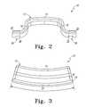
- FIG. 2is a front view of the posterior spinal prosthesis of FIG. 1 taken along line 2 - 2 thereof;
- FIG. 3is a side view of the posterior spinal prosthesis of FIG. 1 taken along line 3 - 3 thereof;
- FIG. 4is a perspective view of a section of the cervical portion of a human spine having a 3-level polyaxial spine screw and rod system (spinal rod and screw assembly) thereon with a posterior spinal prosthesis of the present invention installed thereon;
- FIG. 5is a posterior plan view of a cervical spine portion of a human spine having undergone decompression wherein the spinous processes and laminar hood of three (3) adjacent vertebrae have been removed and a four level (4-L) posterior cervical polyaxial spinal screw/rod assembly/system has been installed;
- FIG. 6is the posterior plan view of the decompressed cervical spine portion of a human spine of FIG. 5 with a posterior spinal prosthesis installed onto the 4-L posterior cervical polyaxial spinal screw/rod system/assembly;
- FIG. 7is an enlarged side perspective view of the present posterior spinal prosthesis installed onto the posterior cervical polyaxial spinal screw/rod system/assembly as depicted in the view of FIG. 6 ;
- FIG. 8is a side view of the present posterior spinal prosthesis installed onto the posterior cervical polyaxial spinal screw/rod system/assembly as depicted in the view of FIG. 6 .
- FIGS. 1-3there is depicted an exemplary embodiment of a posterior spinal prosthesis, generally designated 10 , fashioned in accordance with the present principles.
- the present posterior spinal prosthesismay be used for any portion of the spine such as on the cervical vertebrae, the thoracic vertebrae and/or the lumbar vertebrae.
- the present posterior spinal prosthesisis shown and described with reference to the cervical vertebrae.
- the present spinal prosthesis 10is adapted to provide posterior coverage of an exposed spinal cord, soft tissue, Foramen and/or adipose tissue, of one or more vertebrae as a result of the removal the spinous processes and/or the spinous process and laminar hoods from one or more vertebrae of the spine such as for a spinal decompression procedure.
- the posterior spinal prosthesisalso provides posterior stabilization of the associated vertebrae as well as aiding in preventing post operative soft tissue cavitation.
- the posterior spinal prosthesis 10is formed by a body 12 that is made of a biocompatible material of sufficient strength for the present application.
- the posterior spinal prosthesis 10is formed of a biocompatible material.
- the present posterior spinal prosthesis 10is formed of a biocompatible plastic such as PEEK (polyetheretherketone). Other biocompatible plastics or materials such as metal may be used.
- the posterior spinal prosthesis 10may also be formed of a biocompatible plastic with the incorporation of a biocompatible metal such as titanium.
- the spinal prosthesismay be formed entirely of a biocompatible metal such as titanium. Other biocompatible materials may be used as desired. It should be appreciated that the present spinal prosthesis 10 may be made in various sizes or sizing platforms in order to accommodate a variety of spine anatomies.
- the body 12is characterized by a plate, platform, cover, hood or hood portion 14 (collectively, ‘plate 14 ’) having a first curved side 16 and a second curved side 18 that is disposed opposite to the first curved side 16 , the nomenclature first and second being arbitrary.
- the first curved side 16is formed as a generally 180° bend relative to a plane defined by the hood 14 .
- the second curved side 18is also formed as a generally 180° bend relative to the plane of the hood 14 .
- the body 12is further defined by a first flange 20 that extends from an end of the first curved side 16 and is generally co-planar with the plane of the plate 14 .
- the body 12is further defined by a second flange 22 that extends from an end of the second curved side 18 and is generally co-planar with the plane of the plate 14 .
- the configuration of the plate 14 , the first and second curved sides 16 , 18 and their respective ends 20 , 22form a pocket, area, channel or the like 24 .
- the superior/inferior length, size or distance of the body 12is sized to cover a posterior area of the spine previously covered by one or more spinous processes.
- the first flange 20has a fixation element defined as an elongated slot 26 (first slot 26 ) extending in the superior/inferior or longitudinal direction.
- the first slot 26defines an elongated first outer edge 27 of the first flange 20 .
- the second flange 22likewise has a fixation element defined as an elongated slot 28 (second slot 28 ) extending in the superior/inferior or longitudinal direction.
- the second slot 28defines an elongated second outer edge 29 .
- the lateral length, size or distance of the body 12i.e. the length between the pointing arrows of line 2 - 2 of FIG. 1
- the plate 14is also disposed at a level or height relative to the first and second flanges 20 , 22 that corresponds to the height of the removed spinous processes of the vertebra which the spinal prosthesis 10 will cover.
- various spinal prosthesesmay be formed each having a different flange to plate height.
- the body 12may be formed such that the height of the plate may be adjustable such as in a multi-piece (i.e. two or more piece) posterior spinal prosthesis.
- the body 12is curved from the superior end or side to the inferior end or side.
- This particular curvaturei.e. a lordotic curve
- a lordotic curvatureis provided for lumbar posterior spinal prostheses.
- Various bodies 12may be fashioned having various lordotic curvatures to accommodate differing anatomies.
- the body 12may be formed with a kyphotic curvature for thoracic applications.
- various bodies 12may be fashioned having various kyphotic curvatures to accommodate differing anatomies.
- the body 12has further features to allow the prosthesis 10 to be coupled or connected to a spine implant.
- a first undercut or groove 30is defined on the underside of the first flange 20 about the first slot 26 .
- a second undercut or groove 32is defined on the underside of the second flange 22 about the second slot 28 .
- the first groove 30is sized to provide a trough or channel.
- the first grooveallows the reception of a first spine rod therein, a first spine implant component therein, or a first connector therein for mounting the spinal prosthesis 10 .
- the first groove 30also allows translation of the component or connector therein and/or the translation of the body 12 on the first spinal rod.
- the second groove 32is sized to provide a trough or channel.
- the second grooveallows the reception of a second spine rod therein, a second spine implant component therein, or a second connector therein for mounting the spinal prosthesis 10 .
- the second groove 32also allows translation of the component or connector therein and/or the translation of the body 12 .
- FIG. 4illustrates a cervical spine portion 38 of a spine wherein the posterior spinal prosthesis 10 of FIGS. 1-3 affixed to a spinal fixation construct consisting of a three level (3-L) polyaxial spinal screw/rod assembly.
- the posterior spinal prosthesis 10 and the polyaxial spine screw/rod assemblymay be considered a spinal plating assembly.
- the posterior spinal prosthesis 10has been rotated 180° relative to the views of FIGS. 1-3 in order to illustrate the symmetric nature of the prosthesis 10 .
- FIG. 4illustrates a posterior spinal prosthesis 10 implanted in response to a spinal decompression procedure and, more particularly, as used in a cervical spinal decompression procedure.
- FIG. 4illustrates a posterior spinal prosthesis 10 implanted in response to a spinal decompression procedure and, more particularly, as used in a cervical spinal decompression procedure.
- the 3-L polyaxial spine screw and rod system(spinal rod and screw assembly) is affixed to the vertebrae 40 - 43 such as is known in the art.
- the 3 -L polyaxial spine screw and rod systemis formed of a left side portion and a right side portion (as viewed in the figures). The left side portion holds a spinal rod 50 while the right side portion holds a spinal rod 52 .
- Each one of the left and right side portions of the 3-L polyaxial spine screw and rod systemholds the respective spinal rod through a plurality of vertebral bone screw assemblies each consisting of a vertebral bone screw (not seen) and a rod connector or screw head 46 .
- a vertebral bone screwis affixed to a pedicle area of a vertebra while each rod connector/screw head 46 retains a portion of the spinal rod.
- the respective spinal rodis retained in a rod connector/screw head 60 by rod retention nut (not seen) that is received in the rod connector/screw head 46 .
- the 3-L polyaxial spine screw and rod systemis thus disposed on either side of the exposed area once formerly closed by the spinous processes and laminar hoods.
- the posterior spinal prosthesis 10is attached to the 3-L polyaxial spine screw and rod system through retention caps (connectors) 56 that extend through respective channels 26 and 28 of the spinal prosthesis 10 and are attached to the respective spinal rod 50 or 52 .
- the posterior spinal prosthesis 10may be positioned along the length of the spinal rods 50 , 52 , the spinal rods acting as rails for the reception of the posterior spinal prosthesis 10 .
- present posterior spinal prosthesis 10is shown in use and discussed herein with respect to the cervical portion of the spine, the present posterior spinal prosthesis 10 may be used with respect to other portions of the spine such as the thoracic and/or lumbar portions. The present posterior spinal prosthesis 10 may also be used for reasons other than those mentioned herein and or for medical spinal procedures other than spinal decompression.
- FIGS. 5-8illustrate the use of the present posterior spinal prosthesis 10 in a spinal decompression procedure and, more particularly, as used in a cervical spinal decompression procedure.
- the spinal decompression proceduremay be performed on the thoracic or lumbar portions of the spine.
- FIG. 5shows five (5) vertebrae labeled V 1 , V 2 , V 3 , V 4 and V 5 of the cervical vertebrae CV of a spine wherein the spinous processes and laminar hoods of three (3) of the vertebrae V 2 , V 3 and V 4 have been removed.
- An area 66is thus defined where the vertebral bone of the spinous processes used to be.
- a 4-level polyaxial spine screw and rod system(spinal rod and screw assembly) is affixed to the vertebrae V 1 -V 5 such as is known in the art.
- the 4-level polyaxial spine screw and rod systemis formed of a left side portion and a right side portion (as viewed in the figures).
- the left side portionholds a spinal rod 62 while the right side portion holds a spinal rod 64 .
- Each one of the left and right side portions of the 4-level polyaxial spine screw and rod systemholds the respective spinal rod through a plurality of vertebral bone screw assemblies each consisting of a vertebral bone screw (not seen) and a rod connector or screw head 60 .
- a vertebral bone screwis affixed to a pedicle area of a vertebra while each rod connector/screw head 60 retains a portion of the spinal rod.
- the respective spinal rodis retained in a rod connector/screw head 60 by a rod retention nut 61 that is received in the rod connector/screw head 60 .
- the 4-level polyaxial spine screw and rod systemis thus disposed on either side of the exposed area 66 once formerly closed by the spinous processes and laminar hoods.
- FIG. 6shows the posterior spinal prosthesis 10 affixed to the 4-level polyaxial spine screw and rod system such that the spinal prosthesis 10 is over the exposed area 66 .
- the posterior spinal prosthesis 10thus serves as a posterior cervical plate or spinous process prosthesis that provides coverage of the exposed area 66 (the exposed spinal cord and laminar hood) as a result of the cervical decompression procedure.
- the posterior spinal prosthesis 10is attached to the polyaxial spine screw and rod system through retention caps 70 that extend through respective channels 26 and 28 of the posterior spinal prosthesis 10 and are attached to the screw heads/rod connectors 60 (and/or the rod retention nuts 61 thereof).
- FIGS. 7-8illustrate other views of the spinal plating system shown in FIG. 6 .
- the posterior spinal plate 10essentially completely covers the exposed area 66 from the superior end thereof to the inferior portion thereof.
- the profile or height of the posterior spinal plate 10is essentially the same as the profile or height of the removed spinous processes of the vertebrae. Therefore, the present posterior spinal prosthesis 10 may also be considered a spinous process prosthesis providing lordotic coverage of the spine.
- the posterior spinal plate 10is curved in like manner as the natural curvature of the particular portion of the spine.
- the posterior spinal prosthesis 10is shown utilizing a spinal implant (as defined above) to provide a connection interface or point of connection of the body 12 onto or relative to the vertebrae
- the body 12may be connected or attached directly to one or more vertebrae.
- bone screws or the likewould be used to extend through the body 12 , into the vertebral body and hold the prosthesis 10 to the vertebrae.
- Other manners of connectionare also possible and contemplated. This provides a prosthesis that covers both the vertebrae and the spinal rods/rod assemblies.
- the posterior spinal prosthesis 10is contemplated to be made in different sizes to accommodate different anatomies and/or situations or procedures. Additionally, the posterior spinal prosthesis 10 may be made having varying superior/inferior curvatures.
- present posterior spinal prosthesis 10may be used with spine or spinal fixation systems other than those shown herein. As well, the present posterior spinal prosthesis 10 may be used for other spine or spinal purposes.
Landscapes
- Health & Medical Sciences (AREA)
- Orthopedic Medicine & Surgery (AREA)
- Life Sciences & Earth Sciences (AREA)
- Neurology (AREA)
- Surgery (AREA)
- Heart & Thoracic Surgery (AREA)
- Engineering & Computer Science (AREA)
- Biomedical Technology (AREA)
- Nuclear Medicine, Radiotherapy & Molecular Imaging (AREA)
- Medical Informatics (AREA)
- Molecular Biology (AREA)
- Animal Behavior & Ethology (AREA)
- General Health & Medical Sciences (AREA)
- Public Health (AREA)
- Veterinary Medicine (AREA)
- Prostheses (AREA)
- Surgical Instruments (AREA)
Abstract
Description
- This patent application is a continuation of U.S. patent application Ser. No. 12/492,668 filed on Jun. 26, 2009, which claims the benefit of and/or priority to U.S. Provisional Patent Application No. 61/076,284 filed on Jun. 27, 2008, each of which are hereby incorporated herein by reference in their entireties.
- 1. Field of the Invention
- The present invention relates to spinal devices and, in particular, to spinal prostheses for use with spinal fixation devices, assemblies and systems such as spinal screw and rod assemblies or systems that are attached onto a patient's spine.
- 2. Background Information
- There are many medical situations, because of disease, injury or deformity, where it is necessary to align, hold and/or fix a desired relationship between adjacent vertebral bodies. In order to accomplish this goal, orthopedic spinal surgeons utilize spinal fixation devices, systems and/or assemblies to provide the desired relationship between adjacent vertebral bodies. Such spinal fixation devices typically include one or more spinal fixation elements, such as relatively rigid fixation rods, that are connected to adjacent vertebrae by attaching the rod to anchor devices, systems and/or assemblies affixed onto the vertebrae. The anchor devices are typically spinal bone screw assemblies that include bone screws and screw head/spinal rod connectors.
- The spinal fixation rods are typically placed on opposite sides of the spinous processes of adjacent vertebrae in a substantially parallel relationship. Spinal fixation rods may have pre-determined contours according to properties of the target implantation site. Once installed, the spinal fixation rods hold the vertebrae in a desired spatial relationship. It may also be necessary in some circumstances to provide a spinal cross-connector at one or more points between the two spinal fixation rods in order to provide additional stability to the structure. Particularly, adjacent spinal fixation rod assemblies can be made more robust by using a cross-connector to bridge the pair of spinal rods. Current cross-connectors are generally rods themselves that are adapted for connection at ends thereof to the spinal rods.
- There are various medical spinal procedures where cross-connectors or current spinal prostheses of any kind do not address all of the issues created by the various medical spinal procedures. One such medical spinal procedure is a spinal decompression procedure. Spinal decompression is achieved in the patient by the removal of several adjacent spinous processes and the elongation and/or stabilization of the adjacent vertebrae through the use of the spinal fixation assemblies such as indicated above (i.e. spinal rods and spinal bone screw/rod holder assemblies). This procedure, however, can contribute to overexposure of the vulnerable spinal cord as well as create the potential for post operative soft tissue cavitation. While current cross-connectors may be used for stabilization of the spinal fixation assemblies (and thus the affected vertebrae), they are not adequate to address overexposure of the vulnerable spinal cord or the potential for post operative soft tissue cavitation as a result of a spinal decompression procedure. Other known spinal devices also do not address these problems. Moreover, other medical spinal procedures may overexpose portions of the spinal cord or spinal cord area as well as create the potential for post operative soft tissue cavitation of which the known spinal devices do not address.
- Accordingly, there presently exists a need for a spinal prosthesis that addresses the inadequacies of the prior art.
- The present invention is a posterior spinal prosthesis having a body that extends over and covers posterior portions of a spine. The posterior spinal prosthesis can cover exposed portions of the spine especially, but not necessarily, as a result of a medical spine procedure. The posterior spinal prosthesis may be used on any portion of the spine such as the cervical vertebrae, the thoracic vertebrae and the lumbar vertebrae.
- The posterior spinal prosthesis is connectable to one or more spine implants or implant constructs (collectively, ‘spine implants’) that have been attached to one or more vertebrae of the spine. The spine implants are situated generally, but not necessarily, on lateral sides of the posterior portion of the vertebrae. Such spine implants include, but are not limited to, spine rods, spine rod assemblies/constructs, vertebral bone screws and vertebral bone screw and spine rod holder/connector assemblies/constructs.
- The body has a plate, hood, platform, cover or the like (collectively, ‘plate’) that extends over posterior portions or areas of the vertebrae. Fixation elements associated with the body allow coupling of the plate to the spine implants. The plate is configured so as to project in the posterior direction relative to portions of the fixation elements. In one form, the fixation elements are flanges formed on either side of the plate. The flanges are configured to receive a connector that provides coupling of the body to the spine implants, allow for direct connection of the plate to one or more vertebrae or include a connector that provides coupling of the body to the spine implants. The fixation elements may take other forms as desired.
- The present posterior spinal prosthesis is thus adapted to provide posterior coverage of an exposed spinal cord, soft tissue, Foramen and/or adipose tissue, of one or more vertebrae as a result of the removal the spinous processes and/or the spinous process and laminar hoods from one or more vertebrae of the spine such as for a spinal decompression procedure or other reason. The posterior spinal prosthesis also provides posterior stabilization of the associated vertebrae as well as aiding in preventing post operative soft tissue cavitation at the decompression site.
- The posterior spinal prosthesis is formed of a suitable biocompatible material that is preferably, but not necessarily, a biocompatible plastic such as PEEK (polyetheretherketone). Of course, other biocompatible plastics or materials such as metal may be used. The posterior spinal prosthesis may also be formed of a biocompatible plastic with the incorporation of a biocompatible metal such as titanium. Furthermore, the posterior spinal prosthesis may be formed entirely of a biocompatible metal such as titanium. The posterior spinal prosthesis may be made in various sizes or sizing platforms in order to accommodate a variety of anatomies. As such, the body may be formed as a single or unitary piece or may be formed as multiple pieces. A multiple piece (i.e. two or more piece) posterior spinal prosthesis may provide accommodation for differing widths between spine implants such as spinal rods for interconnection.
- In a particular embodiment, the body (whether a single or multi-piece body) is characterized by the plate having flanges at lateral sides thereof. The lateral sides are curved, each forming a bend relative to a level defined by the plate, with the flanges disposed at the end of the bends. The configuration of the plate, the curved lateral sides and their respective flanges, form a pocket, area, channel or the like.
- In one form, the first flange has an elongated slot extending in the superior/inferior or longitudinal direction with the first slot defining an elongated first outer edge. The second flange likewise has an elongated slot extending in the superior/inferior or longitudinal direction with the second slot defining an elongated second outer edge. The plate is at a level relative to a level of the first and second flanges that generally corresponds in height to that of the removed spinous processes such that, when installed, the plate is posterior to the flanges.
- In one form, the flanges each have an undercut or groove on the underside thereof about the respective slots. The grooves are sized to provide a trough or channel that receives a connector or spine implant component for mounting the posterior spinal prosthesis. The connector or spine implant component translates in the groove to allow variable attachment of the body to the spine implant.
- The body of the posterior spinal prosthesis may moreover be curved from the superior end or side to the inferior end or side. This curvature may be lordotic as in the case of cervical and lumbar posterior spinal prostheses or kyphotic as in the case of thoracic posterior prostheses.
- The present invention provides coverage of exposed spinal cord areas, aids in posterior stabilization, and aids in preventing post operative soft tissue cavitation by providing anatomically accurate preservation to the cervical, thoracic and/or lumbar regions of the spine.
- The above mentioned and other features, advantages and objects of this invention, and the manner of attaining them, will become apparent and the invention itself will be better understood by reference to the following description of an embodiment of the invention taken in conjunction with the accompanying drawings, wherein:
FIG. 1 is a perspective view of an exemplary posterior spinal prosthesis fashioned in accordance with the present principles;FIG. 2 is a front view of the posterior spinal prosthesis ofFIG. 1 taken along line2-2 thereof;FIG. 3 is a side view of the posterior spinal prosthesis ofFIG. 1 taken along line3-3 thereof;FIG. 4 is a perspective view of a section of the cervical portion of a human spine having a 3-level polyaxial spine screw and rod system (spinal rod and screw assembly) thereon with a posterior spinal prosthesis of the present invention installed thereon;FIG. 5 is a posterior plan view of a cervical spine portion of a human spine having undergone decompression wherein the spinous processes and laminar hood of three (3) adjacent vertebrae have been removed and a four level (4-L) posterior cervical polyaxial spinal screw/rod assembly/system has been installed;FIG. 6 is the posterior plan view of the decompressed cervical spine portion of a human spine ofFIG. 5 with a posterior spinal prosthesis installed onto the 4-L posterior cervical polyaxial spinal screw/rod system/assembly;FIG. 7 is an enlarged side perspective view of the present posterior spinal prosthesis installed onto the posterior cervical polyaxial spinal screw/rod system/assembly as depicted in the view ofFIG. 6 ; andFIG. 8 is a side view of the present posterior spinal prosthesis installed onto the posterior cervical polyaxial spinal screw/rod system/assembly as depicted in the view ofFIG. 6 .- Like reference numerals indicate the same or similar parts throughout the several figures.
- A detailed description of the features, functions and/or configuration of the prosthesis depicted in the figures will now be presented. It should be appreciated that not all of the features of the prosthesis of the figures are necessarily described. These non discussed features as well as discussed features are inherent from the figures. Other non discussed features may be inherent in geometry and/or configuration of the prosthesis.
- Referring to
FIGS. 1-3 there is depicted an exemplary embodiment of a posterior spinal prosthesis, generally designated10, fashioned in accordance with the present principles. It should be appreciated that the present posterior spinal prosthesis may be used for any portion of the spine such as on the cervical vertebrae, the thoracic vertebrae and/or the lumbar vertebrae. However, the present posterior spinal prosthesis is shown and described with reference to the cervical vertebrae. The presentspinal prosthesis 10 is adapted to provide posterior coverage of an exposed spinal cord, soft tissue, Foramen and/or adipose tissue, of one or more vertebrae as a result of the removal the spinous processes and/or the spinous process and laminar hoods from one or more vertebrae of the spine such as for a spinal decompression procedure. The posterior spinal prosthesis also provides posterior stabilization of the associated vertebrae as well as aiding in preventing post operative soft tissue cavitation. - The posterior
spinal prosthesis 10 is formed by abody 12 that is made of a biocompatible material of sufficient strength for the present application. The posteriorspinal prosthesis 10 is formed of a biocompatible material. Preferably, but not necessarily, the present posteriorspinal prosthesis 10 is formed of a biocompatible plastic such as PEEK (polyetheretherketone). Other biocompatible plastics or materials such as metal may be used. The posteriorspinal prosthesis 10 may also be formed of a biocompatible plastic with the incorporation of a biocompatible metal such as titanium. Furthermore, the spinal prosthesis may be formed entirely of a biocompatible metal such as titanium. Other biocompatible materials may be used as desired. It should be appreciated that the presentspinal prosthesis 10 may be made in various sizes or sizing platforms in order to accommodate a variety of spine anatomies. - In the present embodiment, the
body 12 is characterized by a plate, platform, cover, hood or hood portion14 (collectively, ‘plate14’) having a firstcurved side 16 and a secondcurved side 18 that is disposed opposite to the firstcurved side 16, the nomenclature first and second being arbitrary. The firstcurved side 16 is formed as a generally 180° bend relative to a plane defined by thehood 14. The secondcurved side 18 is also formed as a generally 180° bend relative to the plane of thehood 14. Thebody 12 is further defined by afirst flange 20 that extends from an end of the firstcurved side 16 and is generally co-planar with the plane of theplate 14. Likewise, thebody 12 is further defined by asecond flange 22 that extends from an end of the secondcurved side 18 and is generally co-planar with the plane of theplate 14. The configuration of theplate 14, the first and secondcurved sides FIG. 1 ) is sized to cover a posterior area of the spine previously covered by one or more spinous processes. - As best seen in
FIG. 1 , thefirst flange 20 has a fixation element defined as an elongated slot26 (first slot26) extending in the superior/inferior or longitudinal direction. Thefirst slot 26 defines an elongated firstouter edge 27 of thefirst flange 20. Thesecond flange 22 likewise has a fixation element defined as an elongated slot28 (second slot28) extending in the superior/inferior or longitudinal direction. Thesecond slot 28 defines an elongated secondouter edge 29. The lateral length, size or distance of the body12 (i.e. the length between the pointing arrows of line2-2 ofFIG. 1 ) is sized to extend from the left side pedicle of the vertebra to the right side pedicle of the vertebra (as view in the figures). - The
plate 14 is also disposed at a level or height relative to the first andsecond flanges spinal prosthesis 10 will cover. In this regard, various spinal prostheses may be formed each having a different flange to plate height. Additionally, thebody 12 may be formed such that the height of the plate may be adjustable such as in a multi-piece (i.e. two or more piece) posterior spinal prosthesis. - Referring particularly to
FIG. 3 , it can be seen that thebody 12 is curved from the superior end or side to the inferior end or side. This particular curvature (i.e. a lordotic curve) mimics the natural curvature of the cervical portion of the spine. As well, a lordotic curvature is provided for lumbar posterior spinal prostheses.Various bodies 12 may be fashioned having various lordotic curvatures to accommodate differing anatomies. Moreover, thebody 12 may be formed with a kyphotic curvature for thoracic applications. Again,various bodies 12 may be fashioned having various kyphotic curvatures to accommodate differing anatomies. - In
FIG. 2 it can be seen that thebody 12 has further features to allow theprosthesis 10 to be coupled or connected to a spine implant. Particularly, a first undercut or groove30 is defined on the underside of thefirst flange 20 about thefirst slot 26. A second undercut or groove32 is defined on the underside of thesecond flange 22 about thesecond slot 28. Thefirst groove 30 is sized to provide a trough or channel. The first groove allows the reception of a first spine rod therein, a first spine implant component therein, or a first connector therein for mounting thespinal prosthesis 10. Thefirst groove 30 also allows translation of the component or connector therein and/or the translation of thebody 12 on the first spinal rod. Likewise, thesecond groove 32 is sized to provide a trough or channel. The second groove allows the reception of a second spine rod therein, a second spine implant component therein, or a second connector therein for mounting thespinal prosthesis 10. Thesecond groove 32 also allows translation of the component or connector therein and/or the translation of thebody 12. FIG. 4 illustrates a cervical spine portion38 of a spine wherein the posteriorspinal prosthesis 10 ofFIGS. 1-3 affixed to a spinal fixation construct consisting of a three level (3-L) polyaxial spinal screw/rod assembly. The posteriorspinal prosthesis 10 and the polyaxial spine screw/rod assembly may be considered a spinal plating assembly. Note that InFIG. 4 , the posteriorspinal prosthesis 10 has been rotated 180° relative to the views ofFIGS. 1-3 in order to illustrate the symmetric nature of theprosthesis 10. Particularly,FIG. 4 illustrates a posteriorspinal prosthesis 10 implanted in response to a spinal decompression procedure and, more particularly, as used in a cervical spinal decompression procedure.FIG. 4 shows four (4) cervical vertebrae labeled40,41,42 and43 wherein the spinous processes of two (2) of the vertebrae (not seen but are vertebra41 and42) have been removed. An area is thus defined where the vertebral bone of the spinous processes used to be. The 3-L polyaxial spine screw and rod system (spinal rod and screw assembly) is affixed to the vertebrae40-43 such as is known in the art. The3-L polyaxial spine screw and rod system is formed of a left side portion and a right side portion (as viewed in the figures). The left side portion holds a spinal rod50 while the right side portion holds a spinal rod52. Each one of the left and right side portions of the 3-L polyaxial spine screw and rod system holds the respective spinal rod through a plurality of vertebral bone screw assemblies each consisting of a vertebral bone screw (not seen) and a rod connector or screw head46. A vertebral bone screw is affixed to a pedicle area of a vertebra while each rod connector/screw head46 retains a portion of the spinal rod. The respective spinal rod is retained in a rod connector/screw head 60 by rod retention nut (not seen) that is received in the rod connector/screw head46. The 3-L polyaxial spine screw and rod system is thus disposed on either side of the exposed area once formerly closed by the spinous processes and laminar hoods.- The posterior
spinal prosthesis 10 is attached to the 3-L polyaxial spine screw and rod system through retention caps (connectors)56 that extend throughrespective channels spinal prosthesis 10 and are attached to the respective spinal rod50 or52. In this manner the posteriorspinal prosthesis 10 may be positioned along the length of the spinal rods50,52, the spinal rods acting as rails for the reception of the posteriorspinal prosthesis 10. - It should be appreciated that while the present posterior
spinal prosthesis 10 is shown in use and discussed herein with respect to the cervical portion of the spine, the present posteriorspinal prosthesis 10 may be used with respect to other portions of the spine such as the thoracic and/or lumbar portions. The present posteriorspinal prosthesis 10 may also be used for reasons other than those mentioned herein and or for medical spinal procedures other than spinal decompression. FIGS. 5-8 illustrate the use of the present posteriorspinal prosthesis 10 in a spinal decompression procedure and, more particularly, as used in a cervical spinal decompression procedure. It should be appreciated that the spinal decompression procedure may be performed on the thoracic or lumbar portions of the spine.FIG. 5 shows five (5) vertebrae labeled V1, V2, V3, V4 and V5 of the cervical vertebrae CV of a spine wherein the spinous processes and laminar hoods of three (3) of the vertebrae V2, V3 and V4 have been removed. Anarea 66 is thus defined where the vertebral bone of the spinous processes used to be. A 4-level polyaxial spine screw and rod system (spinal rod and screw assembly) is affixed to the vertebrae V1-V5 such as is known in the art. The 4-level polyaxial spine screw and rod system is formed of a left side portion and a right side portion (as viewed in the figures). The left side portion holds aspinal rod 62 while the right side portion holds aspinal rod 64. Each one of the left and right side portions of the 4-level polyaxial spine screw and rod system holds the respective spinal rod through a plurality of vertebral bone screw assemblies each consisting of a vertebral bone screw (not seen) and a rod connector or screwhead 60. A vertebral bone screw is affixed to a pedicle area of a vertebra while each rod connector/screw head 60 retains a portion of the spinal rod. The respective spinal rod is retained in a rod connector/screw head 60 by arod retention nut 61 that is received in the rod connector/screw head 60. The 4-level polyaxial spine screw and rod system is thus disposed on either side of the exposedarea 66 once formerly closed by the spinous processes and laminar hoods.FIG. 6 shows the posteriorspinal prosthesis 10 affixed to the 4-level polyaxial spine screw and rod system such that thespinal prosthesis 10 is over the exposedarea 66. In this example, the posteriorspinal prosthesis 10 thus serves as a posterior cervical plate or spinous process prosthesis that provides coverage of the exposed area66 (the exposed spinal cord and laminar hood) as a result of the cervical decompression procedure. The posteriorspinal prosthesis 10 is attached to the polyaxial spine screw and rod system through retention caps70 that extend throughrespective channels spinal prosthesis 10 and are attached to the screw heads/rod connectors60 (and/or therod retention nuts 61 thereof).FIGS. 7-8 illustrate other views of the spinal plating system shown inFIG. 6 . InFIG. 7 it can be seen that the posteriorspinal plate 10 essentially completely covers the exposedarea 66 from the superior end thereof to the inferior portion thereof. As seen inFIG. 8 , the profile or height of the posteriorspinal plate 10 is essentially the same as the profile or height of the removed spinous processes of the vertebrae. Therefore, the present posteriorspinal prosthesis 10 may also be considered a spinous process prosthesis providing lordotic coverage of the spine. Additionally, as best seen inFIG. 8 , the posteriorspinal plate 10 is curved in like manner as the natural curvature of the particular portion of the spine.- It should be appreciated that while the posterior
spinal prosthesis 10 is shown utilizing a spinal implant (as defined above) to provide a connection interface or point of connection of thebody 12 onto or relative to the vertebrae, thebody 12 may be connected or attached directly to one or more vertebrae. In this manner, bone screws or the like would be used to extend through thebody 12, into the vertebral body and hold theprosthesis 10 to the vertebrae. Other manners of connection are also possible and contemplated. This provides a prosthesis that covers both the vertebrae and the spinal rods/rod assemblies. - The posterior
spinal prosthesis 10 is contemplated to be made in different sizes to accommodate different anatomies and/or situations or procedures. Additionally, the posteriorspinal prosthesis 10 may be made having varying superior/inferior curvatures. - Moreover, the present posterior
spinal prosthesis 10 may be used with spine or spinal fixation systems other than those shown herein. As well, the present posteriorspinal prosthesis 10 may be used for other spine or spinal purposes. - While the invention has been illustrated and described in detail in the drawings and foregoing description, the same is to be considered as illustrative and not restrictive in character, it being understood that only a preferred embodiment has been shown and described and that all changes and modifications that come within the spirit of the invention are desired to be protected.
Claims (16)
Priority Applications (1)
| Application Number | Priority Date | Filing Date | Title |
|---|---|---|---|
| US14/157,238US9149303B2 (en) | 2008-06-27 | 2014-01-16 | Posterior spinal prosthesis |
Applications Claiming Priority (3)
| Application Number | Priority Date | Filing Date | Title |
|---|---|---|---|
| US7628408P | 2008-06-27 | 2008-06-27 | |
| US12/492,668US8663295B2 (en) | 2008-06-27 | 2009-06-26 | Posterior spinal prosthesis |
| US14/157,238US9149303B2 (en) | 2008-06-27 | 2014-01-16 | Posterior spinal prosthesis |
Related Parent Applications (1)
| Application Number | Title | Priority Date | Filing Date |
|---|---|---|---|
| US12/492,668ContinuationUS8663295B2 (en) | 2008-06-27 | 2009-06-26 | Posterior spinal prosthesis |
Publications (2)
| Publication Number | Publication Date |
|---|---|
| US20140135846A1true US20140135846A1 (en) | 2014-05-15 |
| US9149303B2 US9149303B2 (en) | 2015-10-06 |
Family
ID=41444975
Family Applications (2)
| Application Number | Title | Priority Date | Filing Date |
|---|---|---|---|
| US12/492,668Active2031-01-02US8663295B2 (en) | 2008-06-27 | 2009-06-26 | Posterior spinal prosthesis |
| US14/157,238ActiveUS9149303B2 (en) | 2008-06-27 | 2014-01-16 | Posterior spinal prosthesis |
Family Applications Before (1)
| Application Number | Title | Priority Date | Filing Date |
|---|---|---|---|
| US12/492,668Active2031-01-02US8663295B2 (en) | 2008-06-27 | 2009-06-26 | Posterior spinal prosthesis |
Country Status (2)
| Country | Link |
|---|---|
| US (2) | US8663295B2 (en) |
| WO (1) | WO2009158622A1 (en) |
Cited By (4)
| Publication number | Priority date | Publication date | Assignee | Title |
|---|---|---|---|---|
| US9277928B2 (en) | 2013-03-11 | 2016-03-08 | Interventional Spine, Inc. | Method and apparatus for minimally invasive insertion of intervertebral implants |
| US9486149B2 (en) | 2011-03-10 | 2016-11-08 | Interventional Spine, Inc. | Method and apparatus for minimally invasive insertion of intervertebral implants |
| US9492194B2 (en) | 2011-03-10 | 2016-11-15 | Interventional Spine, Inc. | Method and apparatus for minimally invasive insertion of intervertebral implants |
| US9993353B2 (en) | 2013-03-14 | 2018-06-12 | DePuy Synthes Products, Inc. | Method and apparatus for minimally invasive insertion of intervertebral implants |
Families Citing this family (16)
| Publication number | Priority date | Publication date | Assignee | Title |
|---|---|---|---|---|
| US20100121239A1 (en)* | 2008-11-10 | 2010-05-13 | Linares Medical Devices, Llc | Support including stabilizing brace and inserts for use with any number of spinal vertebrae such as upper thoracic vertebrae |
| US9084638B2 (en) | 2008-11-10 | 2015-07-21 | Linares Medical Devices, Llc | Implant for providing inter-vertebral support and for relieving pinching of the spinal nerves |
| WO2010077939A2 (en)* | 2008-12-16 | 2010-07-08 | Daniel Scodary | Improved device for spinal fusion |
| CA2748849A1 (en)* | 2009-01-06 | 2010-07-15 | Jean-Marc Mac-Thiong | Spinal covering device |
| US9901455B2 (en)* | 2009-11-25 | 2018-02-27 | Nathan C. Moskowitz | Total artificial spino-laminar prosthetic replacement |
| US20140005723A1 (en)* | 2011-03-11 | 2014-01-02 | IINN, Inc. | Intra spinous process and method of bone graft placement |
| US9149306B2 (en) | 2011-06-21 | 2015-10-06 | Seaspine, Inc. | Spinous process device |
| WO2015142320A1 (en)* | 2014-03-18 | 2015-09-24 | Empire Technology Development Llc | Orthopedic stiffening device |
| US9526533B1 (en)* | 2014-09-12 | 2016-12-27 | Roberto J. Aranibar | Spinal repair implants and related methods |
| US10792077B2 (en)* | 2015-10-01 | 2020-10-06 | Orion Spine Inc. | Spine protection device |
| KR101866378B1 (en)* | 2016-11-04 | 2018-06-14 | 서울대학교병원 | Protection plate for spinal surgery |
| WO2018201061A1 (en)* | 2017-04-27 | 2018-11-01 | Dignity Health | Systems and methods for a spinal implant |
| CN107174325B (en)* | 2017-05-18 | 2024-04-12 | 北京爱康宜诚医疗器材有限公司 | Spinal Fixation Components |
| EP3644880B1 (en) | 2017-06-26 | 2024-04-24 | Dignity Health | Systems for a spinal shield for protecting the spinal cord and dura during surgical procedures |
| US11284926B2 (en)* | 2019-08-15 | 2022-03-29 | Central South University Xiangya Hospital | Internal fixation system of multi-function adjustable spine posterior screw-rod |
| US11284925B2 (en)* | 2019-08-15 | 2022-03-29 | Central South University Xiangya Hospital | Internal fixation system of spine posterior screw-plate |
Family Cites Families (11)
| Publication number | Priority date | Publication date | Assignee | Title |
|---|---|---|---|---|
| US5092893A (en)* | 1990-09-04 | 1992-03-03 | Smith Thomas E | Human orthopedic vertebra implant |
| US5209752A (en)* | 1991-12-04 | 1993-05-11 | Danek Medical, Inc. | Lateral offset connector for spinal implant system |
| US5531745A (en)* | 1993-03-11 | 1996-07-02 | Danek Medical, Inc. | System for stabilizing the spine and reducing spondylolisthesis |
| US6692503B2 (en)* | 1999-10-13 | 2004-02-17 | Sdgi Holdings, Inc | System and method for securing a plate to the spinal column |
| US7232441B2 (en)* | 2002-02-13 | 2007-06-19 | Cross Medicalproducts, Inc. | Occipital plate and rod system |
| US7967851B2 (en)* | 2003-05-08 | 2011-06-28 | Bickley Barry T | Method and apparatus for securing an object to bone |
| US20050149021A1 (en)* | 2003-12-23 | 2005-07-07 | Tozzi James E. | Spinal implant device |
| US7618418B2 (en)* | 2004-04-16 | 2009-11-17 | Kyphon Sarl | Plate system for minimally invasive support of the spine |
| US7942912B2 (en)* | 2004-05-25 | 2011-05-17 | University Of Utah Research Foundation | Occipitocervical plate |
| JP4861422B2 (en)* | 2005-10-07 | 2012-01-25 | アルファテック スパイン, インコーポレイテッド | Adjustable occipital plate |
| US8080037B2 (en)* | 2008-01-04 | 2011-12-20 | Life Spine, Inc. | Spinal cross-connector with spinal extensor muscle curvature |
- 2009
- 2009-06-26USUS12/492,668patent/US8663295B2/enactiveActive
- 2009-06-26WOPCT/US2009/048865patent/WO2009158622A1/enactiveApplication Filing
- 2014
- 2014-01-16USUS14/157,238patent/US9149303B2/enactiveActive
Cited By (27)
| Publication number | Priority date | Publication date | Assignee | Title |
|---|---|---|---|---|
| US10743913B2 (en) | 2011-03-10 | 2020-08-18 | DePuy Synthes Products, Inc. | Method and apparatus for minimally invasive insertion of intervertebral implants |
| US11547443B2 (en) | 2011-03-10 | 2023-01-10 | DePuy Synthes Products, Inc. | Method and apparatus for minimally invasive insertion of intervertebral implants |
| US9492194B2 (en) | 2011-03-10 | 2016-11-15 | Interventional Spine, Inc. | Method and apparatus for minimally invasive insertion of intervertebral implants |
| US10743914B2 (en) | 2011-03-10 | 2020-08-18 | DePuy Snythes Products, Inc. | Method and apparatus for minimally invasive insertion of intervertebral implants |
| US11547442B2 (en) | 2011-03-10 | 2023-01-10 | DePuy Synthes Products, Inc. | Method and apparatus for minimally invasive insertion of intervertebral implants |
| US10111759B2 (en) | 2011-03-10 | 2018-10-30 | DePuy Synthes Products, Inc. | Method and apparatus for minimally invasive insertion of intervertebral implants |
| US10182842B2 (en) | 2011-03-10 | 2019-01-22 | DePuy Synthes Products, Inc. | Method and apparatus for minimally invasive insertion of intervertebral implants |
| US11484420B2 (en) | 2011-03-10 | 2022-11-01 | DePuy Synthes Products, Inc. | Method and apparatus for minimally invasive insertion of intervertebral implants |
| US10729462B2 (en) | 2011-03-10 | 2020-08-04 | DePuy Synthes Products, Inc. | Method and apparatus for minimally invasive insertion of intervertebral implants |
| US10736661B2 (en) | 2011-03-10 | 2020-08-11 | DePuy Synthes Products, Inc. | Method and apparatus for minimally invasive insertion of intervertebral implants |
| US10744004B2 (en) | 2011-03-10 | 2020-08-18 | DePuy Synthes Products, Inc. | Method and apparatus for minimally invasive insertion of intervertebral implants |
| US11484418B2 (en) | 2011-03-10 | 2022-11-01 | DePuy Synthes Products, Inc. | Method and apparatus for minimally invasive insertion of intervertebral implants |
| US9486149B2 (en) | 2011-03-10 | 2016-11-08 | Interventional Spine, Inc. | Method and apparatus for minimally invasive insertion of intervertebral implants |
| US11484419B2 (en) | 2011-03-10 | 2022-11-01 | DePuy Synthes Products, Inc. | Method and apparatus for minimally invasive insertion of intervertebral implants |
| US10743915B2 (en) | 2011-03-10 | 2020-08-18 | DePuy Synthes Products, Inc. | Method and apparatus for minimally invasive insertion of intervertebral implants |
| US11759329B2 (en) | 2013-03-11 | 2023-09-19 | DePuy Synthes Products, Inc. | Method and apparatus for minimally invasive insertion of intervertebral implants |
| US10898341B2 (en) | 2013-03-11 | 2021-01-26 | DePuy Synthes Products, Inc. | Method and apparatus for minimally invasive insertion of intervertebral implants |
| US10918495B2 (en) | 2013-03-11 | 2021-02-16 | DePuy Synthes Products, Inc. | Method and apparatus for minimally invasive insertion of intervertebral implants |
| US10898342B2 (en) | 2013-03-11 | 2021-01-26 | DePuy Synthes Products, Inc. | Method and apparatus for minimally invasive insertion of intervertebral implants |
| US9277928B2 (en) | 2013-03-11 | 2016-03-08 | Interventional Spine, Inc. | Method and apparatus for minimally invasive insertion of intervertebral implants |
| US10813772B2 (en) | 2013-03-11 | 2020-10-27 | DePuy Synthes Products, Inc. | Method and apparatus for minimally invasive insertion of intervertebral implants |
| US9855058B2 (en) | 2013-03-11 | 2018-01-02 | DePuy Synthes Products, Inc. | Method and apparatus for minimally invasive insertion of intervertebral implants |
| US12004960B2 (en) | 2013-03-11 | 2024-06-11 | DePuy Synthes Products, Inc. | Method and apparatus for minimally invasive insertion of intervertebral implants |
| US10537443B2 (en) | 2013-03-14 | 2020-01-21 | DePuy Synthes Products, Inc. | Method and apparatus for minimally invasive insertion of intervertebral implants |
| US9993353B2 (en) | 2013-03-14 | 2018-06-12 | DePuy Synthes Products, Inc. | Method and apparatus for minimally invasive insertion of intervertebral implants |
| US11590002B2 (en) | 2013-03-14 | 2023-02-28 | DePuy Synthes Products, Inc. | Method and apparatus for minimally invasive insertion of intervertebral implants |
| US12285342B2 (en) | 2013-03-14 | 2025-04-29 | DePuy Synthes Products, Inc. | Method and apparatus for minimally invasive insertion of intervertebral implants |
Also Published As
| Publication number | Publication date |
|---|---|
| US8663295B2 (en) | 2014-03-04 |
| US20090326592A1 (en) | 2009-12-31 |
| WO2009158622A1 (en) | 2009-12-30 |
| US9149303B2 (en) | 2015-10-06 |
Similar Documents
| Publication | Publication Date | Title |
|---|---|---|
| US9149303B2 (en) | Posterior spinal prosthesis | |
| US10959759B2 (en) | Posterior vertebral plating system | |
| US7883532B2 (en) | Vertebral pars interarticularis clamp a new spine fixation device, instrumentation, and methodology | |
| US9351767B2 (en) | Supplementary spinal fixation/stabilization apparatus with dynamic inter-vertebral connection | |
| US7922746B2 (en) | Spinal rod extenders and methods of use | |
| EP2323573B1 (en) | Anterior transpedicular screw-and-plate system | |
| US7967847B2 (en) | Spinal stabilization and reconstruction with fusion rods | |
| US8097020B2 (en) | Pedicle dynamic facet arthroplasty system and method | |
| US20080021473A1 (en) | Pedicle screw constructs for spine fixation systetms | |
| US20120065687A1 (en) | Multi-Radius Vertebral Rod With a Varying Stiffness | |
| US20110178552A1 (en) | Vertebral pars interarticularis clamp a new spine fixation device, instrumentation, and methodology | |
| US10687861B2 (en) | Systems and methods for spinal compression, distraction, and fixation | |
| KR20090043569A (en) | Spinal rod extender and its use | |
| US20120022598A1 (en) | Spinal fixation system | |
| US20170303970A1 (en) | Spinal stabilization assemblies with bone hooks | |
| US20250114128A1 (en) | Transverse connector | |
| EP3419536B1 (en) | Integral double rod spinal construct |
Legal Events
| Date | Code | Title | Description |
|---|---|---|---|
| AS | Assignment | Owner name:BMO HARRIS BANK N.A., ILLINOIS Free format text:SECURITY INTEREST;ASSIGNOR:LIFE SPINE, INC.;REEL/FRAME:033276/0408 Effective date:20140626 | |
| AS | Assignment | Owner name:LIFE SPINE, INC., ILLINOIS Free format text:ASSIGNMENT OF ASSIGNORS INTEREST;ASSIGNORS:BUTLER, MICHAEL S.;PREDICK, DANIEL;REEL/FRAME:035969/0970 Effective date:20090625 | |
| STCF | Information on status: patent grant | Free format text:PATENTED CASE | |
| AS | Assignment | Owner name:MB FINANCIAL BANK, N.A., ILLINOIS Free format text:SECURITY INTEREST;ASSIGNORS:LIFE SPINE, INC.;GIZMO MEDICAL, LLC;REEL/FRAME:040491/0791 Effective date:20161025 Owner name:ST CLOUD CAPITAL PARTNERS III SBIC, LP, CALIFORNIA Free format text:SECURITY INTEREST;ASSIGNORS:GIZMO MEDICAL, LLC;LIFE SPINE, INC.;REEL/FRAME:040497/0926 Effective date:20161025 | |
| AS | Assignment | Owner name:LIFE SPINE, INC., ILLINOIS Free format text:RELEASE BY SECURED PARTY;ASSIGNOR:BMO HARRIS BANK N.A.;REEL/FRAME:040511/0788 Effective date:20161028 | |
| AS | Assignment | Owner name:ST CLOUD CAPITAL PARTNERS III SBIC, LP, CALIFORNIA Free format text:CORRECTIVE ASSIGNMENT TO CORRECT THE LEGAL DOCUMENT ATTACHED TO THE FILING PREVIOUSLY RECORDED AT REEL: 040497 FRAME: 0926. ASSIGNOR(S) HEREBY CONFIRMS THE SECURITY INTEREST;ASSIGNORS:GIZMO MEDIACL, LLC;LIFE SPINE, INC.;REEL/FRAME:042084/0917 Effective date:20161025 Owner name:ST CLOUD CAPITAL PARTNERS III SBIC, LP, CALIFORNIA Free format text:CORRECTIVE ASSIGNMENT TO CORRECT THE LEGAL DOCUMENT PREVIOUSLY RECORDED AT REEL: 040497 FRAME: 0926. ASSIGNOR(S) HEREBY CONFIRMS THE ASSIGNMENT;ASSIGNORS:GIZMO MEDICAL, LLC;LIFE SPINE, INC.;REEL/FRAME:042243/0607 Effective date:20161025 | |
| FEPP | Fee payment procedure | Free format text:MAINTENANCE FEE REMINDER MAILED (ORIGINAL EVENT CODE: REM.); ENTITY STATUS OF PATENT OWNER: SMALL ENTITY | |
| FEPP | Fee payment procedure | Free format text:SURCHARGE FOR LATE PAYMENT, SMALL ENTITY (ORIGINAL EVENT CODE: M2554); ENTITY STATUS OF PATENT OWNER: SMALL ENTITY | |
| MAFP | Maintenance fee payment | Free format text:PAYMENT OF MAINTENANCE FEE, 4TH YR, SMALL ENTITY (ORIGINAL EVENT CODE: M2551); ENTITY STATUS OF PATENT OWNER: SMALL ENTITY Year of fee payment:4 | |
| AS | Assignment | Owner name:LIFE SPINE, INC., ILLINOIS Free format text:RELEASE BY SECURED PARTY;ASSIGNOR:FIFTH THIRD BANK, NATIONAL ASSOCIATION;REEL/FRAME:054843/0755 Effective date:20201218 Owner name:GIZMO MEDICAL, LLC, ILLINOIS Free format text:RELEASE BY SECURED PARTY;ASSIGNOR:FIFTH THIRD BANK, NATIONAL ASSOCIATION;REEL/FRAME:054843/0755 Effective date:20201218 Owner name:ST. CLOUD CAPITAL PARTNERS III SBIC, LP, CALIFORNIA Free format text:SECURITY INTEREST;ASSIGNORS:LIFE SPINE, INC.;GIZMO MEDICAL, LLC;REEL/FRAME:054844/0239 Effective date:20201218 | |
| AS | Assignment | Owner name:ASSOCIATED BANK, NATIONAL ASSOCIATION, AS AGENT, ILLINOIS Free format text:SECURITY INTEREST;ASSIGNOR:LIFE SPINE, INC.;REEL/FRAME:056728/0438 Effective date:20210630 | |
| FEPP | Fee payment procedure | Free format text:MAINTENANCE FEE REMINDER MAILED (ORIGINAL EVENT CODE: REM.); ENTITY STATUS OF PATENT OWNER: SMALL ENTITY | |
| AS | Assignment | Owner name:LIFE SPINE, INC., ILLINOIS Free format text:RELEASE BY SECURED PARTY;ASSIGNOR:ASSOCIATED BANK, NATIONAL ASSOCIATION;REEL/FRAME:064275/0446 Effective date:20230526 | |
| FEPP | Fee payment procedure | Free format text:7.5 YR SURCHARGE - LATE PMT W/IN 6 MO, SMALL ENTITY (ORIGINAL EVENT CODE: M2555); ENTITY STATUS OF PATENT OWNER: SMALL ENTITY | |
| MAFP | Maintenance fee payment | Free format text:PAYMENT OF MAINTENANCE FEE, 8TH YR, SMALL ENTITY (ORIGINAL EVENT CODE: M2552); ENTITY STATUS OF PATENT OWNER: SMALL ENTITY Year of fee payment:8 |