US20140117605A1 - Instant clamping mechanism - Google Patents
Instant clamping mechanismDownload PDFInfo
- Publication number
- US20140117605A1 US20140117605A1US14/014,811US201314014811AUS2014117605A1US 20140117605 A1US20140117605 A1US 20140117605A1US 201314014811 AUS201314014811 AUS 201314014811AUS 2014117605 A1US2014117605 A1US 2014117605A1
- Authority
- US
- United States
- Prior art keywords
- clamping
- groove
- base seat
- rod
- latching
- Prior art date
- Legal status (The legal status is an assumption and is not a legal conclusion. Google has not performed a legal analysis and makes no representation as to the accuracy of the status listed.)
- Granted
Links
- 238000003754machiningMethods0.000description1
- 238000004519manufacturing processMethods0.000description1
- 238000000034methodMethods0.000description1
- 238000012986modificationMethods0.000description1
- 230000004048modificationEffects0.000description1
- 230000002093peripheral effectEffects0.000description1
Images


Classifications
- B—PERFORMING OPERATIONS; TRANSPORTING
- B25—HAND TOOLS; PORTABLE POWER-DRIVEN TOOLS; MANIPULATORS
- B25B—TOOLS OR BENCH DEVICES NOT OTHERWISE PROVIDED FOR, FOR FASTENING, CONNECTING, DISENGAGING OR HOLDING
- B25B1/00—Vices
- B25B1/06—Arrangements for positively actuating jaws
- B—PERFORMING OPERATIONS; TRANSPORTING
- B23—MACHINE TOOLS; METAL-WORKING NOT OTHERWISE PROVIDED FOR
- B23Q—DETAILS, COMPONENTS, OR ACCESSORIES FOR MACHINE TOOLS, e.g. ARRANGEMENTS FOR COPYING OR CONTROLLING; MACHINE TOOLS IN GENERAL CHARACTERISED BY THE CONSTRUCTION OF PARTICULAR DETAILS OR COMPONENTS; COMBINATIONS OR ASSOCIATIONS OF METAL-WORKING MACHINES, NOT DIRECTED TO A PARTICULAR RESULT
- B23Q1/00—Members which are comprised in the general build-up of a form of machine, particularly relatively large fixed members
- B23Q1/0063—Connecting non-slidable parts of machine tools to each other
- B23Q1/0081—Connecting non-slidable parts of machine tools to each other using an expanding clamping member insertable in a receiving hole
- B—PERFORMING OPERATIONS; TRANSPORTING
- B23—MACHINE TOOLS; METAL-WORKING NOT OTHERWISE PROVIDED FOR
- B23Q—DETAILS, COMPONENTS, OR ACCESSORIES FOR MACHINE TOOLS, e.g. ARRANGEMENTS FOR COPYING OR CONTROLLING; MACHINE TOOLS IN GENERAL CHARACTERISED BY THE CONSTRUCTION OF PARTICULAR DETAILS OR COMPONENTS; COMBINATIONS OR ASSOCIATIONS OF METAL-WORKING MACHINES, NOT DIRECTED TO A PARTICULAR RESULT
- B23Q3/00—Devices holding, supporting, or positioning work or tools, of a kind normally removable from the machine
- B23Q3/02—Devices holding, supporting, or positioning work or tools, of a kind normally removable from the machine for mounting on a work-table, tool-slide, or analogous part
- B23Q3/06—Work-clamping means
Definitions
- the present disclosurerelates to a clamping mechanism, and more particularly, to an instant clamping mechanism.
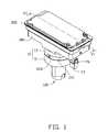
- FIG. 1is an isometric view of an embodiment of an instant clamping mechanism clamping a workpiece.
- FIG. 2is similar to FIG. 1 , but viewed from another aspect.
- FIG. 3is a side view of the instant clamping mechanism of FIG. 1 clamping a workpiece.
- FIG. 4is an exploded, isometric view of the instant clamping mechanism of FIG. 1 with a workpiece.
- FIG. 5is similar to FIG. 3 , but viewed from another aspect.
- FIG. 6is a cross sectional view of the instant clamping mechanism taken along line VI-VI of FIG. 1 .
- FIGS. 1 through 5show an embodiment of an instant clamping mechanism 100 for positioning a workpiece 200 to be machined on a machine support (not shown).
- the instant clamping mechanism 100includes a base seat 10 , a supporting member 30 , a clamping assembly 50 , and a handle assembly 70 .
- the base seat 10is fixed to the machine support and defines a sliding groove 103 along a peripheral surface thereof.
- the supporting member 30is fixed to the base seat 10 .
- the clamping assembly 50extends through the base seat 10 and the supporting member 30 , and protrudes from the supporting member 30 to position the workpiece 200 .
- the handle assembly 70is inserted into the sliding groove 103 and is non-rotatably connected to the clamping assembly 50 .
- the handle assembly 70slides along the sliding groove 103 and rotates the clamping assembly 50 to enable the clamping assembly 50 to move axially in the base seat 10 , thereby clamping or releasing the workpiece 200 .
- the base seat 10includes a seating body 11 and a cover 13 assembled to the seating body 11 .
- the seating body 11includes a first fixing portion 113 and a second fixing portion 115 .
- the first fixing portion 113is in the shape of a post and fixed to the machine support.
- the second fixing portion 115is in a disk shape and coaxially connected to an end of the first fixing portion 113 .
- the second fixing portion 115has a diameter greater than that of the first fixing portion 113 .
- the second fixing portion 115defines a first receiving groove 1151 , a first guiding groove 116 , and an inserting hole 118 on an end thereof away from the first fixing portion 113 .
- the first receiving groove 1151is located at a middle of the end of the second fixing portion 115 ; the first guiding groove 116 is defined along a periphery of that end of the second fixing portion 115 and communicates with the first receiving groove 1151 .
- the inserting hole 118is defined in a bottom of the first receiving groove 1151 and extends into the first fixing portion 113 .
- the second fixing portion 115further includes a pair of posts 1157 symmetrically arranged at a periphery thereof.
- the first guiding groove 116is recessed from the periphery of the second fixing portion 115 and located between the pair of posts 1157 .
- a central angle of the second fixing portion 115 subtended by the first guiding groove 116is about 90 degrees.
- the first guiding groove 116defines a first inclining surface 1161 at a bottom thereof, and defines a latching groove 119 at an end of the first inclining surfaced 1161 .
- the latching groove 119communicates with the first receiving groove 1151 .
- the cover 13is in a disk shape and assembled to the second fixing portion 115 .
- the cover 13defines a second receiving groove 131 , a second guiding groove 135 , and a pair of positioning holes 136 at an end of the cover 13 facing the seating body 11 .
- the second receiving groove 131is defined in a middle of the end of the cover 13 corresponding to the first receiving groove 1151 .
- the first receiving groove 1151 and the second receiving groove 131cooperatively form a receiving chamber 101 .
- the second guiding groove 135is defined along a periphery of the cover 13 corresponding to the first guiding groove 116 which communicates with the second receiving groove 131 .
- a central angle of the cover 13 subtended by the second guiding groove 135is about 90 degrees.
- the second guiding groove 135defines a second inclining surface 1351 at a bottom of the cover 13 parallel to the first inclining surface 1161 .
- the first guiding groove 116 and the second guiding groove 135cooperatively form the sliding groove 103 .
- the sliding groove 103is inclined toward the first fixing portion 113 , and includes a releasing end 1031 and a latching end 1033 (see FIG. 2 ) opposite to the releasing end 1031 .
- the releasing end 1031is located away from the first fixing portion 113
- the latching end 1033is located adjacent to the first fixing portion 113 .
- An axial distance within the base seat 10is defined from the releasing end 1031 to the latching end 1033 .
- the latching groove 119is defined on the releasing end 1031 .
- the positioning holes 136are arranged along a periphery of the cover 13 for receiving the posts 1157 .
- the cover 13further includes a positioning support 137 at an end thereof away from the seating body 11 and defines a stepped hole 139 on a bottom of the second receiving groove 131 .
- the stepped hole 139cuts through the positioning support 137 and forms an annular resisting surface 1391 (see FIG. 6 ) in a middle portion thereof.
- the supporting member 30is assembled to the cover 13 , and receives the positioning support 137 .
- the supporting member 30is substantially rectangular, and defines an accommodating groove 31 in a middle portion thereof.
- the accommodating groove 31is rectangular.
- the supporting member 30further defines a guiding hole 33 at a bottom of the accommodating groove 31 and includes a pair of position protrusions 35 arranged at opposite ends of the accommodating groove 31 for positioning the workpiece 200 .
- the positioning support 137is received in the guiding hole 33 .
- the clamping assembly 50includes a clamping rod 51 , and a resilient member 53 sleeved on an end of the clamping rod 51 .
- the clamping rod 51extends through the inserting hole 118 and the stepped hole 139 , and extends out from the stepped hole 139 to connect with a clamping insert 513 .
- the clamping rod 51radially defines a fixing hole 515 at a middle portion thereof.
- the resilient member 53is received in the stepped hole 139 of the cover 13 and resists against the annular resisting surface 1391 .
- the handle assembly 70includes a handle rod 71 , an operating member 73 , an elastic member 75 , a sliding rod 76 , and a latching member 77 .
- the handle rod 71includes a first mounting portion 711 and a second mounting portion 713 coaxial with the first mounting portion 711 .
- the first mounting portion 711has a diameter less than that of the second mounting portion 713 .
- the first mounting portion 711is received in the receiving chamber 101 and assembled into the fixing hole 515 .
- the second mounting portion 713is a hollow cylindrical shell exposed from the sliding groove 103 , and radially defines a movable hole 7131 thereon adjacent to the first mounting portion 711 .
- the operating member 73is assembled to an end of the second mounting portion 713 away from the first mounting portion 711 , to favor the operator.
- the elastic member 75is received in the second mounting portion 713 and resists the first mounting portion 711 .
- the sliding rod 76is slidably received in the second mounting portion 713 and resists the elastic member 75 toward the first mounting portion 711 . An end of the sliding rod 76 extends out of the second mounting portion 713 .
- the latching member 77is mounted on the end of the sliding rod 76 adjacent to the elastic member 75 , and is exposed out of the movable hole 7131 .
- the latching member 77latches in the latching groove 119 of the seating body 11 .
- the clamping rod 51can be rotated about 90 degrees by the handle assembly 70 .
- the cover 13is assembled to the supporting member 30 .
- the clamping rod 51extends through the stepped hole 139 .
- the clamping insert 513is assembled to the end of the clamping rod 51 extending out from the stepped hole 139 .
- the resilient member 53is sleeved on the clamping rod 51 .
- the elastic member 75 and the sliding rod 76are received in the second mounting portion 713 in that order.
- the latching member 77is assembled into the sliding rod 76 and exposed out of the movable hole 7131 .
- the operating member 73is sleeved on the second mounting portion 713 .
- the first mounting portion 711extends through the fixing hole 515 and is fixed to the clamping rod 51 .
- the seating body 11is assembled to the cover 13 , and the end of the clamping rod 51 away from the cover 13 is assembled into the inserting hole 118 .
- the first receiving groove 1151 and the second receiving groove 131cooperatively form the receiving chamber 101 , the first guiding groove 116 and the second guiding groove 135 form the sliding groove 103 .
- the workpiece 200includes a base body 201 and a mounting block 203 assembled to the base body 201 .
- the mounting block 203is substantially rectangular and has a shape and size corresponding to those of the accommodating groove 31 .
- the mounting block 203defines a mounting groove 2031 facing the base body 201 and a mounting hole 2033 on a bottom of the mounting groove 2031 .
- the mounting hole 2033is substantially in a strip shape and extends longitudinally along the mounting block 203 .
- the first fixing portion 113 of the seating body 10is fixed to the machine support.
- the handle assembly 70is located at the releasing end 1031 of the sliding groove 103 .
- the mounting block 203is received in the accommodating groove 31 .
- the clamping insert 513extends out of the mounting hole 2033 .
- the operating member 73is pushed and the handle assembly 70 is rotated from the releasing end 1031 to the latching end 1033 .
- the clamping rod 51is rotated by the handle assembly 70 to rotate about 90 degrees. In the rotating process thereof, the clamping rod 51 also moves axially within the base seat 10 away from the supporting member 30 , thereby driving the clamping insert 513 to resist a bottom of the mounting groove 2031 .
- the latching member 77is resisted by the elastic member 75 , and latches into the latching groove 119 , such that the workpiece 200 is clamped by the instant clamping mechanism 100 .
- a forceis applied to the sliding rod 76 to push the latching member 77 toward the receiving chamber 101 , thereby detaching the latching member 77 from the latching groove 119 .
- the handle assembly 70is then rotated to the releasing end 1031 , the clamping rod 51 is rotated by the handle assembly 70 and drives the clamping insert 513 to be aligned to the mounting hole 2033 . Then the clamping insert 513 is pulled out of the mounting block 203 through the mounting hole 2033 to release the workpiece 200 .
- the sliding groove 103may be formed on the seating body 11 or the cover 13 .
- the shape of the sliding groove 103may be spiral.
- the base seat 10may be integrally formed with the sliding groove 103 defined at a periphery thereof.
Landscapes
- Engineering & Computer Science (AREA)
- Mechanical Engineering (AREA)
- Jigs For Machine Tools (AREA)
- Press Drives And Press Lines (AREA)
- Automatic Assembly (AREA)
Abstract
Description
- 1. Technical Field
- The present disclosure relates to a clamping mechanism, and more particularly, to an instant clamping mechanism.
- 2. Description of Related Art
- In industrial manufacturing, workpieces are required to be stably clamped in a plurality of machining processes. A nut and a screw rod are commonly employed to clamp the workpieces. When releasing the workpiece after clamping, the nut is rotated to disengage from the screw rod. It is inconvenient and the efficiency is relatively low.
- Therefore, there is room for improvement in the art.
- The components in the drawings are not necessarily drawn to scale, the emphasis instead placed upon clearly illustrating the principles of the present disclosure. Moreover, in the drawings, like reference numerals designate corresponding parts throughout the several views.
FIG. 1 is an isometric view of an embodiment of an instant clamping mechanism clamping a workpiece.FIG. 2 is similar toFIG. 1 , but viewed from another aspect.FIG. 3 is a side view of the instant clamping mechanism ofFIG. 1 clamping a workpiece.FIG. 4 is an exploded, isometric view of the instant clamping mechanism ofFIG. 1 with a workpiece.FIG. 5 is similar toFIG. 3 , but viewed from another aspect.FIG. 6 is a cross sectional view of the instant clamping mechanism taken along line VI-VI ofFIG. 1 .FIGS. 1 through 5 show an embodiment of aninstant clamping mechanism 100 for positioning aworkpiece 200 to be machined on a machine support (not shown). Theinstant clamping mechanism 100 includes abase seat 10, a supportingmember 30, aclamping assembly 50, and ahandle assembly 70. Thebase seat 10 is fixed to the machine support and defines asliding groove 103 along a peripheral surface thereof. The supportingmember 30 is fixed to thebase seat 10. Theclamping assembly 50 extends through thebase seat 10 and the supportingmember 30, and protrudes from the supportingmember 30 to position theworkpiece 200. Thehandle assembly 70 is inserted into thesliding groove 103 and is non-rotatably connected to theclamping assembly 50. Thehandle assembly 70 slides along thesliding groove 103 and rotates theclamping assembly 50 to enable theclamping assembly 50 to move axially in thebase seat 10, thereby clamping or releasing theworkpiece 200.- The
base seat 10 includes aseating body 11 and acover 13 assembled to theseating body 11. Theseating body 11 includes afirst fixing portion 113 and asecond fixing portion 115. Thefirst fixing portion 113 is in the shape of a post and fixed to the machine support. Thesecond fixing portion 115 is in a disk shape and coaxially connected to an end of thefirst fixing portion 113. Thesecond fixing portion 115 has a diameter greater than that of thefirst fixing portion 113. Thesecond fixing portion 115 defines afirst receiving groove 1151, a first guidinggroove 116, and aninserting hole 118 on an end thereof away from thefirst fixing portion 113. The first receivinggroove 1151 is located at a middle of the end of thesecond fixing portion 115; the first guidinggroove 116 is defined along a periphery of that end of thesecond fixing portion 115 and communicates with the first receivinggroove 1151. Theinserting hole 118 is defined in a bottom of the first receivinggroove 1151 and extends into thefirst fixing portion 113. Thesecond fixing portion 115 further includes a pair ofposts 1157 symmetrically arranged at a periphery thereof. The first guidinggroove 116 is recessed from the periphery of thesecond fixing portion 115 and located between the pair ofposts 1157. A central angle of thesecond fixing portion 115 subtended by the first guidinggroove 116 is about 90 degrees. The first guidinggroove 116 defines a first incliningsurface 1161 at a bottom thereof, and defines alatching groove 119 at an end of the first inclining surfaced1161. Thelatching groove 119 communicates with the first receivinggroove 1151. - The
cover 13 is in a disk shape and assembled to thesecond fixing portion 115. Thecover 13 defines a second receivinggroove 131, a second guidinggroove 135, and a pair ofpositioning holes 136 at an end of thecover 13 facing theseating body 11. The second receivinggroove 131 is defined in a middle of the end of thecover 13 corresponding to the first receivinggroove 1151. Also referring toFIG. 6 , the first receivinggroove 1151 and the second receivinggroove 131 cooperatively form areceiving chamber 101. The second guidinggroove 135 is defined along a periphery of thecover 13 corresponding to the first guidinggroove 116 which communicates with the second receivinggroove 131. A central angle of thecover 13 subtended by the second guidinggroove 135 is about 90 degrees. The second guidinggroove 135 defines a secondinclining surface 1351 at a bottom of thecover 13 parallel to the firstinclining surface 1161. The first guidinggroove 116 and the second guidinggroove 135 cooperatively form thesliding groove 103. Thesliding groove 103 is inclined toward thefirst fixing portion 113, and includes a releasingend 1031 and a latching end1033 (seeFIG. 2 ) opposite to the releasingend 1031. The releasingend 1031 is located away from thefirst fixing portion 113, and thelatching end 1033 is located adjacent to thefirst fixing portion 113. An axial distance within thebase seat 10 is defined from the releasingend 1031 to thelatching end 1033. Thelatching groove 119 is defined on the releasingend 1031. Thepositioning holes 136 are arranged along a periphery of thecover 13 for receiving theposts 1157. Thecover 13 further includes apositioning support 137 at an end thereof away from theseating body 11 and defines astepped hole 139 on a bottom of the second receivinggroove 131. Thestepped hole 139 cuts through thepositioning support 137 and forms an annular resisting surface1391 (seeFIG. 6 ) in a middle portion thereof. - The supporting
member 30 is assembled to thecover 13, and receives thepositioning support 137. The supportingmember 30 is substantially rectangular, and defines anaccommodating groove 31 in a middle portion thereof. Theaccommodating groove 31 is rectangular. The supportingmember 30 further defines a guidinghole 33 at a bottom of theaccommodating groove 31 and includes a pair ofposition protrusions 35 arranged at opposite ends of theaccommodating groove 31 for positioning theworkpiece 200. Thepositioning support 137 is received in the guidinghole 33. - The
clamping assembly 50 includes aclamping rod 51, and aresilient member 53 sleeved on an end of theclamping rod 51. Theclamping rod 51 extends through theinserting hole 118 and thestepped hole 139, and extends out from thestepped hole 139 to connect with aclamping insert 513. Theclamping rod 51 radially defines afixing hole 515 at a middle portion thereof. Theresilient member 53 is received in thestepped hole 139 of thecover 13 and resists against the annular resistingsurface 1391. - An end of the
handle assembly 70 extends into the slidinggroove 103 and the fixinghole 515, and is fixed in the clampingrod 51, the other end of thehandle assembly 70 extends out of thebase seat 10. Theresilient member 53 resists between the annular resistingsurface 1391 and thehandle assembly 70. Thehandle assembly 70 includes ahandle rod 71, an operatingmember 73, anelastic member 75, a slidingrod 76, and a latchingmember 77. Thehandle rod 71 includes a first mountingportion 711 and a second mountingportion 713 coaxial with the first mountingportion 711. The first mountingportion 711 has a diameter less than that of the second mountingportion 713. The first mountingportion 711 is received in the receivingchamber 101 and assembled into the fixinghole 515. Thesecond mounting portion 713 is a hollow cylindrical shell exposed from the slidinggroove 103, and radially defines amovable hole 7131 thereon adjacent to the first mountingportion 711. The operatingmember 73 is assembled to an end of the second mountingportion 713 away from the first mountingportion 711, to favor the operator. Theelastic member 75 is received in the second mountingportion 713 and resists the first mountingportion 711. The slidingrod 76 is slidably received in the second mountingportion 713 and resists theelastic member 75 toward the first mountingportion 711. An end of the slidingrod 76 extends out of the second mountingportion 713. The latchingmember 77 is mounted on the end of the slidingrod 76 adjacent to theelastic member 75, and is exposed out of themovable hole 7131. When thehandle assembly 70 is rotated to arrive at thelatching end 1033, the latchingmember 77 latches in the latchinggroove 119 of theseating body 11. In the embodiment, the clampingrod 51 can be rotated about 90 degrees by thehandle assembly 70. - In assembly, the
cover 13 is assembled to the supportingmember 30. The clampingrod 51 extends through the steppedhole 139. The clampinginsert 513 is assembled to the end of the clampingrod 51 extending out from the steppedhole 139. Theresilient member 53 is sleeved on the clampingrod 51. Theelastic member 75 and the slidingrod 76 are received in the second mountingportion 713 in that order. The latchingmember 77 is assembled into the slidingrod 76 and exposed out of themovable hole 7131. The operatingmember 73 is sleeved on the second mountingportion 713. The first mountingportion 711 extends through the fixinghole 515 and is fixed to the clampingrod 51. Theseating body 11 is assembled to thecover 13, and the end of the clampingrod 51 away from thecover 13 is assembled into the insertinghole 118. Thefirst receiving groove 1151 and thesecond receiving groove 131 cooperatively form the receivingchamber 101, thefirst guiding groove 116 and thesecond guiding groove 135 form the slidinggroove 103. - Referring to
FIG. 3 again, theworkpiece 200 includes abase body 201 and amounting block 203 assembled to thebase body 201. The mountingblock 203 is substantially rectangular and has a shape and size corresponding to those of theaccommodating groove 31. The mountingblock 203 defines a mountinggroove 2031 facing thebase body 201 and a mountinghole 2033 on a bottom of the mountinggroove 2031. The mountinghole 2033 is substantially in a strip shape and extends longitudinally along the mountingblock 203. - In use, the
first fixing portion 113 of theseating body 10 is fixed to the machine support. Thehandle assembly 70 is located at the releasingend 1031 of the slidinggroove 103. The mountingblock 203 is received in theaccommodating groove 31. The clampinginsert 513 extends out of the mountinghole 2033. The operatingmember 73 is pushed and thehandle assembly 70 is rotated from the releasingend 1031 to thelatching end 1033. The clampingrod 51 is rotated by thehandle assembly 70 to rotate about 90 degrees. In the rotating process thereof, the clampingrod 51 also moves axially within thebase seat 10 away from the supportingmember 30, thereby driving theclamping insert 513 to resist a bottom of the mountinggroove 2031. The latchingmember 77 is resisted by theelastic member 75, and latches into the latchinggroove 119, such that theworkpiece 200 is clamped by theinstant clamping mechanism 100. When releasing theworkpiece 200 by theinstant clamping mechanism 100, a force is applied to the slidingrod 76 to push the latchingmember 77 toward the receivingchamber 101, thereby detaching the latchingmember 77 from the latchinggroove 119. Thehandle assembly 70 is then rotated to the releasingend 1031, the clampingrod 51 is rotated by thehandle assembly 70 and drives the clampinginsert 513 to be aligned to the mountinghole 2033. Then the clampinginsert 513 is pulled out of the mountingblock 203 through the mountinghole 2033 to release theworkpiece 200. - The sliding
groove 103 may be formed on theseating body 11 or thecover 13. The shape of the slidinggroove 103 may be spiral. Thebase seat 10 may be integrally formed with the slidinggroove 103 defined at a periphery thereof. When thehandle assembly 70 is held on thelatching end 1033 by a sufficient amount of frictional forces, the latchinggroove 119, the slidingrod 76, theelastic member 75, and the latchingmember 77 may be omitted, respectively. - Finally, while various embodiments have been described and illustrated, the disclosure is not to be construed as being limited thereto. Various modifications can be made to the embodiments by those skilled in the art without departing from the true spirit and scope of the disclosure as defined by the appended claims.
Claims (20)
Applications Claiming Priority (3)
| Application Number | Priority Date | Filing Date | Title |
|---|---|---|---|
| CN2012104199759 | 2012-10-29 | ||
| CN201210419975.9ACN103786048B (en) | 2012-10-29 | 2012-10-29 | Fast compressing device |
| CN201210419975 | 2012-10-29 |
Publications (2)
| Publication Number | Publication Date |
|---|---|
| US20140117605A1true US20140117605A1 (en) | 2014-05-01 |
| US9393654B2 US9393654B2 (en) | 2016-07-19 |
Family
ID=50546311
Family Applications (1)
| Application Number | Title | Priority Date | Filing Date |
|---|---|---|---|
| US14/014,811Expired - Fee RelatedUS9393654B2 (en) | 2012-10-29 | 2013-08-30 | Instant clamping mechanism |
Country Status (3)
| Country | Link |
|---|---|
| US (1) | US9393654B2 (en) |
| CN (1) | CN103786048B (en) |
| TW (1) | TW201416167A (en) |
Cited By (2)
| Publication number | Priority date | Publication date | Assignee | Title |
|---|---|---|---|---|
| USD842350S1 (en)* | 2017-04-07 | 2019-03-05 | Nagaki Seiki Co., Ltd. | Supporting device for clamping mechanism |
| CN119147646A (en)* | 2024-11-19 | 2024-12-17 | 四川鑫跃鑫科学仪器有限公司 | Pipeline damage detection device |
Families Citing this family (2)
| Publication number | Priority date | Publication date | Assignee | Title |
|---|---|---|---|---|
| CN112338584B (en)* | 2019-08-08 | 2022-11-01 | 富鼎电子科技(嘉善)有限公司 | Clamping device |
| CN113945435B (en)* | 2020-07-15 | 2024-05-17 | 深圳华大智造科技股份有限公司 | Consumables clamping device and sample handling system |
Citations (7)
| Publication number | Priority date | Publication date | Assignee | Title |
|---|---|---|---|---|
| US3741573A (en)* | 1971-07-12 | 1973-06-26 | S Treer | Tool holder for a machine tool or the like |
| US4813829A (en)* | 1988-03-22 | 1989-03-21 | Sandvik, Inc. | Tooling apparatus comprising a holder and tool head releasably mounted thereon |
| US5417409A (en)* | 1994-04-06 | 1995-05-23 | Reddell; Glen R. | Vise with sliding back jaw |
| US6623015B2 (en)* | 2000-08-25 | 2003-09-23 | System 3R International Ab | Clamping chuck |
| US6957808B2 (en)* | 2001-11-13 | 2005-10-25 | Wmh Tool Group, Inc. | Apparatus for securing a workpiece |
| US7044462B2 (en)* | 2003-05-02 | 2006-05-16 | Kabushiki Kaisha Imao Corporation | Fixture |
| US7338599B2 (en)* | 2000-05-12 | 2008-03-04 | Pall Corporation | Filtration systems and fitting arrangements for filtration systems |
Family Cites Families (7)
| Publication number | Priority date | Publication date | Assignee | Title |
|---|---|---|---|---|
| US4682521A (en)* | 1986-02-10 | 1987-07-28 | Duenas Oswaldo A | Quick change, adjustable tool holder |
| CN101337340B (en) | 2007-07-06 | 2011-06-08 | 鸿富锦精密工业(深圳)有限公司 | Clamp |
| CN201244741Y (en)* | 2008-08-15 | 2009-05-27 | 王铭宏 | Air oil pressure clamp |
| EP2489464B1 (en)* | 2009-10-13 | 2013-12-04 | Kosmek Ltd. | Clamp device |
| CN102233537B (en)* | 2010-04-27 | 2015-03-11 | 南京德朔实业有限公司 | Hand-held power tool with quick clamping device for working element |
| CN102672634B (en) | 2011-03-14 | 2014-04-16 | 富泰华工业(深圳)有限公司 | Clamping mechanism |
| CN102601645A (en)* | 2012-04-01 | 2012-07-25 | 长子县丹朱缸套有限公司 | Boring fixture for cylinder liners |
- 2012
- 2012-10-29CNCN201210419975.9Apatent/CN103786048B/ennot_activeExpired - Fee Related
- 2012-11-05TWTW101140921Apatent/TW201416167A/enunknown
- 2013
- 2013-08-30USUS14/014,811patent/US9393654B2/ennot_activeExpired - Fee Related
Patent Citations (7)
| Publication number | Priority date | Publication date | Assignee | Title |
|---|---|---|---|---|
| US3741573A (en)* | 1971-07-12 | 1973-06-26 | S Treer | Tool holder for a machine tool or the like |
| US4813829A (en)* | 1988-03-22 | 1989-03-21 | Sandvik, Inc. | Tooling apparatus comprising a holder and tool head releasably mounted thereon |
| US5417409A (en)* | 1994-04-06 | 1995-05-23 | Reddell; Glen R. | Vise with sliding back jaw |
| US7338599B2 (en)* | 2000-05-12 | 2008-03-04 | Pall Corporation | Filtration systems and fitting arrangements for filtration systems |
| US6623015B2 (en)* | 2000-08-25 | 2003-09-23 | System 3R International Ab | Clamping chuck |
| US6957808B2 (en)* | 2001-11-13 | 2005-10-25 | Wmh Tool Group, Inc. | Apparatus for securing a workpiece |
| US7044462B2 (en)* | 2003-05-02 | 2006-05-16 | Kabushiki Kaisha Imao Corporation | Fixture |
Cited By (2)
| Publication number | Priority date | Publication date | Assignee | Title |
|---|---|---|---|---|
| USD842350S1 (en)* | 2017-04-07 | 2019-03-05 | Nagaki Seiki Co., Ltd. | Supporting device for clamping mechanism |
| CN119147646A (en)* | 2024-11-19 | 2024-12-17 | 四川鑫跃鑫科学仪器有限公司 | Pipeline damage detection device |
Also Published As
| Publication number | Publication date |
|---|---|
| CN103786048B (en) | 2016-06-29 |
| US9393654B2 (en) | 2016-07-19 |
| CN103786048A (en) | 2014-05-14 |
| TW201416167A (en) | 2014-05-01 |
Similar Documents
| Publication | Publication Date | Title |
|---|---|---|
| TWI530355B (en) | Tool changing device | |
| US10144110B2 (en) | Work tool | |
| US9393654B2 (en) | Instant clamping mechanism | |
| US8292279B2 (en) | Clamp | |
| US11090800B2 (en) | Tool box | |
| US9381596B2 (en) | Welding fixture | |
| US20140157977A1 (en) | Cylinder mechanism | |
| CN108381298B (en) | Machining device and machining method thereof | |
| US9469002B2 (en) | Clamping device | |
| US8079121B2 (en) | Pressing device for latching and releasing chucking device | |
| US20130033051A1 (en) | Locking mechanism | |
| JP2020006477A (en) | Elastic ring mounting jig | |
| CN215488657U (en) | Clamping assembly and clamping device for clamping mobile equipment | |
| CN105522493A (en) | Clamping device | |
| CN212294877U (en) | A new combination structure of faucet pins | |
| JP2018069423A (en) | Center device | |
| CN217223648U (en) | Chuck assembly of machine tool equipment and machine tool equipment | |
| CN104339289B (en) | Bullet formula latch mechanism | |
| US9199324B2 (en) | Holding wrench | |
| CN220783739U (en) | Screw driver | |
| CN209805619U (en) | Tool for mounting coil spring on brush holder | |
| CN109702525B (en) | Fixing device | |
| TWI790894B (en) | Floating type clamping and positioning device | |
| CN222627470U (en) | Clamping fixture | |
| CN111922761B (en) | a clamping device |
Legal Events
| Date | Code | Title | Description |
|---|---|---|---|
| AS | Assignment | Owner name:FU TAI HUA INDUSTRY (SHENZHEN) CO., LTD., CHINA Free format text:ASSIGNMENT OF ASSIGNORS INTEREST;ASSIGNORS:CHEN, JIA-CHAO;ZHANG, YUN-TAO;XU, XIAO-BING;SIGNING DATES FROM 20130824 TO 20130826;REEL/FRAME:031121/0575 Owner name:HON HAI PRECISION INDUSTRY CO., LTD., TAIWAN Free format text:ASSIGNMENT OF ASSIGNORS INTEREST;ASSIGNORS:CHEN, JIA-CHAO;ZHANG, YUN-TAO;XU, XIAO-BING;SIGNING DATES FROM 20130824 TO 20130826;REEL/FRAME:031121/0575 | |
| STCF | Information on status: patent grant | Free format text:PATENTED CASE | |
| AS | Assignment | Owner name:SHENZHENSHI YUZHAN PRECISION TECHNOLOGY CO., LTD., Free format text:ASSIGNMENT OF ASSIGNORS INTEREST;ASSIGNORS:FU TAI HUA INDUSTRY (SHENZHEN) CO., LTD.;HON HAI PRECISION INDUSTRY CO., LTD.;REEL/FRAME:045222/0101 Effective date:20180117 Owner name:CLOUD NETWORK TECHNOLOGY SINGAPORE PTE. LTD., SING Free format text:ASSIGNMENT OF ASSIGNORS INTEREST;ASSIGNORS:FU TAI HUA INDUSTRY (SHENZHEN) CO., LTD.;HON HAI PRECISION INDUSTRY CO., LTD.;REEL/FRAME:045222/0101 Effective date:20180117 | |
| MAFP | Maintenance fee payment | Free format text:PAYMENT OF MAINTENANCE FEE, 4TH YEAR, LARGE ENTITY (ORIGINAL EVENT CODE: M1551); ENTITY STATUS OF PATENT OWNER: LARGE ENTITY Year of fee payment:4 | |
| AS | Assignment | Owner name:FULIAN YUZHAN PRECISION TECHNOLOGY CO., LTD., CHINA Free format text:CHANGE OF NAME;ASSIGNOR:SHENZHENSHI YUZHAN PRECISION TECHNOLOGY CO., LTD.;REEL/FRAME:061357/0276 Effective date:20220302 | |
| FEPP | Fee payment procedure | Free format text:MAINTENANCE FEE REMINDER MAILED (ORIGINAL EVENT CODE: REM.); ENTITY STATUS OF PATENT OWNER: LARGE ENTITY | |
| LAPS | Lapse for failure to pay maintenance fees | Free format text:PATENT EXPIRED FOR FAILURE TO PAY MAINTENANCE FEES (ORIGINAL EVENT CODE: EXP.); ENTITY STATUS OF PATENT OWNER: LARGE ENTITY | |
| STCH | Information on status: patent discontinuation | Free format text:PATENT EXPIRED DUE TO NONPAYMENT OF MAINTENANCE FEES UNDER 37 CFR 1.362 | |
| FP | Lapsed due to failure to pay maintenance fee | Effective date:20240719 |