US20140018816A1 - Torque transmitting ball joint driver having a rigid fixation mechanism - Google Patents
Torque transmitting ball joint driver having a rigid fixation mechanismDownload PDFInfo
- Publication number
- US20140018816A1 US20140018816A1US13/547,540US201213547540AUS2014018816A1US 20140018816 A1US20140018816 A1US 20140018816A1US 201213547540 AUS201213547540 AUS 201213547540AUS 2014018816 A1US2014018816 A1US 2014018816A1
- Authority
- US
- United States
- Prior art keywords
- driver
- spherical head
- input shaft
- bushing
- screw
- Prior art date
- Legal status (The legal status is an assumption and is not a legal conclusion. Google has not performed a legal analysis and makes no representation as to the accuracy of the status listed.)
- Abandoned
Links
- 230000007246mechanismEffects0.000titledescription7
- 230000014759maintenance of locationEffects0.000claimsabstractdescription35
- 230000003993interactionEffects0.000claimsdescription11
- 230000000295complement effectEffects0.000claimsdescription9
- 230000009471actionEffects0.000claimsdescription5
- 210000000988bone and boneAnatomy0.000description14
- 238000000034methodMethods0.000description5
- 239000004696Poly ether ether ketoneSubstances0.000description4
- 230000008878couplingEffects0.000description4
- 238000010168coupling processMethods0.000description4
- 238000005859coupling reactionMethods0.000description4
- 239000000463materialSubstances0.000description4
- 229920002530polyetherether ketonePolymers0.000description4
- 239000010935stainless steelSubstances0.000description4
- 229910001220stainless steelInorganic materials0.000description4
- 238000003780insertionMethods0.000description3
- 230000037431insertionEffects0.000description3
- 229910052751metalInorganic materials0.000description3
- 239000002184metalSubstances0.000description3
- 239000011295pitchSubstances0.000description3
- 230000000717retained effectEffects0.000description3
- 229910001069Ti alloyInorganic materials0.000description2
- RTAQQCXQSZGOHL-UHFFFAOYSA-NTitaniumChemical compound[Ti]RTAQQCXQSZGOHL-UHFFFAOYSA-N0.000description2
- 230000005540biological transmissionEffects0.000description2
- 239000000919ceramicSubstances0.000description2
- 230000004927fusionEffects0.000description2
- 125000006850spacer groupChemical group0.000description2
- 239000010936titaniumSubstances0.000description2
- 229910052719titaniumInorganic materials0.000description2
- 239000004698PolyethyleneSubstances0.000description1
- 229910000639Spring steelInorganic materials0.000description1
- ATJFFYVFTNAWJD-UHFFFAOYSA-NTinChemical compound[Sn]ATJFFYVFTNAWJD-UHFFFAOYSA-N0.000description1
- 238000005452bendingMethods0.000description1
- 230000008901benefitEffects0.000description1
- 238000004140cleaningMethods0.000description1
- 239000011248coating agentSubstances0.000description1
- 238000000576coating methodMethods0.000description1
- 238000010276constructionMethods0.000description1
- 229920002457flexible plasticPolymers0.000description1
- 229910001000nickel titaniumInorganic materials0.000description1
- HLXZNVUGXRDIFK-UHFFFAOYSA-Nnickel titaniumChemical compound[Ti].[Ti].[Ti].[Ti].[Ti].[Ti].[Ti].[Ti].[Ti].[Ti].[Ti].[Ni].[Ni].[Ni].[Ni].[Ni].[Ni].[Ni].[Ni].[Ni].[Ni].[Ni].[Ni].[Ni].[Ni]HLXZNVUGXRDIFK-UHFFFAOYSA-N0.000description1
- 239000004033plasticSubstances0.000description1
- 229920003023plasticPolymers0.000description1
- -1polyethylenePolymers0.000description1
- 229920000573polyethylenePolymers0.000description1
- 229920000642polymerPolymers0.000description1
- 239000007787solidSubstances0.000description1
- 238000001356surgical procedureMethods0.000description1
- 210000001519tissueAnatomy0.000description1
Images


Classifications
- A—HUMAN NECESSITIES
- A61—MEDICAL OR VETERINARY SCIENCE; HYGIENE
- A61B—DIAGNOSIS; SURGERY; IDENTIFICATION
- A61B17/00—Surgical instruments, devices or methods
- A61B17/16—Instruments for performing osteoclasis; Drills or chisels for bones; Trepans
- A61B17/1613—Component parts
- A61B17/162—Chucks or tool parts which are to be held in a chuck
- A—HUMAN NECESSITIES
- A61—MEDICAL OR VETERINARY SCIENCE; HYGIENE
- A61B—DIAGNOSIS; SURGERY; IDENTIFICATION
- A61B17/00—Surgical instruments, devices or methods
- A61B17/16—Instruments for performing osteoclasis; Drills or chisels for bones; Trepans
- A61B17/17—Guides or aligning means for drills, mills, pins or wires
- A61B17/1739—Guides or aligning means for drills, mills, pins or wires specially adapted for particular parts of the body
- A61B17/1757—Guides or aligning means for drills, mills, pins or wires specially adapted for particular parts of the body for the spine
- A—HUMAN NECESSITIES
- A61—MEDICAL OR VETERINARY SCIENCE; HYGIENE
- A61B—DIAGNOSIS; SURGERY; IDENTIFICATION
- A61B17/00—Surgical instruments, devices or methods
- A61B17/56—Surgical instruments or methods for treatment of bones or joints; Devices specially adapted therefor
- A61B17/58—Surgical instruments or methods for treatment of bones or joints; Devices specially adapted therefor for osteosynthesis, e.g. bone plates, screws or setting implements
- A61B17/68—Internal fixation devices, including fasteners and spinal fixators, even if a part thereof projects from the skin
- A61B17/70—Spinal positioners or stabilisers, e.g. stabilisers comprising fluid filler in an implant
- A61B17/7074—Tools specially adapted for spinal fixation operations other than for bone removal or filler handling
- A61B17/7076—Tools specially adapted for spinal fixation operations other than for bone removal or filler handling for driving, positioning or assembling spinal clamps or bone anchors specially adapted for spinal fixation
- A—HUMAN NECESSITIES
- A61—MEDICAL OR VETERINARY SCIENCE; HYGIENE
- A61B—DIAGNOSIS; SURGERY; IDENTIFICATION
- A61B17/00—Surgical instruments, devices or methods
- A61B17/56—Surgical instruments or methods for treatment of bones or joints; Devices specially adapted therefor
- A61B17/58—Surgical instruments or methods for treatment of bones or joints; Devices specially adapted therefor for osteosynthesis, e.g. bone plates, screws or setting implements
- A61B17/88—Osteosynthesis instruments; Methods or means for implanting or extracting internal or external fixation devices
- A61B17/8875—Screwdrivers, spanners or wrenches
- B—PERFORMING OPERATIONS; TRANSPORTING
- B25—HAND TOOLS; PORTABLE POWER-DRIVEN TOOLS; MANIPULATORS
- B25B—TOOLS OR BENCH DEVICES NOT OTHERWISE PROVIDED FOR, FOR FASTENING, CONNECTING, DISENGAGING OR HOLDING
- B25B23/00—Details of, or accessories for, spanners, wrenches, screwdrivers
- B25B23/0007—Connections or joints between tool parts
- B25B23/0035—Connection means between socket or screwdriver bit and tool
- B—PERFORMING OPERATIONS; TRANSPORTING
- B25—HAND TOOLS; PORTABLE POWER-DRIVEN TOOLS; MANIPULATORS
- B25B—TOOLS OR BENCH DEVICES NOT OTHERWISE PROVIDED FOR, FOR FASTENING, CONNECTING, DISENGAGING OR HOLDING
- B25B23/00—Details of, or accessories for, spanners, wrenches, screwdrivers
- B25B23/02—Arrangements for handling screws or nuts
- B25B23/08—Arrangements for handling screws or nuts for holding or positioning screw or nut prior to or during its rotation
- B25B23/10—Arrangements for handling screws or nuts for holding or positioning screw or nut prior to or during its rotation using mechanical gripping means
- F—MECHANICAL ENGINEERING; LIGHTING; HEATING; WEAPONS; BLASTING
- F16—ENGINEERING ELEMENTS AND UNITS; GENERAL MEASURES FOR PRODUCING AND MAINTAINING EFFECTIVE FUNCTIONING OF MACHINES OR INSTALLATIONS; THERMAL INSULATION IN GENERAL
- F16D—COUPLINGS FOR TRANSMITTING ROTATION; CLUTCHES; BRAKES
- F16D3/00—Yielding couplings, i.e. with means permitting movement between the connected parts during the drive
- F16D3/16—Universal joints in which flexibility is produced by means of pivots or sliding or rolling connecting parts
- F16D3/20—Universal joints in which flexibility is produced by means of pivots or sliding or rolling connecting parts one coupling part entering a sleeve of the other coupling part and connected thereto by sliding or rolling members
- F16D3/202—Universal joints in which flexibility is produced by means of pivots or sliding or rolling connecting parts one coupling part entering a sleeve of the other coupling part and connected thereto by sliding or rolling members one coupling part having radially projecting pins, e.g. tripod joints
- F16D3/207—Universal joints in which flexibility is produced by means of pivots or sliding or rolling connecting parts one coupling part entering a sleeve of the other coupling part and connected thereto by sliding or rolling members one coupling part having radially projecting pins, e.g. tripod joints the pins extending radially inwardly from the coupling part
- A—HUMAN NECESSITIES
- A61—MEDICAL OR VETERINARY SCIENCE; HYGIENE
- A61B—DIAGNOSIS; SURGERY; IDENTIFICATION
- A61B17/00—Surgical instruments, devices or methods
- A61B17/56—Surgical instruments or methods for treatment of bones or joints; Devices specially adapted therefor
- A61B17/58—Surgical instruments or methods for treatment of bones or joints; Devices specially adapted therefor for osteosynthesis, e.g. bone plates, screws or setting implements
- A61B17/68—Internal fixation devices, including fasteners and spinal fixators, even if a part thereof projects from the skin
- A61B17/70—Spinal positioners or stabilisers, e.g. stabilisers comprising fluid filler in an implant
- A61B17/7074—Tools specially adapted for spinal fixation operations other than for bone removal or filler handling
- A61B17/7076—Tools specially adapted for spinal fixation operations other than for bone removal or filler handling for driving, positioning or assembling spinal clamps or bone anchors specially adapted for spinal fixation
- A61B17/7082—Tools specially adapted for spinal fixation operations other than for bone removal or filler handling for driving, positioning or assembling spinal clamps or bone anchors specially adapted for spinal fixation for driving, i.e. rotating, screws or screw parts specially adapted for spinal fixation, e.g. for driving polyaxial or tulip-headed screws
Definitions
- a metal, polymer, or bone spaceris typically implanted between the two adjoining vertebrae. After these spacers or “cages” are inserted, surgeons often use metal screws, plates, and/or rods to further stabilize the spine. To insert the screws, a driver device having an articulating driver head may be used to deliver the screws to their spinal column and lock them into place.
- a u-jointmay be provided to allow the driver head to articulate with respect to an input shaft.
- the u-jointmay have a range of angulation that makes it difficult for a user to maintain an appropriate force on a component (e.g., a screw) being driven.
- a bushing within the driver head that retains a driver tipmay wear out over time, which causes the driver tip to move around, thus making it difficult for the user to drive the component.
- the present disclosureprovides an articulating driver and for a ball-in-socket joint.
- the drivermay include a driver tip having a spherical head, a retention cap having a domed surface to mate with the spherical head, an input shaft, a spring disposed in an end of the input shaft and in a recess of the retention cap opposite that of the domed surface, and a housing that receives the input shaft, the spring, the retention cap and the spherical head.
- the housingmay have a tapered end to positionally retain the spherical head therein.
- the spherical headhas a plurality of grooves defined in a surface thereof and the housing defines a plurality of holes. Each of the holes may receive a pin that passes through the housing and is received within a respective groove of the spherical head.
- a ball-in-socket jointthat includes an input shaft, a output shaft having a spherical head, the spherical head having a plurality of grooves defined therein, a retention cap having a domed surface to mate with the spherical head, a spring disposed in an end of the input shaft and in a recess of the retention cap opposite that of the domed surface, and a housing that defines a plurality of holes and receives the input shaft, the spring, the retention cap and the spherical head,
- the housingmay have a tapered end to positionally retain the spherical head therein.
- Each of the holesmay receive a pin that passes through the housing and is received within a respective groove of the spherical head.
- a ball-in-socket jointthat includes a housing that defines a plurality of holes, where the housing is tapered at one end.
- the ball-in-socket jointalso may also include an input shaft, a spring disposed in an end of the input shaft that is disposed within the housing, a retention cap disposed with the house that receives the spring at one end and has a domed surface at the other end thereof, and an output shaft having a spherical head that is disposed within the housing.
- the ball shaped headmay have defined therein a plurality of grooves within which pins inserted into the holes or inward protrusions cooperate to transmit torque from the input shaft to the output shaft.
- a driverhaving an input shaft adapted to transmit torque and a driver tip coupled to the input shaft.
- the driver tipmay include an interface defined at an end thereof adapted to engage a screw.
- the drivermay also include a bushing that engages the driver tip at one end and that receives the screw at the other end. The screw may be received within the bushing to engage the interface, and the input shaft is adapted to apply torque to the screw through the interface and to apply torque to the bushing by the engagement of the bushing with the driver tip.
- a method of engaging a screw with a driverhaving an input shaft, a bushing, and a driver tip.
- the methodmay include engaging the bushing with the driver tip; advancing the bushing along a longitudinal axis of the driver tip in a first direction to expose a screw interface; receiving the screw at the screw interface; and moving the bushing in a second direction along the longitudinal axis to couple a head of the screw with the bushing to retain the screw within the driver.
- FIG. 1Aillustrates a driver device having an articulating driver head
- FIG. 1Billustrates a sectional view of the driver device along section line A-A of FIG. 1A ;
- FIG. 1Cillustrates a ball-in-socket joint of the driver devices of FIG. 1A in greater detail
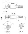
- FIG. 2illustrates a retention cap of FIGS. 1A-1C ;
- FIGS. 3A-3Billustrate a spherical head of FIGS. 1A-1C in greater detail
- FIG. 3Cillustrates a sectional view of the spherical head along section line A-A of FIG. 3B ;
- FIG. 3Dillustrates a sectional view of the spherical head along section line D-D of FIG. 3A ;
- FIG. 4Aillustrates an articulation housing assembly of FIGS. 1A-1C in greater detail
- FIG. 4Billustrates a sectional view of the articulation housing assembly along section line B-B of FIG. 4A ;
- FIG. 4Cillustrates a sectional view of the articulation housing assembly along section line A-A of FIG. 4A ;
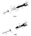
- FIGS. 5-8illustrate an engagement of a screw with a driver device such as that shown in FIG. 1 ;
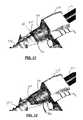
- FIGS. 9-12illustrate an interaction of a stop region of a bushing of the driver device and an aiming device to provide disengagement of the screw from the driver device according to an embodiment
- FIGS. 13-20illustrate an interaction of a stop region of a bushing of the driver device and an aiming device to provide disengagement of the screw from the driver device in accordance with another embodiment
- FIGS. 21-25illustrate another embodiment of the driver device of the present disclosure
- FIG. 26illustrates another embodiment of the driver device of the present disclosure
- FIGS. 27A-27Cillustrate another embodiment of the articulating driver of the present disclosure
- FIGS. 28A-28Cillustrate a first spherical head of the embodiment of FIGS. 27A-27C ;
- FIGS. 29A-29Cillustrate a second spherical head of the embodiment of FIGS. 27A-27C ;
- FIGS. 30A-30Billustrate the articulation housing assembly of the embodiment of FIGS. 27A-27C in greater detail
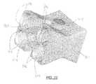
- FIG. 31illustrates a perspective view of the embodiment of FIGS. 27A-27C .
- an articulating driver 100 and a ball-in-socket joint 102there is illustrated an articulating driver 100 and a ball-in-socket joint 102 .
- the ball-in-socket joint 102allows a driver tip 126 or other output shaft to articulate while transmitting input torque from an input shaft 104 to the driver tip 126 .
- the input torqueturns e.g., a screw or other component being driven by the articulating driver 100 .
- the articulating driver 100may be a jointed awl, screw driver or drill.
- the articulating driver 100consists of the input shaft 104 that, at a first end 106 , connects to a handle (not shown) and at a second end 108 connects to an articulation housing assembly 110 that forms an outer portion of the ball-in-socket joint 102 .
- the input shaft 104may be any type of shaft capable of transmitting input torque from the handle or a power tool to which the input shaft 104 is attached.
- a cavity 114is defined that accepts a spring 116 or the cavity walls are composed of a spring.
- the spring 116provides positional retention of the driver tip 126 .
- the retention cap 120transmits force from the spring 116 to a spherical head 124 of the driver tip 126 that is secured between the retention cap 120 and a tapered inner surface 130 of the articulation housing assembly 110 .
- a domed surface 122may be defined at an end of the retention cap 120 opposite the recess 118 to receive the spherical head 124 .
- the articulation housing assembly 110receives the second end 108 of the input shaft 104 , the spring 116 , the retention cap 120 , and the spherical head 124 of the driver tip 126 .
- the articulation housing assembly 110defines holes 136 within which pins 134 a , 134 b and 134 c are pressed. The pins 134 a , 134 b and 134 c are received within grooves 128 a , 128 b and 128 c of the spherical head 124 (see, FIGS. 3A-3D ).
- the spherical head 124transmits torque to an attachment that is received within a bushing 132 (see, FIG. 1A ).
- the bushing 132provides positional retention of the attachment and may be made from Polyether ether ketone (PEEK) or an appropriate plastic or metal.
- the domed surface 122 of the retention cap 120 and the tapered inner surface 130 of the articulation housing assembly 110may each have a radius that is similar to, and designed to interface with the spherical head 124 head of the driver tip 126 . These radii allow the driver tip 126 to articulate within the articulation housing assembly 110 , while retaining the spherical head 124 within the articulation housing assembly 110 .
- the interaction of the spring 116 pressing on the retention cap 120which mates to the spherical head 124 , and the tapered inner surface 130 of the articulation housing assembly 110 serve to positionally retain the driver tip 126 within the articulation housing assembly 110 .
- FIGS. 3A-3Dillustrate the spherical head 124 and the driver tip 126 in greater detail.
- the grooves 128 a , 128 b and 128 cform a generally ovular shape on the surface of the spherical head 124 , and are wider near the diameter and taper moving toward the circumference.
- the grooves 128 a , 128 b and 128 care formed having generally having a W-shape cross-section (see, FIG. 3D ) within spherical head 124 .
- the grooves 128 a , 128 b and 128 cmay be milled into spherical head portion at offsets of 120°.
- the groovesmay extend over an approximately 120° arc across the surface of the spherical head 124 .
- the shape of the grooves 128 a , 128 b and 128 cmaybe any shape such that the grooves cooperate with the pins 134 a , 134 b and 134 c provide approximately 45-50° of angulation of the driver tip 126 with respect to the input shaft 104 over a 360° rotation.
- the input shaft 104is pressed in the articulation housing assembly 110 and cross-pinned to the articulation housing assembly 110 using a pin 112 .
- the pin 112may be pressed-in and retained by an interference fit with the shaft 104 ; the pin 112 may be welded in place, or may be threaded into the shaft 104 or retained within a further sleeve used to prevent pins 112 , 134 a - 134 c from backing out. Other attachment mechanisms may be used in place of the pin 112 .
- the various components abovemay be made from stainless steel, titanium, titanium alloy, ceramic, etc.
- the retention cap 120may be fabricated from PEEK, stainless steel, polyethylene, or any metallic or polymetric material.
- the retention cap 120may also include a TiN coating to limit wear and galling on the spherical head 124 .
- the various components of the driver 100may have the following dimensions.
- the radius of curvature of the domed surface 122may be approximately 3.6 mm and may have a depth of 1.8 mm.
- the spherical head 124 portionmay have a diameter approximately 6.5 mm.
- the recess 118may have a depth of 1.5 mm to receive a portion of the spring 116 .
- the retention cap 120may have a total height of 3.0 mm.
- the articulation housing assemblymay have a length of 15 mm and the tapered inner surface may begin 1.6 mm from the edge of the housing assembly.
- the inner diameter of the articulation housing assemblymay be 7.1 mm.
- the cavity defined in the second end of the input shaftmay have a depth of 3.5 mm.
- the ball-in-socket joint 102 of the present disclosurecan be positioned stabily in a multi-angle screwing/unscrewing operation.
- the driver 100maintains the driver tip 126 within a useful range of operation.
- a bushing 232includes inner threads 506 disposed at a distal end thereof and inner threads 508 disposed at the proximal end thereof.
- the diameter of the inner threads 506 and inner threads 508have a dimension that is complementary with an outer threaded portion 514 of the screw 502 and a threaded region 510 of the driver tip 126 , respectively.
- the pitches of the inner threads 506 and outer threaded portion 514 , and inner threads 508 and a threaded region 510may be respectively optimized to match.
- the outer threaded portion 514may be a conical thread or a straight thread.
- the diameter of the inner threads 506may be larger than the inner threads 508 to allow the inner threads 506 to pass over the threaded region 510 , as will be described below.
- the diameter of the inner threads 506 and the outer threads 508may be the same.
- the bushingfurther includes a stop region 516 , which cooperates with an aiming device or guide to halt forward progress of the bushing 232 within the aiming device when the screw 502 is driven by the articulating driver 100 . Further details of the interaction of the stop region 516 and the aiming device will be described below with reference to FIGS. 9-12 .
- the driver tip 126includes at a distal end thereof a screw interface 512 that is adapted to engage a complementary recess defined within the head the screw 502 .
- the screw interface 512 and complementary recessmay be star-shaped, hexagonal, square, a polygonal shape, etc.
- FIG. 5illustrates the components in a separated state, where initially, the bushing 232 is placed over the screw interface 512 to engage the inner threads 508 with the threaded region 510 .
- the bushing 232is rotated in, e.g., a clockwise direction such that the inner threads 508 mesh with the threaded region 510 to advance the bushing in the proximal direction.
- the bushing 232may be moved in the proximal direction such that the inner threads 506 pass over the threaded region 510 , as the diameter of the inner threads 506 may be larger than the threaded region 510 .
- the inner threads 506may engage the threaded region 510 .
- an intermediate state of engagementis achieved (shown in FIG. 6 ) where the screw interface 512 and a portion of the threaded region 510 protrude through the distal end of the bushing 232 .
- the screw interface 512is positioned such that it can be received within a complementary recess in the head of the screw 502 .
- the screw 502is brought into proximity with the screw interface 512 such that the interface may engage the head of the screw 502 .
- An operatormay then rotate the bushing 232 in e.g., the counterclockwise direction to cause the inner threads 508 to mesh with the threaded region 510 , thus moving the bushing 232 in the distal direction.
- FIG. 8illustrates the screw 502 when loaded into the articulating driver 100 and ready to be driven into an associated plate or portion of bone.
- an aiming device or guide 600may be used to guide the screw 502 .
- the aiming device 600includes a plurality of aiming holes 604 , each having a pin 602 that protrudes through an inner wall thereof at a distal end.
- An operatormay drive the screw 502 into, e.g., bone, by inserting the screw 502 into an appropriate one of the aiming holes 604 .
- the screw 502will pass through the aiming hole 604 and out of the aiming device 600 .
- the aiming device 600is sized such that the bushing 232 remains rotably positioned within a proximal portion of the aiming hole 604 (see, e.g., FIG. 10 ). As the operator drives the screw 502 using the driver 100 , the screw 502 and bushing 232 will rotate and move distally within the aiming hole 604 as the screw 502 engages the plate or bone.
- the distal movementwill cause the stop region 516 of the bushing 232 to engage the pin 602 .
- the stop region 516may be formed having a jagged or zig-zag edge, such that the pin 602 is caught within a vertex 516 a formed by the edge. Engagement of the stop region 516 with the pin 602 will cause the bushing 232 to cease rotational and longitudinal movement (i.e., it will be stopped within the aiming hole 604 ). It is noted that other designs may be used to stop the advancement of the bushing 232 within the aiming hole 604 (e.g., frictional engagement).
- the application of torque to the driver tip 126will continue to rotate the screw 502 within the bushing 232 .
- the screw 502will continue to be driven in the distal direction along the longitudinal axis of the driver tip 126 .
- continuing to drive the screw 502will rotate the threaded region 514 within the inner threads 506 , causing the threaded region 514 to progress out of the distal end of the bushing 232 .
- the screw 502advances from the bushing 232 and will be released from the driver 100 .
- Operation of the articulating driver 100may continue in order to drive the screw 502 into its final position through the continued engagement of the screw interface 512 with the head of the screw 502 . Once the screw 502 reaches its final position, the articulating driver 100 may be withdrawn from the aiming device or guide 600 .
- a bushing 732includes inner threads 706 ( FIG. 14 ) disposed at a distal end thereof and inner threads 708 disposed at the proximal end thereof.
- the diameter of the inner threads 706 and inner threads 708have a dimension that is complementary with an outer threaded portion 514 of the screw 502 and a threaded region 510 of the driver tip 126 , respectively.
- the pitches of the inner threads 706 and outer threaded portion 514 , and inner threads 708 and a threaded region 510may be respectively optimized to match.
- the outer threaded portion 514may be a conical thread or a straight thread.
- the diameter of the inner threads 706may be larger than the inner threads 708 to allow the inner threads 706 to pass over the threaded region 510 , as will be described below.
- the diameter of the inner threads 706 and the outer threads 708may be the same.
- the bushing 732further includes lobes 734 , which cooperate with an aiming device or guide to halt forward progress of the bushing 732 within the aiming device when the screw 502 is driven by the articulating driver 100 .
- the cooperation of the lobes 734 with the aiming deviceis described below in more detail with reference to FIGS. 17-20 .
- the lobes 734may be formed such that they extend outwardly from the circumference of the bushing 732 . Three or four lobes 734 may be provided at the proximal end of the bushing 732 ; however any number of lobes may be provided.
- FIG. 14illustrates the components in a separated state, where initially, the bushing 732 is placed over the screw interface 512 to engage the inner threads 508 with the threaded region 510 .
- the bushing 732is rotated in, e.g., a clockwise direction such that the inner threads 508 mesh with the threaded region 510 to advance the bushing in the proximal direction.
- the bushing 732may be moved in the proximal direction such that the inner threads 506 pass over the threaded region 510 , as the diameter of the inner threads 506 may be larger than the threaded region 510 .
- the inner threads 506may engage the threaded region 510 .
- an intermediate state of engagementis achieved (shown in FIG. 15 ) where the screw interface 512 and a portion of the threaded region 510 protrude through the distal end of the bushing 232 .
- the screw interface 512is positioned such that it can be received within a complementary recess in the head of the screw 502 .
- FIG. 16illustrates the screw 502 when loaded into the articulating driver 100 and ready to be driven into an associated plate or portion of bone.
- an aiming device or guide 800may be used to guide the screw 502 .
- the aiming device 800includes a plurality of aiming holes 804 , each having circumferential lobes 802 at a proximal end.
- the circumferential lobes 802may extend inwardly from a center of each aiming hole 804 and receive the lobes 734 of the bushing 732 .
- An operatormay drive the screw 502 into, e.g., bone, by inserting the screw 502 into an appropriate one of the aiming holes 804 .
- the screw 502will pass through the aiming hole 804 and out of the aiming device 800 .
- the aiming device 800is sized such that the bushing 732 remains rotably positioned within a proximal portion of the aiming hole 804 (see, e.g., FIG. 18 ).
- the screw 502 and bushing 732will rotate and move distally within the aiming hole 804 as the screw 502 engages the plate or bone.
- the distal movementwill cause the lobes 734 of the bushing 732 to be received within the lobes 802 .
- the lobes 734 and the lobes 802may be formed having complementary shapes such that the lobes 734 are received with the complementary shaped lobes 802 . Engagement of the lobes 734 and lobes 802 will cause the bushing 732 to cease rotational and longitudinal movement (i.e., it will be stopped within the aiming hole 804 ).
- the application of torque to the driver tip 126will continue to rotate the screw 502 within the bushing 732 .
- the screw 502will continue to be driving in the distal direction along the longitudinal axis of the driver 100 .
- continuing to drive the screw 502will rotate the threaded region 514 within the inner threads 506 , causing the threaded region 514 to progress out of the distal end of the bushing 732 .
- the screw 502advances from the bushing 732 and will be released from the driver 100 .
- Operation of the articulating driver 100may continue in order to drive the screw 502 into its final position through the continued engagement of the screw interface 512 with the head of the screw 502 . Once the screw 502 reaches its final position, the articulating driver 100 may be withdrawn from the aiming device or guide 800 .
- FIGS. 21-25illustrate another embodiment of an articulating driver 1300 of the present disclosure.
- the articulating driver 1300may include three components, a central screwdriver ( FIG. 21 ), a central sleeve ( FIG. 22 ) and an outer, slip sleeve ( FIG. 23 ).
- the central screwdriver 1301may be a straight or jointed driver.
- the central screwdrivermay be a jointed driver which is composed of a proximal shaft 1301 which has an interface 1301 a that is adapted to provide a connection to, e.g., a handle for applying torque.
- the central screwdrivermay include a jointed feature (e.g., a universal joint 1308 ) and a distal portion containing the screw interface 1306 a (e.g., a self retaining star-drive).
- the joint mechanism 1308may accomplished by beam coupling, spring coupling, jaw coupling, etc.
- the screw interface 1306 amay have a hexagonal, square, polygonal shape, etc.
- the central screwdrivermay include a distal tip 1306 that at a proximal end thereof, includes a circumferential groove 1313 to allow for retention of the central sleeve.
- the central sleevemay include a mechanism 1302 to retain the central sleeve on the central screwdriver of FIG. 21 .
- the mechanism 1302may be a spring-loaded quick coupling with detents for retention on the circumferential groove of the central screwdriver.
- a helical structure 1304may be provided between the proximal end and the distal tip to allow for bending of the jointed segment 1308 when the central sleeve is assembled.
- the nature of the helical structure 1034allows it to act as a spring and hence bend with the joint segment 1038 .
- the helical structure 1304may be manufactured from a single solid tube with the central sleeve or may be bonded to the proximal and distal portion as a separate element. The later alternative would enable the use of any material that would be appropriate for the helical structure 1304 . Such materials could be, but are not limited to, Nitinol, spring steel, certain grades of stainless steel or any other material which offers appropriate elasticity/memory. An additional benefit of the helical structure 1304 and its associated memory is that it prevents the loosening of jointed instruments, which is often encountered when there is repeated use of jointed instruments with universal joints.
- a distal portion 1305is providing having an outer diameter and length so as to have an appropriate interface with an aiming device or guide (e.g., 600 ) which may be used in association with the driver.
- An internal thread at the distal tip 1309may engage the screw which would have to have either a straight or conical thread on the external surface of its head. The pitch of this internal thread would be optimized to match that of the thread on the screw.
- the screw interface 1306 amay protrude slightly out of the tip of the central sleeve.
- the screwwould engage the screw interface 1306 a of the driver, which may be a self-retaining interface.
- the central sleeveis turned such that the internal thread 1309 engages the external thread of the screw head.
- the screwis pulled further onto the screw driver interface 1306 a or the helical structure 1304 elongates as the internal thread advances 1309 over the screw head.
- the screwis then rigidly fixed to the screwdriver via the threaded connection to the central sleeve and the connection of the central sleeve to the central driver.
- the screwis also connected to the central driver via the screw interface 1306 a which allows for torque transmission and screw placement.
- an outer slip sleeve 1311may be positioned on the outside of the central sleeve. This slip sleeve 1311 may freely rotate about the central sleeve due to a non rigid connection 1310 . This connection 1310 allows for rotation, but restricts translation.
- a flexible plastic sleeve 1312that covers the helical portion from entangling surrounding tissue.
- the helical structurein order to prevent deformation of the helical structure through over tightening of the central sleeve onto the screw, the helical structure may spiral in the opposite direction of the thread (i.e., counter-clockwise helical structure is provided for a clockwise thread). Therefore, over tightening will result in the helical structure collapsing onto the inner screwdriver and hence preventing it from deforming outward.
- FIG. 26illustrates another embodiment that uses an external thread on the central sleeve which would mate to a corresponding internal thread on the screw.
- Such a configurationmay be used with variable angle screws or pedicle screws, and screws with locking threads.
- FIGS. 21-25may omit the toothed feature 1307 . Turning of the screw with the head covered will result in engagement of the central sleeve onto the aiming device. Subsequent turning of the screw after this condition is achieved will result in lagging of the plate to the bone into which the screw is purchased or vice-versa.
- FIGS. 27-31illustrate another embodiment of a joint 2702 of the articulating driver of the present disclosure.
- the articulating driver 2700consists of an input shaft 2704 that, at a first end 2706 , connects to a handle (not shown) and has a first spherical head 2708 .
- the first spherical head 2708is secured within an articulation housing assembly 2710 by a first pin 2712 that passes through a cavity 2709 .
- the input shaft 2704may be any type of shaft capable of transmitting input torque from the handle or a power tool to which the input shaft 2704 is attached.
- a second spherical head 2724is formed at a proximal end of a driver tip 2726 and is secured to the articulation housing assembly 2710 by a second pin 2734 that passes through a cavity 2729 .
- a ball 2718 formed at the distal end of the first spherical head 2708is received within a socket 2722 that is defined within a proximal end of the second spherical head 2724 , the interaction of the various components is described further with reference to FIG. 31 .
- the first spherical head 2708 of the input shaft 2704enclosed within the articulation housing assembly 2710 is the first spherical head 2708 of the input shaft 2704 , a first washer 2712 , a spring 2716 , a second washer 2720 , and spherical head 2724 of the driver tip 2726 .
- the spring 2716is disposed between a first washer 2714 and a second washer 2720 .
- the first washer 2714has a tapered edge that abuts the first spherical head 2708 and the second washer 2720 has a tapered edge that abuts the second spherical head 2734 .
- the spring 2716exerts an expansion force on both the first washer 2714 and the second washer 2720 to frictionally positionally retain the first spherical head 2708 and the second spherical head 2734 within the housing assembly 2710 a user-set angulation.
- the proximal and distal openings of the articulation housing assembly 2710each have a chamfered edge 2711 and 2730 , respectively, that are adapted to abut a first base 2705 and a second base 2727 to act as a stop to limit the total angulation of the joint 2702 , as described below.
- FIGS. 28A-28Cillustrate the first spherical head 2708 in greater detail.
- the cavity 2709forms a generally ovular opening 2717 on a surface of the fist spherical head 2708 (a bottom opening is not shown in the FIGS.).
- the cavity 2709may be milled into first spherical head 2708 having a generally “bow-tie” shape. As shown in the cross-sectional view of FIG.
- the cavity 2709may be formed such the opening 2717 extends having an approximately 22° arc in each direction with respect to a center axis of the cavity 2709 (providing a total arc of approximately 44° across the surface of the first spherical head 2708 ).
- the “bow-tie” shaped of the cavity 2709enables the first spherical head 2708 to be angulated with respect to the first pin 2712 passing therethrough, which can be appreciated is positioned along the center axis of the cavity 2709 shown in FIG. 28C when the first spherical head 2708 is assembled into the joint 2702 .
- FIGS. 29A-29Cillustrate the second spherical head 2724 in greater detail.
- the cavity 2725forms a generally ovular opening 2728 on the surface of the second spherical head 2724 (a bottom opening is not shown of the FIGS.).
- the cavity 2725may be milled into second spherical head 2724 having a “bow-tie” shape similar to the cavity 2709 .
- the cavity 2725may be formed such the opening 2728 extends in a 22° arc in each direction with respect to a center axis of the cavity 2725 .
- the “bow-tie” shaped cavity 2725enables the second spherical head 2724 to be angulated with respect to the second pin 2734 , which can be appreciated is positioned along the center axis of the cavity 2725 shown in FIG. 29C when the second spherical head is assembled into the joint 2702 .
- the articulation housing assembly 2710defines holes 2736 into which the first pin 2712 and the second pin 2734 may be pressed. Openings 2740 are provided to enable easy cleaning of the interior of the articulating housing assembly 2710 .
- FIG. 30Billustrates the chamfered edges 2711 and 2730 of the proximal and distal openings of the articulation housing assembly 2710 . Each edge may be formed having approximately a 20° angle with respect to the longitudinal axis of the articulation housing assembly 2710 .
- the chamfered edges 2711 and 2730may abut the first base 2705 and the second base 2727 to limit the total angulation at approximately 40°.
- FIG. 31illustrates a perspective view of the assembled joint 1702 .
- the input shaft 2704is inserted into the articulation housing assembly 2710 and pinned to the articulation housing assembly 2710 by the first pin 2712 .
- the first washer 2712 , the spring 2716 and the second washer 2720are then placed within the articulation housing assembly 2710 .
- the driver tip 2726is inserted into the articulation housing assembly 2710 and pinned by the second pin 2734 .
- the pins 2712 and 2734may be pressed-in and retained by an interference fit with the articulating housing 2710 ; the pins 2712 and 2734 may be welded in place, or may be threaded into articulating housing 2710 . Other attachment mechanisms may be used in place of the pins 2712 and 2734 .
- the various components abovemay be made from stainless steel, titanium, titanium alloy, ceramic, etc.
- the first washer 2712 and the second washer 2720may be made from PEEK.
- the spring 2716may be any spring having a spring constant to exert a sufficient force on the first washer 2712 and the second washer 2720 to provide the aforementioned positional retention of the first spherical head 2708 and the second spherical head 2724 within the articulating housing 2710 .
- a usercan initially position the input shaft 2704 and the driver tip 2726 by angulating the input shaft 2704 and the driver tip 2726 to a desired total angulation.
- the approximately 22° of angulation of the first spherical head 2708 and the approximately 22° of angulation of the second spherical head 2724may provide for a total angulation of approximately 44° of the driver tip 2726 with respect to the input shaft 2704 .
- the total angulationmay be limited to approximately 40° by the interaction of the chamfered edges 2711 and 2730 and the first base 2705 and the second base 2727 .
- the angulationmay be maintained throughout a 360° rotation of the input shaft 2704 and driver tip 2726 by the positional retention provided by the interaction of the spring 2716 , the first washer 2714 and the second washer 2720 and the constant velocity provided by the ball 2718 and the socket 2722 .
- torqueis transmitted to the articulation housing assembly 2710 via the interaction of the first pin 2712 within the cavity 2709 of the first spherical head 2708 .
- This torqueis then transmitted from the articulation housing assembly 2710 to the driver tip via action of the second pin 2734 within the cavity 2725 of the second spherical head 2724 of the driver tip 2726 .
- the driver tip 2726then transmits the torque to the attachment to turn, e.g., screws for insertion into bone.
Landscapes
- Health & Medical Sciences (AREA)
- Orthopedic Medicine & Surgery (AREA)
- Surgery (AREA)
- Life Sciences & Earth Sciences (AREA)
- Engineering & Computer Science (AREA)
- Medical Informatics (AREA)
- Animal Behavior & Ethology (AREA)
- Neurology (AREA)
- Biomedical Technology (AREA)
- Heart & Thoracic Surgery (AREA)
- Veterinary Medicine (AREA)
- Molecular Biology (AREA)
- Nuclear Medicine, Radiotherapy & Molecular Imaging (AREA)
- General Health & Medical Sciences (AREA)
- Public Health (AREA)
- Dentistry (AREA)
- Oral & Maxillofacial Surgery (AREA)
- Mechanical Engineering (AREA)
- General Engineering & Computer Science (AREA)
- Surgical Instruments (AREA)
- Pivots And Pivotal Connections (AREA)
Abstract
Description
- In procedures such as an anterior lumbar interbody fusion (ALIF), lateral lumbar interbody fusion (XLIF), cervical spine surgery, etc., when a disc space has been cleared out, a metal, polymer, or bone spacer is typically implanted between the two adjoining vertebrae. After these spacers or “cages” are inserted, surgeons often use metal screws, plates, and/or rods to further stabilize the spine. To insert the screws, a driver device having an articulating driver head may be used to deliver the screws to their spinal column and lock them into place.
- In such a driver device, a u-joint may be provided to allow the driver head to articulate with respect to an input shaft. However, the u-joint may have a range of angulation that makes it difficult for a user to maintain an appropriate force on a component (e.g., a screw) being driven. Further, in some drivers, a bushing within the driver head that retains a driver tip may wear out over time, which causes the driver tip to move around, thus making it difficult for the user to drive the component.
- The present disclosure provides an articulating driver and for a ball-in-socket joint. The driver may include a driver tip having a spherical head, a retention cap having a domed surface to mate with the spherical head, an input shaft, a spring disposed in an end of the input shaft and in a recess of the retention cap opposite that of the domed surface, and a housing that receives the input shaft, the spring, the retention cap and the spherical head. The housing may have a tapered end to positionally retain the spherical head therein. In accordance with an aspect, the spherical head has a plurality of grooves defined in a surface thereof and the housing defines a plurality of holes. Each of the holes may receive a pin that passes through the housing and is received within a respective groove of the spherical head.
- In accordance with some implementations, there is provided a ball-in-socket joint that includes an input shaft, a output shaft having a spherical head, the spherical head having a plurality of grooves defined therein, a retention cap having a domed surface to mate with the spherical head, a spring disposed in an end of the input shaft and in a recess of the retention cap opposite that of the domed surface, and a housing that defines a plurality of holes and receives the input shaft, the spring, the retention cap and the spherical head, The housing may have a tapered end to positionally retain the spherical head therein. Each of the holes may receive a pin that passes through the housing and is received within a respective groove of the spherical head.
- In accordance with some implementations, there is provided a ball-in-socket joint that includes a housing that defines a plurality of holes, where the housing is tapered at one end. The ball-in-socket joint also may also include an input shaft, a spring disposed in an end of the input shaft that is disposed within the housing, a retention cap disposed with the house that receives the spring at one end and has a domed surface at the other end thereof, and an output shaft having a spherical head that is disposed within the housing. The ball shaped head may have defined therein a plurality of grooves within which pins inserted into the holes or inward protrusions cooperate to transmit torque from the input shaft to the output shaft.
- In accordance with some implementations, there is provided a driver having an input shaft adapted to transmit torque and a driver tip coupled to the input shaft. The driver tip may include an interface defined at an end thereof adapted to engage a screw. The driver may also include a bushing that engages the driver tip at one end and that receives the screw at the other end. The screw may be received within the bushing to engage the interface, and the input shaft is adapted to apply torque to the screw through the interface and to apply torque to the bushing by the engagement of the bushing with the driver tip.
- In accordance with some implementations, there is provided a method of engaging a screw with a driver having an input shaft, a bushing, and a driver tip. The method may include engaging the bushing with the driver tip; advancing the bushing along a longitudinal axis of the driver tip in a first direction to expose a screw interface; receiving the screw at the screw interface; and moving the bushing in a second direction along the longitudinal axis to couple a head of the screw with the bushing to retain the screw within the driver.
- This summary is provided to introduce a selection of concepts in a simplified form that are further described below in the detailed description. This summary is not intended to identify key features or essential features of the claimed subject matter, nor is it intended to be used to limit the scope of the claimed subject matter.
- The foregoing summary, as well as the following detailed description of illustrative embodiments, is better understood when read in conjunction with the appended drawings. For the purpose of illustrating the embodiments, there are shown in the drawings example constructions of the embodiments; however, the embodiments are not limited to the specific methods and instrumentalities disclosed. In the drawings:
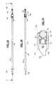
FIG. 1A illustrates a driver device having an articulating driver head;FIG. 1B illustrates a sectional view of the driver device along section line A-A ofFIG. 1A ;FIG. 1C illustrates a ball-in-socket joint of the driver devices ofFIG. 1A in greater detail;FIG. 2 illustrates a retention cap ofFIGS. 1A-1C ;FIGS. 3A-3B illustrate a spherical head ofFIGS. 1A-1C in greater detail;FIG. 3C illustrates a sectional view of the spherical head along section line A-A ofFIG. 3B ;FIG. 3D illustrates a sectional view of the spherical head along section line D-D ofFIG. 3A ;FIG. 4A illustrates an articulation housing assembly ofFIGS. 1A-1C in greater detail;FIG. 4B illustrates a sectional view of the articulation housing assembly along section line B-B ofFIG. 4A ;FIG. 4C illustrates a sectional view of the articulation housing assembly along section line A-A ofFIG. 4A ;FIGS. 5-8 illustrate an engagement of a screw with a driver device such as that shown inFIG. 1 ;FIGS. 9-12 illustrate an interaction of a stop region of a bushing of the driver device and an aiming device to provide disengagement of the screw from the driver device according to an embodiment;FIGS. 13-20 illustrate an interaction of a stop region of a bushing of the driver device and an aiming device to provide disengagement of the screw from the driver device in accordance with another embodiment;FIGS. 21-25 illustrate another embodiment of the driver device of the present disclosure;FIG. 26 illustrates another embodiment of the driver device of the present disclosure;FIGS. 27A-27C illustrate another embodiment of the articulating driver of the present disclosure;FIGS. 28A-28C illustrate a first spherical head of the embodiment ofFIGS. 27A-27C ;FIGS. 29A-29C illustrate a second spherical head of the embodiment ofFIGS. 27A-27C ;FIGS. 30A-30B illustrate the articulation housing assembly of the embodiment ofFIGS. 27A-27C in greater detail; andFIG. 31 illustrates a perspective view of the embodiment ofFIGS. 27A-27C .- With references to the FIGS., there is illustrated an articulating
driver 100 and a ball-in-socket joint 102. As will be described herein, the ball-in-socket joint 102 allows adriver tip 126 or other output shaft to articulate while transmitting input torque from aninput shaft 104 to thedriver tip 126. The input torque turns e.g., a screw or other component being driven by the articulatingdriver 100. The articulatingdriver 100 may be a jointed awl, screw driver or drill. - As shown in
FIGS. 1A-1C , the articulatingdriver 100 consists of theinput shaft 104 that, at afirst end 106, connects to a handle (not shown) and at asecond end 108 connects to anarticulation housing assembly 110 that forms an outer portion of the ball-in-socket joint 102. Theinput shaft 104 may be any type of shaft capable of transmitting input torque from the handle or a power tool to which theinput shaft 104 is attached. At thesecond end 108 of theinput shaft 104, acavity 114 is defined that accepts aspring 116 or the cavity walls are composed of a spring. One end of thespring 116 is received within thecavity 114, and the other end of thespring 116 is received within arecess 118 of aretention cap 120, which is shown in greater detail inFIG. 2 . As will be described later, thespring 116 provides positional retention of thedriver tip 126. Theretention cap 120 transmits force from thespring 116 to aspherical head 124 of thedriver tip 126 that is secured between theretention cap 120 and a taperedinner surface 130 of thearticulation housing assembly 110. As shown inFIG. 2 , adomed surface 122 may be defined at an end of theretention cap 120 opposite therecess 118 to receive thespherical head 124. - As shown in
FIG. 1C , thearticulation housing assembly 110 receives thesecond end 108 of theinput shaft 104, thespring 116, theretention cap 120, and thespherical head 124 of thedriver tip 126. As shown inFIG. 4 , thearticulation housing assembly 110 definesholes 136 within which pins134a,134band134care pressed. Thepins grooves FIGS. 3A-3D ). Through the cooperation of thepins grooves spherical head 124 transmits torque to an attachment that is received within a bushing132 (see,FIG. 1A ). Thebushing 132 provides positional retention of the attachment and may be made from Polyether ether ketone (PEEK) or an appropriate plastic or metal. - In accordance with aspects of the present disclosure, the
domed surface 122 of theretention cap 120 and the taperedinner surface 130 of thearticulation housing assembly 110 may each have a radius that is similar to, and designed to interface with thespherical head 124 head of thedriver tip 126. These radii allow thedriver tip 126 to articulate within thearticulation housing assembly 110, while retaining thespherical head 124 within thearticulation housing assembly 110. Thus, the interaction of thespring 116 pressing on theretention cap 120, which mates to thespherical head 124, and the taperedinner surface 130 of thearticulation housing assembly 110 serve to positionally retain thedriver tip 126 within thearticulation housing assembly 110. FIGS. 3A-3D illustrate thespherical head 124 and thedriver tip 126 in greater detail. As shown inFIG. 3A , thegrooves spherical head 124, and are wider near the diameter and taper moving toward the circumference. Thegrooves FIG. 3D ) withinspherical head 124. In some implementations, thegrooves FIG. 3C , the grooves may extend over an approximately 120° arc across the surface of thespherical head 124. Thus, it can be appreciated that the shape of thegrooves pins driver tip 126 with respect to theinput shaft 104 over a 360° rotation.- During assembly, the
input shaft 104 is pressed in thearticulation housing assembly 110 and cross-pinned to thearticulation housing assembly 110 using apin 112. Thepin 112 may be pressed-in and retained by an interference fit with theshaft 104; thepin 112 may be welded in place, or may be threaded into theshaft 104 or retained within a further sleeve used to preventpins 112,134a-134cfrom backing out. Other attachment mechanisms may be used in place of thepin 112. - The various components above may be made from stainless steel, titanium, titanium alloy, ceramic, etc. The
retention cap 120 may be fabricated from PEEK, stainless steel, polyethylene, or any metallic or polymetric material. Theretention cap 120 may also include a TiN coating to limit wear and galling on thespherical head 124. - In some implementations, the various components of the
driver 100 may have the following dimensions. The radius of curvature of thedomed surface 122 may be approximately 3.6 mm and may have a depth of 1.8 mm. Thespherical head 124 portion may have a diameter approximately 6.5 mm. Therecess 118 may have a depth of 1.5 mm to receive a portion of thespring 116. Theretention cap 120 may have a total height of 3.0 mm. The articulation housing assembly may have a length of 15 mm and the tapered inner surface may begin 1.6 mm from the edge of the housing assembly. The inner diameter of the articulation housing assembly may be 7.1 mm. The cavity defined in the second end of the input shaft may have a depth of 3.5 mm. - During operation, as the user rotates the
input shaft 104, torque is transmitted to thearticulation housing assembly 110 via the press-fit and thepin 112. This torque is then transmitted from thearticulation housing assembly 110 to the driver tip via action of thepins grooves spherical head 124 of thedriver tip 126. Thedriver tip 126 then transmits the torque to the attachment to turn, e.g., screws for insertion into bone. - Thus, the ball-in-
socket joint 102 of the present disclosure can be positioned stabily in a multi-angle screwing/unscrewing operation. In particular, because the ball-in-socket joint 102 provides for approximately 45-50° of angulation, thedriver 100 maintains thedriver tip 126 within a useful range of operation. - Referring now to
FIGS. 5-8 , the engagement of a screw with the articulatingdriver 100 will be described. As shown in detail in exploded view ofFIG. 5 , abushing 232 includesinner threads 506 disposed at a distal end thereof andinner threads 508 disposed at the proximal end thereof. The diameter of theinner threads 506 andinner threads 508 have a dimension that is complementary with an outer threadedportion 514 of thescrew 502 and a threadedregion 510 of thedriver tip 126, respectively. The pitches of theinner threads 506 and outer threadedportion 514, andinner threads 508 and a threadedregion 510 may be respectively optimized to match. The outer threadedportion 514 may be a conical thread or a straight thread. In some implementations, the diameter of theinner threads 506 may be larger than theinner threads 508 to allow theinner threads 506 to pass over the threadedregion 510, as will be described below. In some implementations, the diameter of theinner threads 506 and theouter threads 508 may be the same. - The bushing further includes a
stop region 516, which cooperates with an aiming device or guide to halt forward progress of thebushing 232 within the aiming device when thescrew 502 is driven by the articulatingdriver 100. Further details of the interaction of thestop region 516 and the aiming device will be described below with reference toFIGS. 9-12 . Also as shown, thedriver tip 126 includes at a distal end thereof ascrew interface 512 that is adapted to engage a complementary recess defined within the head thescrew 502. Thescrew interface 512 and complementary recess may be star-shaped, hexagonal, square, a polygonal shape, etc. - The operational engagement of the
bushing 232, thedriver tip 126 and thescrew 502 will now be described.FIG. 5 illustrates the components in a separated state, where initially, thebushing 232 is placed over thescrew interface 512 to engage theinner threads 508 with the threadedregion 510. Thebushing 232 is rotated in, e.g., a clockwise direction such that theinner threads 508 mesh with the threadedregion 510 to advance the bushing in the proximal direction. As shown inFIG. 6 , thebushing 232 may be moved in the proximal direction such that theinner threads 506 pass over the threadedregion 510, as the diameter of theinner threads 506 may be larger than the threadedregion 510. In implementations where the diameter of theinner threads 506 is equal toinner threads 508, the inner threads may engage the threadedregion 510. As such, an intermediate state of engagement is achieved (shown inFIG. 6 ) where thescrew interface 512 and a portion of the threadedregion 510 protrude through the distal end of thebushing 232. Thus, thescrew interface 512 is positioned such that it can be received within a complementary recess in the head of thescrew 502. - Next, as shown in
FIG. 7 , thescrew 502 is brought into proximity with thescrew interface 512 such that the interface may engage the head of thescrew 502. An operator may then rotate thebushing 232 in e.g., the counterclockwise direction to cause theinner threads 508 to mesh with the threadedregion 510, thus moving thebushing 232 in the distal direction. - As shown in fully engaged view of
FIG. 8 , thebushing 232 is moved distally until theinner threads 506 engage the threadedportion 514 of thescrew 502. The engagement of theinner threads 506 and the threadedportion 514 serves to retain thescrew 502 within thebushing 232. Thus,FIG. 8 illustrates thescrew 502 when loaded into the articulatingdriver 100 and ready to be driven into an associated plate or portion of bone. - With reference to
FIGS. 9-12 , the operation of the articulatingdriver 100 to drive thescrew 502 into an associated plate or portion of bone will now be described. As shown inFIGS. 9-12 , an aiming device or guide600 may be used to guide thescrew 502. The aimingdevice 600 includes a plurality of aimingholes 604, each having apin 602 that protrudes through an inner wall thereof at a distal end. An operator may drive thescrew 502 into, e.g., bone, by inserting thescrew 502 into an appropriate one of the aiming holes604. Thescrew 502 will pass through the aiminghole 604 and out of the aimingdevice 600. However, the aimingdevice 600 is sized such that thebushing 232 remains rotably positioned within a proximal portion of the aiming hole604 (see, e.g.,FIG. 10 ). As the operator drives thescrew 502 using thedriver 100, thescrew 502 andbushing 232 will rotate and move distally within the aiminghole 604 as thescrew 502 engages the plate or bone. - As shown in
FIG. 11 , the distal movement will cause thestop region 516 of thebushing 232 to engage thepin 602. As illustrated inFIGS. 5 and 11 , thestop region 516 may be formed having a jagged or zig-zag edge, such that thepin 602 is caught within a vertex516aformed by the edge. Engagement of thestop region 516 with thepin 602 will cause thebushing 232 to cease rotational and longitudinal movement (i.e., it will be stopped within the aiming hole604). It is noted that other designs may be used to stop the advancement of thebushing 232 within the aiming hole604 (e.g., frictional engagement). - After the
bushing 232 is stopped, the application of torque to thedriver tip 126 will continue to rotate thescrew 502 within thebushing 232. Thus, thescrew 502 will continue to be driven in the distal direction along the longitudinal axis of thedriver tip 126. As shown inFIG. 12 , continuing to drive thescrew 502 will rotate the threadedregion 514 within theinner threads 506, causing the threadedregion 514 to progress out of the distal end of thebushing 232. As such, thescrew 502 advances from thebushing 232 and will be released from thedriver 100. Operation of the articulatingdriver 100 may continue in order to drive thescrew 502 into its final position through the continued engagement of thescrew interface 512 with the head of thescrew 502. Once thescrew 502 reaches its final position, the articulatingdriver 100 may be withdrawn from the aiming device or guide600. - Referring now to
FIGS. 13-20 , the engagement of a screw with the articulatingdriver 100 will be described in accordance with another implementation. Many of the details of the articulatingdriver 100 of this implementation are the same as the that described with reference toFIGS. 1-12 ; however, as shown in detail inFIGS. 13 and 14 , abushing 732 includes inner threads706 (FIG. 14 ) disposed at a distal end thereof andinner threads 708 disposed at the proximal end thereof. The diameter of theinner threads 706 andinner threads 708 have a dimension that is complementary with an outer threadedportion 514 of thescrew 502 and a threadedregion 510 of thedriver tip 126, respectively. The pitches of theinner threads 706 and outer threadedportion 514, andinner threads 708 and a threadedregion 510 may be respectively optimized to match. The outer threadedportion 514 may be a conical thread or a straight thread. In some implementations, the diameter of theinner threads 706 may be larger than theinner threads 708 to allow theinner threads 706 to pass over the threadedregion 510, as will be described below. In some implementations, the diameter of theinner threads 706 and theouter threads 708 may be the same. - The
bushing 732 further includeslobes 734, which cooperate with an aiming device or guide to halt forward progress of thebushing 732 within the aiming device when thescrew 502 is driven by the articulatingdriver 100. The cooperation of thelobes 734 with the aiming device is described below in more detail with reference toFIGS. 17-20 . Thelobes 734 may be formed such that they extend outwardly from the circumference of thebushing 732. Three or fourlobes 734 may be provided at the proximal end of thebushing 732; however any number of lobes may be provided. - The operational engagement of the
bushing 732, thedriver tip 126 and thescrew 502 will now be described.FIG. 14 illustrates the components in a separated state, where initially, thebushing 732 is placed over thescrew interface 512 to engage theinner threads 508 with the threadedregion 510. Thebushing 732 is rotated in, e.g., a clockwise direction such that theinner threads 508 mesh with the threadedregion 510 to advance the bushing in the proximal direction. As shown inFIG. 15 , thebushing 732 may be moved in the proximal direction such that theinner threads 506 pass over the threadedregion 510, as the diameter of theinner threads 506 may be larger than the threadedregion 510. In implementations where the diameter of theinner threads 506 is equal toinner threads 508, the inner threads may engage the threadedregion 510. As such, an intermediate state of engagement is achieved (shown inFIG. 15 ) where thescrew interface 512 and a portion of the threadedregion 510 protrude through the distal end of thebushing 232. Thus, thescrew interface 512 is positioned such that it can be received within a complementary recess in the head of thescrew 502. - Next, as shown in fully engaged view of
FIG. 16 , thebushing 732 is moved distally until theinner threads 506 engage the threadedportion 514 of thescrew 502. The engagement of theinner threads 506 and the threadedportion 514 serves to retain thescrew 502 within thebushing 732. Thus,FIG. 16 illustrates thescrew 502 when loaded into the articulatingdriver 100 and ready to be driven into an associated plate or portion of bone. - With reference to
FIGS. 17-20 , the operation of the articulatingdriver 100 to drive thescrew 502 into an associated plate or portion of bone will now be described. As shown inFIGS. 17-20 , an aiming device or guide800 may be used to guide thescrew 502. The aimingdevice 800 includes a plurality of aimingholes 804, each having circumferential lobes802 at a proximal end. The circumferential lobes802 may extend inwardly from a center of each aiminghole 804 and receive thelobes 734 of thebushing 732. An operator may drive thescrew 502 into, e.g., bone, by inserting thescrew 502 into an appropriate one of the aiming holes804. Thescrew 502 will pass through the aiminghole 804 and out of the aimingdevice 800. However, the aimingdevice 800 is sized such that thebushing 732 remains rotably positioned within a proximal portion of the aiming hole804 (see, e.g.,FIG. 18 ). As the operator drives thescrew 502 using thedriver 100, thescrew 502 andbushing 732 will rotate and move distally within the aiminghole 804 as thescrew 502 engages the plate or bone. - As shown in
FIG. 19 , the distal movement will cause thelobes 734 of thebushing 732 to be received within the lobes802. As illustrated inFIGS. 13 and 17 , thelobes 734 and the lobes802 may be formed having complementary shapes such that thelobes 734 are received with the complementary shaped lobes802. Engagement of thelobes 734 and lobes802 will cause thebushing 732 to cease rotational and longitudinal movement (i.e., it will be stopped within the aiming hole804). - After the
bushing 732 is stopped, the application of torque to thedriver tip 126 will continue to rotate thescrew 502 within thebushing 732. Thus, thescrew 502 will continue to be driving in the distal direction along the longitudinal axis of thedriver 100. As shown inFIG. 20 , continuing to drive thescrew 502 will rotate the threadedregion 514 within theinner threads 506, causing the threadedregion 514 to progress out of the distal end of thebushing 732. As such, thescrew 502 advances from thebushing 732 and will be released from thedriver 100. Operation of the articulatingdriver 100 may continue in order to drive thescrew 502 into its final position through the continued engagement of thescrew interface 512 with the head of thescrew 502. Once thescrew 502 reaches its final position, the articulatingdriver 100 may be withdrawn from the aiming device or guide800. FIGS. 21-25 illustrate another embodiment of an articulating driver1300 of the present disclosure. As shown, the articulating driver1300 may include three components, a central screwdriver (FIG. 21 ), a central sleeve (FIG. 22 ) and an outer, slip sleeve (FIG. 23 ). Thecentral screwdriver 1301 may be a straight or jointed driver. As illustrated inFIGS. 24A and 24B , the central screwdriver may be a jointed driver which is composed of aproximal shaft 1301 which has aninterface 1301athat is adapted to provide a connection to, e.g., a handle for applying torque. The central screwdriver may include a jointed feature (e.g., a universal joint1308) and a distal portion containing thescrew interface 1306a(e.g., a self retaining star-drive). Alternatively, thejoint mechanism 1308 may accomplished by beam coupling, spring coupling, jaw coupling, etc. Alternatively, thescrew interface 1306amay have a hexagonal, square, polygonal shape, etc. The central screwdriver may include adistal tip 1306 that at a proximal end thereof, includes acircumferential groove 1313 to allow for retention of the central sleeve.- Referring now to
FIG. 22 , the central sleeve may include amechanism 1302 to retain the central sleeve on the central screwdriver ofFIG. 21 . For example, themechanism 1302 may be a spring-loaded quick coupling with detents for retention on the circumferential groove of the central screwdriver. Between the proximal end and the distal tip, there is ahelical structure 1304 that may be provided to allow for bending of the jointedsegment 1308 when the central sleeve is assembled. The nature of the helical structure1034 allows it to act as a spring and hence bend with thejoint segment 1038. Thehelical structure 1304 may be manufactured from a single solid tube with the central sleeve or may be bonded to the proximal and distal portion as a separate element. The later alternative would enable the use of any material that would be appropriate for thehelical structure 1304. Such materials could be, but are not limited to, Nitinol, spring steel, certain grades of stainless steel or any other material which offers appropriate elasticity/memory. An additional benefit of thehelical structure 1304 and its associated memory is that it prevents the loosening of jointed instruments, which is often encountered when there is repeated use of jointed instruments with universal joints. - At the distal tip of the central sleeve, a
distal portion 1305 is providing having an outer diameter and length so as to have an appropriate interface with an aiming device or guide (e.g.,600) which may be used in association with the driver. An internal thread at the distal tip1309 (FIG. 25 ) may engage the screw which would have to have either a straight or conical thread on the external surface of its head. The pitch of this internal thread would be optimized to match that of the thread on the screw. - To assemble the screw to the driver, the
screw interface 1306amay protrude slightly out of the tip of the central sleeve. The screw would engage thescrew interface 1306aof the driver, which may be a self-retaining interface. Then, using the retention mechanism1032 of the central sleeve to act also as a turning knob, the central sleeve is turned such that theinternal thread 1309 engages the external thread of the screw head. In turning this central sleeve, one or both of the following may occur, the screw is pulled further onto thescrew driver interface 1306aor thehelical structure 1304 elongates as theinternal thread advances 1309 over the screw head. The screw is then rigidly fixed to the screwdriver via the threaded connection to the central sleeve and the connection of the central sleeve to the central driver. The screw is also connected to the central driver via thescrew interface 1306awhich allows for torque transmission and screw placement. - As the operator advances the screw, there may be a tendency to hold the length of the driver for guidance. If this holding occurs on the central sleeve, it may result in early disengagement of the screw from the central sleeve as the central sleeve would remain stationary relative to a rotating screw driver and screw. In order to prevent this from occurring, an
outer slip sleeve 1311 may be positioned on the outside of the central sleeve. Thisslip sleeve 1311 may freely rotate about the central sleeve due to a nonrigid connection 1310. Thisconnection 1310 allows for rotation, but restricts translation. In addition, at the distal end of the slip sleeve, there is located a flexibleplastic sleeve 1312 that covers the helical portion from entangling surrounding tissue. - As the screw nears its final position, the thread on its head engages an associated plate or portion of bone. However, in the insertion position, this head is covered by the central sleeve. Here, the user knows when to disengage the central sleeve. An alternative method involves the placement of
toothed features 1307 on the distal portion of the central sleeve, which when approaching the final position, will engage into a counter-feature or the bone and will result in fixing the central sleeve from rotating with the central driver. Further rotation of the central driver will result in automatic disengagement of the screw from the central sleeve. The helical structure will allow the central sleeve can collapse with the advancement while the screwdriver-screw interface remains for optimum torque transmission. Once, the screw has been tightened into place, it will be no longer be connected to the driver itself and the driver is free to be removed. - In some implementations, in order to prevent deformation of the helical structure through over tightening of the central sleeve onto the screw, the helical structure may spiral in the opposite direction of the thread (i.e., counter-clockwise helical structure is provided for a clockwise thread). Therefore, over tightening will result in the helical structure collapsing onto the inner screwdriver and hence preventing it from deforming outward.
FIG. 26 illustrates another embodiment that uses an external thread on the central sleeve which would mate to a corresponding internal thread on the screw. Such a configuration may be used with variable angle screws or pedicle screws, and screws with locking threads.- In yet another embodiment, the design of
FIGS. 21-25 may omit thetoothed feature 1307. Turning of the screw with the head covered will result in engagement of the central sleeve onto the aiming device. Subsequent turning of the screw after this condition is achieved will result in lagging of the plate to the bone into which the screw is purchased or vice-versa. FIGS. 27-31 illustrate another embodiment of a joint2702 of the articulating driver of the present disclosure. As shown inFIGS. 27A-27C , the articulating driver2700 consists of aninput shaft 2704 that, at afirst end 2706, connects to a handle (not shown) and has a firstspherical head 2708. The firstspherical head 2708 is secured within anarticulation housing assembly 2710 by afirst pin 2712 that passes through acavity 2709. Theinput shaft 2704 may be any type of shaft capable of transmitting input torque from the handle or a power tool to which theinput shaft 2704 is attached. A secondspherical head 2724 is formed at a proximal end of adriver tip 2726 and is secured to thearticulation housing assembly 2710 by asecond pin 2734 that passes through a cavity2729. When secured within thearticulation housing assembly 2710, aball 2718 formed at the distal end of the firstspherical head 2708 is received within asocket 2722 that is defined within a proximal end of the secondspherical head 2724, the interaction of the various components is described further with reference toFIG. 31 .- As shown in
FIG. 27C , enclosed within thearticulation housing assembly 2710 is the firstspherical head 2708 of theinput shaft 2704, afirst washer 2712, aspring 2716, asecond washer 2720, andspherical head 2724 of thedriver tip 2726. Thespring 2716 is disposed between a first washer2714 and asecond washer 2720. The first washer2714 has a tapered edge that abuts the firstspherical head 2708 and thesecond washer 2720 has a tapered edge that abuts the secondspherical head 2734. Thespring 2716 exerts an expansion force on both the first washer2714 and thesecond washer 2720 to frictionally positionally retain the firstspherical head 2708 and the secondspherical head 2734 within the housing assembly2710 a user-set angulation. The proximal and distal openings of thearticulation housing assembly 2710 each have a chamferededge first base 2705 and a second base2727 to act as a stop to limit the total angulation of the joint2702, as described below. FIGS. 28A-28C illustrate the firstspherical head 2708 in greater detail. As shown inFIG. 28A , thecavity 2709 forms a generallyovular opening 2717 on a surface of the fist spherical head2708 (a bottom opening is not shown in the FIGS.). In some implementations, thecavity 2709 may be milled into firstspherical head 2708 having a generally “bow-tie” shape. As shown in the cross-sectional view ofFIG. 28C , thecavity 2709 may be formed such theopening 2717 extends having an approximately 22° arc in each direction with respect to a center axis of the cavity2709 (providing a total arc of approximately 44° across the surface of the first spherical head2708). The “bow-tie” shaped of thecavity 2709 enables the firstspherical head 2708 to be angulated with respect to thefirst pin 2712 passing therethrough, which can be appreciated is positioned along the center axis of thecavity 2709 shown inFIG. 28C when the firstspherical head 2708 is assembled into the joint2702.FIGS. 29A-29C illustrate the secondspherical head 2724 in greater detail. As shown inFIG. 29A , thecavity 2725 forms a generallyovular opening 2728 on the surface of the second spherical head2724 (a bottom opening is not shown of the FIGS.). In some implementations, thecavity 2725 may be milled into secondspherical head 2724 having a “bow-tie” shape similar to thecavity 2709. As shown in the cross-sectional view ofFIG. 29C , thecavity 2725 may be formed such theopening 2728 extends in a 22° arc in each direction with respect to a center axis of thecavity 2725. Thus, similar to thecavity 2709, the “bow-tie” shapedcavity 2725 enables the secondspherical head 2724 to be angulated with respect to thesecond pin 2734, which can be appreciated is positioned along the center axis of thecavity 2725 shown inFIG. 29C when the second spherical head is assembled into the joint2702.- As shown in
FIG. 30A-30B , thearticulation housing assembly 2710 definesholes 2736 into which thefirst pin 2712 and thesecond pin 2734 may be pressed.Openings 2740 are provided to enable easy cleaning of the interior of the articulatinghousing assembly 2710.FIG. 30B illustrates the chamferededges articulation housing assembly 2710. Each edge may be formed having approximately a 20° angle with respect to the longitudinal axis of thearticulation housing assembly 2710. The chamfered edges2711 and2730 may abut thefirst base 2705 and the second base2727 to limit the total angulation at approximately 40°. FIG. 31 illustrates a perspective view of the assembled joint1702. To assemble the joint1702, theinput shaft 2704 is inserted into thearticulation housing assembly 2710 and pinned to thearticulation housing assembly 2710 by thefirst pin 2712. Thefirst washer 2712, thespring 2716 and thesecond washer 2720 are then placed within thearticulation housing assembly 2710. Thedriver tip 2726 is inserted into thearticulation housing assembly 2710 and pinned by thesecond pin 2734. Thepins housing 2710; thepins housing 2710. Other attachment mechanisms may be used in place of thepins - The various components above may be made from stainless steel, titanium, titanium alloy, ceramic, etc. The
first washer 2712 and thesecond washer 2720 may be made from PEEK. Thespring 2716 may be any spring having a spring constant to exert a sufficient force on thefirst washer 2712 and thesecond washer 2720 to provide the aforementioned positional retention of the firstspherical head 2708 and the secondspherical head 2724 within the articulatinghousing 2710. - During use, a user can initially position the
input shaft 2704 and thedriver tip 2726 by angulating theinput shaft 2704 and thedriver tip 2726 to a desired total angulation. The approximately 22° of angulation of the firstspherical head 2708 and the approximately 22° of angulation of the secondspherical head 2724 may provide for a total angulation of approximately 44° of thedriver tip 2726 with respect to theinput shaft 2704. However, as noted above, the total angulation may be limited to approximately 40° by the interaction of the chamferededges first base 2705 and the second base2727. The angulation may be maintained throughout a 360° rotation of theinput shaft 2704 anddriver tip 2726 by the positional retention provided by the interaction of thespring 2716, the first washer2714 and thesecond washer 2720 and the constant velocity provided by theball 2718 and thesocket 2722. - As the user rotates the
input shaft 2704, torque is transmitted to thearticulation housing assembly 2710 via the interaction of thefirst pin 2712 within thecavity 2709 of the firstspherical head 2708. This torque is then transmitted from thearticulation housing assembly 2710 to the driver tip via action of thesecond pin 2734 within thecavity 2725 of the secondspherical head 2724 of thedriver tip 2726. Thedriver tip 2726 then transmits the torque to the attachment to turn, e.g., screws for insertion into bone. - Although the subject matter has been described in language specific to structural features and/or methodological acts, it is to be understood that the subject matter defined in the appended claims is not necessarily limited to the specific features or acts described above. Rather, the specific features and acts described above are disclosed as example forms of implementing the claims.
Claims (30)
Priority Applications (6)
| Application Number | Priority Date | Filing Date | Title |
|---|---|---|---|
| US13/547,540US20140018816A1 (en) | 2012-07-12 | 2012-07-12 | Torque transmitting ball joint driver having a rigid fixation mechanism |
| EP13740171.7AEP2872060B1 (en) | 2012-07-12 | 2013-07-12 | Torque transmitting ball joint driver having a rigid fixation mechanism |
| PCT/US2013/050338WO2014012035A2 (en) | 2012-07-12 | 2013-07-12 | Torque transmitting ball joint driver having a rigid fixation mechanism |
| US16/207,823US11331106B2 (en) | 2012-07-12 | 2018-12-03 | Torque transmitting ball joint driver having a rigid fixation mechanism |
| US17/743,925US12004754B2 (en) | 2012-07-12 | 2022-05-13 | Torque transmitting ball joint driver having a rigid fixation mechanism |
| US18/669,913US20240299043A1 (en) | 2012-07-12 | 2024-05-21 | Torque transmitting ball joint driver having a rigid fixation mechanism |
Applications Claiming Priority (1)
| Application Number | Priority Date | Filing Date | Title |
|---|---|---|---|
| US13/547,540US20140018816A1 (en) | 2012-07-12 | 2012-07-12 | Torque transmitting ball joint driver having a rigid fixation mechanism |
Related Child Applications (1)
| Application Number | Title | Priority Date | Filing Date |
|---|---|---|---|
| US16/207,823ContinuationUS11331106B2 (en) | 2012-07-12 | 2018-12-03 | Torque transmitting ball joint driver having a rigid fixation mechanism |
Publications (1)
| Publication Number | Publication Date |
|---|---|
| US20140018816A1true US20140018816A1 (en) | 2014-01-16 |
Family
ID=48857012
Family Applications (4)
| Application Number | Title | Priority Date | Filing Date |
|---|---|---|---|
| US13/547,540AbandonedUS20140018816A1 (en) | 2012-07-12 | 2012-07-12 | Torque transmitting ball joint driver having a rigid fixation mechanism |
| US16/207,823Active2032-08-03US11331106B2 (en) | 2012-07-12 | 2018-12-03 | Torque transmitting ball joint driver having a rigid fixation mechanism |
| US17/743,925Active2032-10-11US12004754B2 (en) | 2012-07-12 | 2022-05-13 | Torque transmitting ball joint driver having a rigid fixation mechanism |
| US18/669,913PendingUS20240299043A1 (en) | 2012-07-12 | 2024-05-21 | Torque transmitting ball joint driver having a rigid fixation mechanism |
Family Applications After (3)
| Application Number | Title | Priority Date | Filing Date |
|---|---|---|---|
| US16/207,823Active2032-08-03US11331106B2 (en) | 2012-07-12 | 2018-12-03 | Torque transmitting ball joint driver having a rigid fixation mechanism |
| US17/743,925Active2032-10-11US12004754B2 (en) | 2012-07-12 | 2022-05-13 | Torque transmitting ball joint driver having a rigid fixation mechanism |
| US18/669,913PendingUS20240299043A1 (en) | 2012-07-12 | 2024-05-21 | Torque transmitting ball joint driver having a rigid fixation mechanism |
Country Status (3)
| Country | Link |
|---|---|
| US (4) | US20140018816A1 (en) |
| EP (1) | EP2872060B1 (en) |
| WO (1) | WO2014012035A2 (en) |
Cited By (65)
| Publication number | Priority date | Publication date | Assignee | Title |
|---|---|---|---|---|
| US20130150906A1 (en)* | 2011-12-13 | 2013-06-13 | Symmetry Medical, Inc | System and method for a lockable polyaxial driver tool |
| US20150282855A1 (en)* | 2014-04-04 | 2015-10-08 | K2M, Inc. | Screw insertion instrument |
| DE102014114644A1 (en)* | 2014-10-09 | 2016-04-14 | Aesculap Ag | Medical screwdriver, adapter and cannula for the medical screwdriver |
| US20170113024A1 (en)* | 2015-10-27 | 2017-04-27 | Spinal Simplicity, Llc | Flexible guide wire with tantalum marker |
| US20180161171A1 (en)* | 2016-12-14 | 2018-06-14 | DePuy Synthes Products, Inc. | Intervertebral implant inserter and related methods |
| US20180325574A1 (en)* | 2017-03-31 | 2018-11-15 | Spineology Inc. | Swivel drive system for screw insertion |
| US10646261B2 (en)* | 2018-07-24 | 2020-05-12 | Warsaw Orthopedic, Inc. | Multi-purpose screwdriver and method of use |
| IT201800020350A1 (en)* | 2018-12-20 | 2020-06-20 | Medacta Int Sa | SURGICAL SCREWDRIVER |
| IT201800020290A1 (en)* | 2018-12-20 | 2020-06-20 | Medacta Int Sa | SURGICAL SCREWDRIVER |
| US20200345340A1 (en)* | 2012-08-03 | 2020-11-05 | Howmedica Osteonics Corp. | Soft Tissue Fixation Device And Methods |
| WO2020236229A1 (en)* | 2019-05-22 | 2020-11-26 | Spinal Elements, Inc. | Bone tie and bone tie inserter |
| US10940016B2 (en) | 2017-07-05 | 2021-03-09 | Medos International Sarl | Expandable intervertebral fusion cage |
| USD926982S1 (en) | 2011-10-26 | 2021-08-03 | Spinal Elements, Inc. | Interbody bone implant |
| US11083497B2 (en)* | 2015-08-10 | 2021-08-10 | Stryker European Operations Holdings Llc | Adjustment instrument with tactile feedback |
| US11090068B2 (en)* | 2018-11-08 | 2021-08-17 | Ctl Medical Corporation | Vertebral body reaming method |
| US11207103B2 (en) | 2014-10-24 | 2021-12-28 | Stryker European Operations Holdings Llc | Methods and systems for adjusting an external fixation frame |
| US11272961B2 (en) | 2013-03-14 | 2022-03-15 | Spinal Elements, Inc. | Apparatus for bone stabilization and distraction and methods of use |
| US11291477B1 (en) | 2021-05-04 | 2022-04-05 | Warsaw Orthopedic, Inc. | Dorsal adjusting implant and methods of use |
| US11298147B2 (en)* | 2017-03-03 | 2022-04-12 | Industrial Technology Research Institute | Minimally invasive surgical device |
| US11304733B2 (en) | 2020-02-14 | 2022-04-19 | Spinal Elements, Inc. | Bone tie methods |
| US20220133503A1 (en)* | 2020-11-05 | 2022-05-05 | Warsaw Orthopedic, Inc. | Surgery instruments with a movable handle |
| US11344424B2 (en) | 2017-06-14 | 2022-05-31 | Medos International Sarl | Expandable intervertebral implant and related methods |
| US11426290B2 (en) | 2015-03-06 | 2022-08-30 | DePuy Synthes Products, Inc. | Expandable intervertebral implant, system, kit and method |
| US11426286B2 (en) | 2020-03-06 | 2022-08-30 | Eit Emerging Implant Technologies Gmbh | Expandable intervertebral implant |
| US11432848B1 (en) | 2021-05-12 | 2022-09-06 | Warsaw Orthopedic, Inc. | Top loading quick lock construct |
| US11446155B2 (en) | 2017-05-08 | 2022-09-20 | Medos International Sarl | Expandable cage |
| US11446156B2 (en) | 2018-10-25 | 2022-09-20 | Medos International Sarl | Expandable intervertebral implant, inserter instrument, and related methods |
| US11457959B2 (en) | 2019-05-22 | 2022-10-04 | Spinal Elements, Inc. | Bone tie and bone tie inserter |
| US11464551B2 (en) | 2011-02-24 | 2022-10-11 | Spinal Elements, Inc. | Methods and apparatus for stabilizing bone |
| US11478275B2 (en) | 2014-09-17 | 2022-10-25 | Spinal Elements, Inc. | Flexible fastening band connector |
| US11497619B2 (en) | 2013-03-07 | 2022-11-15 | DePuy Synthes Products, Inc. | Intervertebral implant |
| US11510788B2 (en) | 2016-06-28 | 2022-11-29 | Eit Emerging Implant Technologies Gmbh | Expandable, angularly adjustable intervertebral cages |
| US11517363B2 (en) | 2020-11-05 | 2022-12-06 | Warsaw Orthopedic, Inc. | Screw driver and complimentary screws |
| US11517354B2 (en) | 2013-09-27 | 2022-12-06 | Spinal Elements, Inc. | Method of placing an implant between bone portions |
| US11596523B2 (en) | 2016-06-28 | 2023-03-07 | Eit Emerging Implant Technologies Gmbh | Expandable and angularly adjustable articulating intervertebral cages |
| US11612499B2 (en) | 2021-06-24 | 2023-03-28 | Warsaw Orthopedic, Inc. | Expandable interbody implant |
| US11617655B2 (en) | 2008-04-05 | 2023-04-04 | DePuy Synthes Products, Inc. | Expandable intervertebral implant |
| US11622868B2 (en) | 2007-06-26 | 2023-04-11 | DePuy Synthes Products, Inc. | Highly lordosed fusion cage |
| US11627998B2 (en) | 2020-12-11 | 2023-04-18 | Warsaw Orthopedic, Inc. | Head position and driver combination instrument |
| US11654033B2 (en) | 2010-06-29 | 2023-05-23 | DePuy Synthes Products, Inc. | Distractible intervertebral implant |
| CN116172652A (en)* | 2023-01-19 | 2023-05-30 | 北京德尔康尼骨科医院有限公司 | Microfracture Instruments |
| WO2023079176A3 (en)* | 2021-11-08 | 2023-06-15 | Medos International Sarl | Bone screw inserters |
| US11712270B2 (en) | 2021-05-17 | 2023-08-01 | Warsaw Orthopedic, Inc. | Quick lock clamp constructs and associated methods |
| US20230263641A1 (en)* | 2016-08-19 | 2023-08-24 | DePuy Synthes Products, Inc. | Inserter guide and driver system |
| US11752009B2 (en) | 2021-04-06 | 2023-09-12 | Medos International Sarl | Expandable intervertebral fusion cage |
| US11806250B2 (en) | 2018-02-22 | 2023-11-07 | Warsaw Orthopedic, Inc. | Expandable spinal implant system and method of using same |
| US11833059B2 (en) | 2020-11-05 | 2023-12-05 | Warsaw Orthopedic, Inc. | Expandable inter-body device, expandable plate system, and associated methods |
| US11850160B2 (en) | 2021-03-26 | 2023-12-26 | Medos International Sarl | Expandable lordotic intervertebral fusion cage |
| US11872139B2 (en) | 2010-06-24 | 2024-01-16 | DePuy Synthes Products, Inc. | Enhanced cage insertion assembly |
| US11918258B2 (en) | 2013-09-27 | 2024-03-05 | Spinal Elements, Inc. | Device and method for reinforcement of a facet |
| US11957391B2 (en) | 2021-11-01 | 2024-04-16 | Warsaw Orthopedic, Inc. | Bone screw having an overmold of a shank |
| US11963881B2 (en) | 2020-11-05 | 2024-04-23 | Warsaw Orthopedic, Inc. | Expandable inter-body device, system, and method |
| USRE49973E1 (en) | 2013-02-28 | 2024-05-21 | DePuy Synthes Products, Inc. | Expandable intervertebral implant, system, kit and method |
| US12004782B2 (en) | 2020-03-26 | 2024-06-11 | Warsaw Orthopedic, Inc. | Instrument for locking orthopedic screws |
| US12090064B2 (en) | 2022-03-01 | 2024-09-17 | Medos International Sarl | Stabilization members for expandable intervertebral implants, and related systems and methods |
| US12097124B2 (en) | 2009-03-30 | 2024-09-24 | DePuy Synthes Products, Inc. | Zero profile spinal fusion cage |
| US12121453B2 (en) | 2020-11-05 | 2024-10-22 | Warsaw Orthopedic, Inc. | Dual wedge expandable implant with eyelets, system, and method of use |
| US12171439B2 (en) | 2020-11-05 | 2024-12-24 | Warsaw Orthopedic, Inc. | Protected drill |
| US12239544B2 (en) | 2020-11-05 | 2025-03-04 | Warsaw Orthopedic, Inc. | Rhomboid shaped implants |
| US20250102019A1 (en)* | 2019-01-25 | 2025-03-27 | Encore Medical, L.P. (D/B/A Djo Surgical) | Universal joint assembly |
| US12295865B2 (en) | 2021-06-24 | 2025-05-13 | Warsaw Orthopedic, Inc. | Expandable interbody implant and corresponding inserter |
| US12318308B2 (en) | 2020-11-05 | 2025-06-03 | Warsaw Orthopedic, Inc. | Dual expandable inter-body device |
| US12369952B2 (en) | 2021-12-10 | 2025-07-29 | Spinal Elements, Inc. | Bone tie and portal |
| US12414863B2 (en) | 2021-06-24 | 2025-09-16 | Warsaw Orthopedic, Inc. | Expandable interbody implant and corresponding surgical tool |
| US12440242B2 (en) | 2024-04-29 | 2025-10-14 | Spinal Elements, Inc. | Flexible fastening band connector |
Families Citing this family (2)
| Publication number | Priority date | Publication date | Assignee | Title |
|---|---|---|---|---|
| US10660687B2 (en) | 2017-06-30 | 2020-05-26 | A&E Advanced Closure Systems, Llc | Driver tool and method |
| US11871925B2 (en)* | 2020-07-28 | 2024-01-16 | Cilag Gmbh International | Surgical instruments with dual spherical articulation joint arrangements |
Citations (11)
| Publication number | Priority date | Publication date | Assignee | Title |
|---|---|---|---|---|
| US4736658A (en)* | 1985-12-13 | 1988-04-12 | Jore Matthew B | Screw holding and driving device |
| US5797918A (en)* | 1991-12-13 | 1998-08-25 | David A. McGuire | Flexible surgical screwdriver and methods of arthroscopic ligament reconstruction |
| US6193721B1 (en)* | 1997-02-11 | 2001-02-27 | Gary K. Michelson | Multi-lock anterior cervical plating system |
| US20040267275A1 (en)* | 2003-06-26 | 2004-12-30 | Cournoyer John R. | Spinal implant holder and rod reduction systems and methods |
| US20050038432A1 (en)* | 2003-04-25 | 2005-02-17 | Shaolian Samuel M. | Articulating spinal fixation rod and system |
| US20060079903A1 (en)* | 2004-10-08 | 2006-04-13 | Wong David A | Minimally invasive pedicle screw and guide support |
| US20060200139A1 (en)* | 1988-06-13 | 2006-09-07 | Sdgi Holdings, Inc. | Tissue dilator and method for performing a spinal procedure |
| US20080140086A1 (en)* | 2006-12-07 | 2008-06-12 | Jesse Gabriel Moore | Gravity feed implant dispenser |
| US20080215061A1 (en)* | 2005-09-09 | 2008-09-04 | Aesculap Ag & Co. Kg | Screwdriver for bone screws |
| US20080243190A1 (en)* | 2007-03-29 | 2008-10-02 | Depuy Spine, Inc. | In-line rod reduction device and methods |
| US20110197719A1 (en)* | 2010-02-16 | 2011-08-18 | Neitzell Roger D | Driver accessory |
Family Cites Families (18)
| Publication number | Priority date | Publication date | Assignee | Title |
|---|---|---|---|---|
| US61581A (en) | 1867-01-29 | -taylor | ||
| US2526100A (en) | 1946-05-29 | 1950-10-17 | Kalamazoo Sled Company | Hand sled |
| US2526105A (en) | 1947-01-13 | 1950-10-17 | James B Adams | Universal joint for hand tools |
| US4065941A (en)* | 1975-05-16 | 1978-01-03 | Koto Sangyo Kabushiki Kaisha | Universal joint |
| US4636180A (en) | 1984-08-23 | 1987-01-13 | Allied Corporation | Universal joint with stationary seats |
| US4807499A (en) | 1987-08-27 | 1989-02-28 | Martinez Daniel M | Socket drive and socket with stable universal coupling |
| US5007880A (en) | 1990-05-09 | 1991-04-16 | Walker Stanley L | Bevel splined articulated joint |
| US6152826A (en) | 1998-04-29 | 2000-11-28 | Hand Tool Design Corporation | Impact universal joint |
| CH693446A5 (en)* | 1999-06-10 | 2003-08-15 | Precimed Sa | Hand tool with universal joint transmission has spring-loaded stud interacting by friction with cylindrical surfaces of spider |
| DE10011678B4 (en)* | 2000-03-10 | 2007-07-26 | Richard Wolf Gmbh | Surgical instrument for applying implants |
| DE20009358U1 (en) | 2000-05-24 | 2000-08-10 | Wiha Werkzeuge Willi Hahn GmbH & Co. KG, 78136 Schonach | Pick-up head for a tool with a slot or polygonal actuation tip |
| US6869366B2 (en) | 2002-12-19 | 2005-03-22 | Easco Hand Tools Inc. | Universal joint |
| US7255703B2 (en)* | 2003-04-10 | 2007-08-14 | Zimmer Spine, Inc. | Variable-axis surgical driver |
| US7708743B2 (en)* | 2005-04-29 | 2010-05-04 | Warsaw Orthopedic, Inc. | Apparatus and method for positioning an implant during surgery |
| US8696681B2 (en)* | 2005-09-29 | 2014-04-15 | K2M, Inc. | Adjustable interbody introducer device and method |
| US8096212B2 (en) | 2009-10-13 | 2012-01-17 | Cheng-Wei Su | Two-section tool joint |
| US8882775B2 (en)* | 2011-04-15 | 2014-11-11 | DePuy Synthes Products, LLC | Fixation assembly |
| US20130214496A1 (en)* | 2012-02-18 | 2013-08-22 | Jack Lin | Chuck |
- 2012
- 2012-07-12USUS13/547,540patent/US20140018816A1/ennot_activeAbandoned
- 2013
- 2013-07-12WOPCT/US2013/050338patent/WO2014012035A2/enactiveApplication Filing
- 2013-07-12EPEP13740171.7Apatent/EP2872060B1/enactiveActive
- 2018
- 2018-12-03USUS16/207,823patent/US11331106B2/enactiveActive
- 2022
- 2022-05-13USUS17/743,925patent/US12004754B2/enactiveActive
- 2024
- 2024-05-21USUS18/669,913patent/US20240299043A1/enactivePending
Patent Citations (11)
| Publication number | Priority date | Publication date | Assignee | Title |
|---|---|---|---|---|
| US4736658A (en)* | 1985-12-13 | 1988-04-12 | Jore Matthew B | Screw holding and driving device |
| US20060200139A1 (en)* | 1988-06-13 | 2006-09-07 | Sdgi Holdings, Inc. | Tissue dilator and method for performing a spinal procedure |
| US5797918A (en)* | 1991-12-13 | 1998-08-25 | David A. McGuire | Flexible surgical screwdriver and methods of arthroscopic ligament reconstruction |
| US6193721B1 (en)* | 1997-02-11 | 2001-02-27 | Gary K. Michelson | Multi-lock anterior cervical plating system |
| US20050038432A1 (en)* | 2003-04-25 | 2005-02-17 | Shaolian Samuel M. | Articulating spinal fixation rod and system |
| US20040267275A1 (en)* | 2003-06-26 | 2004-12-30 | Cournoyer John R. | Spinal implant holder and rod reduction systems and methods |
| US20060079903A1 (en)* | 2004-10-08 | 2006-04-13 | Wong David A | Minimally invasive pedicle screw and guide support |
| US20080215061A1 (en)* | 2005-09-09 | 2008-09-04 | Aesculap Ag & Co. Kg | Screwdriver for bone screws |
| US20080140086A1 (en)* | 2006-12-07 | 2008-06-12 | Jesse Gabriel Moore | Gravity feed implant dispenser |
| US20080243190A1 (en)* | 2007-03-29 | 2008-10-02 | Depuy Spine, Inc. | In-line rod reduction device and methods |
| US20110197719A1 (en)* | 2010-02-16 | 2011-08-18 | Neitzell Roger D | Driver accessory |
Cited By (106)
| Publication number | Priority date | Publication date | Assignee | Title |
|---|---|---|---|---|
| US11622868B2 (en) | 2007-06-26 | 2023-04-11 | DePuy Synthes Products, Inc. | Highly lordosed fusion cage |
| US11712342B2 (en) | 2008-04-05 | 2023-08-01 | DePuy Synthes Products, Inc. | Expandable intervertebral implant |
| US11617655B2 (en) | 2008-04-05 | 2023-04-04 | DePuy Synthes Products, Inc. | Expandable intervertebral implant |
| US12023255B2 (en) | 2008-04-05 | 2024-07-02 | DePuy Synthes Products, Inc. | Expandable inter vertebral implant |
| US11701234B2 (en) | 2008-04-05 | 2023-07-18 | DePuy Synthes Products, Inc. | Expandable intervertebral implant |
| US11707359B2 (en) | 2008-04-05 | 2023-07-25 | DePuy Synthes Products, Inc. | Expandable intervertebral implant |
| US12011361B2 (en) | 2008-04-05 | 2024-06-18 | DePuy Synthes Products, Inc. | Expandable intervertebral implant |
| US11712341B2 (en) | 2008-04-05 | 2023-08-01 | DePuy Synthes Products, Inc. | Expandable intervertebral implant |
| US12097124B2 (en) | 2009-03-30 | 2024-09-24 | DePuy Synthes Products, Inc. | Zero profile spinal fusion cage |
| US11872139B2 (en) | 2010-06-24 | 2024-01-16 | DePuy Synthes Products, Inc. | Enhanced cage insertion assembly |
| US11654033B2 (en) | 2010-06-29 | 2023-05-23 | DePuy Synthes Products, Inc. | Distractible intervertebral implant |
| US12343048B2 (en) | 2011-02-24 | 2025-07-01 | Spinal Elements, Inc. | Methods and apparatus for stabilizing bone |
| US11464551B2 (en) | 2011-02-24 | 2022-10-11 | Spinal Elements, Inc. | Methods and apparatus for stabilizing bone |
| USD926982S1 (en) | 2011-10-26 | 2021-08-03 | Spinal Elements, Inc. | Interbody bone implant |
| USD958366S1 (en) | 2011-10-26 | 2022-07-19 | Spinal Elements, Inc. | Interbody bone implant |
| USD979062S1 (en) | 2011-10-26 | 2023-02-21 | Spinal Elements, Inc. | Interbody bone implant |
| US20130150906A1 (en)* | 2011-12-13 | 2013-06-13 | Symmetry Medical, Inc | System and method for a lockable polyaxial driver tool |
| US9220542B2 (en)* | 2011-12-13 | 2015-12-29 | Tecomet, Inc | System and method for a lockable polyaxial driver tool |
| US12171422B2 (en)* | 2012-08-03 | 2024-12-24 | Howmedica Osteonics Corp. | Soft tissue fixation device and methods |
| US20200345340A1 (en)* | 2012-08-03 | 2020-11-05 | Howmedica Osteonics Corp. | Soft Tissue Fixation Device And Methods |
| USRE49973E1 (en) | 2013-02-28 | 2024-05-21 | DePuy Synthes Products, Inc. | Expandable intervertebral implant, system, kit and method |
| US11850164B2 (en) | 2013-03-07 | 2023-12-26 | DePuy Synthes Products, Inc. | Intervertebral implant |
| US11497619B2 (en) | 2013-03-07 | 2022-11-15 | DePuy Synthes Products, Inc. | Intervertebral implant |
| US11272961B2 (en) | 2013-03-14 | 2022-03-15 | Spinal Elements, Inc. | Apparatus for bone stabilization and distraction and methods of use |
| US11918258B2 (en) | 2013-09-27 | 2024-03-05 | Spinal Elements, Inc. | Device and method for reinforcement of a facet |
| US11517354B2 (en) | 2013-09-27 | 2022-12-06 | Spinal Elements, Inc. | Method of placing an implant between bone portions |
| US9526553B2 (en)* | 2014-04-04 | 2016-12-27 | K2M, Inc. | Screw insertion instrument |
| US20150282855A1 (en)* | 2014-04-04 | 2015-10-08 | K2M, Inc. | Screw insertion instrument |
| US11998240B2 (en) | 2014-09-17 | 2024-06-04 | Spinal Elements, Inc. | Flexible fastening band connector |
| US11478275B2 (en) | 2014-09-17 | 2022-10-25 | Spinal Elements, Inc. | Flexible fastening band connector |
| DE102014114644A1 (en)* | 2014-10-09 | 2016-04-14 | Aesculap Ag | Medical screwdriver, adapter and cannula for the medical screwdriver |
| US11207103B2 (en) | 2014-10-24 | 2021-12-28 | Stryker European Operations Holdings Llc | Methods and systems for adjusting an external fixation frame |
| US11426290B2 (en) | 2015-03-06 | 2022-08-30 | DePuy Synthes Products, Inc. | Expandable intervertebral implant, system, kit and method |
| US11083497B2 (en)* | 2015-08-10 | 2021-08-10 | Stryker European Operations Holdings Llc | Adjustment instrument with tactile feedback |
| US11071576B2 (en)* | 2015-10-27 | 2021-07-27 | Spinal Simplicity, Llc | Flexible guide wire with tantalum marker |
| US20170113024A1 (en)* | 2015-10-27 | 2017-04-27 | Spinal Simplicity, Llc | Flexible guide wire with tantalum marker |
| US12390343B2 (en) | 2016-06-28 | 2025-08-19 | Eit Emerging Implant Technologies Gmbh | Expandable, angularly adjustable intervertebral cages |
| US12433757B2 (en) | 2016-06-28 | 2025-10-07 | Eit Emerging Implant Technologies Gmbh | Expandable, angularly adjustable and articulating intervertebral cages |
| US11596522B2 (en) | 2016-06-28 | 2023-03-07 | Eit Emerging Implant Technologies Gmbh | Expandable and angularly adjustable intervertebral cages with articulating joint |
| US11510788B2 (en) | 2016-06-28 | 2022-11-29 | Eit Emerging Implant Technologies Gmbh | Expandable, angularly adjustable intervertebral cages |
| US11596523B2 (en) | 2016-06-28 | 2023-03-07 | Eit Emerging Implant Technologies Gmbh | Expandable and angularly adjustable articulating intervertebral cages |
| US12383323B2 (en)* | 2016-08-19 | 2025-08-12 | DePuy Synthes Products, Inc. | Inserter guide and driver system |
| US20230263641A1 (en)* | 2016-08-19 | 2023-08-24 | DePuy Synthes Products, Inc. | Inserter guide and driver system |
| US20180161171A1 (en)* | 2016-12-14 | 2018-06-14 | DePuy Synthes Products, Inc. | Intervertebral implant inserter and related methods |
| US10888433B2 (en)* | 2016-12-14 | 2021-01-12 | DePuy Synthes Products, Inc. | Intervertebral implant inserter and related methods |
| US11298147B2 (en)* | 2017-03-03 | 2022-04-12 | Industrial Technology Research Institute | Minimally invasive surgical device |
| US20180325574A1 (en)* | 2017-03-31 | 2018-11-15 | Spineology Inc. | Swivel drive system for screw insertion |
| US11446155B2 (en) | 2017-05-08 | 2022-09-20 | Medos International Sarl | Expandable cage |
| US12427031B2 (en) | 2017-05-08 | 2025-09-30 | Medos International Sarl | Expandable cage |
| US11344424B2 (en) | 2017-06-14 | 2022-05-31 | Medos International Sarl | Expandable intervertebral implant and related methods |
| US10940016B2 (en) | 2017-07-05 | 2021-03-09 | Medos International Sarl | Expandable intervertebral fusion cage |
| US11806250B2 (en) | 2018-02-22 | 2023-11-07 | Warsaw Orthopedic, Inc. | Expandable spinal implant system and method of using same |
| US12036132B2 (en) | 2018-02-22 | 2024-07-16 | Warsaw Orthopedic, Inc. | Expandable spinal implant system and method of using same |
| US10646261B2 (en)* | 2018-07-24 | 2020-05-12 | Warsaw Orthopedic, Inc. | Multi-purpose screwdriver and method of use |
| US11446156B2 (en) | 2018-10-25 | 2022-09-20 | Medos International Sarl | Expandable intervertebral implant, inserter instrument, and related methods |
| US11090068B2 (en)* | 2018-11-08 | 2021-08-17 | Ctl Medical Corporation | Vertebral body reaming method |
| AU2019407130B2 (en)* | 2018-12-20 | 2022-12-15 | Medacta International Sa | Surgical screwdriver |
| WO2020128812A1 (en)* | 2018-12-20 | 2020-06-25 | Medacta International Sa | Surgical screwdriver |
| WO2020128810A1 (en)* | 2018-12-20 | 2020-06-25 | Medacta International Sa | Surgical screwdriver |
| IT201800020290A1 (en)* | 2018-12-20 | 2020-06-20 | Medacta Int Sa | SURGICAL SCREWDRIVER |
| IT201800020350A1 (en)* | 2018-12-20 | 2020-06-20 | Medacta Int Sa | SURGICAL SCREWDRIVER |
| US12042197B2 (en) | 2018-12-20 | 2024-07-23 | Medacta International Sa | Surgical screwdriver |
| US12082862B2 (en) | 2018-12-20 | 2024-09-10 | Medacta International Sa | Surgical screwdriver |
| AU2019409329B2 (en)* | 2018-12-20 | 2022-12-08 | Medacta International Sa | Surgical screwdriver |
| US20250102019A1 (en)* | 2019-01-25 | 2025-03-27 | Encore Medical, L.P. (D/B/A Djo Surgical) | Universal joint assembly |
| WO2020236229A1 (en)* | 2019-05-22 | 2020-11-26 | Spinal Elements, Inc. | Bone tie and bone tie inserter |
| US11464552B2 (en) | 2019-05-22 | 2022-10-11 | Spinal Elements, Inc. | Bone tie and bone tie inserter |
| US11457959B2 (en) | 2019-05-22 | 2022-10-04 | Spinal Elements, Inc. | Bone tie and bone tie inserter |
| US11304733B2 (en) | 2020-02-14 | 2022-04-19 | Spinal Elements, Inc. | Bone tie methods |
| US12232778B2 (en) | 2020-02-14 | 2025-02-25 | Spinal Elements, Inc. | Bone tie methods |
| US11806245B2 (en) | 2020-03-06 | 2023-11-07 | Eit Emerging Implant Technologies Gmbh | Expandable intervertebral implant |
| US11426286B2 (en) | 2020-03-06 | 2022-08-30 | Eit Emerging Implant Technologies Gmbh | Expandable intervertebral implant |
| US12004782B2 (en) | 2020-03-26 | 2024-06-11 | Warsaw Orthopedic, Inc. | Instrument for locking orthopedic screws |
| US12239544B2 (en) | 2020-11-05 | 2025-03-04 | Warsaw Orthopedic, Inc. | Rhomboid shaped implants |
| US12121453B2 (en) | 2020-11-05 | 2024-10-22 | Warsaw Orthopedic, Inc. | Dual wedge expandable implant with eyelets, system, and method of use |
| US11833059B2 (en) | 2020-11-05 | 2023-12-05 | Warsaw Orthopedic, Inc. | Expandable inter-body device, expandable plate system, and associated methods |
| US11963881B2 (en) | 2020-11-05 | 2024-04-23 | Warsaw Orthopedic, Inc. | Expandable inter-body device, system, and method |
| US12364529B2 (en) | 2020-11-05 | 2025-07-22 | Warsaw Orthopedic, Inc. | Expandable inter-body device, system, and method |
| US12318308B2 (en) | 2020-11-05 | 2025-06-03 | Warsaw Orthopedic, Inc. | Dual expandable inter-body device |
| US11517363B2 (en) | 2020-11-05 | 2022-12-06 | Warsaw Orthopedic, Inc. | Screw driver and complimentary screws |
| US11969196B2 (en) | 2020-11-05 | 2024-04-30 | Warsaw Orthopedic, Inc. | Expandable inter-body device, system, and method |
| US11638653B2 (en)* | 2020-11-05 | 2023-05-02 | Warsaw Orthopedic, Inc. | Surgery instruments with a movable handle |
| US12053392B2 (en) | 2020-11-05 | 2024-08-06 | Warsaw Orthopedic, Inc. | Expandable inter-body device, expandable plate system, and associated methods |
| US12171439B2 (en) | 2020-11-05 | 2024-12-24 | Warsaw Orthopedic, Inc. | Protected drill |
| US20220133503A1 (en)* | 2020-11-05 | 2022-05-05 | Warsaw Orthopedic, Inc. | Surgery instruments with a movable handle |
| US11617658B2 (en) | 2020-11-05 | 2023-04-04 | Warsaw Orthopedic, Inc. | Expandable inter-body device, system and method |
| US11564724B2 (en) | 2020-11-05 | 2023-01-31 | Warsaw Orthopedic, Inc. | Expandable inter-body device, system and method |
| US11627998B2 (en) | 2020-12-11 | 2023-04-18 | Warsaw Orthopedic, Inc. | Head position and driver combination instrument |
| US11850160B2 (en) | 2021-03-26 | 2023-12-26 | Medos International Sarl | Expandable lordotic intervertebral fusion cage |
| US12023258B2 (en) | 2021-04-06 | 2024-07-02 | Medos International Sarl | Expandable intervertebral fusion cage |
| US11752009B2 (en) | 2021-04-06 | 2023-09-12 | Medos International Sarl | Expandable intervertebral fusion cage |
| US11291477B1 (en) | 2021-05-04 | 2022-04-05 | Warsaw Orthopedic, Inc. | Dorsal adjusting implant and methods of use |
| US11432848B1 (en) | 2021-05-12 | 2022-09-06 | Warsaw Orthopedic, Inc. | Top loading quick lock construct |
| US11712270B2 (en) | 2021-05-17 | 2023-08-01 | Warsaw Orthopedic, Inc. | Quick lock clamp constructs and associated methods |
| US12295865B2 (en) | 2021-06-24 | 2025-05-13 | Warsaw Orthopedic, Inc. | Expandable interbody implant and corresponding inserter |
| US11612499B2 (en) | 2021-06-24 | 2023-03-28 | Warsaw Orthopedic, Inc. | Expandable interbody implant |
| US12414863B2 (en) | 2021-06-24 | 2025-09-16 | Warsaw Orthopedic, Inc. | Expandable interbody implant and corresponding surgical tool |
| US11957391B2 (en) | 2021-11-01 | 2024-04-16 | Warsaw Orthopedic, Inc. | Bone screw having an overmold of a shank |
| WO2023079176A3 (en)* | 2021-11-08 | 2023-06-15 | Medos International Sarl | Bone screw inserters |
| US12369952B2 (en) | 2021-12-10 | 2025-07-29 | Spinal Elements, Inc. | Bone tie and portal |
| US12440349B2 (en) | 2022-02-04 | 2025-10-14 | Warsaw Orthopedic, Inc. | Expandable interbody implant and breakoff screw |
| US12090064B2 (en) | 2022-03-01 | 2024-09-17 | Medos International Sarl | Stabilization members for expandable intervertebral implants, and related systems and methods |
| US12440255B2 (en) | 2022-11-07 | 2025-10-14 | Medos International Sárl | Bone screw inserters and methods |
| CN116172652A (en)* | 2023-01-19 | 2023-05-30 | 北京德尔康尼骨科医院有限公司 | Microfracture Instruments |
| US12440346B2 (en) | 2023-03-31 | 2025-10-14 | DePuy Synthes Products, Inc. | Expandable intervertebral implant |
| US12440242B2 (en) | 2024-04-29 | 2025-10-14 | Spinal Elements, Inc. | Flexible fastening band connector |
Also Published As
| Publication number | Publication date |
|---|---|
| US11331106B2 (en) | 2022-05-17 |
| US20190175193A1 (en) | 2019-06-13 |
| US20240299043A1 (en) | 2024-09-12 |
| WO2014012035A2 (en) | 2014-01-16 |
| EP2872060B1 (en) | 2017-08-23 |
| US12004754B2 (en) | 2024-06-11 |
| WO2014012035A9 (en) | 2014-03-06 |
| US20220297272A1 (en) | 2022-09-22 |
| EP2872060A2 (en) | 2015-05-20 |
| WO2014012035A3 (en) | 2014-07-24 |
Similar Documents
| Publication | Publication Date | Title |
|---|---|---|
| US20220297272A1 (en) | Torque transmitting ball joint driver having a rigid fixation mechanism | |
| US12383323B2 (en) | Inserter guide and driver system | |
| US12178486B2 (en) | Transdiscal screw | |
| EP2833813B1 (en) | Bone screw and self-retaining driver | |
| JP6271418B2 (en) | Nested telescopic screw for femoral neck fracture | |
| CN105188583B (en) | Bone anchor and surgical instruments with integral type guiding piece end | |
| JP6556117B2 (en) | Spine stabilization system and surgical fastening element for spinal stabilization system | |
| EP2896378A1 (en) | Quick-lock driver for a bone screw | |
| JP2016526433A (en) | Orthopedic anchor assembly | |
| US20120239095A1 (en) | Driver device with anti-rotation feature | |
| AU2004316944B2 (en) | Bone fixation means | |
| JP2021146209A (en) | Anchor delivery systems | |
| US12082862B2 (en) | Surgical screwdriver | |
| US20220079646A1 (en) | Surgical screwdriver | |
| ZA200606945B (en) | Bone fixation means |
Legal Events
| Date | Code | Title | Description |
|---|---|---|---|
| AS | Assignment | Owner name:SYNTHES GMBH, SWITZERLAND Free format text:ASSIGNMENT OF ASSIGNORS INTEREST;ASSIGNOR:WHITE, MICHAEL;REEL/FRAME:029296/0110 Effective date:20120828 Owner name:SYNTHES USA, LLC, PENNSYLVANIA Free format text:ASSIGNMENT OF ASSIGNORS INTEREST;ASSIGNORS:FENN, MATT;SCHOENLY, JARED;EVANS, DAVE;REEL/FRAME:029296/0310 Effective date:20120802 | |
| AS | Assignment | Owner name:SYNTHES USA, LLC, PENNSYLVANIA Free format text:ASSIGNMENT OF ASSIGNORS INTEREST;ASSIGNOR:SYNTHES GMBH;REEL/FRAME:029373/0366 Effective date:20121116 | |
| AS | Assignment | Owner name:HAND INNOVATIONS LLC, FLORIDA Free format text:ASSIGNMENT OF ASSIGNORS INTEREST;ASSIGNOR:DEPUY SPINE, LLC;REEL/FRAME:030359/0001 Effective date:20121230 Owner name:DEPUY SPINE, LLC, MASSACHUSETTS Free format text:ASSIGNMENT OF ASSIGNORS INTEREST;ASSIGNOR:SYNTHES USA, LLC;REEL/FRAME:030358/0945 Effective date:20121230 Owner name:DEPUY SYNTHES PRODUCTS, LLC, MASSACHUSETTS Free format text:CHANGE OF NAME;ASSIGNOR:HAND INNOVATIONS LLC;REEL/FRAME:030359/0036 Effective date:20121231 | |
| AS | Assignment | Owner name:DEPUY SYNTHES PRODUCTS, INC., MASSACHUSETTS Free format text:CHANGE OF NAME;ASSIGNOR:DEPUY SYNTHES PRODUCTS, LLC;REEL/FRAME:035074/0647 Effective date:20141219 | |
| AS | Assignment | Owner name:HAND INNOVATIONS LLC, FLORIDA Free format text:CORRECTIVE ASSIGNMENT TO CORRECT THE INCORRECT APPL. NO. 13/486,591 PREVIOUSLY RECORDED AT REEL: 030359 FRAME: 0001. ASSIGNOR(S) HEREBY CONFIRMS THE ASSIGNMENT;ASSIGNOR:DEPUY SPINE, LLC;REEL/FRAME:042621/0565 Effective date:20121230 | |
| AS | Assignment | Owner name:DEPUY SPINE, LLC, MASSACHUSETTS Free format text:CORRECTIVE ASSIGNMENT TO CORRECT THE INCORRECT APPLICATION NO. US 13/486,591 PREVIOUSLY RECORDED ON REEL 030358 FRAME 0945. ASSIGNOR(S) HEREBY CONFIRMS THE ASSIGNMENT;ASSIGNOR:SYNTHES USA, LLC;REEL/FRAME:042687/0849 Effective date:20121230 | |
| STPP | Information on status: patent application and granting procedure in general | Free format text:AWAITING RESPONSE FOR INFORMALITY, FEE DEFICIENCY OR CRF ACTION | |
| STCB | Information on status: application discontinuation | Free format text:ABANDONED -- FAILURE TO RESPOND TO AN OFFICE ACTION |