US20130274870A1 - Stent Valve, Delivery Apparatus and Method Therefor - Google Patents
Stent Valve, Delivery Apparatus and Method ThereforDownload PDFInfo
- Publication number
- US20130274870A1 US20130274870A1US13/825,219US201113825219AUS2013274870A1US 20130274870 A1US20130274870 A1US 20130274870A1US 201113825219 AUS201113825219 AUS 201113825219AUS 2013274870 A1US2013274870 A1US 2013274870A1
- Authority
- US
- United States
- Prior art keywords
- stent
- valve
- sheath
- delivery catheter
- catheter
- Prior art date
- Legal status (The legal status is an assumption and is not a legal conclusion. Google has not performed a legal analysis and makes no representation as to the accuracy of the status listed.)
- Granted
Links
Images


Classifications
- A—HUMAN NECESSITIES
- A61—MEDICAL OR VETERINARY SCIENCE; HYGIENE
- A61F—FILTERS IMPLANTABLE INTO BLOOD VESSELS; PROSTHESES; DEVICES PROVIDING PATENCY TO, OR PREVENTING COLLAPSING OF, TUBULAR STRUCTURES OF THE BODY, e.g. STENTS; ORTHOPAEDIC, NURSING OR CONTRACEPTIVE DEVICES; FOMENTATION; TREATMENT OR PROTECTION OF EYES OR EARS; BANDAGES, DRESSINGS OR ABSORBENT PADS; FIRST-AID KITS
- A61F2/00—Filters implantable into blood vessels; Prostheses, i.e. artificial substitutes or replacements for parts of the body; Appliances for connecting them with the body; Devices providing patency to, or preventing collapsing of, tubular structures of the body, e.g. stents
- A61F2/02—Prostheses implantable into the body
- A61F2/24—Heart valves ; Vascular valves, e.g. venous valves; Heart implants, e.g. passive devices for improving the function of the native valve or the heart muscle; Transmyocardial revascularisation [TMR] devices; Valves implantable in the body
- A61F2/2427—Devices for manipulating or deploying heart valves during implantation
- A61F2/2436—Deployment by retracting a sheath
- A—HUMAN NECESSITIES
- A61—MEDICAL OR VETERINARY SCIENCE; HYGIENE
- A61F—FILTERS IMPLANTABLE INTO BLOOD VESSELS; PROSTHESES; DEVICES PROVIDING PATENCY TO, OR PREVENTING COLLAPSING OF, TUBULAR STRUCTURES OF THE BODY, e.g. STENTS; ORTHOPAEDIC, NURSING OR CONTRACEPTIVE DEVICES; FOMENTATION; TREATMENT OR PROTECTION OF EYES OR EARS; BANDAGES, DRESSINGS OR ABSORBENT PADS; FIRST-AID KITS
- A61F2/00—Filters implantable into blood vessels; Prostheses, i.e. artificial substitutes or replacements for parts of the body; Appliances for connecting them with the body; Devices providing patency to, or preventing collapsing of, tubular structures of the body, e.g. stents
- A61F2/02—Prostheses implantable into the body
- A61F2/24—Heart valves ; Vascular valves, e.g. venous valves; Heart implants, e.g. passive devices for improving the function of the native valve or the heart muscle; Transmyocardial revascularisation [TMR] devices; Valves implantable in the body
- A61F2/2412—Heart valves ; Vascular valves, e.g. venous valves; Heart implants, e.g. passive devices for improving the function of the native valve or the heart muscle; Transmyocardial revascularisation [TMR] devices; Valves implantable in the body with soft flexible valve members, e.g. tissue valves shaped like natural valves
- A61F2/2418—Scaffolds therefor, e.g. support stents
- A—HUMAN NECESSITIES
- A61—MEDICAL OR VETERINARY SCIENCE; HYGIENE
- A61F—FILTERS IMPLANTABLE INTO BLOOD VESSELS; PROSTHESES; DEVICES PROVIDING PATENCY TO, OR PREVENTING COLLAPSING OF, TUBULAR STRUCTURES OF THE BODY, e.g. STENTS; ORTHOPAEDIC, NURSING OR CONTRACEPTIVE DEVICES; FOMENTATION; TREATMENT OR PROTECTION OF EYES OR EARS; BANDAGES, DRESSINGS OR ABSORBENT PADS; FIRST-AID KITS
- A61F2/00—Filters implantable into blood vessels; Prostheses, i.e. artificial substitutes or replacements for parts of the body; Appliances for connecting them with the body; Devices providing patency to, or preventing collapsing of, tubular structures of the body, e.g. stents
- A61F2/02—Prostheses implantable into the body
- A61F2/24—Heart valves ; Vascular valves, e.g. venous valves; Heart implants, e.g. passive devices for improving the function of the native valve or the heart muscle; Transmyocardial revascularisation [TMR] devices; Valves implantable in the body
- A61F2/2427—Devices for manipulating or deploying heart valves during implantation
- A—HUMAN NECESSITIES
- A61—MEDICAL OR VETERINARY SCIENCE; HYGIENE
- A61F—FILTERS IMPLANTABLE INTO BLOOD VESSELS; PROSTHESES; DEVICES PROVIDING PATENCY TO, OR PREVENTING COLLAPSING OF, TUBULAR STRUCTURES OF THE BODY, e.g. STENTS; ORTHOPAEDIC, NURSING OR CONTRACEPTIVE DEVICES; FOMENTATION; TREATMENT OR PROTECTION OF EYES OR EARS; BANDAGES, DRESSINGS OR ABSORBENT PADS; FIRST-AID KITS
- A61F2/00—Filters implantable into blood vessels; Prostheses, i.e. artificial substitutes or replacements for parts of the body; Appliances for connecting them with the body; Devices providing patency to, or preventing collapsing of, tubular structures of the body, e.g. stents
- A61F2/95—Instruments specially adapted for placement or removal of stents or stent-grafts
- A61F2/9517—Instruments specially adapted for placement or removal of stents or stent-grafts handle assemblies therefor
- A—HUMAN NECESSITIES
- A61—MEDICAL OR VETERINARY SCIENCE; HYGIENE
- A61F—FILTERS IMPLANTABLE INTO BLOOD VESSELS; PROSTHESES; DEVICES PROVIDING PATENCY TO, OR PREVENTING COLLAPSING OF, TUBULAR STRUCTURES OF THE BODY, e.g. STENTS; ORTHOPAEDIC, NURSING OR CONTRACEPTIVE DEVICES; FOMENTATION; TREATMENT OR PROTECTION OF EYES OR EARS; BANDAGES, DRESSINGS OR ABSORBENT PADS; FIRST-AID KITS
- A61F2/00—Filters implantable into blood vessels; Prostheses, i.e. artificial substitutes or replacements for parts of the body; Appliances for connecting them with the body; Devices providing patency to, or preventing collapsing of, tubular structures of the body, e.g. stents
- A61F2/95—Instruments specially adapted for placement or removal of stents or stent-grafts
- A61F2002/9505—Instruments specially adapted for placement or removal of stents or stent-grafts having retaining means other than an outer sleeve, e.g. male-female connector between stent and instrument
- A—HUMAN NECESSITIES
- A61—MEDICAL OR VETERINARY SCIENCE; HYGIENE
- A61F—FILTERS IMPLANTABLE INTO BLOOD VESSELS; PROSTHESES; DEVICES PROVIDING PATENCY TO, OR PREVENTING COLLAPSING OF, TUBULAR STRUCTURES OF THE BODY, e.g. STENTS; ORTHOPAEDIC, NURSING OR CONTRACEPTIVE DEVICES; FOMENTATION; TREATMENT OR PROTECTION OF EYES OR EARS; BANDAGES, DRESSINGS OR ABSORBENT PADS; FIRST-AID KITS
- A61F2230/00—Geometry of prostheses classified in groups A61F2/00 - A61F2/26 or A61F2/82 or A61F9/00 or A61F11/00 or subgroups thereof
- A61F2230/0002—Two-dimensional shapes, e.g. cross-sections
- A61F2230/0028—Shapes in the form of latin or greek characters
- A61F2230/0054—V-shaped
- A—HUMAN NECESSITIES
- A61—MEDICAL OR VETERINARY SCIENCE; HYGIENE
- A61M—DEVICES FOR INTRODUCING MEDIA INTO, OR ONTO, THE BODY; DEVICES FOR TRANSDUCING BODY MEDIA OR FOR TAKING MEDIA FROM THE BODY; DEVICES FOR PRODUCING OR ENDING SLEEP OR STUPOR
- A61M39/00—Tubes, tube connectors, tube couplings, valves, access sites or the like, specially adapted for medical use
- A61M39/02—Access sites
- A61M39/06—Haemostasis valves, i.e. gaskets sealing around a needle, catheter or the like, closing on removal thereof
- A61M2039/0633—Haemostasis valves, i.e. gaskets sealing around a needle, catheter or the like, closing on removal thereof the seal being a passive seal made of a resilient material with or without an opening
- A61M2039/0666—Flap-valve
Definitions
- Non-limiting aspects of the present inventionrelate to transcatheter implantation of prosthetic stent-valves within the anatomy, to methods of production, and to methods and apparatus for delivering a stent-valve for implantation at a desired implantation site.
- the inventionis directed to cardiac stent-valves and/or to delivery to the heart. Additionally or alternatively, some non-limiting aspects relate to stent-valves and their delivery via a transvascular access route.
- sternotomysternotomy
- thoracotomythoracic cavity
- cardiopulmonary bypassi.e., use of a heart-lung bypass machine to oxygenate and circulate the patient's blood.
- a transcatheter procedurenamely by delivering and implanting a prosthetic valve via a catheter inserted through a smaller skin incision, using either a transvascular route or a transapical route to the valve implantation site.
- the prosthetic valveis referred to as a stent-valve or a valved-stent.
- a further issue for transvascular deliveryis difficulty of navigating, along a tortuous and often stenosed vasculature, a delivery catheter large enough to accommodate a stent-valve for implantation.
- the distal end of the delivery catheteris typically in the range of 6-8 mm in diameter (18-24 French) to accommodate the stent-valve.
- the design of a delivery catheterhas to address requirements for (i) atraumatic introduction, navigation and later withdrawal through the vasculature, and (ii) support, for example, for applying force along the length of the catheter from the proximal end, to traverse the existing valve, and manipulate the distal end to unsheath and deploy the stent-valve. These requirements often conflict, leading to compromises in design.
- softness and flexibility of the catheterare desired for autraumaticity and ease of navigation, but reduce the ability of the catheter to provide support for force applied from the proximal end remotely to the distal end. Additional complications relate to the small size desired for the delivery catheter, without affecting the reliability, accuracy or controllability of the deployment of the stent-valve, and ability to withdraw the catheter following deployment of a stent, for example, through a tightly-fitting introducer.
- the stent componentcomprises a conical lower anchoring crown defining an inflow end, a conical upper anchoring crown sloping outwardly in an opposite direction to the lower crown towards the outflow end, and stabilization arches at the outflow end.
- the stabilization archesare deployed first for aligning the stent-valve, followed by deployment of the upper crown and finally deployment of the lower crown.
- a transapical delivery deviceis described that is easy and intuitive to use for deploying the stent-valve according to the above sequence. It may be desirable to refine the stent-valve and/or the delivery device for transvascular use.
- a further issueis that it is sometimes necessary to rotate the stent about the delivery axis, such that the stent has a certain rotational alignment with regard to the native anatomy.
- Certain previously described designs of stentrely on correct rotational alignment between the native anatomy and the stent, in order to locate/function correctly.
- Other previously shown designs of stentinclude apertures or clearances that, when aligned properly with respect to local anatomy, permit the entrance to each coronary artery to be kept relatively clear. This benefits blood flow to the coronary arteries and/or permits later treatment of the coronary arteries by allowing access for implanting coronary stents, should this be desired for the patient in a subsequent treatment.
- rotationis achieved by applying a torsional force to the catheter from the proximal handle end.
- the distal endshould rotate at a constant rate in response to torsional force. While rotation is not generally a problem with a short catheter in a relatively straight run from the handle to the stent-carrying end (e.g. transapical), it is much more problematic with a long catheter extending on a relatively twisting and/or substantially bent path (e.g. transvascular). The friction against the arterial walls obstructs free rotation, distributing the torsion to the artery itself. As the handle-end is turned, the distal end tends to remain fixed.
- the present inventionhas been devised bearing all of the aforementioned issues in mind. It may be desirable (although not essential) to address and/or mitigate at least one of the foregoing issues.
- one aspect of the present inventionprovides a delivery catheter for transvascular delivery of a stent-valve to an implantation site.
- the delivery cathetermay be defined independently of the stent-valve or as part of a system in combination with a stent-valve.
- the inventionmay further comprise any one or a combination of two of more of the following features, which are all optional:
- the delivery cathetermay have a distal portion for insertion into the anatomy, and a proximal portion, a stent-valve accommodation region at the distal portion for accommodating the stent-valve in the compressed condition for delivery, and a stem portion extending from the accommodation region towards the proximal portion (e.g., to a control handle at the proximal portion).
- the stent-valvemay be radially compressible to a compressed state for delivery, and radially expandable to a functional state.
- the stent-valvemay comprise a plurality of valve leaflets, and a stent component for supporting and/or housing the valve leaflets.
- the stent componentmay be self-expanding from the compressed state, or the stent component may be non-self-expanding (in which case the delivery catheter may comprise a device for applying an expansion force to cause or force expansion).
- the delivery cathetermay comprise may comprise a first sheath for covering a first portion of the accommodation region and/or stent-valve to constrain a first portion of the stent-valve compressed, and a second sheath for covering a second portion of the accommodation region and/or the stent-valve to constrain a second portion of the stent-valve compressed.
- the second sheathmay be translatable in a proximal direction to uncover the second portion.
- the first sheathmay be translatable in a distal direction to uncover the first portion.
- the first and second sheathsmay be independently translatable.
- the stemmay have a smaller outer diameter than the first sheath and/or the second sheath.
- the delivery cathetermay further comprise a stent holder at the accommodation region for retaining the stent-valve in a predetermined axial position during deployment.
- the stent-holdermay restrain the stent-valve against substantial axial movement (for example in both the distal and proximal directions).
- the stent holdermay have a profile that mates with a portion of the stent component.
- the matingmay be such as to permit self-detachment of the stent component from the stent holder when the portion of the stent component mating with the stent holder is ultimately allowed to expand by removal of a respective sheath.
- the stent holderis positioned towards a distal end of the accommodation region and/or is configured to mate with a distal end portion and/or inflow end portion of the stent component.
- the stent holdermay be at least partly overlapped by the first sheath.
- the stent holdermay not be overlapped by the second sheath.
- the second sheathmay be longer than the first sheath. Such an arrangement can reduce even further distal extension of the delivery catheter when translating the sheaths to deploy the stent-valve.
- the ratio of the length of second sheath divided by the length of the first sheathmay, for example, be at least 1.1, or at least 1.5, or at least 2, or at least 2.5, or at least 3, or at least 3.5, or at least 4, or at least 4.5, or at least 5.
- the first and second sheathsmay be configured such that there is no overlap of the ends of the sheaths with each other. Avoiding an overlap can avoid excess diameter of the distal portion that might otherwise be caused by the sheath walls overlapping each other.
- the first and second sheathsmay have substantially the same internal and/or external diameter as each other.
- the first and second sheathsmay, in one configuration, meet substantially end to end.
- the delivery cathetermay be used, when containing the stent-valve ready for introduction into a patient, such that the sheaths meet substantially end to end, thereby covering the length of stent-valve substantially entirely.
- the sheath endsmay be spaced apart from each other such that a portion of the stent-valve is not covered by either sheath.
- the spacing between the sheathsmay, for example, be at least 1 mm, or at least 2 mm, or at least 3 mm, or at least 4 mm, or at least 5 mm, or at least 6 mm. Additionally or alternatively, the spacing may be less than 10 mm, or less than 9 mm, or less than 8 mm, or less than 7 mm, or less than 6 mm, or less than 5 mm.
- the spacingis between about 4 mm and about 6 mm.
- the spacingmay correspond (e.g. approximately) to a region of the stent-valve in which inner and outer skirts overlap, and/or may reduce stress within the stent-valve in the region of the spacing.
- the stent-valvemay be orientated with the inflow end of the stent-valve distal of the outflow end of the stent-valve.
- the cathetermay further comprise an interface member, having any of the associated features described hereinafter.
- the delivery cathetermay comprise at least one sheath that is translatable from a restraining position for restraining at least a portion of the stent-valve compressed at the accommodation region, to an open position in which the respective portion of the stent-valve is uncovered for deployment from the accommodation region; and an interface member that is deployable to provide a guide surface for aiding withdrawal of the delivery catheter from the anatomy after the stent-valve has been deployed.
- the cathetermay be withdrawable with the interface member in a deployed state.
- the interface membermay be retained captive on the delivery catheter, for example, at the accommodation region.
- the distal portion of the delivery cathetermay include one or more abrupt surfaces or edges that are exposed when the at least one sheath is translated open.
- the abrupt surfaces/edgesmay, for example, obstruct removal of the catheter through a tightly fitting introducer if the at least one sheath remains open. Closing the at least one sheath may be problematic if the open end an open end of the sheath initially relies on the presence of the compressed stent-valve for concentric relation with another part of the delivery catheter (e.g. concentricity of opposed first and second sheaths).
- the interface membermay provide a guide surface for cooperating with an exposed abrupt edge of a stent holder or other component of the distal portion that is exposed when the at least one sheath is open, the guide surface defining a less-abrupt and/or a more streamlined exposed profile if the sheath remains open.
- the more streamlined profilecan permit the distal portion of the delivery catheter to be withdrawn without substantial obstruction, even into and through a tightly fitting introducer.
- the guide surface of the interface membermay serve to:
- Such a functionmay permit easier closing of the sheath if desired.
- the delivery cathetermay comprise first and second sheaths, at least one of which is translatable as aforesaid.
- the other sheathmay also be translatable or it may be substantially fixed.
- the sheathsmay have respective open ends that generally face one another when the (or each) sheath is in the closed position (whether or not the sheaths contact each other end to end).
- the interface membermay be deployable to:
- the interface membermay be translatable along the catheter axis from a non-deployed condition to a deployed condition.
- the interface membermay initially be stowed within one of the sheaths in a non-deployed condition, and be translatable to or towards the open end of the sheath to transition to its deployed condition.
- the interface membermay be substantially freely translatable within a predetermined range of movement, and be configured to move with, or in response to, sheath movement.
- the interface member(or at least a portion thereof) may be expandable. Transition from a non-deployed condition to a deployed condition may include expansion of the expandable portion.
- the expandable portion of the interface membermay be radially expandable.
- the expandable portionmay be self-expandable from a compressed state.
- the interface membermay be both movable and self-expandable.
- the interface membermay initially be stowed within one of the sheaths in a compressed non-deployed condition.
- the sheathmay constrain the interface member in a compressed condition. Relative movement between the sheath and the interface member may cause the interface member to transition towards the open end of the sheath.
- the interface membermay self-expand to deploy.
- the interface membermay float or self-position at or near the open end of the sheath and/or an exposed edge of the stent-holder, in its deployed condition.
- the delivery cathetermay comprise a sleeve or skirt (or segments) of flexible material for fitting between the outer surface of a portion of the stent-valve, and an interior surface of a translatable sheath of the delivery catheter.
- the sleeve/skirt segmentsmay also be referred to as petals or tabs.
- the sleeve/skirt (or segments)may be of flexible film or wafer material.
- the sheathmay translate relative to the sleeve/skirt (or segments).
- the sleeve/skirt (or segments)may optionally be mounted on a stent holder of the delivery catheter.
- the sleeve/skirt (or segments)may optionally be made from balloon material of a balloon catheter, for example, a valvuloplasty balloon catheter. Such material is strong, resistant to tearing, yet flexible.
- the sleeve/skirtmay reduce friction between the sheath and the stent-valve, for example, facilitating easier loading of the stent-valve within the sheath of the delivery catheter.
- the sleeve/skirtmay also avoid the sheath from catching against an edge of an outer skirt of the stent-valve.
- the sleeve/skirtmay comprise a sleeve section having a closed-loop shape at one end, and slits at an opposite end defining segments that can flex outwardly independently of each other.
- the delivery cathetermay comprise a stent holder for mating engagement with a stent-valve when in a compressed state for axially restraining the stent-valve against axial movement in at least one direction, the stent holder having attached thereto a sleeve/skirt (or segments) of flexible material.
- the sleeve/skirt(or segments) may be configured for overlapping an outer surface portion of a stent-valve mating with the stent holder.
- the stent holdermay comprise a radially recessed portion for receiving a portion of a stent-valve.
- the sleeve/skirt (or segments)may cover the radially recessed portion, at least in one position of the sleeve/skirt (or segments).
- the sleeve/skirtmay comprise a sleeve section having a closed-loop shape at one end, and slits at an opposite end defining segments that can flex outwardly independently of each other.
- the sleeve/skirtmay overlap substantially the entire axial length of the stent holder.
- the sleeve/skirtmay be made from balloon material of a balloon catheter, for example, a valvuloplasty balloon catheter.
- a balloon catheterfor example, a valvuloplasty balloon catheter.
- Such materialis strong, resistant to tearing, yet flexible.
- the distal portion of the delivery cathetermay comprise: at least one sheath that is translatable from a restraining position for restraining at least a portion of the stent-valve compressed, to an open position in which the respective portion of the stent-valve is uncovered for deployment; and a stent holder relative to which the at least one sheath translates.
- the stent holdermay be configured to cooperate with the stent-valve for retaining the stent-valve in a predetermined axial position during sheath translation.
- the delivery cathetermay comprise a stem portion extending between the distal and proximal ends.
- the stem portionmay comprise a first tube within which a second tube is nested.
- One of the first and second tubesmay be coupled to the sheath, and the other to the stent holder.
- the first and second tubesmay be relatively slidable to transmit relative motion from the proximal end to the distal end, for translating the sheath relative to the stent holder.
- the second tubemay be hollow to define a guide-wire lumen for receiving (directly or indirectly) a guide wire.
- the second tubemay comprise polyamide material and polyimide material.
- the polyamide and polyimidemay be layered one over the other to define an integral tubular laminate having a radially inner layer and a radially outer layer, for example, by coextrusion.
- the radially inner layermay be of polyimide, and the radially outer layer of polyamide.
- Polyimidehas a desirably high modulus and strength, but is expensive to manufacture in significant thickness.
- polyamide layercan complement the physical properties of the polyimide, providing a thicker tube of high tensile and column strength, good flexibility, and high modulus.
- the polyimide and polyamide combinationcan provide properties similar to far more expensive materials such as PEEK (poly-ether-ether-ketone) tubing that is sometimes used in catheter delivery systems.
- the first tubemay be of plastics in which is embedded a braid.
- the plasticsmay, for example, be polyamide.
- the braidmay, for example, be of stainless steel filaments.
- the stem portionmay comprise tubes (referred to later as first and third tubes) nested one within the other.
- the tubesmay be of plastics in which is embedded a respective braid.
- the braidsmay be different to provide different properties.
- the braidsmay be defined by a density or PPI (“picks per inch”) and/or by a braid angle.
- One braid(for example, for the radially outer of these tubes) may have a lower density (e.g. PPI) than the other braid (for example, for the radially inner of these tubes).
- the densitymay, for example, be at least twice, optionally at least 5 times, optionally at least 10 times, the density of the other.
- the radially inner of these tubesmay have a PPI of between 5 and 10, for example about 8. Additionally or alternatively, the radially out of these tubes may have a PPI of between about 50 and 100, for example, about 80.
- a higher density of braidmay provide good column strength by virtue of the amount of braid filament embedded in the tube.
- a good column strengthmay enable transmission of a compression force axially along the tube.
- a lower density of braid and/or a braid angle of about 45 degreesmay provide good for good torque transmission along the length of the respective tube.
- the combination of two different braid densitiesmay provide better characteristics than an identical braid in both tubes.
- the stem portionmay comprise at least three tubes nested one within another, and defining at least two spaces (e.g. generally annular but subject to relative movement between the tubes) therebetween.
- the delivery cathetermay further comprise a flushing port for receiving a liquid for flushing both spaces.
- the same flushing portmay communicate with both the first and second spaces to supply the liquid directly to both the first and second spaces.
- the flushing portmay communicate with one of the first and second spaces for supplying liquid thereto, and a communication channel may be provided for passing liquid from one space to the other.
- the communication channelmay be an opening in the wall of one of the tubes.
- Such an arrangementcan avoid having to provide a different flushing port for each space to be flushed. It can also simplify the flushing operation for an operator.
- the delivery cathetermay comprise first and second hollow flexible tubes extending between the distal and proximal portions of the catheter.
- a first tube couplingmay couple the first tube to a stent holder tube on which a stent holder is mounted. An end of the stent holder tube may be received within the first tube at the first tube coupling.
- the second tubemay be nested within the first tube and translatable relative to the first tube.
- the second tubemay be coupled (directly or indirectly) to a sheath for applying a translation force to the sheath.
- the second tubemay provide a guide-wire receiving lumen for receiving (directly or indirectly) a guide wire.
- the second tubemay include a distal extension having a smaller outer diameter than a main portion of the second tube, and communicating therewith at an interface point.
- the distal extension of the second tubemay be nested within the stent holder tube, and be translatable relative to the stent holder tube (in response to relative translation forces being applied via the first and second tubes).
- the first tube couplingmay be distal of the interface point of the second tube.
- the interface point of the second tubemay be spaced axially from the first tube coupling in the closed position of the sheath.
- the interface point of the second tubemay displace relatively towards the first tube coupling as the sheath is moved towards its open position.
- the delivery cathetermay comprise first and second flexible tubes extending between the distal and proximal portions of the catheter.
- a handle portion of the cathetermay be operable to tension and/or “pre-tension” at least one of the flexible tubes, for example, prior to insertion into the body, and/or prior to arrival at the desired site of implantation, and/or prior to opening of a sheath. Pre-tensioning may avoid any tendency for the respective tube to further elongate when a manipulation force is applied through a neighbouring tube.
- the tensioned tubemay be coupled to a sheath that translates distally from a closed position for restraining a portion of the stent-valve to an open position for deploying the respective portion of the stent-valve.
- Tensioning the tubemay bias the sheath in a proximal direction, in order to restrain the sheath against distal creep when manipulation forces are applied through at least one other tube, for example, for translating open a second sheath.
- tension or “pre-tension”can avoid any need for a locking mechanism, or sheath overlap, or additional sheath length that might otherwise be used to counter distal creep.
- the use of tensioncan therefore provide a more compact and/or less complicated distal portion.
- the delivery cathetermay further comprise a member (e.g. interface member) captive on the catheter, and slidable with respect to the sheath.
- the membermay initially be stowed within the sheath, and may be displaced out of the sheath by relative movement of the sheath (e.g. between the sheath and the member).
- the membermay be self-expandable (or include a self-expandable portion) such that, once displaced out of the sheath, the member (or portion) self-expands to become oversize compared to the sheath.
- the oversize membermay tend to remain at least partly outside the interior of sheath.
- the delivery cathetermay comprise a stent holder for mating engagement with a stent-valve when in the compressed state, for restraining the stent-valve against axial movement, the stent holder comprising a body having a plurality of substantially radial projections for mating with attachment elements of a stent-valve, each projection having at least one ramp surface extending partly therearound to define ramp surface portions circumferentially either side of the projection and axially to one side of the projection, the ramp surface portions inclined outwardly away from the projections.
- the ramp surface portionsmay aid separation of the stent-valve attachment element from the stent-holder when the stent-valve is completed unsheathed for expansion to the functional state.
- Small axial or rotational movement of the delivery systemcan cause the attachment elements to ride up one of the ramp surface portions and be urged radially away from the stent holder, if the attachment element might otherwise remain in proximity to the projection.
- the stent holder bodyhas a portion defined by surface of rotation in which radial recesses are provided.
- a respective projectionmay project within each recess. The radial length of the projection may be accommodated entirely or substantially within the recess.
- a respective ramp surfacemay define one axial side and opposite circumferential sides of the recess. The other axial side of the recess may be open. The recess may open radially outwardly.
- Such an arrangement of stent holdermay have a generally smooth outer contour provided by the surface of revolution.
- a smooth surfacemay, for example, facilitate withdrawal of the distal portion of the delivery catheter (including the stent holder) through the valve of the stent-valve following deployment of the stent-valve.
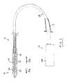
- the delivery cathetermay further comprise a ball joint located proximal of the stent accommodation region.
- the ball jointmay be formed in an outer tube at or leading to the distal portion.
- the proximal portioncan include a distal (first) sheath that is slidably configured to cover at least a portion of the distal end of the accommodation region and configured to slide distally to reveal the distal end of the accommodation region for the collapsible stent, and a proximal (second) sheath that is slidably configured to cover at least a portion of the proximal end of the accommodation region for the collapsible stent and to slide proximally to reveal the proximal end of the accommodation region for the collapsible stent.
- the distal sheath and the proximal sheathmeet at the proximal end of the distal sheath and the distal end of the proximal sheath when they cover the distal and proximal ends of the collapsible stent.
- the ball jointcan be less than 5 cm proximal of the stent accommodation region of the catheter. It can also be less than 2 cm proximal of the stent accommodation region of the catheter. It can also be less than 1 cm of the stent accommodation region of the catheter. It can also be between 1 and 2 cm proximal of the stent accommodation region of the catheter.
- the ball joint of the cardiac stent delivery systemcan also be hollow. Also, one or more inner tubular members can pass through the hollow portion of the ball joint. The ball joint can also allow the outer and inner tubular members to bend, according to some embodiments, at least 20° or at least 30° or at least 40° or at least 45°.
- the ball joint of the cardiac stent delivery cathetercan also allow an axial force to be applied on the inner tubular member and the outer tubular member causing the distal sheath to be moved distally and/or the proximal sheath to be moved proximally.
- This motion of the distal sheath distally and the proximal sheath proximallycan reveal the collapsible stent on the attachment region, for example.
- the ball joint of the cardiac stent delivery cathetercan also allow the outer and inner tubular members to rotate with regards to each other.
- the outer and inner tubular memberscan be allowed to rotate with regards to each other for one rotation, or for unlimited rotations, for example.
- the systemmay comprise:
- an aortic stent-valvecomprising a stent component and a plurality of valve leaflets supported by the stent component, the stent component having an inflow end and an outflow end and being self-expandable from a compressed state for delivery towards a functional state upon implantation, the stent component comprising outflow structure at or towards the outflow end, a crown intermediate the inflow and outflow ends, the crown having a free extremity intermediate the inflow and outflow ends and directed towards the outflow end, and the stent-component further comprising a fixation section between the crown and the inflow end;
- a delivery catheterhaving a distal portion for insertion into the anatomy, and a proximal portion, a stent-valve accommodation region at the distal portion for accommodating the stent-valve in the compressed state for delivery, the distal portion comprising a first sheath for covering at least a portion of the fixation section to constrain the fixation section compressed, and a second sheath for covering at least a portion of the arches and at least a portion of the crown to constrain the arches and the crown compressed.
- the second sheathmay be translatable in a proximal direction to uncover the crown and the outflow structure.
- the first sheathmay be translatable in a distal direction to uncover the fixation section.
- Use of such sheaths moving in opposite directionscan permit at least partial deployment of the crown and outflow structure without substantial distal extension of the catheter. It can also reduce the total distal extension of the catheter when the sheaths are open (compared to a catheter employing a single distally-moving sheath).
- the outflow sectionmay comprise a plurality of arches at the outflow end each having an apex at the outflow end.
- Translation of the second sheathmay uncover the crown for deployment followed by uncovering the outflow structure (e.g. arches) for deployment.
- the outflow structuree.g. arches
- Such a sequenceis different from that described in the aforementioned WO-A-2009/053497 and WO-A-2011/051043.
- deploying the outflow structure (e.g. arches) after the crownis still highly effective in permitting the arches to function.
- the outflow structuree.g. arches
- the outflow structuree.g. arches
- the outflow structuremay be deployed prior to uncovering of the fixation section for deployment.
- the outflow structure(e.g. arches) may be configured for aligning the stent-valve with respect to an axis of the ascending aorta by contact with a wall of the ascending aorta.
- the archesmay be bendable independently of each other.
- the crownmay be configured for engaging and/or seating against existing leaflets from an outflow side.
- the fixation sectionmay be configured for engaging an existing annulus.
- Deploying the outflow structure (e.g. arches) before the fixation sectionmay permit self-alignment of the stent-valve by the action of the outflow structure (e.g. arches), before the fixation section deploys to anchor the stent-valve at the annulus of the existing valve.
- the outflow structuree.g. arches
- the stent-valvemay be for use in a system as described above and/or for use with a delivery catheter as described above.
- the following definitionsare therefore intended to be combined with any of the foreogoing aspects.
- the stent-valvemay comprise a valve component and a plurality of leaflets supported by the valve component.
- the stent-valvemay further comprise any one or a combination of two of more of the following features, which are all optional:
- the stent componentmay be configured to be radially compressible into a compressed state and expandable to a functional state.
- the stent componentmay be self-expanding from the compressed state, or the stent component may be non-self-expanding (in which case the delivery catheter may comprise a device for applying an expansion force (for example, from within the stent-valve) to cause expansion).
- Non-limiting example materials for a self-expanding stent componentinclude shape memory materials, especially metals alloys, such as nitinol.
- Non-limiting example materials for a non-self-expanding stent-componentinclude shape memory materials, and stainless steel.
- the stent componentmay comprise commissural supports (e.g. posts) for supporting the valve leaflets.
- the commissural supportsmay support edges of valve leaflets that meet at the commissural supports.
- the commissural supportsmay be defined by a section of the stent component that is intermediate opposite end sections of the stent. Each commissural support may have opposite ends that each communicate with a respective stent section that is axially adjacent to the commissural support. The commissural support may optionally not have a free end.
- the commissural supportsmay each have a slot for receiving a tab of a leaflet.
- the commissural supportsmay further comprise a plurality of bores flanking one or both long sides of the slot. The bores may be configured for receiving suture thread.
- each commissural supportmay comprise a post.
- Each commissural supportmay have a wishbone shape.
- the wishbone shapemay include first and second legs diverging from one end of the post.
- the stent componentmay comprise a lattice structure having at least one row of cells, the lattice structure including a sequence of cells that repeats in the circumferential direction, the sequence including cell apexes defining: a first apex node communicating at least with a first leg of a wishbone commissural support, at least one free apex spanned by the wishbone commissural post, a second node apex communicating at least with a second leg of the wishbone commissural support, and at least one further node apex communicating with an element of a crown.
- the first and second node apexesmay communicate additionally with one or more respective elements of a crown.
- the commissural supportmay comprise a post communicating at one end with the legs of the wishbone shape, and communicating at the other end with an outflow section of the stent component (e.g. comprising stabilization arches).
- the above forms of constructioncan provide a stent that is functional to support a valve component, yet can be compressed to a small size.
- the stent-valve(e.g. stent component) may comprise at least one (and preferably a plurality) of attachment elements for cooperating with a stent-holder of the delivery catheter.
- Each attachment element(or at least one of the attachment elements) may comprise a U-shape portion joining two stent struts.
- U-shapeis used herein to include any shape including a generally arcuate apex, whether or not the sides are straight or curved, bulged outwardly, parallel or non-parallel. In a collapsed (e.g.
- the strutsmay lie adjacent each other at the attachment element, such that the arc of the U-shape portion extends around a first angle more than 180 degrees to define, for example, a closed or near closed (e.g. horseshoe shape) eyelet having an aperture larger than the spacing of the struts.
- a closed or near closede.g. horseshoe shape
- the horseshoe shape of the eyelet aperture and the adjacent space between the strutsmay together define a keyhole type shape.
- the strutsIn an expanded (or non-collapsed) condition of the stent when released from the accommodation region of the delivery catheter, the struts may move apart, and the arc of the U-shape portion may extend around a second angle that is less than the first angle, to at least partly open the eyelet further.
- the second anglemay be about 180 degrees or less.
- the attached elementIn the expanded condition, the attached element may define a substantially straight-sided U-shape with an arcuate apex.
- the delivery cathetermay comprise a sent-holder provided within the accommodation region.
- the stent-holdermay comprise
- the projectionmay be dimensioned such that, when the stent is in its collapsed condition, the projection is trapped within the eyelet and unable to pass between the adjacent struts, and/or
- the above formscan provide for a compact, yet reliable and self-opening and/or self-releasing attachment between a stent-valve and a delivery system.
- the stent-valvemay comprise at least two leaflets.
- the leafletsmay be of pericardium tissue, most preferably porcine pericardium tissue or bovine pericardium. Porcine pericardium may provide desirable tissue thinness. Bovine pericardium may be slightly thicker but more durable.
- Each valve leafletmay include at least two tabs.
- the tabsmay serve for supporting the leaflets relative to the stent component.
- the tabsmay be attached directly to commissural supports (e.g. posts) of the stent component.
- the tabsmay attach to attachment means provided on the commissural support.
- a tabmay pass through a slot in a commissural support, from an interior of the stent component to an exterior.
- the portion of the tab exterior to the stent componentmay be folded to lie against the commissural support and/or sutured to the commissural support.
- respective tabs of two adjacent leaflets that meet at the commissural supportpass through the same slot.
- Each tabmay be folded to lie against the exterior of the commissural support without overlapping the other tab.
- the two tabsoptionally are not directly attached to each other.
- the leafletsmay be attached to an inner skirt.
- the leafletsmay be attached to an interior portion of the inner skirt, the tabs passing through slots (e.g., slits) in the inner skirt to the exterior of the inner skirt.
- the inner skirtmay have scalloped clearances, each such clearance being spanned by a respective leaflet.
- the inner skirtmay have commissural portions or upstands in which the slots (e.g., slits) are provided.
- the material defining the inner skirtmay include integral extension portions that wrap at least around the commissural supports, for covering the commissural supports and/or for covering the leaflet tabs secured to the commissural supports.
- the extension portionsmay be sutured to the commissural supports.
- a combination of any two or all three of the above arrangementsmay be used.
- a pair of tabs of adjacent leafletsmay pass through a slot in the inner skirt, and through a slot in the commissural support.
- the tabsmay be folded back in opposite directions, and sutured to the exterior of the commissural support (optionally without the tabs being sutured directly to each other).
- One or more extensions of the inner skirt at the commissural supportmay be wrapped around the exterior of the commissural support to cover the tabs and/or the commissural support.
- the extension(s)may be sutured to the commissural support.
- the suturesmay pass through the same suture holes in the commissural support as those used for attaching the tabs.
- the extension(s)may extend axially beyond the tab(s), such that the edges of the tabs are shrouded and protected.
- the stent-valvemay comprise a stent-component, a plurality of valve leaflets mounted within the stent component, an inner skirt attached to the valve leaflets, the inner skirt extending at least partly within the stent component, and an outer skirt extending at least partly outside the stent component. At least a portion of the stent component over which at least one of the skirts extends, may comprise a lattice structure having at least one row of a plurality of cells.
- the inner and outer skirtsmay partly overlap, at least with respect to the surface of at least one of the skirts. Additionally or alternatively, the inner and outer skirts may not have any coterminous extremity. Additionally or alternatively, the outer skirt may extend further towards an inflow extremity of the stent component than does the inner skirt. Additionally or alternatively, the inner skirt may extend further towards an outflow extremity of the stent component than does the outer skirt.
- a function of the inner skirtmay be to define a conduit within the stent to channel blood towards the valve leaflets, and obstruct leakage of blood through interstices of the stent component (e.g., lattice interstices).
- a function of the outer skirtmay be to provide a seal surface outside the stent component for sealing with surrounding tissue, to obstruct leakage at the interface with surrounding tissue.
- both skirtsmay be beneficial in terms of obstructing leakage.
- the presence of both skirtscan add significantly to the thickness of material carried by the stent, and thereby increase the difficulty of compressing the stent-valve to a desirably small size.
- the benefits of both skirtscan be obtained, but with a reduced thickness profile in the regions where only one skirt extends. Overlapping the skirts can provide better sealing between the skirts than were the skirts to be arranged edge to edge on the interior and exterior respectively of the stent component (for example, especially bearing in mind that the stent-valve is to be deformed substantially by compression for delivery and re-expansion at implantation).
- the degree of skirt overlap in the axial directionmay, for example, by at least 1 mm, or at least 2 mm, or at least 3 mm, or at least 4 mm, or at least 5 mm, or at least 6 mm, or at least 7 mm, or at least 8 mm. Additionally or alternatively, the degree of skirt overlap in the axial direction may, for example, be less than 10 mm, or less than 9 mm, or less than 8 mm, or less than 7 mm, or less than 6 mm, or less than 5 mm, or less than 4 mm. For example, the degree of skirt overlap in the axial direction may be about 4-6 mm.
- At least one of the skirtsmay extend a non-overlapped axial distance of at least 1 mm away from the region of overlap.
- the non-overlapped distance for the or each skirtmay, for example, be at least 2 mm, or at least 3 mm, or at least 4 mm or at least 5 mm or at least 6 mm, or at least 7 mm or at least 8 mm or at least 9 mm, or at least 10 mm.
- the inflow end or edge of the stent componentmay have a zig-zag shape defined by a lattice structure of at least one row of cells.
- the zig-zag shapemay define an alternating sequence of free apexes (e.g., at an inflow extremity), and connected apexes (e.g. connected to lattice structure extending away from the inflow end towards the outflow end).
- the inner skirtmay extend only to the connected apexes.
- the outer skirtmay overlap the inner skirt and extend further than the inner skirt, to a level corresponding to at least some of the free apexes.
- the inner skirtmay be attached to an inflow edge and/or an outflow edge of valve leaflets.
- the inner skirtmay extend towards the inflow extremity of the stent component.
- the outer skirtmay overlap only partly the inner skirt while remaining spaced from an uppermost edge of the inner skirt.
- the outer skirtmay extend towards (or optionally to) the inflow extremity of the stent component.
- the outer skirtmay optionally not overlap (e.g., directly or indirectly through the stent component) any portion of the leaflets.
- the inner skirt and/or outer skirtmay be of any suitable material, such as pericardial tissue (e.g. porcine pericardium for thinness), PET, Dacron, etc.
- pericardial tissuee.g. porcine pericardium for thinness
- PETe.g. PET
- Dacrone.g. PET
- the inner and outer skirtsmay optionally be made of the same material as each other.
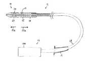
- FIG. 1is a schematic partial section view of a delivery catheter and stent-valve
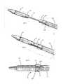
- FIG. 2is a schematic section showing the distal portion of the delivery catheter partly open
- FIG. 3is a schematic section showing the distal portion of the delivery catheter full open
- FIG. 4is a schematic section showing the distal portion of the delivery catheter in more detail.
- the axial (horizontal) scaleis compressed relative to the radial (vertical) scale to permit all elements to be shown in a single view;
- FIG. 5is a schematic perspective view showing the distal portion of the delivery catheter full open deploying the interface element
- FIG. 6is a schematic side view of the interface element in isolation, shown in a deployed condition
- FIG. 7is a schematic perspective view showing the initial closing of the second sheath
- FIG. 8is a schematic perspective view showing the second sheath in its closed position
- FIG. 9is a schematic side view showing the first and second sheaths reclosed with the interface element deployed
- FIGS. 10 a - care schematic sections showing in isolation example attachment elements of a stent-valve for attachment to a stent-holder of the delivery catheter. The attachment elements are shown in an expanded condition of the stent-valve;
- FIG. 11is a schematic perspective view showing in isolation one example of a stent holder for the delivery catheter
- FIG. 12is a schematic side view illustrating engagement between the attachment element of FIG. 10 a and the stent holder of FIG. 11 ;
- FIG. 13is a schematic side view illustrating engagement between the attachment elements of FIGS. 10 a / 10 b and a second example of stent holder;
- FIG. 14is a schematic perspective section illustrating petals on the stent holder
- FIG. 15is a schematic section similar to FIG. 14 illustrating a combined stent holder and interface element
- FIG. 16is a schematic section illustrating a handle with controls at the proximal end of the deliver catheter.
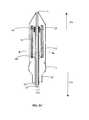
- FIG. 17is a schematic side view illustrating one example of stent-valve
- FIG. 18is a schematic profile view illustrating the profile envelope of the stent component of the stent-valve of FIG. 17 ;
- FIG. 19is a schematic view illustrating a developed geometry of the stent component in a single plane
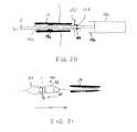
- FIG. 20is a schematic section illustrating a liner sleeve for the catheter
- FIG. 21is a schematic section illustrating the interface member for streamlining the stent holder to permit withdrawal of the catheter through an introducer while open.
- the sheathsare omitted to avoid clutter;
- FIG. 22is a schematic perspective view of a stent holder in isolation, as a single-piece item having a geometry similar to FIG. 13 ;
- FIG. 23is a schematic perspective view of the stent holder of FIG. 22 with a sheath thereon, and mounted on the stent holder support tube;
- FIG. 24is a schematic section illustrating a delivery catheter with a ball joint.
- the delivery catheter 12may have a distal portion 14 towards one end for insertion into a patient's anatomy, and a proximal portion 16 towards an opposite end from which the delivery catheter is manipulated in use by an operator.
- a barrel or stem portion 15may extend between the distal and proximal portions.
- distal and proximalfor the delivery catheter may refer to relative position with respect to an operator.
- the distal portion 14 of the catheter 12may comprise an accommodation region 18 for accommodating the stent-valve 10 in a collapsed form for introduction into the anatomy.
- the stent-valve 10may be a cardiac stent-valve.
- the delivery catheter 12may be configured to permit delivery of the stent-valve 10 to, and deployment at, a desired site of implantation while the heart remains beating, for example, using a minimally invasive surgical and/or percutaneous procedure.
- the catheter 12may be configured for introduction into the anatomical vascular system, and for advancement along the vasculature system to the desired site of implantation.
- the catheter 12may be configured for introduction into the femoral artery, and guided retrograde via the descending aorta, aortic arch, and ascending aorta to the heart (sometimes called a transfemoral access).
- the catheter 12may have a length of at least about 1 m to provide sufficient length insertable into the anatomy.
- the catheter 12may be insertable via the subclavian artery and guided retrograde to the heart (sometimes call transubclavian access).
- the catheter 12may be inserted directly into a chamber of the heart such as a ventricle (for example, left ventricle) via a direct access route while the heart remains beating.
- a direct access routemay be through an aperture opened in the apex of the heart (sometimes called a transapical access).
- the size of access aperture into the anatomymay depend on the outer diameter of the distal portion 14 .
- the barrel portion 15may be slightly smaller than, or the same diameter as, the distal portion 14 as desired.
- An introducer 19for example, a standard arterial introducer, may optionally be used at the access aperture into the anatomy.
- the optional introducer 19may have a size of 20 French or smaller, for example, 18 French or smaller.
- the distal portion 14may be dimensioned for insertion through such a size of introducer 19 .
- the stent-valve 10may be expandable from a compressed or collapsed condition to a functional and/or expanded condition, in order to anchor the stent-valve 10 at the implantation site.
- the stent-valve 10may form a friction and/or interference fit with respect to the native anatomy.
- Various shapes and geometries of stent-valve 10may be used to fit the anatomy at the site of implantation.
- a generally cylindrical stent-valve 10is illustrated here for clarity, but the invention is not limited to a cylindrical shape, and may be especially advantageous with non-cylindrical shaped stent-valves 10 .
- a more detailed example of stent-valve 10is described later, and all details of the delivery catheter 12 are explicitly applicable to the stent-valve shape described later.
- the stent-valve 10may be self-expanding and/or may be configured to be expandable by swelling of an expander (for example, a balloon not shown).
- Self-expanding stent-valves 10may be constructed from, or use, shape-memory material, for example a shape-memory metal alloy (such as nitinol).
- a self-expanding stent-valve 10may be retained in its compressed state by being constrained within a sheath 20 / 22 of the delivery catheter 12 . Upon at least partial release from the sheath 20 / 22 , the released portion of the stent-valve 10 may be free to expand.
- Non-self-expanding stent-valves 10may also be made of shape-memory material, or from stainless steel, or cobalt-chromium alloy.
- a non-self-expanding stent-valve 10may also be contained at least partly within a sheath 20 / 22 to protect the stent-valve 10 and/or facilitate smooth introduction through the anatomy.
- the distal portion 14 of the catheter 12may comprise at least one sheath 20 and/or 22 that is translatable between a closed position at least partly covering the accommodation region 18 and/or the stent-valve 10 therein, and an open position at least partly opening or exposing the accommodation region 18 and/or at stent-valve 10 therein.
- the catheter 12comprises two sheaths 20 and 22 , both shown in their respective closed positions in FIG. 1 to at least partly (optionally substantially entirely) cover the stent-valve 10 in the accommodation region 18 .
- the sheaths 20 and 22may be translatable in opposite directions to respective open positions.
- a firste.g.
- first and second opposed sheaths 20 and 22may provide good versatility for release of the stent-valve 12 from the accommodation region.
- a portion 10 a of the stent-valve 10 previously covered by the second sheath 22may be released (at least partly) before a portion 10 b of the stent-valve 10 covered by the first sheath 20 .
- the portion 10 bmay be released subsequently by translation of the first sheath 20 to or towards its open position ( FIG. 3 ).
- the length of the second sheath 22may be greater than the length of the first sheath 20 .
- the ratio of the second sheath length divided by the first sheath lengthmay be at least 1.1, optionally at least 1.2, optionally at least 1.3, optionally at least 1.4, optionally at least 1.5, optionally at least 1.6, optionally at least 1.7, optionally at least 1.8, optionally at least 1.9, optionally at least 2.0, optionally at least 2.1, optionally at least 2.2, optionally at least 2.3, optionally at least 2.4, optionally at least 2.5, optionally at least 2.6, optionally at least 2.7, optionally at least 2.8, optionally at least 2.9, optionally at least 3, optionally at least 3.5, optionally at least 4 or optionally at least 4.5, or optionally at least 5.
- first sheath 20may reduce risk of trauma in use.
- the first sheath 20advances distally along a path that may be less controlled than the second sheath that benefits from a more controlled path defined by the path adopted by the barrel portion 15 of the catheter.
- the first sheath 20may advance into the ventricle of the heart.
- Use of a relatively short first sheath 20may reduce the degree to which the catheter 12 has to penetrate into the ventricle, and risk interfering with delicate tissue surfaces.
- direct accesse.g. transapical access
- the first sheath 20may advance into the ascending aorta.
- Use of a relatively short first sheath 20may reduce the degree to which the first sheath 20 has to penetrate the space of the ascending aorta, and risk interfering with the aorta wall.
- One or both of the sheaths 20 and 22may be of plastics optionally including reinforcement to resist radial expansion of the sheath.
- plasticsis a poly ether block amide (PEBA), for example PEBAX (TM).
- PEBApoly ether block amide
- Reinforcementmay be provided by a helical coil embedded within the sheath.
- the helical coilmay be of metal, for example, stainless steel filament.
- the sheaths 20 and 22may have the same inner and/or outer diameter.
- the sheaths 20 and 22may be configured not to overlap each other. Avoiding an overlap can avoid excess diameter of the distal portion that might otherwise be caused by the sheath walls overlapping each other.
- the sheaths 20 and 22may be capable of being positioned such that the sheaths 20 and 22 meet substantially end to end. Alternatively, the sheaths 20 and 22 may be configured such that the sheaths 20 and 22 always remain spaced from each other, even in mutually closed positions of the first and second sheaths 20 and 22 .
- the minimum spacingmay be at least 1 mm, or at least 2 mm, or at least 3 mm, or at least 4 mm, or at least 5 mm, or at least 6 mm. Additionally or alternatively, the spacing may be less than 10 mm, or less than 9 mm, or less than 8 mm, or less than 7 mm, or less than 6 mm, or less than 5 mm. In one form, the spacing is between about 4 mm and about 6 mm.
- a stent-holder 24may retain the stent-valve 10 axially in position and/or restrain the stent-valve 10 against axial movement.
- the stent-holder 24is represented purely schematically in FIGS. 1-3 , and is described in more detail later.
- the stent-holder 24may prevent and/or obstruct any tendency of the stent-valve 10 to be dragged by translation of a sheath 20 or 22 .
- the stent-holder 24may prevent and/or obstruct any tendency for a self-expanding stent-valve 10 to jump free of the catheter if only a small portion of the stent-valve 10 remains constrained by the sheath 20 or 22 .
- the stent holder 24may be positioned in the accommodation region 18 at a position appropriate to engage the stent-valve 10 until final release of the stent-valve 10 from the accommodation region.
- a distal portion of the stent-valve 10may be intended to be released last, and the stent-holder 24 may be positioned towards the distal end of the accommodation region 18 .
- the proximal portion of the stent-valve 10is intended to be released last, the stent-holder 24 could instead be positioned towards the proximal end of the accommodation region 18 .
- FIG. 4illustrates one example construction of the distal portion 14 of the catheter 12 in more detail.
- the barrel portion 15comprises a plurality of flexible tubes 26 , 28 and 30 extending between the distal portion 14 and the proximal portion 16 .
- the tubes 26 - 30may be nested at least one within another, and coupled to the sheaths 20 and 22 and the stent holder 24 .
- the sheaths 20 and 22may be translated by relative translation of respective tubes.
- At least one, optionally two, optionally three, optionally more, of the flexible tubesmay be of plastics, optionally with reinforcement.
- At least one tubemay comprise a combination of polyamide material and polyimide material.
- the polyamide and polyimidemay be layered one over the other to define an integral tubular laminate having a radially inner layer and a radially outer layer, for example, by coextrusion.
- the radially inner layermay be of polyimide, and the radially outer layer of polyamide.
- Polyimidehas a desirably high modulus and strength, but is expensive to manufacture in significant thickness.
- the addition of a polyamide layercan complement the physical properties of the polyimide, providing a thicker tube of high tensile and column strength, good flexibility, and high modulus.
- the polyimide and polyamide combinationcan provide properties similar to far more expensive materials such as PEEK (poly-ether-ether-ketone) tubing that is sometimes used in catheter delivery systems.
- reinforcementmay be provided by a braid, for example, a metal braid, within the plastics.
- the plasticsmay, for example, be a polyamide, and/or the braid of stainless steel filament.
- the reinforcementmay, compared to a tube of the same plastics without the reinforcement: (i) increase the modulus of elasticity yet retain flexibility; and/or (ii) improve resistance to kinking when the tube is flexed; and/or (iii) increase the ability for transmission of torque from the proximal portion to the distal portion.
- Respective different tubesmay have respective different braids.
- the braidsmay be defined by a density or PPI (“peaks per inch”) and/or by a braid angle.
- a lower densitymay imply that the winding angle is closer to the axial direction; a higher density implies that the winding angle is closer to the radial direction.
- One braid(for example, a more radially outer tube) may have a lower density (e.g. PPI) than another braid (for example, for a more radially inner tube).
- the densitymay, for example, be at least twice, optionally at least 5 times, optionally at least 10 times, the density of the other.
- a higher densitymay provide for greater column strength.
- a lower density and/or a braid angle closer to 45 degreesmay provide for greater torque transmission.
- the combination of two different braid densitiesmay provide better characteristics than an identical braid in both tubes.
- one tubemay have a braid PPI of between about 5 and about 10, for example, about 8. Additionally or alternatively, the other tube may have a braid PPI of between about 50 and about 100, for example, about 80.
- a first tube 26may be coupled for controlling the stent holder 24 .
- the first tube 26may optionally comprise plastics with braid reinforcement, as described above.
- a first tube coupling 34may couple the first tube 26 to a stent holder support tube 32 on which the stent holder 24 is mounted.
- the stent holder support tube 32may be inserted into the end of the first tube 26 and/or attached thereto, at the first tube coupling 34 .
- the stent holder support tube 32may have a smaller outer diameter than the first tube 26 .
- the stent holder support tube 32may be less flexible than the first tube 26 .
- the stent holder support tube 32may, for example, be of polyimide.
- the stent holder support tube 32may act as an extension of the first tube 26 adapted to pass within the relatively confined space of the accommodation region 18 .
- the reduced flexibilitycan compensate for smaller diameter to provide adequate column strength along the axis of the stent holder support tube 32 .
- a second tube 28may be coupled to control the first (distal) sheath 20 .
- the second tube 28may optionally comprise a tubular laminate of a polyimide layer radially within a polyamide layer, including any of the associated details described above.
- the second tube 28may be nested within the first tube 26 and be translatable relative thereto.
- the second tube 28may include a distal extension 38 having a smaller outer diameter than a main portion of the second tube, and communicating therewith at an inter-face point 36 .
- the distal extension 38may, for example, be an extension of the polyimide inner layer without the polyamide outer.
- the distal extension 38may support (directly or indirectly) the first sheath 20 .
- the sheath 20is mounted to the distal extension 38 by a tip member 40 .
- the tip member 40may have a tapered atraumatic shape to aid advancement of the catheter 12 within the anatomy without trauma to the surrounding anatomy.
- the tip member 40may have a rear extension 42 around which the first sheath 20 is attached immovably to the tip member 40 .
- the smaller outer diameter of the distal extension 38may be configured to pass within the small diameter of the stent holder support tube 32 .
- the distal extension 38may translate within the stent holder support tube 32 , and move therewithin as the second tube 28 moves within the first tube 26 . To move the first sheath 20 to its open position, a translation force may be applied to advance the second tube 28 distally relative to the first tube 26 .
- the translation force and movementis applied from the second tube 28 to the distal extension 38 , which pulls the first sheath 20 distally (for example, the translation force and movement being applied through the tip member 40 ).
- the stent holder 24may hold the stent-valve 10 relatively stationary under the control of the first tube 26 and the stent holder support tube 32 on which the stent holder 24 is mounted.
- the optional diameter difference between the first tube 26 and the stent holder support tube 32may define a profile step or change at the first tube coupling 34 .
- the optional diameter difference between the second tube 28 and the distal extension 38may define a profile step or change at the interface point 36 .
- the outer diameter of the second tube 28may be greater than the inner diameter of the stent holder support tube 34 (for example such that the second tube cannot translate beyond the first tube coupling 34 ).
- the first tube coupling 34 and the interface point 36may be spaced apart.
- the interface point 36may be proximal of the first tube coupling 34 .
- the spacingmay be at least as large as the amount of linear translation of the first sheath 20 when the sheath moves between its open and closed positions. The spacing may permit the interface point 36 to advance distally.
- the second tube 28 and the distal extension 38may define a lumen 46 extending through the catheter.
- the lumen 46may be a guidewire receiving lumen for receiving a guide wire (not shown) along which the catheter 12 may be advanced within the anatomy to guide the distal portion 14 to the desired site of implantation.
- a third tube 30may be coupled for controlling the second (proximal) sheath 22 .
- the third tube 30may optionally comprise plastics with braid reinforcement, as described above.
- the first tube 26may be nested with the third tube 30 .
- the third tubemay be translatable relative to the first tube 26 and/or the second tube 28 .
- a third tube coupling 44may couple the third tube 30 to the second sheath 22 .
- the third tube coupling 44may include a tapered surface for defining a smooth atraumatic transition between the outer surfaces of the third tube 30 and the second sheath 22 .
- the third tube coupling 44may be integral with the second sheath 22 , and may be a narrowed end portion thereof.
- a translation force(e.g. tension) may be applied to retract the third tube 30 proximally relative to the first tube 26 .
- the translation force and movementis applied from the third tube 30 to the second sheath 22 , which pulls the second sheath 22 proximally.
- the stent holder 24may hold the stent-valve 10 relatively stationary under the control of the first tube 26 and the stent holder support tube 32 on which the stent holder 24 is mounted.
- the braids in the first and third tubes 26 and 30may have different characteristics according to their respective inner and outer radial relationship.
- first and second sheathsare translated to their open position may depend on the design of the stent-valve.
- the second sheath 22may be translated before the first sheath 20 .
- An example deployment sequenceis described later.
- At least one of the tubesmay be pre-tensionable at least prior to opening the distal potion 14 for deploying a stent-valve. Pre-tensioning the tube may compensate for any tendency of the portion of the catheter controlled by the tube to creep distally in response to forces applied during manipulation to open other portion(s) of the catheter controlled by other tube(s).
- the second tube 28may be pre-tensioned from the proximal end, in order to prevent the first sheath 20 from creeping distally when the second sheath 22 is pulled back while applying a maintaining force to the first tube 26 . Creeping of the first sheath 20 is undesirable as it may result in movement of the deployment position, or premature release of the stent.
- Pre-tensioning the second tube 28may maintain the first sheath 20 firmly closed, thereby preventing premature release.
- the pre-tensionis removed as part of the transition to applying a pushing force.
- the pre-tensionmay be generated by controls within the handle, as described later.
- the amount of pre-tensionmay be sufficient to counter the reaction force applied through the first tube when translating the third tube to move the second sheath proximally.
- the amount of pre-tension appropriate for a specific embodiment of delivery cathetermay, for example, be derivable empirically.
- the above arrangementscan provide a delivery catheter that combines the desirable properties of compact size, good flexibility without kinking, good transmission of torque, good column strength, and avoidance of distal creep of a sheath, all without using exotic materials that are prohibitively expensive.
- the inventionalso contemplates inclusion of a ball joint (not shown) that is just proximal of the distal portion.
- the ball jointmay be provided in the third tube, or the connecting portion between the third tube and the second sheath.
- the ball jointmay be hollow to allow the first and second tubes to pass therethrough.
- first and second sheaths 20 and 22may have respective mouths or open ends 20 b, 22 b, respectively, that may generally confront or lap one another when the (or each) sheath 20 , 22 is in the closed position, or may remain slightly spaced apart.
- both sheaths 20 and 22are translatable, but in some embodiments it is possible that only one of the sheaths 20 and 22 might be translatable.
- the presence of the stent-valve 10 within the accommodation region 18may cause the sheaths 20 and 22 to be generally aligned in register. Even if the open ends 20 b and 22 b are spaced from each other or confront each other without lapping, the open ends 20 b and 22 b may thus align in register. Such alignment may avoid any abrupt edges in the outer profile of the sheaths, and facilitate insertion of the distal portion 14 into the anatomy (optionally through the introducer 19 and/or advancement through vasculature).
- the open ends 20 b and 22 bno longer to be closely aligned.
- Such misalignmentmay result in an abrupt edge in a case of confronting or slightly spaced open ends and/or difficulty of re-engaging the open ends in the case of trying to lap the open ends. It may be desirable to avoid an abrupt edge, especially at the open end 20 b of the first sheath 20 .
- the open end 20 bmay interfere with native tissue on the return path, or it may make it difficult to extract the distal portion through an introducer 19 , especially if the distal portion 14 is a tight fit within the introducer 19 .
- the second sheath 22may be guided smoothly into the introducer 19 by the ramp surface 44 at the third tube coupling 44 .
- an abrupt edge at the open end 20 b of the first sheath 20may obstruct smooth passage of the first sheath 20 for withdrawal through the introducer 19 .
- an exposed abrupt edgee.g. end face 92 in FIGS. 11-13
- the second sheath 22may be guided smoothly into the introducer 19 by the ramp surface 44 at the third tube coupling 44 .
- the abrupt edge 92 of the stent holder 24may obstruct smooth passage of the first sheath 20 for withdrawal through the introducer 19 .
- the distal portion 14may comprise an interface member 50 ( FIGS. 4 to 9 ).
- the interface member 50may be deployable to:
- the interface member 50may be deployable as part of the sequence during or after release of the stent-valve 10 .
- the interface member 50may be translatable along the catheter axis from a non-deployed condition ( FIG. 4 ) to a deployed condition ( FIGS. 5 to 9 ).
- the interface member 50may be initially be stowed within one of the sheaths (for example the second sheath 22 ) in a non-deployed condition, and be translatable to or towards the open end of the sheath ( 22 ) to transition to its deployed condition. Stowing a movable interface member 50 initially within the second sheath 22 may avoid having to elongate the first sheath 20 unnecessarily to accommodate the interface member 50 .
- the interface member 50may be substantially freely translatable within a predetermined range of movement, and be configured to move with, or in response to, sheath movement.
- the interface member 50may be referred to as a shuttle.
- the interface member 50may be slidable (e.g. captively slidable) on one of the tubes 26 , 28 , 32 , 38 .
- the interface member 50(or at least a portion 52 thereof) may be expandable. Transition from a non-deployed condition ( FIG. 4 ) to a deployed condition ( FIGS. 5 to 9 ) may include expansion of the expandable portion 52 .
- the expandable portion 52 of the interface membermay be radially expandable.
- the expandable portionmay be self-expandable from a compressed state.
- the interface member 50may be both movable and self-expandable. Referring to FIG. 4 , the interface member 50 may initially be stowed within one of the sheaths (for example the second sheath 22 as mentioned above) in a compressed non-deployed condition. The sheath 22 may constrain the interface member 50 in a compressed condition. The interface member 50 may be accommodated at one end of the accommodation region 18 where the interface member 50 may not interfere with the stent-valve 10 .
- the second sheath 22may be retracted proximally.
- travel of the interface member 50 in the proximal directionmay be restrained, for example, by the step profile of the first tube coupling 34 .
- Retraction of the second sheath 22may therefore cause relative movement between the second sheath 22 and the interface member 50 , resulting in the interface member 50 transitioning towards the open end 22 b of the sheath 22 .
- the interface member 50may no longer be constrained by the sheath 22 , the interface member 50 (or the portion 52 ) may self-expand.
- the interface member 50may become too large to be received again entirely within the sheath 22 .
- the interface member 50may at least partly “float” captive on the catheter between the stent holder 24 and the second sheath 22 .
- the interface member 50may at least partly self-locate or “float” at the open end 22 b.
- the interface member 50may be pushed distally towards the stent holder 24 and/or the open end 20 b of the first sheath.
- the interface member 50may be pushed distally until its travel is stopped by the stent holder 24 and/or the first sheath 20 .
- the interface member 50may advance until its travel is stopped by the stent holder 24 . Thereafter, when the first sheath 20 is closed, the interface member 50 may cooperate with the open end 20 b of the first sheath 20 as explained above.
- the interface member 50may be dimensioned at one end, or both ends, to be partly insertable into a respective open end of a sheath even when the expandable portion 52 (for example, intermediate the ends) is expanded and is oversize with respect to the open ends of the sheaths.
- Such insertioncan provide positive engagement and cooperation between the (or each) sheath and the inter-face member.
- Such insertioncan also provide a degree of self-alignment or self-centring between the (or each) sheath and the interface member. If both ends of the shuttle insert into respective sheaths, the sheaths may also self-align or self-centre in register with each other.
- the expandable portion 52 of the interface member 50may have a generally smooth annular bulge, or bulb, shape.
- the expandable portionmay have generally rounded or ramp surfaces at its opposite axial ends.
- Such a shape or shapesmay provide a smooth transition between the interface member 50 and each open end 20 b and 22 b, and/or a generally smooth profile or bridge between the open ends 20 b and 22 b.
- the shapemay further enhance self-alignment or self-centring of the open ends 20 b and 22 b in register with each other.
- the expandable portion 52may be dimensioned such that, in the expanded state of the expandable portion 52 , at least one of the open ends 20 b and 22 b will not pass entirely over the expandable portion. For example, in the case of confronting open ends 20 b and 22 b, optionally neither open end 20 b and 22 b may pass entirely over the expandable portion 52 . In the case of lapping open ends 20 b and 22 b, optionally one of the open ends may pass over the expandable portion 52 .
- the ends of the interface membermay be generally asymmetric.
- the proximal end 62may be formed as a cone.
- the cone shapemay provide a mounting surface for an optional skirt 60 described below, and/or provide a nesting profile to fit the within the third tube coupling 44 .
- the distal end 64may be formed as a generally annular rim with a smooth, e.g. rounded, edge for guiding the open end 20 b of the first sheath 20 as the first sheath 20 is closed thereover.
- the catheter 12may be desired to remove the catheter 12 from the body while the distal portion 14 remains in an “open” condition.
- at least the first sheath 20may remain “open”, whether or not the second sheath 22 is left “open” or is at least partly closed.
- the stent holder 24 and the interface member 50may remain exposed at the distal portion 14 .
- the interface member 50may tend to slide towards the stent holder 24 , either as a result of movement through the anatomy, or when the distal portion reaches the site of a closely fitting introducer 19 .
- the interface member 50may cooperate with the stent holder 24 to provide a more streamlined profile than the abrupt edge 92 .
- the interface member 50may comprise a conical surface 62 that defines a smooth ramp profile that will slide over the edge of an introducer 19 to guide the stent-holder 24 into the interior of the introducer and/or through the haemostasis valve.
- the interface member 50may comprise an enlarged oversize portion 52 that acts as a stop to prevent the interface member 50 from passing through the introducer until the interface member 50 abuts or engages the stent holder 24 . At that point, continued pulling to withdraw the catheter causes the enlarged portion 52 to collapse slightly, allowing the interface member 50 and stent holder 24 to pass smoothly through the introducer.
- the interface member 50may optionally be configured to form a snug interference fit over the end of the stent holder 24 so that it remains in intimate contact with the stent holder 24 .
- the interface member 50 as described abovemay comprise any suitable materials, including one or more of: plastics, resiliently compressible plastics, metal and shape-memory alloys (e.g. nitinol).
- the interface member 50comprises a generally non-compressible core member 54 carrying a shell 56 defining the expandable portion 52 .
- the non-compressible coremay, for example, be of plastics.
- the core member 54may be longer than the shell 56 , and define the end profiles 62 and 64 described above.
- the shell 56may, for example, be of metal or shape-memory alloy (e.g. nitinol) to provide a well-defined expanded shape.
- the expandable portion 52may comprise segments defining a cage-like bulge or bulb.
- the interface member 50may optionally comprise a flexible sleeve or skirt 60 .
- the sleeve or skirt 60may optionally be constructed as plural petals or segments of material that may overlap or not overlap, and collectively behave as a sleeve or skirt, and all references herein to a skirt are intended to refer also to such petals or segments.
- the skirt 60may be deployable from a folded or collapsed state to an expanded state.
- the skirt 60may be substantially self expanding. In the folded/collapsed state, the skirt 60 may be retained and/or restrained within one of the sheaths 20 and 22 .
- the skirt 60may be dimensioned to fit outside the open end 20 b, 22 b or at least one of the sheaths 20 , 22 , respectively.
- the skirt 60may cover at least partly the open end 20 b of the first sheath 20 .
- the skirt 60may be made of any suitable material, for example, flexible plastics.
- the skirt 60may be cut from a shaped balloon member, for example, as used in a known balloon catheter.
- a balloon cathetermay be used for valvuloplasty.
- Such a balloonmay be molded in its expanded shape, and a skirt 60 cut from such a balloon may be self-biased towards the expanded shape, but also be flexible and easily foldable to a collapsed state.
- Such a balloonis also designed to be of thin material having atraumatic characteristics.
- the skirt 60may be bonded to be an integral part of the interface member 50 .
- the skirt 60may be bonded to the proximal cone 62 .
- the cone 62may provide a suitable divergent surface for supporting the natural shape of the skirt 60 .
- the deployable interface member 50 and/or skirt 60could be substantially stationary with respect to the stent holder 24 .
- the deployable interface member 50 and/or skirt 60may be mounted on the stent holder 24 .
- FIGS. 10 a - cillustrate different examples of attachment element 68 of the stent-valve for engaging different examples of stent holder 24 , as illustrated in FIGS. 11-13 and 22 .
- the stent-valvemay comprise at least one attachment element 68 , optionally two or three attachment elements 68 , optionally more.
- each attachment element 68may be defined by an apex 74 or 76 , joining first and second struts 70 and 72 that extend from an end of the stent-valve 10 .
- the struts 70 and 72may be members defining a lattice or skeletal stent structure of the stent-valve 10 . In the case of a lattice, the cell associated with the struts 70 and 72 may project axially beyond neighbouring cells of the lattice.
- the struts 70 and 72may extend generally linearly to meet at apex 74 defining a generally V-shape.
- the apex 76is slightly different by incorporating a U-shape between the ends of the struts 70 and 72 .
- the U-shapemay be straight sided (e.g., FIG. 10 b ) or it may have curved sides (e.g. FIG. 10 c ).
- a two-piece example construction of stent holder 24may generally comprise first and second parts 78 and 80 assembled together.
- the first part 78may comprise a hub 82 from which project a plurality of projections 84 .
- the second part 80may comprise a casing having a hollow interior for fitting around at least a portion of the hub 82 from which the projections 84 project, and defining interstices 86 for accommodating the locking projections 84 with a space or clearance 88 therearound.
- the casingmay be forked to define the interstices.
- each interstice 86may optionally be rounded or chamfered.
- a two-part assemblymay enable a complex shape of stent holder 24 to be formed reliably and cost effectively. It may also permit different materials to be used as appropriate (for example, the first part may be of metal for strength, and the second part may be of plastics). However, as already mentioned, the stent-holder 24 may be formed as unitary item instead of an assembly of plural parts.
- the projections 84may be configured for fitting within the interior of the apex 74 or 76 of each attachment element 68 , when the stent-valve 10 is in its collapsed state.
- the engagement between the projection 84 and the apex 74 / 76traps the attachment element (and hence the stent-valve 10 ) against axial movement, at least in an axial direction away from the stent holder 24 .
- the projection 84may be referred to as a radial projection because it generally projects in a radial direction.
- the projection, or an edge thereofmay be inclined towards the distal direction, by an angle of, for example, not more than about 20 degrees, optionally not more than about 10 degrees, optionally not more than about 5 degrees.
- the projection 84has an elongate blade or fin shape, suitable for fitting within the interior of apex 74 ( FIG. 10 a ).
- Use of a fin or bladecan enable the projection 84 to have a desirably thin shape, while remaining strong (especially in the axial, elongate direction).
- the shape of the interstice 86 cupping the apex 74 , and/or engagement between an end face 92 of the stent holder 24 and neighbouring cell apexes of the stentmay restrain the stent-valve 10 against axial movement in the opposite direction.
- the stent-valve 10may thereby be retained firmly in position until expansion of the stent-valve 10 may disengage the or each attachment element 68 from the stent-holder 24 .
- the attachment elementsmay disengage when the portion of the stent-valve 10 from which the attachment elements 68 extend, is uncovered by a sheath (for example, the first sheath 20 ).
- a sheathfor example, the first sheath 20
- the struts 70 and 72move apart to open the V-shape of the apex 74 .
- the V-shapeopens, this enlarges the interior of the attachment element 68 to facilitate disengagement between the projection 84 and the apex 74 .
- the chamfered edge 90 of the interstice 86also acts as a ramp surface to “lift” radially the struts 70 and 72 out of the clearance 88 as the struts 70 and 72 expand circumferentially and bear against the edge 90 .
- the attachment elements 68may stick accidentally within the interstice 86 , the attachment elements 68 may be freed by slight rotation and/or axial displacement of the catheter, to promote further riding against the edge 90 .
- the projections 84are fingers or pins, suitable for fitting within the interior of apex 76 ( FIGS. 10 b / c ).
- Each pinFIG. 13
- the struts 70 and 72may lie closely adjacent each other at the attachment element 68 , such that the arc of the U-shape portion 76 extends around a first angle more than 180 degrees to define a closed or near closed eyelet having an aperture larger than the spacing of the struts, to accommodate the pin 84 .
- the U-shapemay be referred to as a horseshoe U-shape.
- the eyelet aperture and space between the strutsmay together define a keyhole type shape.
- the struts 70 and 72may bear against each other at the attachment element 68 to close the eyelet. Either arrangement can restrain the attachment element 68 in both axial directions, merely by engagement between the attachment element 68 and the projection 84 . This may be advantageous by enabling a larger chamfer surface to be used at the edge 90 of the interstice 86 and/or at the end face 92 of the stent-holder.
- a chamfered end face 92may be desirable to facilitate withdrawal of the stent holder 24 and first sheath 20 through the stent-valve 10 once implanted.
- the struts 70 and 72may move apart, and the arc of the U-shape apex 76 may extend around a second angle that is less than the first angle, to at least partly open the eyelet.
- the second anglemay be about 180 degrees or less.
- the apexmay have a substantially straight-sided U-shape.
- opening of the apex 86may facilitate disengagement from the projection 84 .
- the chamfered edge 90 of the interstice 86also acts as a ramp surface to “lift” radially the struts 70 and 72 out of the clearance 88 as the struts 70 and 72 expand circumferentially and bear against the edge 90 .
- FIG. 22shows a stent holder equivalent to FIG. 13 , optionally for production as a single-piece item.
- All of the stent holders illustrated in FIGS. 11-13 and 22illustrate the provision of at least one ramp surface extending partly around each projection, to define ramp surface portions circumferentially either side of the projection and axially (e.g. distally) to one side of the projection.
- the ramp surface portionsare inclined outwardly away from the projections.
- the clearance around the projectionis open to the other axial (proximal side) and/or open radially outwardly.
- the radial height of the projection 84may be accommodated entirely or at least substantially within the profile of the stent holder body.
- the stent holder bodymay be a surface of revolution.
- the ramp surfaceextends to the floor of the clearance or interstice around the projection 84 .
- the ramp surfacemay generally be inclined at an angle of between about 20 and about 40 degrees, optionally around 30 or 35 degrees.
- the stent-holder 24may carry a skirt (or may also be referred to as sleeve) 94 .
- the skirt 94may optionally be constructed as plural petals or segments of material that collectively behave as a sleeve or skirt, and all references herein to a sleeve/skirt are intended to refer also to such petals or segments.
- the skirt 94may be similar to the skirt 60 described above, and the same constructional details may be used.
- FIG. 23illustrates one example structure in more detail.
- the skirt 94may comprise a generally tubular sleeve section 94 a and a plurality of cuts or slits 94 b defining joined petals or segments 94 c.
- the petals 94 cmay substantially cover the projections 84 and/or the radial recess therearound.
- the slits 94 bmay permit the petals 94 c to fold or flex outwardly open.
- the slits 94 bmay be aligned generally with the projections 84 or the radial recesses therearound. Such positioning of the slits 94 b can ensure that the petals 94 c do not obstruct expansion and detachment of the attachment elements of the stent-valve. Outward flexing of the petals may automatically cause the slits 94 b to open, to allow the attachment elements to expand through the open slits.
- the skirt 94may function to facilitate loading of the collapsed stent-valve 10 into especially the first sheath 20 , prior to use of the delivery catheter 12 . Loading may be achieved by first opening the first sheath 20 (arrow 20 a ), folding back or open the skirt 94 (or the petals 94 c thereof), collapsing the stent-valve 10 such that the attachment elements 68 engage in the stent-holder 24 , and then moving the first sheath 20 its closed position (arrow 20 c ) covering the distal portion of the stent-valve 10 .
- the skirt 94may return flat to cover, at least partly, the attachment elements 68 .
- Covering the attachment elements 68may avoid the apex 74 or 76 creating an abrupt edge that obstructs closing of the first sheath 10 , if the attachment element 68 is not perfectly flush with the surface of the stent holder 24 . Covering the attachment elements 68 may also avoid one of the attachment elements accidently passing outside the open end 20 b of the first sheath 20 . It will be appreciated that, when the stent-valve 10 comprises plural attachment elements 68 , it may be difficult to see whether all of the attachment elements 68 are engaged perfectly into the stent holder 24 during loading.
- Covering the attachment elements 68 with the skirt 94may reduce this problem, and may compensate to guide the open end 20 b of the first sheath 20 over the attachment elements 68 even if not perfectly positioned.
- the skirt 94may also protect the open end of the first sleeve 20 from rubbing aggressively on the edge of outer skirt material of the stent-valve.
- the skirt 94 on the stent holdermay also find use in a delivery catheter 12 that has only a single sheath (not shown).
- skirt 94may be distinct from the optional skirt 60 of the separate interface member 50 .
- FIG. 15may illustrate an alternative arrangement in which a single sleeve or skirt 94 may additionally perform the function of skirt 60 as an interface element.
- the skirt 94may be directed with its open end facing distally, in order to cover the open end 20 b of the first sheath 20 .
- the skirt 94may extend outside the first sheath 20 .
- the skirt 94may be in a deployed state when extending outside the first sheath 20 .
- the second sheath 22may be advanced distally towards the first sheath 20 .
- the second sheath 22may optionally be advanced distally beyond its normal closed position.
- FIG. 16illustrates a handle 100 for the proximal portion 16 of the delivery catheter, for controlling the distal portion 14 via the tubes 26 - 30 extending between the proximal and distal portions of the delivery catheter.
- the tubes 26may optionally include or be connected to respective rigid portions that extend through the handle 100 .
- the handle 100may comprise a fixed body 102 which extends substantially the length of the handle 100 , and may have an elongate slot 104 through which control pins can slide, as described herein after.
- a fixing 106may fixedly couple the body 102 to the first tube 26 , such that the body 102 may control the relative position of the first tube 26 .
- a grippable “first tube” handle 108may be coupled to the body 102 , for example, at the distal end of the handle 100 .
- the handle 100may further comprise a “second tube” handle 110 having a helical guide 112 associated therewith.
- the helical guide 112may optionally be formed in a separate component 112 a that is coupled to rotate with the “second tube” handle 110 .
- a slider 114 coupled to the second tube 28may have a pin 116 that extends through the slot 104 into engagement with the helical guide 112 .
- the “second tube” handle 110may be rotatable about the body 102 . Rotation of the “second tube” handle 110 (relative to the body 102 ) rotates the helical guide 112 , causing the pin 116 and hence the slider 114 to move axially.
- the slider 114transmits the axial movement to translate the second tube 28 relative to the first tube 26 , thereby to translate the first (distal) sheath 20 with respect to the stent holder 24 .
- the handle 100may further comprise a “third tube” handle 118 having a helical guide 120 associated therewith.
- the helical guide 120may optionally be formed in a separate component 120 a that is coupled to rotate with the “third tube” handle 118 .
- a slider 122 coupled to the third tube 30may have a pin 124 that extends through the slot 104 into engagement with the helical guide 120 .
- the “third tube” handle 118may be rotatable about the body 102 . Rotation of the “third tube” handle 118 (relative to the body 102 ) rotates the helical guide 120 , causing the pin 124 and hence the slider 122 to move axially.
- the slider 122transmits the axial movement to translate the third tube 30 relative to the first tube 26 , thereby to translate the second (proximal) sheath 22 with respect to the stent holder 24 .
- the handle 100may comprises at least one flushing port 126 through which liquid (e.g. saline) may be injected, in order to flush air from spaces that are open to the anatomy.
- liquide.g. saline
- itmay be desired to flush the space between the first and second tubes, and the space between the second and third tubes.
- a single or common flushing port 126may be provided for flushing both spaces.
- a communication port or aperture(the position of which is indicated schematically at 128 and referred to hereinafter by the same numeral) may be provided for allowing liquid in one space to enter the other.
- the flushing port 126may be configured to admit liquid into the space between the first and second tubes.
- a communication port 128 in the second tubemay permit the liquid also to enter the space between the second and third tubes.
- the communication port 128is optionally positioned at the handle 100 , or at least closer to the proximal portion of the catheter than to the distal portion, in order to flush the spaces thoroughly to the distal portion. Provision of a single or common flushing port 126 for flushing plural spaces may be advantageous in simplifying the number of connections and operations that an operator has to perform when preparing the catheter for use. Alternatively, if it is desirable to have independent control over flushing of each space, plural flushing ports 128 may be provided, each communicating individually with a respective space to be flushed.
- the handle 100may be configured to apply pre-tension to one or more of the tubes, as described above.
- Various mechanisms for applying pre-tensionare envisaged.
- the mechanismmay be part of the “second tube” handle 110 , or it may be a separate mechanism capable of applying tension.
- the “second tube” handle 110may be rotatable to generate pre-tension, and may be lockable in the tensioning position.
- the handlemay be lockable using any suitable locks, such as a removable pin, or a ratchet mechanism.
- the handle 100may include an indicator ring for indicating the amount of rotation of the handle 110 to generate a desired amount of pre-tension.
- the indicator ringmay be manually settable such that a first marker is in register with a counter-marker on the handle 110 when the first sheath is in a closed position without pre-tension. Once set, the indicator ring may indicate, by a second marker, the degree of further rotation by which the handle 110 should be turned or displaced to generate the pre-tension.
- the lock for locking the handle 110 in position, and/or the settable indicator ring,are generally indicated schematically at 110 a. However, it will be appreciated that the lock and indicator ring may be separated and/or placed at different positions on the handle 100 as desired.
- FIG. 20illustrates a liner sleeve 150 that may be used with the catheter 12 .
- the liner sleeve 150may act as a friction reducing liner between the catheter 12 and an introducer 19 (for example, a standard arterial introducer) through which the catheter is inserted into the body.
- the liner sleeve 150may reduce friction on the catheter tubes, especially the outer tube 30 , permitting easier deployment of the stent 10 .
- a standard arterial introducerincludes a haemostasis valve 19 a for preventing blood reflux and air aspiration.
- the haemostasis valve 19 amay be a quite aggressive multiple flap valve in order to function with a wide range of different equipment types and sizes that could be introduced into the artery.
- the aggressiveness of the haemostasis valvemay tend to obstruct fine displacement of the tubes of the delivery catheter 12 for controlling translation of the sheaths at the distal portion.
- the liner sleeve 150provides a low friction interface between the third tube 30 and the introducer 19 .
- the liner sleeve 150may be captive on the catheter 12 , and slidable axially along the catheter length.
- the liner sleeve 150may include, at its proximal end, a stop 152 that limits the extent of entry into the introducer. Additionally or alternatively, the liner sleeve 150 may include a portion 154 for removable interference fit with a socket 156 of the handle 100 .
- the liner sleeve 150may optionally additionally comprise a seal 158 for effecting a substantially blood-tight seal between the liner sleeve 150 and the outer tube 30 of the catheter 12 .
- the seal 158may be configured uniquely for the dimension of the catheter 12 , and so may be substantially less aggressive than the haemostasis seal 19 a of the introducer 19 .
- the seal 158may be formed by an O-ring.
- the seal 158may optionally be provided at the stop 152 or the connector 154 , such that the seal 158 is not subjected to the forces within the introducer 19 .
- the seal 158may be positioned elsewhere along the length of the liner sleeve 150 .
- the liner sleeve 150When deployed into the introducer, the liner sleeve 150 may not be fixed axially and/or rotationally with respect to the remainder of the catheter 12 , allowing the catheter to be manipulated without obstruction.
- the length of the liner sleeve 150 projecting distally from the stop 152may be not be greater than about 30 cm, optionally not greater than about 25 cm, optionally not greater than about 20 cm, optionally not greater than about 15 cm, optionally not greater than about 10 cm.
- FIG. 24illustrates a modification of the delivery catheter including a ball joint (the terms ball joint, ball socket, ball socket articulation, and ball socket connection are all interchangeable) in at least one tubular member of the catheter.
- the ball jointmay be provided just proximal to the stent accommodation region (also referred to herein as stent-holding region or compartment) of the catheter, such that the ball joint can provide a high-flexibility region just proximal to the stent-holding compartment.
- the ball jointcan be within 5 cm proximal of the stent holding compartment.
- the ball jointcan also be 0.1, 0.5, 1, 2, 3, 4 or 4.5 cm proximal of the stent holding compartment.
- the ball jointcan also be between 1 and 2 cm proximal of the stent holding compartment.
- the ball jointmay be provided in a tubular member of the catheter that moves axially with respect to the position of the stent. That is, the tubular member, according to so-me embodiments, can be moved in a proximal 22 A or distal 20 A direction (also as shown in FIG. 1 ) to release the stent.
- the distance measurement aboveis defined to be when the tubular member is in a position corresponding to a closed position, e.g. a most closed position for that tubular member. An example of this closed position is shown in FIG. 24 . In the closed position, the sheaths may meet end to end, or remain spaced from each other.
- the ball jointmay be provided in the outer tubular member of the catheter assembly.
- the ball jointis preferably hollow or includes an aperture to permit passage of one or more inner tubular members.
- This inner tubular membercan be a guide-wire receiving lumen.
- a stent holdercan be mounted on this inner tubular member.
- the ball jointcan allow bending of the tubular members through a range of up to at least 45°, compared to the straight-axis of the catheter at that point.
- the ball jointcan also allow bending of the tubular members of up to at least 40°, compared to the straight-axis of the catheter at that point.
- the ball jointcan also allow bending of the tubular members of up to at least 30°, compared to the straight-axis of the catheter at that point.
- the ball jointcan also allow bending of the tubular members of up to at least 20°, compared to the straight-axis of the catheter at that point.
- the ball jointcan also allow bending of the tubular members through 20°, 21°, 22°, 23°, 24°, 25°, 26°, 27°, 28°, 29°, 31°, 32°, 33°, 34°, 35°, 36°, 37°, 38°, 39°, 41°, 42°, 43° and 44°, compared to the straight-axis of the catheter at that point.
- Such high flexibilitywould be difficult to achieve with a continuous bending member of equivalent cross-section diameter, without risk of kinking the continuous member.
- the ball jointhas a transverse outer diameter (e.g., measured in a cross-section direction to the axis of the catheter) that is not greater than a diameter of at least one adjacent tubular member of the catheter assembly.
- a transverse outer diametere.g., measured in a cross-section direction to the axis of the catheter
- the profile of the tubular member adjacent to the ball jointmay blend smoothly into the profile of the ball joint, to define a generally smooth continuous surface, even when the catheter assembly is flexed at the ball joint.
- the transverse outer diameter of the ball jointmay be larger than the a diameter of both adjacent tubular members of the catheter assembly leading to the ball joint.
- the transverse outer diameter of the ball jointis not greater than a largest tubular member diameter of the catheter assembly.
- the maximum diameter of an outer tubular memberis approximately 6 mm (not greater than 7 mm).
- the transverse outer diameter of the ball jointmight then be no larger than this maximum diameter.
- the length of the ball joint(in an axial direction of the catheter assembly) may be up to about two thirds of the transverse outer diameter of the ball joint.
- the ball jointcan also allow an axial force to be applied along the length of the tubular members, for pushing forward (distally) or drawing back (proximally) the tubular members.
- the outer tubular membermay comprise a sheath (e.g. proximal sheath part) that at least partly encompasses the stent, and the sheath may translate axially forwards or backwards under the axial force to shift from a closed state to an open state.
- the axial forcemay be applied through the ball joint.
- the ball jointcan thus form part of a portion or sub-assembly of the catheter that moves axially with regards to the stent position on the catheter.
- the ball jointcan also allow relative rotation between the two parts of the tubular members on either side of the ball joint.
- the relative rotationmay be limited up to one turn, or in some embodiments, the relative rotation may also be limited up to two, three, four, five, six, seven, eight, nine or ten turns. Alternatively, it may be unlimited. Either arrangement may enable the stent-holding compartment of the catheter to be rotated, while the outer body of the catheter remains stationary in the artery without rotation.
- the outer body of the cathetercan act like a bushing within which the other tubular members turn, without friction with regards to the artery wall.
- the torsioncan be applied via the other (one or more) tubular members carried within the catheter and passing through the ball joint to the distal section of the delivery device (at least distal of the ball joint).
- a hydraulic or electronic actuatormay generate rotary movement at the distal part (stent-holding compartment) in response to a suitable fluid/electronic signal supplied via a electronic signal line or a fluid conduit.
- FIG. 24presents an example of a stent delivery device with a ball joint according to some embodiments of the present disclosure.
- ball joint 1is provided in the outer tubular member 30 of the catheter, which is the tubular member for drawing back (proximally 22 A towards the catheter handle) the proximal outer sheath (second sheath) 22 that covers (at least) a portion of the stent 10 .
- an axial forceis applied from a handle along the catheter length, and then through the ball joint to the outer sheath.
- Rotationis achieved by applying a torsional force to inner tubular members 26 and/or 28 within the catheter. These turn the stent from within.
- the stent holder 30transmits the torsional force from the other interior tubular members to rotate the stent about the catheter axis.
- the friction between the stent and the outer sheathalso turns the outer sheath.
- the ball jointenables the outer sheath to turn freely without torsion being applied to (or resisted) by the body of the catheter.
- FIG. 1also shows that the stent holder can be located distally 6 A or proximally 6 B.
- the stentholding compartmentis made up of the proximal sheath 22 and the distal sheath 20 .
- the distal sheathis attached to the inner tubular members.
- the distal sheathWhen the inner tubular members are extended distally, the distal sheath can also be pushed distally and off of the stent. Likewise, the proximal sheath can be pulled proximally, as described above.
- the inner most tubular memberalso forms a guidewire lumen 3 that extends through the center of the catheter.
- the ball joint and the portions of the tubular member coupled theretomay be of any suitable material, e.g. metal (e.g. stainless steel) or plastics (e.g. nylon).
- the socket part of the ball jointmay communicate with a stepped-down, or even necked-down, region of the tubular member, in order to allow the spherical extent of the socket surface to be increased.
- a related aspectmay be to provide a high-flexibility portion of the catheter adjacent to the stent-holding compartment.
- the high-flexibilitymay be defined as having a bending resistance less than 50% of the tubular member on either side of the high-flexibility region.
- the high flexibility regionmay also have a resistance of 10%, 15%, 20%, 25%, 30%, 35%, 40% or 45% of the tubular member on either side of the high-flexibility region.
- the high-flexibility regionmay have an axial length of less than 5 cm.
- the high-flexibility regionmay also have an axial length of between 1 and 2 cm.
- One implementation for the high-flexibility regionmay be using a ball joint as above. Another may be to use a segment of high-flexibility tubing joined to (or integral with) the catheter tubing.
- the flexing and rotary articulation of a ball jointmay even be separated into two separate connections, joints or couplings, provided that both of these are close to the stent-holding compartment of the catheter.
- the two couplingsare generally not more than 5 cm apart.
- the two couplingscan also be between 1 and 2 cm apart.
- the flexing connectioncan be positioned closer to the stent-holding compartment to compensate for the rigidity of the adjacent stent, but the order could easily be reversed according to a particular implementation.
- FIGS. 17 , 18 and 19illustrate a detailed example of a stent-valve 10 for which the delivery catheter 12 of any of the preceding embodiments may be eminently suitable.
- the stent-valve 10may be of a self-expanding type that is resiliently biased towards the expanded and/or functional state, and is compressible to a compressed state by application of suitable radial compression forces.
- the stent-valve 10remains in its compressed state while constrained. When the constraint is removed, the stent-valve 10 self expands towards the expanded and/or functional state.
- the stent-valve 10may be of a non-self-expanding type that requires application of an expansion force to transform the stent-valve 10 from the compressed state 10 ′ to the expanded state.
- the stent-valve 10may comprise a stent component 134 supporting a plurality of valve leaflets 136 .
- the leaflets 136may collectively be referred to as a valve component, whether or not the leaflets 136 form an integral unit.
- the stent component 134may provide an anchoring function for anchoring the stent-valve in the native anatomy and/or a support function for supporting the valve leaflets 136 .
- the stent component 134may be of any suitable material or materials.
- the stent component 14may be of metal.
- Example materialsinclude shape memory and/or superelastic alloys (for example, nitinol), stainless steel, or cobalt-chromium alloy.
- the stent component 134is self-expanding and is of shape memory/superelastic alloy (e.g. nitinol). However, the stent component 134 could also be substantially non-self expanding.
- the stent component 134may have any profile desired for anchoring and/or aligning the stent-valve 10 with respect to the native anatomy at the desired implantation site.
- the stent component 134may be generally cylindrical in shape, or comprise one more generally cylindrical portions or portions lying on a generally cylindrical surface (e.g. 140 c and 142 a ). Additionally or alternatively, the stent component 134 may be generally non-cylindrical in shape or comprise one or more generally non-cylindrical portions or portions lying on a non-cylindrical surface (e.g. 140 a, 140 b, and 144 ). Additionally or alternatively, the stent component 134 may comprise one or more anchor projections, and/or one or more stabilization portions.
- the stent component 134optionally has an inflow end and an outflow end, optionally is self-expandable from a compressed state for delivery towards a functional state upon implantation, the stent component 134 comprising an outflow structure, for example, in the form of a plurality of arches 144 a at the outflow end each having an apex at the outflow end, the stent component further comprising a crown (e.g. superior crown) 140 b intermediate the inflow and outflow ends, the crown 140 b having a free extremity intermediate the inflow and outflow ends and directed towards the outflow end, and the stent-component further comprising a fixation section (e.g. inferior crown) 140 a between the crown and the inflow end.
- a fixation sectione.g. inferior crown
- the stent component 134optionally comprises an anchoring portion 140 defined, for example, by an inferior crown 140 a and a superior crown (or other fixation section) 140 b that together define a groove and/or waist 140 c therebetween.
- the anchoring portion 140may have a first resistance to compression, and may comprise a cellular lattice.
- the stent component 134optionally (further) comprises a valve support portion 142 comprising, for example, a plurality (e.g. three) commissural support posts 142 a.
- the commissural support posts 142 amay be arranged on a pitch circle diameter smaller than an extremity of at least one of the crowns 140 a and 140 b.
- the commissural support posts 142 amay be arranged on a pitch circle diameter corresponding to the waist 140 c.
- the commissural support posts 142 amay partly overlap at least one of the crowns 140 and 142 in the axial direction, and extend axially beyond that respective crown.
- the commissural support posts 142 amay be frame-like.
- the commissural support posts 142 amay have a shape that follows, at least approximately, a peripheral contour of the valve, at least in the region of the valve periphery adjacent to the commissural support posts.
- the stent component 134optionally (further) comprises a stabilization or alignment portion 144 which may represent an outflow structure.
- the portion 144may be defined, for example, by a plurality (e.g. three) wings or arches 144 a.
- the arches 144 amay extend from tips of the commissural support posts 142 a, to define a vaulted structure thereover.
- the alignment portion 144may have a greater flexibility than the anchoring portion 140 and/or the valve support portion 142 .
- the alignment portion 144may have a second resistance to compression that is smaller than the first resistance to compression of the anchoring portion 140 .
- the alignment portion 144may be less rigid (e.g. radially) than the anchoring portion 140 and/or the valve support portion 142 .
- the stent component 134optionally (further) comprises an attachment element 68 for attaching the stent component 134 to a stent holder 24 of the delivery catheter 12 .
- the attachment portion 68is defined by a plurality (e.g. three) of extensions of cells of the inferior crown 140 a, and have a shape corresponding to one of the examples of FIGS. 10 a - c.
- the valve component or leaflets 136may be of any suitable natural and/or synthetic material(s).
- the valve component/leaflets 136may comprise porcine and/or bovine pericardium and/or harvested natural valve material.
- the leafletsmay be supported to coapt or collapse to a closed position to obstruct flow in one direction therepast, while flexing apart to an open position to allow flow in an opposite direction.
- the valve component/leaflets 136may be accommodated at the valve support portion 142 and/or at least partly within the anchoring portion 140 .
- the leafletsmay have side tabs. The tabs of adjacent pairs of leaflets may pass in pairs through slots in the support posts 142 , be folded back and sutured on either side of the slot.
- the support posts 142 amay have lines of suture holes either side of the slot to accommodate the sutures. Further suture holes may be provided above and/or below the slots. If desired the suture hole above the slot (indicated at A in FIG. 19 ) and/or the suture hole below the slot, may be omitted to save space.
- the stent-valve 10may further comprise an inner skirt and/or an outer skirt covering at least partly a respective inner or outer surface portion of the stent component 14 .
- the skirt(s)may cover at least a portion of the anchoring portion 140 and/or at least a portion of the valve support portion 142 .
- the skirt(s)may be made of any suitable material, including PET and/or pericardium.
- the pericardiummay be of the same material as the leaflets.
- the inner and outer skirtsmay partly overlap each other in a skirt overlap region A in FIG. 17 , and include non-overlapping portions extending axially above and below, respectively, the overlap region A.
- the inner skirtmay be advantageous in channel blood towards the leaflets and preventing leakage of blood through the interstices of the lattice structure.
- the outer skirtmay be advantageous in preventing leakage of blood at the interface between the stent-valve and surrounding tissue.
- a method of releasing the stent-valve 10may include moving the second sheath 20 to an open position in order to deploy the crown/superior crown 140 b, followed by the support section 142 , and finally the arches 144 a.
- these elementsmay be deployed on an aorta side of a native and/or failed valve.
- the first sheath 10may be moved to its open position in order to deploy the inferior crown 140 a.
- the attachment elements 68may release from the stent-holder 24 .
- the archesmay be configured for aligning the stent-valve with respect to an axis of the ascending aorta by contact with a wall of the ascending aorta.
- the archesmay be bendable independently of each other.
- the crownmay be configured for engaging and/or seating against existing leaflets from an outflow side.
- the fixation sectionmay be configured for engaging an existing annulus.
- Deploying the arches before the fixation sectionmay permit self-alignment of the stent-valve by the action of the arches, before the fixation section deploys to anchor the stent-valve at the annulus of the existing valve.
- A1The first and second sheaths 20 and 22 are each translated open by using the controls 110 and 118 of the handle 100 .
- the petals 94 c of the skirt 94are folded back to expose the projections 84 of the stent holder.
- A2The stent-valve 10 is compressed in place in the accommodation regions.
- a conventional crimpermay be used.
- the stent-valveis arranged with its end (for example, inflow end) having the attachment elements positioned distally in the accommodation region, and in register with the projections 84 .
- the fixation section/inferior crown 140 amay be compressed first, such that the attachment elements 68 mate with the projections 84 .
- the first sheath 20may be translated proximally to at least partly cover the fixation section/inferior crown 140 a, and capture the stent-valve by its attachment elements.
- the petals 94may unfold flat to lie between the interior surface of the first sheath 20 , and an exterior surface portion of the stent-valve.
- the remaining sections of the stent-valvemay be compressed (e.g. the crown/superior crown 140 b; the valve support section; and the arches) and the second sheath 22 is translated distally to at least partly cover the stent-valve from the arches to the crown/superior crown 140 b to constrain these sections of the stent-valve compressed.
- the ends of the sheathsmay meet substantially end to end, or the sheaths may remain spaced apart.
- the delivery cathetermay be flushed by injecting liquid (e.g. saline) via the at least one flushing port 126 .
- liquide.g. saline
- plural spaces within the delivery cathetermay be flushed by injecting liquid through a single and/or common port 126 .
- the first tube 26may be pre-tensioned by rotating the second tube handle 110 to “overclose” the first sheath.
- the amount of pre-tension to applymay be indicated by manually setting the indicator ring such that a first marker on the indicator ring aligns with a counter-marker on the handle 100 .
- the second tube handle 110is further rotated manually by an amount indicated by a second marker on the ring to generate the pre-tension.
- the second tube handle 100may optionally be locked in the pre-tensioning position, in order to avoid the handle slipping in use and relaxing the pre-tension before the moment intended.
- Steps carried out on the patient prior to implantation(following steps A or B):
- An arterial introducer 19is placed to penetrate percutaneously an artery, for example, the femoral artery or the subclavian artery.
- a guide wireis introduced through the introducer 19 and navigated along the vasculature to traverse the valve to be replaced, for example, an aortic valve.
- a balloon cathetermay optionally be introduced through the introducer 19 and advanced along the guide wire to the valve to be replaced. Valvuloplasty may be performed to free the valve leaflets in the case of a stenosed valve. The balloon catheter is then removed.
- the delivery cathetermay be fed over the guidewire towards the introducer 19 , with the guidewire being received within the lumen of the first tube 26 .
- the distal portion of the delivery cathetermay be introduced through the introducer. Thereafter the delivery catheter may be fed progressively through the introducer, to advance the distal portion along the guidewire to the location of the valve to be replaced.
- the liner sleeve 150may be separated from the handle 100 , and slid distally along the catheter stem and into the introducer 19 to provide a reduced friction fit in the introducer. This may permit easier advancement of the catheter through the vasculature, and/or easy manipulation of the sheaths at the following steps.
- D3When the distal portion is approximately in position, or slightly high in the ascending aorta, the operator may, if desired, rotate the delivery catheter, to rotationally align the stent-valve with the native anatomy. Although the geometry of the stent-valve itself may not require such rotational alignment, some practitioners may prefer the possibility to align the stent-valve with the native valve, such that the stent-valve can replicate the natural valve function as closely as possible. As described previously, the combination of the braided tubes 26 and 30 , and/or the braid characteristic of the third tube 30 , permits good transmission of torque from the handle 100 to the distal portion, despite the relatively long length of the delivery catheter. The rotational orientation of the stent-valve may be observed using suitable imaging equipment, for example, X-ray imaging equipment.
- the third tube handle 118may be operated to translate the second sheath 22 proximally, and release the sections of the stent-valve previously covered by the second sheath 22 .
- Thismay include the crown/superior crown 140 b, the arches 144 a, and any stent sections in between (e.g. the support section 142 ).
- the translation of the second sheath 22may release first the crown/superior crown 140 b, followed last by the arches 144 a.
- the pre-tensionmay bias the first sheath proximally preventing any tendency for the first sheath to creep distally as a result of the reaction forces applied though the tubes during the manipulation of the second sheath. It may be appreciated that although the pre-tensioning step is described as part of the preparation at step B 2 , the application of pre-tension may be performed later at any stage before D 4 , even after the catheter has been advanced to the valve to be replaced. Performing the pre-tensioning step later may, in some cases, improve the flexibility of the catheter for tracking along the guidewire.
- the liner sleeve 150may reduces frictional resistance against movement of the third tube 30 within the introducer 19 , thereby making the operation of translating the second sheath 22 easier and smoother.
- the operatormay push the catheter gently until the deployed crown/superior crown 140 b bears against the existing leaflets of the valve to be replaced. Upon such placement, the operator may feel resistance, and effectively feel that the crown/superior crown 140 b is seated correctly against the leaflets. Additionally or alternatively, the position may be monitored by suitable imaging equipment, such as X-ray imaging equipment. During such manipulation of the catheter with the stent-valve partly deployed, the engagement between the stent holder 24 and the attachment elements 68 keeps the stent-valve firmly anchored to the delivery catheter.
- the operatormay operate the second tube handle 110 to translate the first sheath 20 distally in order to release the fixation section/inferior crown 140 a. If the second tube handle 110 has been locked in position as part of the pre-tensioning operation, the lock may be removed or disengaged to allow the pre-tension to be relaxed, and the second tube instead to apply a compression force for translating the first sheath distally. As mentioned previously, the construction of the second tube 28 provides good column strength for transmitting the compression force from the handle 100 to the first sheath 20 .
- the fixation section/inferior crown 140 adeploys to anchor the stent-valve in position.
- the attachment elements 68expand radially outwardly and may expand circumferentially, to release automatically from the projections 84 of the stent holder 24 .
- the ramp surfacesat least partly surrounding the projections 84 lift the expanding attachment elements radially clear of the stent holder 24 .
- the ramp surfacesalso provide a facility to free the attachment elements by slight axial and/or rotational movement of the delivery catheter, which encourages the attachment element to ride against a ramp surface.
- a first step of removal of the delivery cathetermay be to withdraw the portion of the delivery catheter that is distal of the valve leaflets 136 , through the valve leaflets to the proximal side (e.g. into the ascending aorta). Thereafter the, the delivery catheter may be withdrawn with the sheaths 20 and 22 open or closed.
- the delivery cathetermay be withdrawn without any further manipulation or translation to close the sheaths 20 and 22 . If the interface member 50 has not already been deployed from the second sheath 22 , the second sheath 22 may be further translated open (proximally) to release and deploy the interface member 50 .
- the delivery cathetermay be withdrawn by pulling proximally through the introducer 19 .
- the liner sleeve 150if used, may remain in place at the introducer, as the stem is pulled through, or the liner sleeve 150 may manually withdrawn or may self-withdraw as a result of friction.
- the second sheath 22may pass smoothly into the introducer, by virtue of the streamlined shape of the third tube coupling 44 .
- the interface member 50may translate distally to abut the stent holder 24 , either by virtue of the movement of the catheter in the blood stream, or by contact between the interface member 50 and the end of the introducer 19 .
- the interface member 50has a shape that presents a streamlined profile to guide the distal portion, with the stent holder 24 , smoothly into the introducer. The distal portion may thus be withdrawn through the introducer even when the sheaths are open. The inter-face member 50 remains deployed during the withdrawal.
- step DRemoval of the delivery catheter with sheaths closed (after step D, and instead of step E):
- the second sheath 22may be further translated open (proximally) to release and deploy the interface member 50 .
- the first and second sheathsmay be translated towards a closed state, with the first sheath being translated proximally, and the second sheath being translated distally.
- the interface member 50has a shape that may provide a bridge or interface between the ends of the two sheaths to define a smooth profile without abrupt edges. The distal portion may thus be withdrawn smoothly through the introducer. The interface member 50 remains deployed during the withdrawal.
- the liner sleeve 150may remain in place at the introducer, as the stem is pulled through, or the liner sleeve 150 may manually withdrawn or may self-withdraw as a result of friction.
Landscapes
- Health & Medical Sciences (AREA)
- Cardiology (AREA)
- Engineering & Computer Science (AREA)
- Biomedical Technology (AREA)
- Heart & Thoracic Surgery (AREA)
- Transplantation (AREA)
- Oral & Maxillofacial Surgery (AREA)
- Vascular Medicine (AREA)
- Life Sciences & Earth Sciences (AREA)
- Animal Behavior & Ethology (AREA)
- General Health & Medical Sciences (AREA)
- Public Health (AREA)
- Veterinary Medicine (AREA)
- Prostheses (AREA)
- Media Introduction/Drainage Providing Device (AREA)
Abstract
Description
- Non-limiting aspects of the present invention relate to transcatheter implantation of prosthetic stent-valves within the anatomy, to methods of production, and to methods and apparatus for delivering a stent-valve for implantation at a desired implantation site. In some non-limiting aspects, the invention is directed to cardiac stent-valves and/or to delivery to the heart. Additionally or alternatively, some non-limiting aspects relate to stent-valves and their delivery via a transvascular access route.
- Traditional approaches for aortic valve replacement require the cutting of a relatively large opening in the patient's sternum (“sternotomy”) or thoracic cavity (“thoracotomy”) in order to allow the surgeon to access the patient's heart. Additionally, these approaches require arrest of the patient's heart and a cardiopulmonary bypass (i.e., use of a heart-lung bypass machine to oxygenate and circulate the patient's blood). In recent years, efforts have been made to reduce invasiveness by using a transcatheter procedure, namely by delivering and implanting a prosthetic valve via a catheter inserted through a smaller skin incision, using either a transvascular route or a transapical route to the valve implantation site. The prosthetic valve is referred to as a stent-valve or a valved-stent.
- While less invasive and arguably less complicated, transcatheter heart valve replacement devices and procedures still face various difficulties. One issue is the unpredictability of the anatomical condition of the aortic valve, for example in the presence of severe calcification. Achieving controllable, consistent deployment and anchoring of a stent-valve in such variable conditions, with access only via a remote catheter, is a challenge. An incorrectly positioned valve may fail to function well, or may damage delicate heart tissue (which may result in the patient having to be fitted with a pacemaker), or may result in leakage of blood at the interface between the stent-valve and the native tissue. A further issue for transvascular delivery is difficulty of navigating, along a tortuous and often stenosed vasculature, a delivery catheter large enough to accommodate a stent-valve for implantation. The distal end of the delivery catheter is typically in the range of 6-8 mm in diameter (18-24 French) to accommodate the stent-valve. The design of a delivery catheter has to address requirements for (i) atraumatic introduction, navigation and later withdrawal through the vasculature, and (ii) support, for example, for applying force along the length of the catheter from the proximal end, to traverse the existing valve, and manipulate the distal end to unsheath and deploy the stent-valve. These requirements often conflict, leading to compromises in design. For example, softness and flexibility of the catheter are desired for autraumaticity and ease of navigation, but reduce the ability of the catheter to provide support for force applied from the proximal end remotely to the distal end. Additional complications relate to the small size desired for the delivery catheter, without affecting the reliability, accuracy or controllability of the deployment of the stent-valve, and ability to withdraw the catheter following deployment of a stent, for example, through a tightly-fitting introducer.
- One particular type of stent-valve having a geometry promising for self-alignment and self-location even in a severely calcified native valve, is described in co-owned WO-A-2009/053497 and WO-A-2011/051043. The stent component comprises a conical lower anchoring crown defining an inflow end, a conical upper anchoring crown sloping outwardly in an opposite direction to the lower crown towards the outflow end, and stabilization arches at the outflow end. As described, the stabilization arches are deployed first for aligning the stent-valve, followed by deployment of the upper crown and finally deployment of the lower crown. A transapical delivery device is described that is easy and intuitive to use for deploying the stent-valve according to the above sequence. It may be desirable to refine the stent-valve and/or the delivery device for transvascular use.
- A further issue is that it is sometimes necessary to rotate the stent about the delivery axis, such that the stent has a certain rotational alignment with regard to the native anatomy. Certain previously described designs of stent rely on correct rotational alignment between the native anatomy and the stent, in order to locate/function correctly. Other previously shown designs of stent include apertures or clearances that, when aligned properly with respect to local anatomy, permit the entrance to each coronary artery to be kept relatively clear. This benefits blood flow to the coronary arteries and/or permits later treatment of the coronary arteries by allowing access for implanting coronary stents, should this be desired for the patient in a subsequent treatment.
- In devices previously described, rotation is achieved by applying a torsional force to the catheter from the proximal handle end. Ideally, the distal end should rotate at a constant rate in response to torsional force. While rotation is not generally a problem with a short catheter in a relatively straight run from the handle to the stent-carrying end (e.g. transapical), it is much more problematic with a long catheter extending on a relatively twisting and/or substantially bent path (e.g. transvascular). The friction against the arterial walls obstructs free rotation, distributing the torsion to the artery itself. As the handle-end is turned, the distal end tends to remain fixed. The torsional energy tends to build-up along the length of the catheter until the handle has been turned sufficiently that the total energy exceeds frictional resistance, whereupon the distal end springs free, and rotates through a large angle. This makes rotation adjustment relatively coarse, with it being extremely difficult to achieve fine adjustment. Thus, there is a need for a stent delivery system that enables easy rotation and flexibility when delivering a stent through a longer or curving route.
- The present invention has been devised bearing all of the aforementioned issues in mind. It may be desirable (although not essential) to address and/or mitigate at least one of the foregoing issues.
- Throughout this description, including the foregoing description of related art, any and all publicly available documents described herein, including any and all U.S. patents, are specifically incorporated by reference herein in their entirety. The foregoing description of related art is not intended in any way as an admission that any of the documents described therein, including pending United States patent applications, are prior art to embodiments according to the present disclosure. Moreover, the description herein of any disadvantages associated with the described products, methods, and/or apparatus, is not intended to limit the disclosure. Indeed, aspects of the disclosed embodiments may include certain features of the described products, methods, and/or apparatus without suffering from their described disadvantages.
- Broadly speaking, one aspect of the present invention provides a delivery catheter for transvascular delivery of a stent-valve to an implantation site. The delivery catheter may be defined independently of the stent-valve or as part of a system in combination with a stent-valve. The invention may further comprise any one or a combination of two of more of the following features, which are all optional:
- (a) The delivery catheter may have a distal portion for insertion into the anatomy, and a proximal portion, a stent-valve accommodation region at the distal portion for accommodating the stent-valve in the compressed condition for delivery, and a stem portion extending from the accommodation region towards the proximal portion (e.g., to a control handle at the proximal portion). Where defined, the stent-valve may be radially compressible to a compressed state for delivery, and radially expandable to a functional state. The stent-valve may comprise a plurality of valve leaflets, and a stent component for supporting and/or housing the valve leaflets. The stent component may be self-expanding from the compressed state, or the stent component may be non-self-expanding (in which case the delivery catheter may comprise a device for applying an expansion force to cause or force expansion).
- (b) The delivery catheter may comprise may comprise a first sheath for covering a first portion of the accommodation region and/or stent-valve to constrain a first portion of the stent-valve compressed, and a second sheath for covering a second portion of the accommodation region and/or the stent-valve to constrain a second portion of the stent-valve compressed.
- The second sheath may be translatable in a proximal direction to uncover the second portion. The first sheath may be translatable in a distal direction to uncover the first portion. Use of such sheaths moving in opposite directions can reduce the total distal extension of the catheter when the sheaths are open (e.g., compared to a catheter employing a single distally-moving sheath).
- The first and second sheaths may be independently translatable.
- The stem may have a smaller outer diameter than the first sheath and/or the second sheath.
- The delivery catheter may further comprise a stent holder at the accommodation region for retaining the stent-valve in a predetermined axial position during deployment. The stent-holder may restrain the stent-valve against substantial axial movement (for example in both the distal and proximal directions). The stent holder may have a profile that mates with a portion of the stent component. For example, the mating may be such as to permit self-detachment of the stent component from the stent holder when the portion of the stent component mating with the stent holder is ultimately allowed to expand by removal of a respective sheath. In some embodiments, the stent holder is positioned towards a distal end of the accommodation region and/or is configured to mate with a distal end portion and/or inflow end portion of the stent component. Optionally, the stent holder may be at least partly overlapped by the first sheath. Optionally, the stent holder may not be overlapped by the second sheath.
- The second sheath may be longer than the first sheath. Such an arrangement can reduce even further distal extension of the delivery catheter when translating the sheaths to deploy the stent-valve. The ratio of the length of second sheath divided by the length of the first sheath may, for example, be at least 1.1, or at least 1.5, or at least 2, or at least 2.5, or at least 3, or at least 3.5, or at least 4, or at least 4.5, or at least 5.
- The first and second sheaths may be configured such that there is no overlap of the ends of the sheaths with each other. Avoiding an overlap can avoid excess diameter of the distal portion that might otherwise be caused by the sheath walls overlapping each other. The first and second sheaths may have substantially the same internal and/or external diameter as each other.
- In some embodiments, the first and second sheaths may, in one configuration, meet substantially end to end. The delivery catheter may be used, when containing the stent-valve ready for introduction into a patient, such that the sheaths meet substantially end to end, thereby covering the length of stent-valve substantially entirely.
- Alternatively, whether or not the sheaths are capable of being positioned to meet end to end, in use when containing the stent-valve ready for introduction into a patient, the sheath ends may be spaced apart from each other such that a portion of the stent-valve is not covered by either sheath. The spacing between the sheaths may, for example, be at least 1 mm, or at least 2 mm, or at least 3 mm, or at least 4 mm, or at least 5 mm, or at least 6 mm. Additionally or alternatively, the spacing may be less than 10 mm, or less than 9 mm, or less than 8 mm, or less than 7 mm, or less than 6 mm, or less than 5 mm. In one form, the spacing is between about 4 mm and about 6 mm. The spacing may correspond (e.g. approximately) to a region of the stent-valve in which inner and outer skirts overlap, and/or may reduce stress within the stent-valve in the region of the spacing.
- At the accommodation region the stent-valve may be orientated with the inflow end of the stent-valve distal of the outflow end of the stent-valve.
- The catheter may further comprise an interface member, having any of the associated features described hereinafter.
- (c) The delivery catheter may comprise at least one sheath that is translatable from a restraining position for restraining at least a portion of the stent-valve compressed at the accommodation region, to an open position in which the respective portion of the stent-valve is uncovered for deployment from the accommodation region; and an interface member that is deployable to provide a guide surface for aiding withdrawal of the delivery catheter from the anatomy after the stent-valve has been deployed. Optionally, the catheter may be withdrawable with the interface member in a deployed state. Optionally the interface member may be retained captive on the delivery catheter, for example, at the accommodation region.
- The interface member can provide significant performance advantages. In some embodiments, the distal portion of the delivery catheter may include one or more abrupt surfaces or edges that are exposed when the at least one sheath is translated open. The abrupt surfaces/edges may, for example, obstruct removal of the catheter through a tightly fitting introducer if the at least one sheath remains open. Closing the at least one sheath may be problematic if the open end an open end of the sheath initially relies on the presence of the compressed stent-valve for concentric relation with another part of the delivery catheter (e.g. concentricity of opposed first and second sheaths).
- In some embodiments, the interface member may provide a guide surface for cooperating with an exposed abrupt edge of a stent holder or other component of the distal portion that is exposed when the at least one sheath is open, the guide surface defining a less-abrupt and/or a more streamlined exposed profile if the sheath remains open. The more streamlined profile can permit the distal portion of the delivery catheter to be withdrawn without substantial obstruction, even into and through a tightly fitting introducer.
- Additionally or alternatively, in some embodiments, the guide surface of the interface member may serve to:
- (i) at least partly cover, and/or define a profile accommodating, the edge of the sheath at its open end, and/or
- (ii) centre the open end of the sheath with respect to an axis of the catheter.
- Such a function may permit easier closing of the sheath if desired.
- In some embodiments, the delivery catheter may comprise first and second sheaths, at least one of which is translatable as aforesaid. The other sheath may also be translatable or it may be substantially fixed. The sheaths may have respective open ends that generally face one another when the (or each) sheath is in the closed position (whether or not the sheaths contact each other end to end).
- In some embodiments, the interface member may be deployable to:
- (i) provide an interface at or between the generally facing open ends, and/or
- (ii) align the open ends of the sheaths to be substantially in register with each other and/or centred with respect to the catheter axis, and/or (iii) define a bridge and/or a smooth profile between the facing open ends of the sheaths.
- Whatever the function of the interface member, in some embodiments, the interface member may be translatable along the catheter axis from a non-deployed condition to a deployed condition. For example, the interface member may initially be stowed within one of the sheaths in a non-deployed condition, and be translatable to or towards the open end of the sheath to transition to its deployed condition. In some embodiments, the interface member may be substantially freely translatable within a predetermined range of movement, and be configured to move with, or in response to, sheath movement.
- Additionally or alternatively, in some embodiments, the interface member (or at least a portion thereof) may be expandable. Transition from a non-deployed condition to a deployed condition may include expansion of the expandable portion. For example, the expandable portion of the interface member may be radially expandable. The expandable portion may be self-expandable from a compressed state.
- In some embodiments, the interface member may be both movable and self-expandable. For example, the interface member may initially be stowed within one of the sheaths in a compressed non-deployed condition. The sheath may constrain the interface member in a compressed condition. Relative movement between the sheath and the interface member may cause the interface member to transition towards the open end of the sheath. When the interface member is no longer constrained by the sheath, the interface member may self-expand to deploy. Upon expansion, the interface member may float or self-position at or near the open end of the sheath and/or an exposed edge of the stent-holder, in its deployed condition.
- (d) The delivery catheter may comprise a sleeve or skirt (or segments) of flexible material for fitting between the outer surface of a portion of the stent-valve, and an interior surface of a translatable sheath of the delivery catheter. The sleeve/skirt segments may also be referred to as petals or tabs. The sleeve/skirt (or segments) may be of flexible film or wafer material. The sheath may translate relative to the sleeve/skirt (or segments). The sleeve/skirt (or segments) may optionally be mounted on a stent holder of the delivery catheter. The sleeve/skirt (or segments) may optionally be made from balloon material of a balloon catheter, for example, a valvuloplasty balloon catheter. Such material is strong, resistant to tearing, yet flexible.
- The sleeve/skirt (or segments) may reduce friction between the sheath and the stent-valve, for example, facilitating easier loading of the stent-valve within the sheath of the delivery catheter. The sleeve/skirt (or segments) may also avoid the sheath from catching against an edge of an outer skirt of the stent-valve.
- In some embodiments, the sleeve/skirt may comprise a sleeve section having a closed-loop shape at one end, and slits at an opposite end defining segments that can flex outwardly independently of each other.
- (e) In further feature similar to (d), the delivery catheter may comprise a stent holder for mating engagement with a stent-valve when in a compressed state for axially restraining the stent-valve against axial movement in at least one direction, the stent holder having attached thereto a sleeve/skirt (or segments) of flexible material.
- In some embodiments, the sleeve/skirt (or segments) may be configured for overlapping an outer surface portion of a stent-valve mating with the stent holder.
- In some embodiments, the stent holder may comprise a radially recessed portion for receiving a portion of a stent-valve. The sleeve/skirt (or segments) may cover the radially recessed portion, at least in one position of the sleeve/skirt (or segments).
- In some embodiments, the sleeve/skirt may comprise a sleeve section having a closed-loop shape at one end, and slits at an opposite end defining segments that can flex outwardly independently of each other.
- In some embodiments, the sleeve/skirt may overlap substantially the entire axial length of the stent holder.
- In some embodiments, the sleeve/skirt (or segments) may be made from balloon material of a balloon catheter, for example, a valvuloplasty balloon catheter. Such material is strong, resistant to tearing, yet flexible.
- (f) The distal portion of the delivery catheter may comprise: at least one sheath that is translatable from a restraining position for restraining at least a portion of the stent-valve compressed, to an open position in which the respective portion of the stent-valve is uncovered for deployment; and a stent holder relative to which the at least one sheath translates. The stent holder may be configured to cooperate with the stent-valve for retaining the stent-valve in a predetermined axial position during sheath translation.
- The delivery catheter may comprise a stem portion extending between the distal and proximal ends. The stem portion may comprise a first tube within which a second tube is nested. One of the first and second tubes may be coupled to the sheath, and the other to the stent holder. The first and second tubes may be relatively slidable to transmit relative motion from the proximal end to the distal end, for translating the sheath relative to the stent holder.
- The second tube may be hollow to define a guide-wire lumen for receiving (directly or indirectly) a guide wire. The second tube may comprise polyamide material and polyimide material. The polyamide and polyimide may be layered one over the other to define an integral tubular laminate having a radially inner layer and a radially outer layer, for example, by coextrusion. In some embodiments, the radially inner layer may be of polyimide, and the radially outer layer of polyamide. However, in other embodiments, the order could be reversed if desired. Polyimide has a desirably high modulus and strength, but is expensive to manufacture in significant thickness. The addition of a polyamide layer can complement the physical properties of the polyimide, providing a thicker tube of high tensile and column strength, good flexibility, and high modulus. For example, the polyimide and polyamide combination can provide properties similar to far more expensive materials such as PEEK (poly-ether-ether-ketone) tubing that is sometimes used in catheter delivery systems.
- The first tube may be of plastics in which is embedded a braid. The plastics may, for example, be polyamide. The braid may, for example, be of stainless steel filaments.
- (g) The stem portion may comprise tubes (referred to later as first and third tubes) nested one within the other. The tubes may be of plastics in which is embedded a respective braid. The braids may be different to provide different properties. The braids may be defined by a density or PPI (“picks per inch”) and/or by a braid angle. One braid (for example, for the radially outer of these tubes) may have a lower density (e.g. PPI) than the other braid (for example, for the radially inner of these tubes). The density may, for example, be at least twice, optionally at least5 times, optionally at least 10 times, the density of the other. In one form, the radially inner of these tubes may have a PPI of between 5 and 10, for example about 8. Additionally or alternatively, the radially out of these tubes may have a PPI of between about 50 and 100, for example, about 80.
- A higher density of braid may provide good column strength by virtue of the amount of braid filament embedded in the tube. A good column strength may enable transmission of a compression force axially along the tube.
- A lower density of braid and/or a braid angle of about 45 degrees may provide good for good torque transmission along the length of the respective tube. The combination of two different braid densities may provide better characteristics than an identical braid in both tubes.
- (h) The stem portion may comprise at least three tubes nested one within another, and defining at least two spaces (e.g. generally annular but subject to relative movement between the tubes) therebetween. The delivery catheter may further comprise a flushing port for receiving a liquid for flushing both spaces. The same flushing port may communicate with both the first and second spaces to supply the liquid directly to both the first and second spaces. Alternatively, the flushing port may communicate with one of the first and second spaces for supplying liquid thereto, and a communication channel may be provided for passing liquid from one space to the other. For example, the communication channel may be an opening in the wall of one of the tubes.
- Such an arrangement can avoid having to provide a different flushing port for each space to be flushed. It can also simplify the flushing operation for an operator.
- (i) The delivery catheter may comprise first and second hollow flexible tubes extending between the distal and proximal portions of the catheter. A first tube coupling may couple the first tube to a stent holder tube on which a stent holder is mounted. An end of the stent holder tube may be received within the first tube at the first tube coupling. The second tube may be nested within the first tube and translatable relative to the first tube. The second tube may be coupled (directly or indirectly) to a sheath for applying a translation force to the sheath. The second tube may provide a guide-wire receiving lumen for receiving (directly or indirectly) a guide wire. The second tube may include a distal extension having a smaller outer diameter than a main portion of the second tube, and communicating therewith at an interface point. The distal extension of the second tube may be nested within the stent holder tube, and be translatable relative to the stent holder tube (in response to relative translation forces being applied via the first and second tubes). The first tube coupling may be distal of the interface point of the second tube.
- The interface point of the second tube may be spaced axially from the first tube coupling in the closed position of the sheath. The interface point of the second tube may displace relatively towards the first tube coupling as the sheath is moved towards its open position.
- (j) The delivery catheter may comprise first and second flexible tubes extending between the distal and proximal portions of the catheter. A handle portion of the catheter may be operable to tension and/or “pre-tension” at least one of the flexible tubes, for example, prior to insertion into the body, and/or prior to arrival at the desired site of implantation, and/or prior to opening of a sheath. Pre-tensioning may avoid any tendency for the respective tube to further elongate when a manipulation force is applied through a neighbouring tube.
- In some embodiments, the tensioned tube may be coupled to a sheath that translates distally from a closed position for restraining a portion of the stent-valve to an open position for deploying the respective portion of the stent-valve. Tensioning the tube may bias the sheath in a proximal direction, in order to restrain the sheath against distal creep when manipulation forces are applied through at least one other tube, for example, for translating open a second sheath.
- The use of tension or “pre-tension” can avoid any need for a locking mechanism, or sheath overlap, or additional sheath length that might otherwise be used to counter distal creep. The use of tension can therefore provide a more compact and/or less complicated distal portion.
- (k) The delivery catheter may further comprise a member (e.g. interface member) captive on the catheter, and slidable with respect to the sheath. The member may initially be stowed within the sheath, and may be displaced out of the sheath by relative movement of the sheath (e.g. between the sheath and the member). The member may be self-expandable (or include a self-expandable portion) such that, once displaced out of the sheath, the member (or portion) self-expands to become oversize compared to the sheath. The oversize member may tend to remain at least partly outside the interior of sheath.
- (l) The delivery catheter may comprise a stent holder for mating engagement with a stent-valve when in the compressed state, for restraining the stent-valve against axial movement, the stent holder comprising a body having a plurality of substantially radial projections for mating with attachment elements of a stent-valve, each projection having at least one ramp surface extending partly therearound to define ramp surface portions circumferentially either side of the projection and axially to one side of the projection, the ramp surface portions inclined outwardly away from the projections.
- With such an arrangement, the ramp surface portions may aid separation of the stent-valve attachment element from the stent-holder when the stent-valve is completed unsheathed for expansion to the functional state. Small axial or rotational movement of the delivery system can cause the attachment elements to ride up one of the ramp surface portions and be urged radially away from the stent holder, if the attachment element might otherwise remain in proximity to the projection.
- In some embodiments, the stent holder body has a portion defined by surface of rotation in which radial recesses are provided. A respective projection may project within each recess. The radial length of the projection may be accommodated entirely or substantially within the recess. A respective ramp surface may define one axial side and opposite circumferential sides of the recess. The other axial side of the recess may be open. The recess may open radially outwardly.
- Such an arrangement of stent holder may have a generally smooth outer contour provided by the surface of revolution. A smooth surface may, for example, facilitate withdrawal of the distal portion of the delivery catheter (including the stent holder) through the valve of the stent-valve following deployment of the stent-valve.
- (m) The delivery catheter may further comprise a ball joint located proximal of the stent accommodation region. The ball joint may be formed in an outer tube at or leading to the distal portion.
- In such a delivery catheter, the proximal portion can include a distal (first) sheath that is slidably configured to cover at least a portion of the distal end of the accommodation region and configured to slide distally to reveal the distal end of the accommodation region for the collapsible stent, and a proximal (second) sheath that is slidably configured to cover at least a portion of the proximal end of the accommodation region for the collapsible stent and to slide proximally to reveal the proximal end of the accommodation region for the collapsible stent. In some embodiments, the distal sheath and the proximal sheath meet at the proximal end of the distal sheath and the distal end of the proximal sheath when they cover the distal and proximal ends of the collapsible stent.
- The ball joint can be less than 5 cm proximal of the stent accommodation region of the catheter. It can also be less than 2 cm proximal of the stent accommodation region of the catheter. It can also be less than 1 cm of the stent accommodation region of the catheter. It can also be between 1 and 2 cm proximal of the stent accommodation region of the catheter. The ball joint of the cardiac stent delivery system can also be hollow. Also, one or more inner tubular members can pass through the hollow portion of the ball joint. The ball joint can also allow the outer and inner tubular members to bend, according to some embodiments, at least 20° or at least 30° or at least 40° or at least 45°.
- In some embodiments, the ball joint of the cardiac stent delivery catheter can also allow an axial force to be applied on the inner tubular member and the outer tubular member causing the distal sheath to be moved distally and/or the proximal sheath to be moved proximally. This motion of the distal sheath distally and the proximal sheath proximally can reveal the collapsible stent on the attachment region, for example.
- In some embodiments, the ball joint of the cardiac stent delivery catheter can also allow the outer and inner tubular members to rotate with regards to each other. The outer and inner tubular members can be allowed to rotate with regards to each other for one rotation, or for unlimited rotations, for example.
- (n) The system may comprise:
- an aortic stent-valve comprising a stent component and a plurality of valve leaflets supported by the stent component, the stent component having an inflow end and an outflow end and being self-expandable from a compressed state for delivery towards a functional state upon implantation, the stent component comprising outflow structure at or towards the outflow end, a crown intermediate the inflow and outflow ends, the crown having a free extremity intermediate the inflow and outflow ends and directed towards the outflow end, and the stent-component further comprising a fixation section between the crown and the inflow end;
- a delivery catheter having a distal portion for insertion into the anatomy, and a proximal portion, a stent-valve accommodation region at the distal portion for accommodating the stent-valve in the compressed state for delivery, the distal portion comprising a first sheath for covering at least a portion of the fixation section to constrain the fixation section compressed, and a second sheath for covering at least a portion of the arches and at least a portion of the crown to constrain the arches and the crown compressed.
- The second sheath may be translatable in a proximal direction to uncover the crown and the outflow structure. The first sheath may be translatable in a distal direction to uncover the fixation section. Use of such sheaths moving in opposite directions can permit at least partial deployment of the crown and outflow structure without substantial distal extension of the catheter. It can also reduce the total distal extension of the catheter when the sheaths are open (compared to a catheter employing a single distally-moving sheath).
- The outflow section may comprise a plurality of arches at the outflow end each having an apex at the outflow end.
- Translation of the second sheath (for example, in a proximal direction) may uncover the crown for deployment followed by uncovering the outflow structure (e.g. arches) for deployment. Such a sequence is different from that described in the aforementioned WO-A-2009/053497 and WO-A-2011/051043. Nevertheless, it has been appreciated that deploying the outflow structure (e.g. arches) after the crown is still highly effective in permitting the arches to function. Notably, the outflow structure (e.g. arches) may be deployed prior to uncovering of the fixation section for deployment.
- In some embodiments, the outflow structure (e.g. arches) may be configured for aligning the stent-valve with respect to an axis of the ascending aorta by contact with a wall of the ascending aorta. For example, the arches may be bendable independently of each other. The crown may be configured for engaging and/or seating against existing leaflets from an outflow side. The fixation section may be configured for engaging an existing annulus.
- Deploying the outflow structure (e.g. arches) before the fixation section may permit self-alignment of the stent-valve by the action of the outflow structure (e.g. arches), before the fixation section deploys to anchor the stent-valve at the annulus of the existing valve.
- Further aspects of the invention relates to methods of use of the stent-valve and/or delivery catheter by using process steps corresponding to any of those described above.
- Further aspects of the invention relate to a stent-valve. Optionally, the stent-valve may be for use in a system as described above and/or for use with a delivery catheter as described above. The following definitions are therefore intended to be combined with any of the foreogoing aspects. The stent-valve may comprise a valve component and a plurality of leaflets supported by the valve component. The stent-valve may further comprise any one or a combination of two of more of the following features, which are all optional:
- (a) The stent component may be configured to be radially compressible into a compressed state and expandable to a functional state. The stent component may be self-expanding from the compressed state, or the stent component may be non-self-expanding (in which case the delivery catheter may comprise a device for applying an expansion force (for example, from within the stent-valve) to cause expansion). Non-limiting example materials for a self-expanding stent component include shape memory materials, especially metals alloys, such as nitinol. Non-limiting example materials for a non-self-expanding stent-component include shape memory materials, and stainless steel.
- The stent component may comprise commissural supports (e.g. posts) for supporting the valve leaflets. The commissural supports may support edges of valve leaflets that meet at the commissural supports.
- The commissural supports may be defined by a section of the stent component that is intermediate opposite end sections of the stent. Each commissural support may have opposite ends that each communicate with a respective stent section that is axially adjacent to the commissural support. The commissural support may optionally not have a free end.
- Additionally or alternatively, the commissural supports may each have a slot for receiving a tab of a leaflet. The commissural supports may further comprise a plurality of bores flanking one or both long sides of the slot. The bores may be configured for receiving suture thread.
- Additionally or alternatively, each commissural support may comprise a post. Each commissural support may have a wishbone shape. The wishbone shape may include first and second legs diverging from one end of the post.
- In some embodiments, the stent component may comprise a lattice structure having at least one row of cells, the lattice structure including a sequence of cells that repeats in the circumferential direction, the sequence including cell apexes defining: a first apex node communicating at least with a first leg of a wishbone commissural support, at least one free apex spanned by the wishbone commissural post, a second node apex communicating at least with a second leg of the wishbone commissural support, and at least one further node apex communicating with an element of a crown. The first and second node apexes may communicate additionally with one or more respective elements of a crown. As mentioned above, the commissural support may comprise a post communicating at one end with the legs of the wishbone shape, and communicating at the other end with an outflow section of the stent component (e.g. comprising stabilization arches).
- The above forms of construction can provide a stent that is functional to support a valve component, yet can be compressed to a small size.
- (b) The stent-valve (e.g. stent component) may comprise at least one (and preferably a plurality) of attachment elements for cooperating with a stent-holder of the delivery catheter. Each attachment element (or at least one of the attachment elements) may comprise a U-shape portion joining two stent struts. The term U-shape is used herein to include any shape including a generally arcuate apex, whether or not the sides are straight or curved, bulged outwardly, parallel or non-parallel. In a collapsed (e.g. compressed) condition of the stent when received within the accommodation region of the delivery catheter, the struts may lie adjacent each other at the attachment element, such that the arc of the U-shape portion extends around a first angle more than 180 degrees to define, for example, a closed or near closed (e.g. horseshoe shape) eyelet having an aperture larger than the spacing of the struts. The horseshoe shape of the eyelet aperture and the adjacent space between the struts may together define a keyhole type shape. In an expanded (or non-collapsed) condition of the stent when released from the accommodation region of the delivery catheter, the struts may move apart, and the arc of the U-shape portion may extend around a second angle that is less than the first angle, to at least partly open the eyelet further. For example, the second angle may be about 180 degrees or less. In the expanded condition, the attached element may define a substantially straight-sided U-shape with an arcuate apex.
- The delivery catheter may comprise a sent-holder provided within the accommodation region. The stent-holder may comprise
- (i) one or more projections receivable within the eyelet. The projection may be dimensioned such that, when the stent is in its collapsed condition, the projection is trapped within the eyelet and unable to pass between the adjacent struts, and/or
- (ii) one or more recesses or interstices for accommodating the eyelet substantially therewithin, at least in the collapsed state of the stent.
- The above forms can provide for a compact, yet reliable and self-opening and/or self-releasing attachment between a stent-valve and a delivery system.
- (c) The stent-valve may comprise at least two leaflets. The leaflets may be of pericardium tissue, most preferably porcine pericardium tissue or bovine pericardium. Porcine pericardium may provide desirable tissue thinness. Bovine pericardium may be slightly thicker but more durable.
- Each valve leaflet may include at least two tabs. The tabs may serve for supporting the leaflets relative to the stent component.
- In some embodiments, the tabs may be attached directly to commissural supports (e.g. posts) of the stent component. The tabs may attach to attachment means provided on the commissural support. For example, a tab may pass through a slot in a commissural support, from an interior of the stent component to an exterior. The portion of the tab exterior to the stent component may be folded to lie against the commissural support and/or sutured to the commissural support. Optionally respective tabs of two adjacent leaflets that meet at the commissural support pass through the same slot. Each tab may be folded to lie against the exterior of the commissural support without overlapping the other tab. The two tabs optionally are not directly attached to each other.
- Additionally or alternatively, the leaflets may be attached to an inner skirt. The leaflets may be attached to an interior portion of the inner skirt, the tabs passing through slots (e.g., slits) in the inner skirt to the exterior of the inner skirt. The inner skirt may have scalloped clearances, each such clearance being spanned by a respective leaflet. The inner skirt may have commissural portions or upstands in which the slots (e.g., slits) are provided.
- Additionally or alternatively, the material defining the inner skirt may include integral extension portions that wrap at least around the commissural supports, for covering the commissural supports and/or for covering the leaflet tabs secured to the commissural supports. The extension portions may be sutured to the commissural supports.
- In some embodiments, a combination of any two or all three of the above arrangements may be used. For example, a pair of tabs of adjacent leaflets may pass through a slot in the inner skirt, and through a slot in the commissural support. The tabs may be folded back in opposite directions, and sutured to the exterior of the commissural support (optionally without the tabs being sutured directly to each other). One or more extensions of the inner skirt at the commissural support may be wrapped around the exterior of the commissural support to cover the tabs and/or the commissural support. The extension(s) may be sutured to the commissural support. For example, the sutures may pass through the same suture holes in the commissural support as those used for attaching the tabs. The extension(s) may extend axially beyond the tab(s), such that the edges of the tabs are shrouded and protected.
- (d) The stent-valve may comprise a stent-component, a plurality of valve leaflets mounted within the stent component, an inner skirt attached to the valve leaflets, the inner skirt extending at least partly within the stent component, and an outer skirt extending at least partly outside the stent component. At least a portion of the stent component over which at least one of the skirts extends, may comprise a lattice structure having at least one row of a plurality of cells.
- In some embodiments, the inner and outer skirts may partly overlap, at least with respect to the surface of at least one of the skirts. Additionally or alternatively, the inner and outer skirts may not have any coterminous extremity. Additionally or alternatively, the outer skirt may extend further towards an inflow extremity of the stent component than does the inner skirt. Additionally or alternatively, the inner skirt may extend further towards an outflow extremity of the stent component than does the outer skirt.
- A function of the inner skirt may be to define a conduit within the stent to channel blood towards the valve leaflets, and obstruct leakage of blood through interstices of the stent component (e.g., lattice interstices). A function of the outer skirt may be to provide a seal surface outside the stent component for sealing with surrounding tissue, to obstruct leakage at the interface with surrounding tissue.
- Providing both skirts may be beneficial in terms of obstructing leakage. However, the presence of both skirts can add significantly to the thickness of material carried by the stent, and thereby increase the difficulty of compressing the stent-valve to a desirably small size. By providing both skirts, with only partial overlap in an axial direction, the benefits of both skirts can be obtained, but with a reduced thickness profile in the regions where only one skirt extends. Overlapping the skirts can provide better sealing between the skirts than were the skirts to be arranged edge to edge on the interior and exterior respectively of the stent component (for example, especially bearing in mind that the stent-valve is to be deformed substantially by compression for delivery and re-expansion at implantation).
- The degree of skirt overlap in the axial direction may, for example, by at least 1 mm, or at least 2 mm, or at least 3 mm, or at least 4 mm, or at least 5 mm, or at least 6 mm, or at least 7 mm, or at least 8 mm. Additionally or alternatively, the degree of skirt overlap in the axial direction may, for example, be less than 10 mm, or less than 9 mm, or less than 8 mm, or less than 7 mm, or less than 6 mm, or less than 5 mm, or less than 4 mm. For example, the degree of skirt overlap in the axial direction may be about 4-6 mm.
- At least one of the skirts (optionally each skirt) may extend a non-overlapped axial distance of at least 1 mm away from the region of overlap. The non-overlapped distance for the or each skirt may, for example, be at least 2 mm, or at least 3 mm, or at least 4 mm or at least 5 mm or at least 6 mm, or at least 7 mm or at least 8 mm or at least 9 mm, or at least 10 mm.
- In some embodiments, the inflow end or edge of the stent component may have a zig-zag shape defined by a lattice structure of at least one row of cells. The zig-zag shape may define an alternating sequence of free apexes (e.g., at an inflow extremity), and connected apexes (e.g. connected to lattice structure extending away from the inflow end towards the outflow end). In some embodiments, the inner skirt may extend only to the connected apexes. The outer skirt may overlap the inner skirt and extend further than the inner skirt, to a level corresponding to at least some of the free apexes.
- In some embodiments, the inner skirt may be attached to an inflow edge and/or an outflow edge of valve leaflets. The inner skirt may extend towards the inflow extremity of the stent component. The outer skirt may overlap only partly the inner skirt while remaining spaced from an uppermost edge of the inner skirt. The outer skirt may extend towards (or optionally to) the inflow extremity of the stent component. The outer skirt may optionally not overlap (e.g., directly or indirectly through the stent component) any portion of the leaflets.
- The inner skirt and/or outer skirt may be of any suitable material, such as pericardial tissue (e.g. porcine pericardium for thinness), PET, Dacron, etc. The inner and outer skirts may optionally be made of the same material as each other.
- Additional aspects of the invention are defined in the claims. Although certain features and ideas have been highlighted above and/or in the claims, protection is claimed for any novel feature or idea described herein and/or illustrated in the drawings whether or not emphasis has been placed thereon.
- Preferred embodiments of the invention are now described, by way of example only, with reference to the accompanying drawings, in which:
FIG. 1 is a schematic partial section view of a delivery catheter and stent-valve;FIG. 2 is a schematic section showing the distal portion of the delivery catheter partly open;FIG. 3 is a schematic section showing the distal portion of the delivery catheter full open;FIG. 4 is a schematic section showing the distal portion of the delivery catheter in more detail. The axial (horizontal) scale is compressed relative to the radial (vertical) scale to permit all elements to be shown in a single view;FIG. 5 is a schematic perspective view showing the distal portion of the delivery catheter full open deploying the interface element;FIG. 6 is a schematic side view of the interface element in isolation, shown in a deployed condition;FIG. 7 is a schematic perspective view showing the initial closing of the second sheath;FIG. 8 is a schematic perspective view showing the second sheath in its closed position;FIG. 9 is a schematic side view showing the first and second sheaths reclosed with the interface element deployed;FIGS. 10 a-care schematic sections showing in isolation example attachment elements of a stent-valve for attachment to a stent-holder of the delivery catheter. The attachment elements are shown in an expanded condition of the stent-valve;FIG. 11 is a schematic perspective view showing in isolation one example of a stent holder for the delivery catheter;FIG. 12 is a schematic side view illustrating engagement between the attachment element ofFIG. 10 aand the stent holder ofFIG. 11 ;FIG. 13 is a schematic side view illustrating engagement between the attachment elements ofFIGS. 10 a/10band a second example of stent holder;FIG. 14 is a schematic perspective section illustrating petals on the stent holder;FIG. 15 is a schematic section similar toFIG. 14 illustrating a combined stent holder and interface element;FIG. 16 is a schematic section illustrating a handle with controls at the proximal end of the deliver catheter; andFIG. 17 is a schematic side view illustrating one example of stent-valve;FIG. 18 is a schematic profile view illustrating the profile envelope of the stent component of the stent-valve ofFIG. 17 ;FIG. 19 is a schematic view illustrating a developed geometry of the stent component in a single plane;FIG. 20 is a schematic section illustrating a liner sleeve for the catheter;FIG. 21 is a schematic section illustrating the interface member for streamlining the stent holder to permit withdrawal of the catheter through an introducer while open. InFIG. 21 , the sheaths are omitted to avoid clutter;FIG. 22 is a schematic perspective view of a stent holder in isolation, as a single-piece item having a geometry similar toFIG. 13 ;FIG. 23 is a schematic perspective view of the stent holder ofFIG. 22 with a sheath thereon, and mounted on the stent holder support tube; andFIG. 24 is a schematic section illustrating a delivery catheter with a ball joint.- In the drawings, the same reference numerals are used to denote the same, or equivalent, features amongst different embodiments and examples. Unless described to the contrary, the description of a feature in one embodiment or example may also apply to the same or equivalent feature in another embodiment or example. Features may also be interchanged between embodiments as desired.
- Referring to
FIGS. 1-3 , a stent-valve 10 and adelivery catheter 12 therefor are illustrated. Thedelivery catheter 12 may have adistal portion 14 towards one end for insertion into a patient's anatomy, and aproximal portion 16 towards an opposite end from which the delivery catheter is manipulated in use by an operator. A barrel or stemportion 15 may extend between the distal and proximal portions. - As used herein, the terms “distal” and “proximal” for the delivery catheter may refer to relative position with respect to an operator.
- The
distal portion 14 of thecatheter 12 may comprise anaccommodation region 18 for accommodating the stent-valve 10 in a collapsed form for introduction into the anatomy. The stent-valve 10 may be a cardiac stent-valve. Thedelivery catheter 12 may be configured to permit delivery of the stent-valve 10 to, and deployment at, a desired site of implantation while the heart remains beating, for example, using a minimally invasive surgical and/or percutaneous procedure. In some embodiments, thecatheter 12 may be configured for introduction into the anatomical vascular system, and for advancement along the vasculature system to the desired site of implantation. For example, thecatheter 12 may be configured for introduction into the femoral artery, and guided retrograde via the descending aorta, aortic arch, and ascending aorta to the heart (sometimes called a transfemoral access). Thecatheter 12 may have a length of at least about 1 m to provide sufficient length insertable into the anatomy. In other embodiments, thecatheter 12 may be insertable via the subclavian artery and guided retrograde to the heart (sometimes call transubclavian access). In other embodiments, thecatheter 12 may be inserted directly into a chamber of the heart such as a ventricle (for example, left ventricle) via a direct access route while the heart remains beating. For example, a direct access route may be through an aperture opened in the apex of the heart (sometimes called a transapical access). - The size of access aperture into the anatomy may depend on the outer diameter of the
distal portion 14. Thebarrel portion 15 may be slightly smaller than, or the same diameter as, thedistal portion 14 as desired. For minimally invasive surgery, it is desired that the access aperture into the anatomy be as small as practical, bearing in mind the size to which the stent-valve 10 can be collapsed without risk of damage. Anintroducer 19, for example, a standard arterial introducer, may optionally be used at the access aperture into the anatomy. Theoptional introducer 19 may have a size of 20 French or smaller, for example, 18 French or smaller. Thedistal portion 14 may be dimensioned for insertion through such a size ofintroducer 19. - The stent-
valve 10 may be expandable from a compressed or collapsed condition to a functional and/or expanded condition, in order to anchor the stent-valve 10 at the implantation site. For example, the stent-valve 10 may form a friction and/or interference fit with respect to the native anatomy. Various shapes and geometries of stent-valve 10 may be used to fit the anatomy at the site of implantation. A generally cylindrical stent-valve 10 is illustrated here for clarity, but the invention is not limited to a cylindrical shape, and may be especially advantageous with non-cylindrical shaped stent-valves 10. A more detailed example of stent-valve 10 is described later, and all details of thedelivery catheter 12 are explicitly applicable to the stent-valve shape described later. - The stent-
valve 10 may be self-expanding and/or may be configured to be expandable by swelling of an expander (for example, a balloon not shown). Self-expanding stent-valves 10 may be constructed from, or use, shape-memory material, for example a shape-memory metal alloy (such as nitinol). A self-expanding stent-valve 10 may be retained in its compressed state by being constrained within asheath 20/22 of thedelivery catheter 12. Upon at least partial release from thesheath 20/22, the released portion of the stent-valve 10 may be free to expand. Non-self-expanding stent-valves 10 may also be made of shape-memory material, or from stainless steel, or cobalt-chromium alloy. A non-self-expanding stent-valve 10 may also be contained at least partly within asheath 20/22 to protect the stent-valve 10 and/or facilitate smooth introduction through the anatomy. - The
distal portion 14 of thecatheter 12 may comprise at least onesheath 20 and/or22 that is translatable between a closed position at least partly covering theaccommodation region 18 and/or the stent-valve 10 therein, and an open position at least partly opening or exposing theaccommodation region 18 and/or at stent-valve 10 therein. In the present example, thecatheter 12 comprises twosheaths FIG. 1 to at least partly (optionally substantially entirely) cover the stent-valve 10 in theaccommodation region 18. Thesheaths sheaths 20 may be translatable in a distal direction (indicated byarrow 20ainFIG. 1 ) to an open position (FIG. 3 ). Thefirst sheath 20 may also be referred to as the distal sheath. A second (e.g. more proximal) of thesheaths 22 may be translatable in a proximal direction (indicated byarrow 22ainFIG. 1 ) to an open position (FIGS. 2 and 3 ). Thesecond sheath 22 may also be referred to as the proximal sheath. Use of first and secondopposed sheaths valve 12 from the accommodation region. For example, referring toFIG. 2 , by translating thesecond sheath 22 to or towards its open position without translating thefirst sheath 20, aportion 10aof the stent-valve 10 previously covered by thesecond sheath 22 may be released (at least partly) before aportion 10bof the stent-valve 10 covered by thefirst sheath 20. Theportion 10bmay be released subsequently by translation of thefirst sheath 20 to or towards its open position (FIG. 3 ). The length of thesecond sheath 22 may be greater than the length of thefirst sheath 20. For example, the ratio of the second sheath length divided by the first sheath length may be at least 1.1, optionally at least 1.2, optionally at least 1.3, optionally at least 1.4, optionally at least 1.5, optionally at least 1.6, optionally at least 1.7, optionally at least 1.8, optionally at least 1.9, optionally at least 2.0, optionally at least 2.1, optionally at least 2.2, optionally at least 2.3, optionally at least 2.4, optionally at least 2.5, optionally at least 2.6, optionally at least 2.7, optionally at least 2.8, optionally at least 2.9, optionally at least 3, optionally at least 3.5, optionally at least 4 or optionally at least 4.5, or optionally at least 5. Use of a relatively shortfirst sheath 20 may reduce risk of trauma in use. Thefirst sheath 20 advances distally along a path that may be less controlled than the second sheath that benefits from a more controlled path defined by the path adopted by thebarrel portion 15 of the catheter. For example, in the case of transvascular access (e.g. transfemoral access), thefirst sheath 20 may advance into the ventricle of the heart. Use of a relatively shortfirst sheath 20 may reduce the degree to which thecatheter 12 has to penetrate into the ventricle, and risk interfering with delicate tissue surfaces. In the case of direct access (e.g. transapical access), thefirst sheath 20 may advance into the ascending aorta. Use of a relatively shortfirst sheath 20 may reduce the degree to which thefirst sheath 20 has to penetrate the space of the ascending aorta, and risk interfering with the aorta wall. - One or both of the
sheaths - The
sheaths sheaths - The
sheaths sheaths sheaths sheaths second sheaths - During the translations of the
sheaths holder 24 may retain the stent-valve 10 axially in position and/or restrain the stent-valve 10 against axial movement. The stent-holder 24 is represented purely schematically inFIGS. 1-3 , and is described in more detail later. The stent-holder 24 may prevent and/or obstruct any tendency of the stent-valve 10 to be dragged by translation of asheath holder 24 may prevent and/or obstruct any tendency for a self-expanding stent-valve 10 to jump free of the catheter if only a small portion of the stent-valve 10 remains constrained by thesheath stent holder 24 may be positioned in theaccommodation region 18 at a position appropriate to engage the stent-valve 10 until final release of the stent-valve 10 from the accommodation region. In the illustrated example, a distal portion of the stent-valve 10 may be intended to be released last, and the stent-holder 24 may be positioned towards the distal end of theaccommodation region 18. In other embodiments, if the proximal portion of the stent-valve 10 is intended to be released last, the stent-holder 24 could instead be positioned towards the proximal end of theaccommodation region 18. FIG. 4 illustrates one example construction of thedistal portion 14 of thecatheter 12 in more detail. Thebarrel portion 15 comprises a plurality offlexible tubes distal portion 14 and theproximal portion 16. The tubes26-30 may be nested at least one within another, and coupled to thesheaths stent holder 24. Thesheaths - For example, at least one tube may comprise a combination of polyamide material and polyimide material. The polyamide and polyimide may be layered one over the other to define an integral tubular laminate having a radially inner layer and a radially outer layer, for example, by coextrusion. In some embodiments, the radially inner layer may be of polyimide, and the radially outer layer of polyamide. However, in other embodiments, the order could be reversed if desired. Polyimide has a desirably high modulus and strength, but is expensive to manufacture in significant thickness. The addition of a polyamide layer can complement the physical properties of the polyimide, providing a thicker tube of high tensile and column strength, good flexibility, and high modulus. For example, the polyimide and polyamide combination can provide properties similar to far more expensive materials such as PEEK (poly-ether-ether-ketone) tubing that is sometimes used in catheter delivery systems.
- Additionally or alternatively, reinforcement may be provided by a braid, for example, a metal braid, within the plastics. The plastics may, for example, be a polyamide, and/or the braid of stainless steel filament. The reinforcement may, compared to a tube of the same plastics without the reinforcement: (i) increase the modulus of elasticity yet retain flexibility; and/or (ii) improve resistance to kinking when the tube is flexed; and/or (iii) increase the ability for transmission of torque from the proximal portion to the distal portion. Respective different tubes may have respective different braids. The braids may be defined by a density or PPI (“peaks per inch”) and/or by a braid angle. For example, a lower density may imply that the winding angle is closer to the axial direction; a higher density implies that the winding angle is closer to the radial direction. One braid (for example, a more radially outer tube) may have a lower density (e.g. PPI) than another braid (for example, for a more radially inner tube). The density may, for example, be at least twice, optionally at least 5 times, optionally at least 10 times, the density of the other. A higher density may provide for greater column strength. A lower density and/or a braid angle closer to 45 degrees may provide for greater torque transmission. The combination of two different braid densities may provide better characteristics than an identical braid in both tubes. In some embodiments, one tube may have a braid PPI of between about 5 and about 10, for example, about 8. Additionally or alternatively, the other tube may have a braid PPI of between about 50 and about 100, for example, about 80.
- Referring to the specific structure in
FIG. 4 , afirst tube 26 may be coupled for controlling thestent holder 24. Thefirst tube 26 may optionally comprise plastics with braid reinforcement, as described above. Afirst tube coupling 34 may couple thefirst tube 26 to a stentholder support tube 32 on which thestent holder 24 is mounted. For example, the stentholder support tube 32 may be inserted into the end of thefirst tube 26 and/or attached thereto, at thefirst tube coupling 34. The stentholder support tube 32 may have a smaller outer diameter than thefirst tube 26. The stentholder support tube 32 may be less flexible than thefirst tube 26. The stentholder support tube 32 may, for example, be of polyimide. The stentholder support tube 32 may act as an extension of thefirst tube 26 adapted to pass within the relatively confined space of theaccommodation region 18. The reduced flexibility can compensate for smaller diameter to provide adequate column strength along the axis of the stentholder support tube 32. - A
second tube 28 may be coupled to control the first (distal)sheath 20. Thesecond tube 28 may optionally comprise a tubular laminate of a polyimide layer radially within a polyamide layer, including any of the associated details described above. Thesecond tube 28 may be nested within thefirst tube 26 and be translatable relative thereto. Thesecond tube 28 may include adistal extension 38 having a smaller outer diameter than a main portion of the second tube, and communicating therewith at aninter-face point 36. Thedistal extension 38 may, for example, be an extension of the polyimide inner layer without the polyamide outer. Thedistal extension 38 may support (directly or indirectly) thefirst sheath 20. Thesheath 20 is mounted to thedistal extension 38 by atip member 40. Thetip member 40 may have a tapered atraumatic shape to aid advancement of thecatheter 12 within the anatomy without trauma to the surrounding anatomy. Thetip member 40 may have arear extension 42 around which thefirst sheath 20 is attached immovably to thetip member 40. The smaller outer diameter of thedistal extension 38 may be configured to pass within the small diameter of the stentholder support tube 32. Thedistal extension 38 may translate within the stentholder support tube 32, and move therewithin as thesecond tube 28 moves within thefirst tube 26. To move thefirst sheath 20 to its open position, a translation force may be applied to advance thesecond tube 28 distally relative to thefirst tube 26. The translation force and movement is applied from thesecond tube 28 to thedistal extension 38, which pulls thefirst sheath 20 distally (for example, the translation force and movement being applied through the tip member40). Concurrently, thestent holder 24 may hold the stent-valve 10 relatively stationary under the control of thefirst tube 26 and the stentholder support tube 32 on which thestent holder 24 is mounted. - The optional diameter difference between the
first tube 26 and the stentholder support tube 32 may define a profile step or change at thefirst tube coupling 34. The optional diameter difference between thesecond tube 28 and thedistal extension 38 may define a profile step or change at theinterface point 36. The outer diameter of thesecond tube 28 may be greater than the inner diameter of the stent holder support tube34 (for example such that the second tube cannot translate beyond the first tube coupling34). In the closed position of thefirst sheath 20, thefirst tube coupling 34 and theinterface point 36 may be spaced apart. Theinterface point 36 may be proximal of thefirst tube coupling 34. The spacing may be at least as large as the amount of linear translation of thefirst sheath 20 when the sheath moves between its open and closed positions. The spacing may permit theinterface point 36 to advance distally. - The
second tube 28 and thedistal extension 38 may define alumen 46 extending through the catheter. Thelumen 46 may be a guidewire receiving lumen for receiving a guide wire (not shown) along which thecatheter 12 may be advanced within the anatomy to guide thedistal portion 14 to the desired site of implantation. - A
third tube 30 may be coupled for controlling the second (proximal)sheath 22. Thethird tube 30 may optionally comprise plastics with braid reinforcement, as described above. Thefirst tube 26 may be nested with thethird tube 30. The third tube may be translatable relative to thefirst tube 26 and/or thesecond tube 28. Athird tube coupling 44 may couple thethird tube 30 to thesecond sheath 22. Thethird tube coupling 44 may include a tapered surface for defining a smooth atraumatic transition between the outer surfaces of thethird tube 30 and thesecond sheath 22. Thethird tube coupling 44 may be integral with thesecond sheath 22, and may be a narrowed end portion thereof. - To move the
second sheath 32 to its open position, a translation force (e.g. tension) may be applied to retract thethird tube 30 proximally relative to thefirst tube 26. The translation force and movement is applied from thethird tube 30 to thesecond sheath 22, which pulls thesecond sheath 22 proximally. Concurrently, thestent holder 24 may hold the stent-valve 10 relatively stationary under the control of thefirst tube 26 and the stentholder support tube 32 on which thestent holder 24 is mounted. - As described above, the braids in the first and
third tubes - The sequential order in which the first and second sheaths are translated to their open position may depend on the design of the stent-valve. In at least some embodiments, the
second sheath 22 may be translated before thefirst sheath 20. An example deployment sequence is described later. - Also, in some embodiments, at least one of the tubes may be pre-tensionable at least prior to opening the
distal potion 14 for deploying a stent-valve. Pre-tensioning the tube may compensate for any tendency of the portion of the catheter controlled by the tube to creep distally in response to forces applied during manipulation to open other portion(s) of the catheter controlled by other tube(s). For example, thesecond tube 28 may be pre-tensioned from the proximal end, in order to prevent thefirst sheath 20 from creeping distally when thesecond sheath 22 is pulled back while applying a maintaining force to thefirst tube 26. Creeping of thefirst sheath 20 is undesirable as it may result in movement of the deployment position, or premature release of the stent. Pre-tensioning thesecond tube 28 may maintain thefirst sheath 20 firmly closed, thereby preventing premature release. When it is desired to open thefirst sheath 20 by applying a pushing force through thesecond tube 28, the pre-tension is removed as part of the transition to applying a pushing force. The pre-tension may be generated by controls within the handle, as described later. The amount of pre-tension may be sufficient to counter the reaction force applied through the first tube when translating the third tube to move the second sheath proximally. The amount of pre-tension appropriate for a specific embodiment of delivery catheter may, for example, be derivable empirically. - The above arrangements can provide a delivery catheter that combines the desirable properties of compact size, good flexibility without kinking, good transmission of torque, good column strength, and avoidance of distal creep of a sheath, all without using exotic materials that are prohibitively expensive.
- Where additional flexibility is desired, the invention also contemplates inclusion of a ball joint (not shown) that is just proximal of the distal portion. The ball joint may be provided in the third tube, or the connecting portion between the third tube and the second sheath. The ball joint may be hollow to allow the first and second tubes to pass therethrough.
- As may be seen generally in
FIGS. 1-4 , the first andsecond sheaths sheath sheaths sheaths - Prior to release of the stent-
valve 10, the presence of the stent-valve 10 within theaccommodation region 18 may cause thesheaths distal portion 14 into the anatomy (optionally through theintroducer 19 and/or advancement through vasculature). However, after the stent-valve 10 has been released from theaccommodation region 18, if the operator may desire to close the sheaths, there may be a tendency for the open ends20band22bno longer to be closely aligned. Such misalignment may result in an abrupt edge in a case of confronting or slightly spaced open ends and/or difficulty of re-engaging the open ends in the case of trying to lap the open ends. It may be desirable to avoid an abrupt edge, especially at theopen end 20bof thefirst sheath 20. When thecatheter 12 is withdrawn after having released the stent-valve 10, theopen end 20bmay interfere with native tissue on the return path, or it may make it difficult to extract the distal portion through anintroducer 19, especially if thedistal portion 14 is a tight fit within theintroducer 19. During such withdrawal, thesecond sheath 22 may be guided smoothly into theintroducer 19 by theramp surface 44 at thethird tube coupling 44. However, an abrupt edge at theopen end 20bof thefirst sheath 20 may obstruct smooth passage of thefirst sheath 20 for withdrawal through theintroducer 19. - Alternatively, if the
catheter 12 is withdrawn with one or both of thesheaths FIGS. 11-13 ) of thestent holder 24 may make it difficult to extract the distal portion through anintroducer 19, especially if thedistal portion 14 is a tight fit within theintroducer 19. During such withdrawal, thesecond sheath 22 may be guided smoothly into theintroducer 19 by theramp surface 44 at thethird tube coupling 44. However, theabrupt edge 92 of thestent holder 24 may obstruct smooth passage of thefirst sheath 20 for withdrawal through theintroducer 19. - To address this, the
distal portion 14 may comprise an interface member50 (FIGS. 4 to 9 ). Theinterface member 50 may be deployable to: - (i) provide an interface at or between the generally confronting open ends20band22bwhen (at least nearly) closed; and/or
- (ii) align the open ends20band22bto be substantially in register with each other and/or centred with respect to the catheter axis; and/or
- (iii) define a bridge and/or a smooth profile between the confronting open ends20band22b;and/or
- (iv) provide an interface for the stent-
holder 24 less abrupt than the exposededge 92. - In some embodiments, the
interface member 50 may be deployable as part of the sequence during or after release of the stent-valve 10. - In some embodiments, the
interface member 50 may be translatable along the catheter axis from a non-deployed condition (FIG. 4 ) to a deployed condition (FIGS. 5 to 9 ). For example, theinterface member 50 may be initially be stowed within one of the sheaths (for example the second sheath22) in a non-deployed condition, and be translatable to or towards the open end of the sheath (22) to transition to its deployed condition. Stowing amovable interface member 50 initially within thesecond sheath 22 may avoid having to elongate thefirst sheath 20 unnecessarily to accommodate theinterface member 50. As illustrated below, in some embodiments, theinterface member 50 may be substantially freely translatable within a predetermined range of movement, and be configured to move with, or in response to, sheath movement. Theinterface member 50 may be referred to as a shuttle. Theinterface member 50 may be slidable (e.g. captively slidable) on one of thetubes - In some embodiments, the interface member50 (or at least a
portion 52 thereof) may be expandable. Transition from a non-deployed condition (FIG. 4 ) to a deployed condition (FIGS. 5 to 9 ) may include expansion of theexpandable portion 52. For example, theexpandable portion 52 of the interface member may be radially expandable. The expandable portion may be self-expandable from a compressed state. - In the illustrated embodiment, the
interface member 50 may be both movable and self-expandable. Referring toFIG. 4 , theinterface member 50 may initially be stowed within one of the sheaths (for example thesecond sheath 22 as mentioned above) in a compressed non-deployed condition. Thesheath 22 may constrain theinterface member 50 in a compressed condition. Theinterface member 50 may be accommodated at one end of theaccommodation region 18 where theinterface member 50 may not interfere with the stent-valve 10. - As part of the release of the stent-
valve 10 as explained above, thesecond sheath 22 may be retracted proximally. However, travel of theinterface member 50 in the proximal direction may be restrained, for example, by the step profile of thefirst tube coupling 34. Retraction of thesecond sheath 22 may therefore cause relative movement between thesecond sheath 22 and theinterface member 50, resulting in theinterface member 50 transitioning towards theopen end 22bof thesheath 22. When theinterface member 50 may no longer be constrained by thesheath 22, the interface member50 (or the portion52) may self-expand. Upon expansion, theinterface member 50 may become too large to be received again entirely within thesheath 22. Theinterface member 50 may at least partly “float” captive on the catheter between thestent holder 24 and thesecond sheath 22. - In some embodiments, it be may desired to re-close the
sheaths catheter 12 from the body. When thesecond sheath 22 is reclosed after release of the stent-valve 10, theinterface member 50 may at least partly self-locate or “float” at theopen end 22b.Theinterface member 50 may be pushed distally towards thestent holder 24 and/or theopen end 20bof the first sheath. Optionally, theinterface member 50 may be pushed distally until its travel is stopped by thestent holder 24 and/or thefirst sheath 20. For example, if thefirst sheath 20 is currently in its open position, theinterface member 50 may advance until its travel is stopped by thestent holder 24. Thereafter, when thefirst sheath 20 is closed, theinterface member 50 may cooperate with theopen end 20bof thefirst sheath 20 as explained above. - Optionally, the
interface member 50 may be dimensioned at one end, or both ends, to be partly insertable into a respective open end of a sheath even when the expandable portion52 (for example, intermediate the ends) is expanded and is oversize with respect to the open ends of the sheaths. Such insertion can provide positive engagement and cooperation between the (or each) sheath and the inter-face member. Such insertion can also provide a degree of self-alignment or self-centring between the (or each) sheath and the interface member. If both ends of the shuttle insert into respective sheaths, the sheaths may also self-align or self-centre in register with each other. - Additionally or alternatively, the
expandable portion 52 of theinterface member 50 may have a generally smooth annular bulge, or bulb, shape. The expandable portion may have generally rounded or ramp surfaces at its opposite axial ends. Such a shape or shapes may provide a smooth transition between theinterface member 50 and eachopen end - The
expandable portion 52 may be dimensioned such that, in the expanded state of theexpandable portion 52, at least one of the open ends20band22bwill not pass entirely over the expandable portion. For example, in the case of confronting open ends20band22b,optionally neitheropen end expandable portion 52. In the case of lapping open ends20band22b,optionally one of the open ends may pass over theexpandable portion 52. - The ends of the interface member may be generally asymmetric. In the illustrated form, the
proximal end 62 may be formed as a cone. The cone shape may provide a mounting surface for anoptional skirt 60 described below, and/or provide a nesting profile to fit the within thethird tube coupling 44. Thedistal end 64 may be formed as a generally annular rim with a smooth, e.g. rounded, edge for guiding theopen end 20bof thefirst sheath 20 as thefirst sheath 20 is closed thereover. - Referring to
FIG. 21 , in some embodiments, instead of closing thesheaths catheter 12 from the body while thedistal portion 14 remains in an “open” condition. For example, at least thefirst sheath 20 may remain “open”, whether or not thesecond sheath 22 is left “open” or is at least partly closed. In such case, thestent holder 24 and theinterface member 50 may remain exposed at thedistal portion 14. Theinterface member 50 may tend to slide towards thestent holder 24, either as a result of movement through the anatomy, or when the distal portion reaches the site of a closelyfitting introducer 19. Theinterface member 50 may cooperate with thestent holder 24 to provide a more streamlined profile than theabrupt edge 92. In particular, theinterface member 50 may comprise aconical surface 62 that defines a smooth ramp profile that will slide over the edge of anintroducer 19 to guide the stent-holder 24 into the interior of the introducer and/or through the haemostasis valve. Theinterface member 50 may comprise an enlargedoversize portion 52 that acts as a stop to prevent theinterface member 50 from passing through the introducer until theinterface member 50 abuts or engages thestent holder 24. At that point, continued pulling to withdraw the catheter causes theenlarged portion 52 to collapse slightly, allowing theinterface member 50 andstent holder 24 to pass smoothly through the introducer. Theinterface member 50 may optionally be configured to form a snug interference fit over the end of thestent holder 24 so that it remains in intimate contact with thestent holder 24. - The
interface member 50 as described above may comprise any suitable materials, including one or more of: plastics, resiliently compressible plastics, metal and shape-memory alloys (e.g. nitinol). In the illustrated form, theinterface member 50 comprises a generally non-compressiblecore member 54 carrying ashell 56 defining theexpandable portion 52. The non-compressible core may, for example, be of plastics. Thecore member 54 may be longer than theshell 56, and define the end profiles62 and64 described above. Theshell 56 may, for example, be of metal or shape-memory alloy (e.g. nitinol) to provide a well-defined expanded shape. Theexpandable portion 52 may comprise segments defining a cage-like bulge or bulb. - In addition to, or as an alternative to, any or all of the above constructional features, the
interface member 50 may optionally comprise a flexible sleeve orskirt 60. The sleeve orskirt 60 may optionally be constructed as plural petals or segments of material that may overlap or not overlap, and collectively behave as a sleeve or skirt, and all references herein to a skirt are intended to refer also to such petals or segments. Theskirt 60 may be deployable from a folded or collapsed state to an expanded state. Theskirt 60 may be substantially self expanding. In the folded/collapsed state, theskirt 60 may be retained and/or restrained within one of thesheaths skirt 60 has been released, theskirt 60 may be dimensioned to fit outside theopen end sheaths skirt 60 may cover at least partly theopen end 20bof thefirst sheath 20. Theskirt 60 may be made of any suitable material, for example, flexible plastics. In one form, theskirt 60 may be cut from a shaped balloon member, for example, as used in a known balloon catheter. A balloon catheter may be used for valvuloplasty. Such a balloon may be molded in its expanded shape, and askirt 60 cut from such a balloon may be self-biased towards the expanded shape, but also be flexible and easily foldable to a collapsed state. Such a balloon is also designed to be of thin material having atraumatic characteristics. - In the illustrated example, the
skirt 60 may be bonded to be an integral part of theinterface member 50. Theskirt 60 may be bonded to theproximal cone 62. Thecone 62 may provide a suitable divergent surface for supporting the natural shape of theskirt 60. - Instead of being slidable, the
deployable interface member 50 and/orskirt 60 could be substantially stationary with respect to thestent holder 24. In one example described later, thedeployable interface member 50 and/orskirt 60 may be mounted on thestent holder 24. FIGS. 10 a-cillustrate different examples ofattachment element 68 of the stent-valve for engaging different examples ofstent holder 24, as illustrated inFIGS. 11-13 and22. The stent-valve may comprise at least oneattachment element 68, optionally two or threeattachment elements 68, optionally more. Generally, eachattachment element 68 may be defined by an apex74 or76, joining first andsecond struts valve 10. Thestruts valve 10. In the case of a lattice, the cell associated with thestruts - In
FIG. 10 a,thestruts apex 74 defining a generally V-shape. InFIGS. 10 band10c,the apex76 is slightly different by incorporating a U-shape between the ends of thestruts FIG. 10 b) or it may have curved sides (e.g.FIG. 10 c). - Referring to
FIG. 11 , a two-piece stent holder construction is described. However, it will be appreciated that the stent holder may id desired by made as a one-piece item. A two-piece example construction ofstent holder 24 may generally comprise first andsecond parts first part 78 may comprise a hub82 from which project a plurality ofprojections 84. Thesecond part 80 may comprise a casing having a hollow interior for fitting around at least a portion of the hub82 from which theprojections 84 project, and defininginterstices 86 for accommodating the lockingprojections 84 with a space or clearance88 therearound. The casing may be forked to define the interstices. Theedge 90 of eachinterstice 86 may optionally be rounded or chamfered. A two-part assembly may enable a complex shape ofstent holder 24 to be formed reliably and cost effectively. It may also permit different materials to be used as appropriate (for example, the first part may be of metal for strength, and the second part may be of plastics). However, as already mentioned, the stent-holder 24 may be formed as unitary item instead of an assembly of plural parts. - The
projections 84 may be configured for fitting within the interior of the apex74 or76 of eachattachment element 68, when the stent-valve 10 is in its collapsed state. The engagement between theprojection 84 and the apex74/76 traps the attachment element (and hence the stent-valve10) against axial movement, at least in an axial direction away from thestent holder 24. - The
projection 84 may be referred to as a radial projection because it generally projects in a radial direction. In some embodiments, the projection, or an edge thereof, may be inclined towards the distal direction, by an angle of, for example, not more than about 20 degrees, optionally not more than about 10 degrees, optionally not more than about 5 degrees. - In the example of
FIGS. 11 and 12 , theprojection 84 has an elongate blade or fin shape, suitable for fitting within the interior of apex74 (FIG. 10 a). Use of a fin or blade can enable theprojection 84 to have a desirably thin shape, while remaining strong (especially in the axial, elongate direction). In addition to theprojection 84 trapping the stent-valve 10 against axial movement away from the stent-holder, the shape of theinterstice 86 cupping the apex74, and/or engagement between anend face 92 of thestent holder 24 and neighbouring cell apexes of the stent, may restrain the stent-valve 10 against axial movement in the opposite direction. The stent-valve 10 may thereby be retained firmly in position until expansion of the stent-valve 10 may disengage the or eachattachment element 68 from the stent-holder 24. - In the case of a self-expanding stent-
valve 10, the attachment elements may disengage when the portion of the stent-valve 10 from which theattachment elements 68 extend, is uncovered by a sheath (for example, the first sheath20). Upon expansion of the stent-valve 10, thestruts attachment element 68 to facilitate disengagement between theprojection 84 and the apex74. The chamferededge 90 of theinterstice 86 also acts as a ramp surface to “lift” radially thestruts struts edge 90. In case theattachment elements 68 may stick accidentally within theinterstice 86, theattachment elements 68 may be freed by slight rotation and/or axial displacement of the catheter, to promote further riding against theedge 90. - In the example of
FIGS. 13 and 22 , theprojections 84 are fingers or pins, suitable for fitting within the interior of apex76 (FIGS. 10 b/c). Each pin (FIG. 13 ) may have a larger thickness than an equivalent fin (FIG. 12 ). In a collapsed condition of the stent-valve10 (FIG. 13 ), thestruts attachment element 68, such that the arc of theU-shape portion 76 extends around a first angle more than 180 degrees to define a closed or near closed eyelet having an aperture larger than the spacing of the struts, to accommodate thepin 84. The U-shape may be referred to as a horseshoe U-shape. The eyelet aperture and space between the struts may together define a keyhole type shape. Alternatively, thestruts attachment element 68 to close the eyelet. Either arrangement can restrain theattachment element 68 in both axial directions, merely by engagement between theattachment element 68 and theprojection 84. This may be advantageous by enabling a larger chamfer surface to be used at theedge 90 of theinterstice 86 and/or at theend face 92 of the stent-holder. Achamfered end face 92 may be desirable to facilitate withdrawal of thestent holder 24 andfirst sheath 20 through the stent-valve 10 once implanted. - In the expanded (or functional or non-collapsed) condition of the stent-
valve 10 thestruts U-shape apex 76 may extend around a second angle that is less than the first angle, to at least partly open the eyelet. The second angle may be about 180 degrees or less. For example, the apex may have a substantially straight-sided U-shape. In a similar manner to that described above, opening of the apex86 may facilitate disengagement from theprojection 84. The chamferededge 90 of theinterstice 86 also acts as a ramp surface to “lift” radially thestruts struts edge 90. FIG. 22 shows a stent holder equivalent toFIG. 13 , optionally for production as a single-piece item. All of the stent holders illustrated inFIGS. 11-13 and22 illustrate the provision of at least one ramp surface extending partly around each projection, to define ramp surface portions circumferentially either side of the projection and axially (e.g. distally) to one side of the projection. The ramp surface portions are inclined outwardly away from the projections. The clearance around the projection is open to the other axial (proximal side) and/or open radially outwardly. The radial height of theprojection 84 may be accommodated entirely or at least substantially within the profile of the stent holder body. The stent holder body may be a surface of revolution. One difference that may be noted between on the one hand the example ofFIGS. 11 and 12 , and on the other hand the examples ofFIGS. 13 and 22 , is that in the latter example, the ramp surface extends to the floor of the clearance or interstice around theprojection 84. The ramp surface may generally be inclined at an angle of between about 20 and about 40 degrees, optionally around 30 or 35 degrees.- Referring to
FIGS. 14 and 23 , the stent-holder 24 may carry a skirt (or may also be referred to as sleeve)94. Theskirt 94 may optionally be constructed as plural petals or segments of material that collectively behave as a sleeve or skirt, and all references herein to a sleeve/skirt are intended to refer also to such petals or segments. Theskirt 94 may be similar to theskirt 60 described above, and the same constructional details may be used.FIG. 23 illustrates one example structure in more detail. Theskirt 94 may comprise a generallytubular sleeve section 94aand a plurality of cuts or slits94bdefining joined petals orsegments 94c.Thepetals 94cmay substantially cover theprojections 84 and/or the radial recess therearound. Theslits 94bmay permit thepetals 94cto fold or flex outwardly open. Theslits 94bmay be aligned generally with theprojections 84 or the radial recesses therearound. Such positioning of theslits 94bcan ensure that thepetals 94cdo not obstruct expansion and detachment of the attachment elements of the stent-valve. Outward flexing of the petals may automatically cause theslits 94bto open, to allow the attachment elements to expand through the open slits. - The
skirt 94 may function to facilitate loading of the collapsed stent-valve 10 into especially thefirst sheath 20, prior to use of thedelivery catheter 12. Loading may be achieved by first opening the first sheath20 (arrow 20a), folding back or open the skirt94 (or thepetals 94cthereof), collapsing the stent-valve 10 such that theattachment elements 68 engage in the stent-holder 24, and then moving thefirst sheath 20 its closed position (arrow 20c) covering the distal portion of the stent-valve 10. Theskirt 94 may return flat to cover, at least partly, theattachment elements 68. Covering theattachment elements 68 may avoid the apex74 or76 creating an abrupt edge that obstructs closing of thefirst sheath 10, if theattachment element 68 is not perfectly flush with the surface of thestent holder 24. Covering theattachment elements 68 may also avoid one of the attachment elements accidently passing outside theopen end 20bof thefirst sheath 20. It will be appreciated that, when the stent-valve 10 comprisesplural attachment elements 68, it may be difficult to see whether all of theattachment elements 68 are engaged perfectly into thestent holder 24 during loading. Covering theattachment elements 68 with theskirt 94 may reduce this problem, and may compensate to guide theopen end 20bof thefirst sheath 20 over theattachment elements 68 even if not perfectly positioned. Theskirt 94 may also protect the open end of thefirst sleeve 20 from rubbing aggressively on the edge of outer skirt material of the stent-valve. - The
skirt 94 on the stent holder may also find use in adelivery catheter 12 that has only a single sheath (not shown). - In the arrangement of
FIG. 14 , theskirt 94 may be distinct from theoptional skirt 60 of theseparate interface member 50.FIG. 15 may illustrate an alternative arrangement in which a single sleeve orskirt 94 may additionally perform the function ofskirt 60 as an interface element. - Referring to
FIG. 15 , following release of the stent-valve 10, theskirt 94 may be directed with its open end facing distally, in order to cover theopen end 20bof thefirst sheath 20. Theskirt 94 may extend outside thefirst sheath 20. Within the terminology of an interface member, theskirt 94 may be in a deployed state when extending outside thefirst sheath 20. Thesecond sheath 22 may be advanced distally towards thefirst sheath 20. Thesecond sheath 22 may optionally be advanced distally beyond its normal closed position. - Additionally or alternatively to the
skirt 94, it will be appreciated that other deployable interface elements may be provided on, or form part of, thestent holder 24, or be mounted on the stent holder support tube. This would illustrate a further example of a deployable interface element that is not freely slidable within theaccommodation region 18. FIG. 16 illustrates ahandle 100 for theproximal portion 16 of the delivery catheter, for controlling thedistal portion 14 via the tubes26-30 extending between the proximal and distal portions of the delivery catheter. Thetubes 26 may optionally include or be connected to respective rigid portions that extend through thehandle 100.- The
handle 100 may comprise a fixedbody 102 which extends substantially the length of thehandle 100, and may have anelongate slot 104 through which control pins can slide, as described herein after. A fixing106 may fixedly couple thebody 102 to thefirst tube 26, such that thebody 102 may control the relative position of thefirst tube 26. A grippable “first tube” handle108 may be coupled to thebody 102, for example, at the distal end of thehandle 100. - The
handle 100 may further comprise a “second tube” handle110 having ahelical guide 112 associated therewith. Thehelical guide 112 may optionally be formed in aseparate component 112athat is coupled to rotate with the “second tube”handle 110. Aslider 114 coupled to thesecond tube 28 may have apin 116 that extends through theslot 104 into engagement with thehelical guide 112. The “second tube” handle110 may be rotatable about thebody 102. Rotation of the “second tube” handle110 (relative to the body102) rotates thehelical guide 112, causing thepin 116 and hence theslider 114 to move axially. Theslider 114 transmits the axial movement to translate thesecond tube 28 relative to thefirst tube 26, thereby to translate the first (distal)sheath 20 with respect to thestent holder 24. - The
handle 100 may further comprise a “third tube” handle118 having ahelical guide 120 associated therewith. Thehelical guide 120 may optionally be formed in aseparate component 120athat is coupled to rotate with the “third tube”handle 118. Aslider 122 coupled to thethird tube 30 may have apin 124 that extends through theslot 104 into engagement with thehelical guide 120. The “third tube” handle118 may be rotatable about thebody 102. Rotation of the “third tube” handle118 (relative to the body102) rotates thehelical guide 120, causing thepin 124 and hence theslider 122 to move axially. Theslider 122 transmits the axial movement to translate thethird tube 30 relative to thefirst tube 26, thereby to translate the second (proximal)sheath 22 with respect to thestent holder 24. - Optionally, the
handle 100 may comprises at least one flushingport 126 through which liquid (e.g. saline) may be injected, in order to flush air from spaces that are open to the anatomy. In particular, it may be desired to flush the space between the first and second tubes, and the space between the second and third tubes. In some embodiments, a single orcommon flushing port 126 may be provided for flushing both spaces. A communication port or aperture (the position of which is indicated schematically at128 and referred to hereinafter by the same numeral) may be provided for allowing liquid in one space to enter the other. For example, the flushingport 126 may be configured to admit liquid into the space between the first and second tubes. Acommunication port 128 in the second tube may permit the liquid also to enter the space between the second and third tubes. Thecommunication port 128 is optionally positioned at thehandle 100, or at least closer to the proximal portion of the catheter than to the distal portion, in order to flush the spaces thoroughly to the distal portion. Provision of a single orcommon flushing port 126 for flushing plural spaces may be advantageous in simplifying the number of connections and operations that an operator has to perform when preparing the catheter for use. Alternatively, if it is desirable to have independent control over flushing of each space,plural flushing ports 128 may be provided, each communicating individually with a respective space to be flushed. - The
handle 100 may be configured to apply pre-tension to one or more of the tubes, as described above. Various mechanisms for applying pre-tension are envisaged. The mechanism may be part of the “second tube”handle 110, or it may be a separate mechanism capable of applying tension. In a simple, yet effective and intuitive form, the “second tube” handle110 may be rotatable to generate pre-tension, and may be lockable in the tensioning position. The handle may be lockable using any suitable locks, such as a removable pin, or a ratchet mechanism. Additionally, thehandle 100 may include an indicator ring for indicating the amount of rotation of thehandle 110 to generate a desired amount of pre-tension. The indicator ring may be manually settable such that a first marker is in register with a counter-marker on thehandle 110 when the first sheath is in a closed position without pre-tension. Once set, the indicator ring may indicate, by a second marker, the degree of further rotation by which thehandle 110 should be turned or displaced to generate the pre-tension. The lock for locking thehandle 110 in position, and/or the settable indicator ring, are generally indicated schematically at110a.However, it will be appreciated that the lock and indicator ring may be separated and/or placed at different positions on thehandle 100 as desired. FIG. 20 illustrates aliner sleeve 150 that may be used with thecatheter 12. Theliner sleeve 150 may act as a friction reducing liner between thecatheter 12 and an introducer19 (for example, a standard arterial introducer) through which the catheter is inserted into the body. Theliner sleeve 150 may reduce friction on the catheter tubes, especially theouter tube 30, permitting easier deployment of thestent 10. A standard arterial introducer includes a haemostasis valve19afor preventing blood reflux and air aspiration. The haemostasis valve19amay be a quite aggressive multiple flap valve in order to function with a wide range of different equipment types and sizes that could be introduced into the artery. The aggressiveness of the haemostasis valve may tend to obstruct fine displacement of the tubes of thedelivery catheter 12 for controlling translation of the sheaths at the distal portion. Theliner sleeve 150 provides a low friction interface between thethird tube 30 and theintroducer 19. Theliner sleeve 150 may be captive on thecatheter 12, and slidable axially along the catheter length. Theliner sleeve 150 may include, at its proximal end, astop 152 that limits the extent of entry into the introducer. Additionally or alternatively, theliner sleeve 150 may include aportion 154 for removable interference fit with asocket 156 of thehandle 100. This permits theliner sleeve 150 to be stowed connected to thesocket 156 of thehandle 100, and separated from thehandle 100 when desired to advance theliner sleeve 150 into operative position within anintroducer 19. Theliner sleeve 150 may optionally additionally comprise aseal 158 for effecting a substantially blood-tight seal between theliner sleeve 150 and theouter tube 30 of thecatheter 12. Theseal 158 may be configured uniquely for the dimension of thecatheter 12, and so may be substantially less aggressive than the haemostasis seal19aof theintroducer 19. For example, theseal 158 may be formed by an O-ring. Theseal 158 may optionally be provided at thestop 152 or theconnector 154, such that theseal 158 is not subjected to the forces within theintroducer 19. Alternatively, theseal 158 may be positioned elsewhere along the length of theliner sleeve 150.- When deployed into the introducer, the
liner sleeve 150 may not be fixed axially and/or rotationally with respect to the remainder of thecatheter 12, allowing the catheter to be manipulated without obstruction. In some embodiments, the length of theliner sleeve 150 projecting distally from thestop 152 may be not be greater than about 30 cm, optionally not greater than about 25 cm, optionally not greater than about 20 cm, optionally not greater than about 15 cm, optionally not greater than about 10 cm. FIG. 24 illustrates a modification of the delivery catheter including a ball joint (the terms ball joint, ball socket, ball socket articulation, and ball socket connection are all interchangeable) in at least one tubular member of the catheter. The ball joint may be provided just proximal to the stent accommodation region (also referred to herein as stent-holding region or compartment) of the catheter, such that the ball joint can provide a high-flexibility region just proximal to the stent-holding compartment. The ball joint can be within 5 cm proximal of the stent holding compartment. The ball joint can also be 0.1, 0.5, 1, 2, 3, 4 or 4.5 cm proximal of the stent holding compartment. The ball joint can also be between 1 and 2 cm proximal of the stent holding compartment. The ball joint may be provided in a tubular member of the catheter that moves axially with respect to the position of the stent. That is, the tubular member, according to so-me embodiments, can be moved in a proximal22A or distal20A direction (also as shown inFIG. 1 ) to release the stent. In this case, the distance measurement above is defined to be when the tubular member is in a position corresponding to a closed position, e.g. a most closed position for that tubular member. An example of this closed position is shown inFIG. 24 . In the closed position, the sheaths may meet end to end, or remain spaced from each other.- The ball joint may be provided in the outer tubular member of the catheter assembly. The ball joint is preferably hollow or includes an aperture to permit passage of one or more inner tubular members. In some embodiments, there is a single inner tubular member that passes through the outer tubular member. This inner tubular member can be a guide-wire receiving lumen. Also a stent holder can be mounted on this inner tubular member. There can also be at least two tubular members that pass through the outer tubular member. These two or more inner tubular members can be arranged one within the other. There can also be three, four, five, six, seven, eight, nine or ten inner tubular members. Each of these can be nested within each other.
- In some embodiments, the ball joint can allow bending of the tubular members through a range of up to at least 45°, compared to the straight-axis of the catheter at that point. The ball joint can also allow bending of the tubular members of up to at least 40°, compared to the straight-axis of the catheter at that point. The ball joint can also allow bending of the tubular members of up to at least 30°, compared to the straight-axis of the catheter at that point. The ball joint can also allow bending of the tubular members of up to at least 20°, compared to the straight-axis of the catheter at that point. The ball joint can also allow bending of the tubular members through 20°, 21°, 22°, 23°, 24°, 25°, 26°, 27°, 28°, 29°, 31°, 32°, 33°, 34°, 35°, 36°, 37°, 38°, 39°, 41°, 42°, 43° and 44°, compared to the straight-axis of the catheter at that point. Such high flexibility would be difficult to achieve with a continuous bending member of equivalent cross-section diameter, without risk of kinking the continuous member.
- In some embodiments, the ball joint has a transverse outer diameter (e.g., measured in a cross-section direction to the axis of the catheter) that is not greater than a diameter of at least one adjacent tubular member of the catheter assembly. This enables the ball-joint to be accommodated without enlarging the size profile of the catheter assembly. The profile of the tubular member adjacent to the ball joint may blend smoothly into the profile of the ball joint, to define a generally smooth continuous surface, even when the catheter assembly is flexed at the ball joint. If desired, the transverse outer diameter of the ball joint may be larger than the a diameter of both adjacent tubular members of the catheter assembly leading to the ball joint.
- In some embodiments, the transverse outer diameter of the ball joint is not greater than a largest tubular member diameter of the catheter assembly. For example, for a catheter assembly insertable into the body using an introducer of 18 French size, the maximum diameter of an outer tubular member is approximately 6 mm (not greater than 7 mm). The transverse outer diameter of the ball joint might then be no larger than this maximum diameter. In some embodiments, the length of the ball joint (in an axial direction of the catheter assembly) may be up to about two thirds of the transverse outer diameter of the ball joint.
- In some embodiments, the ball joint can also allow an axial force to be applied along the length of the tubular members, for pushing forward (distally) or drawing back (proximally) the tubular members. For example, the outer tubular member may comprise a sheath (e.g. proximal sheath part) that at least partly encompasses the stent, and the sheath may translate axially forwards or backwards under the axial force to shift from a closed state to an open state. The axial force may be applied through the ball joint. The ball joint can thus form part of a portion or sub-assembly of the catheter that moves axially with regards to the stent position on the catheter.
- In some embodiments, the ball joint can also allow relative rotation between the two parts of the tubular members on either side of the ball joint. The relative rotation may be limited up to one turn, or in some embodiments, the relative rotation may also be limited up to two, three, four, five, six, seven, eight, nine or ten turns. Alternatively, it may be unlimited. Either arrangement may enable the stent-holding compartment of the catheter to be rotated, while the outer body of the catheter remains stationary in the artery without rotation. The outer body of the catheter can act like a bushing within which the other tubular members turn, without friction with regards to the artery wall. The torsion can be applied via the other (one or more) tubular members carried within the catheter and passing through the ball joint to the distal section of the delivery device (at least distal of the ball joint). Alternatively, a hydraulic or electronic actuator may generate rotary movement at the distal part (stent-holding compartment) in response to a suitable fluid/electronic signal supplied via a electronic signal line or a fluid conduit.
FIG. 24 presents an example of a stent delivery device with a ball joint according to some embodiments of the present disclosure. As shown, ball joint1 is provided in the outertubular member 30 of the catheter, which is the tubular member for drawing back (proximally22A towards the catheter handle) the proximal outer sheath (second sheath)22 that covers (at least) a portion of thestent 10. For pulling back the proximal sheath, an axial force is applied from a handle along the catheter length, and then through the ball joint to the outer sheath. Rotation is achieved by applying a torsional force to innertubular members 26 and/or28 within the catheter. These turn the stent from within. Thestent holder 30 transmits the torsional force from the other interior tubular members to rotate the stent about the catheter axis. The friction between the stent and the outer sheath also turns the outer sheath. The ball joint enables the outer sheath to turn freely without torsion being applied to (or resisted) by the body of the catheter.FIG. 1 also shows that the stent holder can be located distally6A or proximally6B. The stentholding compartment is made up of theproximal sheath 22 and thedistal sheath 20. The distal sheath is attached to the inner tubular members. When the inner tubular members are extended distally, the distal sheath can also be pushed distally and off of the stent. Likewise, the proximal sheath can be pulled proximally, as described above. The inner most tubular member also forms aguidewire lumen 3 that extends through the center of the catheter.- The ball joint and the portions of the tubular member coupled thereto may be of any suitable material, e.g. metal (e.g. stainless steel) or plastics (e.g. nylon).
- The socket part of the ball joint may communicate with a stepped-down, or even necked-down, region of the tubular member, in order to allow the spherical extent of the socket surface to be increased.
- A related aspect may be to provide a high-flexibility portion of the catheter adjacent to the stent-holding compartment. The high-flexibility may be defined as having a bending resistance less than 50% of the tubular member on either side of the high-flexibility region. The high flexibility region may also have a resistance of 10%, 15%, 20%, 25%, 30%, 35%, 40% or 45% of the tubular member on either side of the high-flexibility region. The high-flexibility region may have an axial length of less than 5 cm. The high-flexibility region may also have an axial length of between 1 and 2 cm. One implementation for the high-flexibility region may be using a ball joint as above. Another may be to use a segment of high-flexibility tubing joined to (or integral with) the catheter tubing.
- The flexing and rotary articulation of a ball joint may even be separated into two separate connections, joints or couplings, provided that both of these are close to the stent-holding compartment of the catheter. The two couplings are generally not more than 5 cm apart. The two couplings can also be between 1 and 2 cm apart. The flexing connection can be positioned closer to the stent-holding compartment to compensate for the rigidity of the adjacent stent, but the order could easily be reversed according to a particular implementation.
- It will be appreciated that including a ball joint in the outer tube may restrict the amount of torque transmittable through the outer tube. The construction of other inner tubes may optionally be modified to transmit torque, for example, using the principles described previously.
FIGS. 17 ,18 and19 illustrate a detailed example of a stent-valve 10 for which thedelivery catheter 12 of any of the preceding embodiments may be eminently suitable. The stent-valve 10 may be of a self-expanding type that is resiliently biased towards the expanded and/or functional state, and is compressible to a compressed state by application of suitable radial compression forces. The stent-valve 10 remains in its compressed state while constrained. When the constraint is removed, the stent-valve 10 self expands towards the expanded and/or functional state. Alternatively, the stent-valve 10 may be of a non-self-expanding type that requires application of an expansion force to transform the stent-valve 10 from the compressedstate 10′ to the expanded state.- The stent-
valve 10 may comprise a stent component134 supporting a plurality ofvalve leaflets 136. Theleaflets 136 may collectively be referred to as a valve component, whether or not theleaflets 136 form an integral unit. The stent component134 may provide an anchoring function for anchoring the stent-valve in the native anatomy and/or a support function for supporting thevalve leaflets 136. The stent component134 may be of any suitable material or materials. Thestent component 14 may be of metal. Example materials include shape memory and/or superelastic alloys (for example, nitinol), stainless steel, or cobalt-chromium alloy. In the illustrated form, the stent component134 is self-expanding and is of shape memory/superelastic alloy (e.g. nitinol). However, the stent component134 could also be substantially non-self expanding. - The stent component134 may have any profile desired for anchoring and/or aligning the stent-
valve 10 with respect to the native anatomy at the desired implantation site. In some embodiments, the stent component134 may be generally cylindrical in shape, or comprise one more generally cylindrical portions or portions lying on a generally cylindrical surface (e.g.140cand142a). Additionally or alternatively, the stent component134 may be generally non-cylindrical in shape or comprise one or more generally non-cylindrical portions or portions lying on a non-cylindrical surface (e.g.140a,140b,and144). Additionally or alternatively, the stent component134 may comprise one or more anchor projections, and/or one or more stabilization portions. - Viewed in one aspect, the stent component134 optionally has an inflow end and an outflow end, optionally is self-expandable from a compressed state for delivery towards a functional state upon implantation, the stent component134 comprising an outflow structure, for example, in the form of a plurality of
arches 144aat the outflow end each having an apex at the outflow end, the stent component further comprising a crown (e.g. superior crown)140bintermediate the inflow and outflow ends, thecrown 140bhaving a free extremity intermediate the inflow and outflow ends and directed towards the outflow end, and the stent-component further comprising a fixation section (e.g. inferior crown)140abetween the crown and the inflow end. - Additionally or alternatively, the stent component134 optionally comprises an anchoring
portion 140 defined, for example, by aninferior crown 140aand a superior crown (or other fixation section)140bthat together define a groove and/orwaist 140ctherebetween. The anchoringportion 140 may have a first resistance to compression, and may comprise a cellular lattice. - The stent component134 optionally (further) comprises a
valve support portion 142 comprising, for example, a plurality (e.g. three) commissural support posts142a.The commissural support posts142amay be arranged on a pitch circle diameter smaller than an extremity of at least one of thecrowns waist 140c.The commissural support posts142amay partly overlap at least one of thecrowns - The stent component134 optionally (further) comprises a stabilization or
alignment portion 144 which may represent an outflow structure. Theportion 144 may be defined, for example, by a plurality (e.g. three) wings orarches 144a.Thearches 144amay extend from tips of the commissural support posts142a,to define a vaulted structure thereover. Thealignment portion 144 may have a greater flexibility than the anchoringportion 140 and/or thevalve support portion 142. Thealignment portion 144 may have a second resistance to compression that is smaller than the first resistance to compression of the anchoringportion 140. Thealignment portion 144 may be less rigid (e.g. radially) than the anchoringportion 140 and/or thevalve support portion 142. - The stent component134 optionally (further) comprises an
attachment element 68 for attaching the stent component134 to astent holder 24 of thedelivery catheter 12. In the present embodiment, theattachment portion 68 is defined by a plurality (e.g. three) of extensions of cells of theinferior crown 140a,and have a shape corresponding to one of the examples ofFIGS. 10 a-c. - The valve component or
leaflets 136 may be of any suitable natural and/or synthetic material(s). For example, the valve component/leaflets 136 may comprise porcine and/or bovine pericardium and/or harvested natural valve material. The leaflets may be supported to coapt or collapse to a closed position to obstruct flow in one direction therepast, while flexing apart to an open position to allow flow in an opposite direction. The valve component/leaflets 136 may be accommodated at thevalve support portion 142 and/or at least partly within the anchoringportion 140. The leaflets may have side tabs. The tabs of adjacent pairs of leaflets may pass in pairs through slots in the support posts142, be folded back and sutured on either side of the slot. The support posts142amay have lines of suture holes either side of the slot to accommodate the sutures. Further suture holes may be provided above and/or below the slots. If desired the suture hole above the slot (indicated at A inFIG. 19 ) and/or the suture hole below the slot, may be omitted to save space. - The stent-valve10 (e.g. the valve component136) may further comprise an inner skirt and/or an outer skirt covering at least partly a respective inner or outer surface portion of the
stent component 14. For example, the skirt(s) may cover at least a portion of the anchoringportion 140 and/or at least a portion of thevalve support portion 142. The skirt(s) may be made of any suitable material, including PET and/or pericardium. The pericardium may be of the same material as the leaflets. In some embodiments, the inner and outer skirts may partly overlap each other in a skirt overlap region A inFIG. 17 , and include non-overlapping portions extending axially above and below, respectively, the overlap region A. The inner skirt may be advantageous in channel blood towards the leaflets and preventing leakage of blood through the interstices of the lattice structure. The outer skirt may be advantageous in preventing leakage of blood at the interface between the stent-valve and surrounding tissue. Providing both skirts, but with only partial overlap, may enable the advantages of both to be obtained, but also reducing full overlap of material (which would otherwise increase the thickness of material of the stent-valve, making it more difficult to compress the stent-valve to a small size). The partial overlap nevertheless enables a reliable seal to be achieved between the inner and outer skirts. - In use, viewed in one general aspect, at least a portion of the inferior crown (or other fixation section)140amay be received and constrained by the
first sheath 20. At least a portion of the stent-component134 not covered by thefirst sheath 20 may be received and constrained by thesecond sheath 22. As explained earlier and described in more detail below, a method of releasing the stent-valve 10 may include moving thesecond sheath 20 to an open position in order to deploy the crown/superior crown 140b,followed by thesupport section 142, and finally thearches 144a.For example, these elements may be deployed on an aorta side of a native and/or failed valve. Thereafter, once the operator is satisfied with the position and/or function of the stent-valve 10 within the native anatomy, thefirst sheath 10 may be moved to its open position in order to deploy theinferior crown 140a.Simultaneously, theattachment elements 68 may release from the stent-holder 24. - Such a deployment sequence is different from that described in the aforementioned WO-A-2009/053497 and WO-A-2011/051043. Nevertheless, it has been appreciated that deploying the
arches 144aafter thecrown 140bis still highly effective in permitting the arches to function. Notably, the arches may be deployed prior to uncovering of thefixation section 140afor deployment. - In some embodiments, the arches may be configured for aligning the stent-valve with respect to an axis of the ascending aorta by contact with a wall of the ascending aorta. For example, the arches may be bendable independently of each other. The crown may be configured for engaging and/or seating against existing leaflets from an outflow side. The fixation section may be configured for engaging an existing annulus.
- Deploying the arches before the fixation section may permit self-alignment of the stent-valve by the action of the arches, before the fixation section deploys to anchor the stent-valve at the annulus of the existing valve.
- There now follows a detailed description of how the apparatus described above may be used in one example. The description may be modified according to which features of the apparatus may be implemented according to the actual embodiment used. The order of the individual steps may be changed as desired. The steps are grouped by topic. The order of the topics may be changed as desired. The order of steps within each topic may be changed as desired. The following description may focus principally on features of the delivery catheter previously described; additional steps not described here may be included as part of the procedure, as may be known to practitioners in the field of transcatheter stent-valve implantation.
- A: Loading of the stent-valve into the accommodation region:
- A1: The first and
second sheaths controls handle 100. Thepetals 94cof theskirt 94 are folded back to expose theprojections 84 of the stent holder. - A2: The stent-
valve 10 is compressed in place in the accommodation regions. A conventional crimper may be used. The stent-valve is arranged with its end (for example, inflow end) having the attachment elements positioned distally in the accommodation region, and in register with theprojections 84. The fixation section/inferior crown 140amay be compressed first, such that theattachment elements 68 mate with theprojections 84. Using thehandle 110, thefirst sheath 20 may be translated proximally to at least partly cover the fixation section/inferior crown 140a,and capture the stent-valve by its attachment elements. During such translation, thepetals 94 may unfold flat to lie between the interior surface of thefirst sheath 20, and an exterior surface portion of the stent-valve. Next the remaining sections of the stent-valve may be compressed (e.g. the crown/superior crown 140b;the valve support section; and the arches) and thesecond sheath 22 is translated distally to at least partly cover the stent-valve from the arches to the crown/superior crown 140bto constrain these sections of the stent-valve compressed. As mentioned previously, in the closed positions of the first and second sheaths, the ends of the sheaths may meet substantially end to end, or the sheaths may remain spaced apart. - B: Preparation of the delivery catheter for introduction into the body (following steps A):
- B1: The delivery catheter may be flushed by injecting liquid (e.g. saline) via the at least one flushing
port 126. Optionally, plural spaces within the delivery catheter may be flushed by injecting liquid through a single and/orcommon port 126. - B2: The
first tube 26 may be pre-tensioned by rotating the second tube handle110 to “overclose” the first sheath. The amount of pre-tension to apply may be indicated by manually setting the indicator ring such that a first marker on the indicator ring aligns with a counter-marker on thehandle 100. Thesecond tube handle 110 is further rotated manually by an amount indicated by a second marker on the ring to generate the pre-tension. The second tube handle100 may optionally be locked in the pre-tensioning position, in order to avoid the handle slipping in use and relaxing the pre-tension before the moment intended. - C: Steps carried out on the patient prior to implantation (following steps A or B):
- C1: An
arterial introducer 19 is placed to penetrate percutaneously an artery, for example, the femoral artery or the subclavian artery. A guide wire is introduced through theintroducer 19 and navigated along the vasculature to traverse the valve to be replaced, for example, an aortic valve. - C2: A balloon catheter may optionally be introduced through the
introducer 19 and advanced along the guide wire to the valve to be replaced. Valvuloplasty may be performed to free the valve leaflets in the case of a stenosed valve. The balloon catheter is then removed. - D: Stent-Valve Implantation (following steps A, B and C):
- D1: The delivery catheter may be fed over the guidewire towards the
introducer 19, with the guidewire being received within the lumen of thefirst tube 26. The distal portion of the delivery catheter may be introduced through the introducer. Thereafter the delivery catheter may be fed progressively through the introducer, to advance the distal portion along the guidewire to the location of the valve to be replaced. - D2: At some stage, at least after the distal portion has passed through the
introducer 19, theliner sleeve 150 may be separated from thehandle 100, and slid distally along the catheter stem and into theintroducer 19 to provide a reduced friction fit in the introducer. This may permit easier advancement of the catheter through the vasculature, and/or easy manipulation of the sheaths at the following steps. - D3: When the distal portion is approximately in position, or slightly high in the ascending aorta, the operator may, if desired, rotate the delivery catheter, to rotationally align the stent-valve with the native anatomy. Although the geometry of the stent-valve itself may not require such rotational alignment, some practitioners may prefer the possibility to align the stent-valve with the native valve, such that the stent-valve can replicate the natural valve function as closely as possible. As described previously, the combination of the
braided tubes third tube 30, permits good transmission of torque from thehandle 100 to the distal portion, despite the relatively long length of the delivery catheter. The rotational orientation of the stent-valve may be observed using suitable imaging equipment, for example, X-ray imaging equipment. - D4: With the distal portion still approximately in position, or slightly high in the ascending aorta, the
third tube handle 118 may be operated to translate thesecond sheath 22 proximally, and release the sections of the stent-valve previously covered by thesecond sheath 22. This may include the crown/superior crown 140b,thearches 144a,and any stent sections in between (e.g. the support section142). The translation of thesecond sheath 22 may release first the crown/superior crown 140b,followed last by thearches 144a.If pre-tension is used in step B2, the pre-tension may bias the first sheath proximally preventing any tendency for the first sheath to creep distally as a result of the reaction forces applied though the tubes during the manipulation of the second sheath. It may be appreciated that although the pre-tensioning step is described as part of the preparation at step B2, the application of pre-tension may be performed later at any stage before D4, even after the catheter has been advanced to the valve to be replaced. Performing the pre-tensioning step later may, in some cases, improve the flexibility of the catheter for tracking along the guidewire. Additionally or alternatively, it may be appreciated that if theliner sleeve 150 if used at step D2, theliner sleeve 150 may reduces frictional resistance against movement of thethird tube 30 within theintroducer 19, thereby making the operation of translating thesecond sheath 22 easier and smoother. - D5: The operator may push the catheter gently until the deployed crown/
superior crown 140bbears against the existing leaflets of the valve to be replaced. Upon such placement, the operator may feel resistance, and effectively feel that the crown/superior crown 140bis seated correctly against the leaflets. Additionally or alternatively, the position may be monitored by suitable imaging equipment, such as X-ray imaging equipment. During such manipulation of the catheter with the stent-valve partly deployed, the engagement between thestent holder 24 and theattachment elements 68 keeps the stent-valve firmly anchored to the delivery catheter. - D6: When the operator is satisfied about the position of the crown/
superior crown 140b,the operator may operate the second tube handle110 to translate thefirst sheath 20 distally in order to release the fixation section/inferior crown 140a.If thesecond tube handle 110 has been locked in position as part of the pre-tensioning operation, the lock may be removed or disengaged to allow the pre-tension to be relaxed, and the second tube instead to apply a compression force for translating the first sheath distally. As mentioned previously, the construction of thesecond tube 28 provides good column strength for transmitting the compression force from thehandle 100 to thefirst sheath 20. - D7: Upon removal of the
first sheath 20, the fixation section/inferior crown 140adeploys to anchor the stent-valve in position. Theattachment elements 68 expand radially outwardly and may expand circumferentially, to release automatically from theprojections 84 of thestent holder 24. The ramp surfaces at least partly surrounding theprojections 84 lift the expanding attachment elements radially clear of thestent holder 24. In the unlikely event that anyattachment element 68 may remain engaged to thestent holder 24, the ramp surfaces also provide a facility to free the attachment elements by slight axial and/or rotational movement of the delivery catheter, which encourages the attachment element to ride against a ramp surface. - D8: Following release of the stent-
valve 10 from the accommodation region, a first step of removal of the delivery catheter may be to withdraw the portion of the delivery catheter that is distal of thevalve leaflets 136, through the valve leaflets to the proximal side (e.g. into the ascending aorta). Thereafter the, the delivery catheter may be withdrawn with thesheaths - It may be appreciated that the
- E: Removal of delivery catheter while open (after step D):
- E1: The delivery catheter may be withdrawn without any further manipulation or translation to close the
sheaths interface member 50 has not already been deployed from thesecond sheath 22, thesecond sheath 22 may be further translated open (proximally) to release and deploy theinterface member 50. - E2: The delivery catheter may be withdrawn by pulling proximally through the
introducer 19. Theliner sleeve 150, if used, may remain in place at the introducer, as the stem is pulled through, or theliner sleeve 150 may manually withdrawn or may self-withdraw as a result of friction. - E3: As the distal portion of the delivery catheter approaches the introducer, the
second sheath 22 may pass smoothly into the introducer, by virtue of the streamlined shape of thethird tube coupling 44. Theinterface member 50 may translate distally to abut thestent holder 24, either by virtue of the movement of the catheter in the blood stream, or by contact between theinterface member 50 and the end of theintroducer 19. As explained previously, theinterface member 50 has a shape that presents a streamlined profile to guide the distal portion, with thestent holder 24, smoothly into the introducer. The distal portion may thus be withdrawn through the introducer even when the sheaths are open. Theinter-face member 50 remains deployed during the withdrawal. - F: Removal of the delivery catheter with sheaths closed (after step D, and instead of step E):
- F1: If the
interface member 50 has not already been deployed from thesecond sheath 22, thesecond sheath 22 may be further translated open (proximally) to release and deploy theinterface member 50. - F2: The first and second sheaths may be translated towards a closed state, with the first sheath being translated proximally, and the second sheath being translated distally. As explained previously, the
interface member 50 has a shape that may provide a bridge or interface between the ends of the two sheaths to define a smooth profile without abrupt edges. The distal portion may thus be withdrawn smoothly through the introducer. Theinterface member 50 remains deployed during the withdrawal. - F3: The
liner sleeve 150, if used, may remain in place at the introducer, as the stem is pulled through, or theliner sleeve 150 may manually withdrawn or may self-withdraw as a result of friction. - It will be appreciated that the foregoing description is merely illustrative of preferred forms of the invention, and that many modifications, equivalents and improvements may be used within the scope of the invention.
Claims (27)
Priority Applications (1)
| Application Number | Priority Date | Filing Date | Title |
|---|---|---|---|
| US13/825,219US9414915B2 (en) | 2010-09-24 | 2011-09-26 | Stent valve, delivery apparatus and method therefor |
Applications Claiming Priority (16)
| Application Number | Priority Date | Filing Date | Title |
|---|---|---|---|
| US38639310P | 2010-09-24 | 2010-09-24 | |
| US201161431710P | 2011-01-11 | 2011-01-11 | |
| EP11004013 | 2011-05-15 | ||
| EP11004013 | 2011-05-15 | ||
| EP11004013.6 | 2011-05-15 | ||
| EP11166201 | 2011-05-16 | ||
| EP11166201.1 | 2011-05-16 | ||
| EP11166201 | 2011-05-16 | ||
| EP11006142 | 2011-07-26 | ||
| EP11006142.1 | 2011-07-26 | ||
| EP11006142 | 2011-07-26 | ||
| PCT/EP2011/065744WO2012032187A1 (en) | 2010-09-10 | 2011-09-12 | Valve replacement devices, delivery device for a valve replacement device and method of production of a valve replacement device |
| WOPCT/EP2011/065744 | 2011-09-12 | ||
| EPPCT/EP2011/065744 | 2011-09-12 | ||
| US13/825,219US9414915B2 (en) | 2010-09-24 | 2011-09-26 | Stent valve, delivery apparatus and method therefor |
| PCT/EP2011/066677WO2012038550A1 (en) | 2010-09-24 | 2011-09-26 | Stent valve, delivery apparatus and method therefor |
Related Parent Applications (1)
| Application Number | Title | Priority Date | Filing Date |
|---|---|---|---|
| PCT/EP2011/066677A-371-Of-InternationalWO2012038550A1 (en) | 2010-09-24 | 2011-09-26 | Stent valve, delivery apparatus and method therefor |
Related Child Applications (1)
| Application Number | Title | Priority Date | Filing Date |
|---|---|---|---|
| US15/235,977ContinuationUS11253362B2 (en) | 2010-09-24 | 2016-08-12 | Stent valve, delivery apparatus and method therefor |
Publications (2)
| Publication Number | Publication Date |
|---|---|
| US20130274870A1true US20130274870A1 (en) | 2013-10-17 |
| US9414915B2 US9414915B2 (en) | 2016-08-16 |
Family
ID=44675593
Family Applications (3)
| Application Number | Title | Priority Date | Filing Date |
|---|---|---|---|
| US13/825,219Active2032-04-03US9414915B2 (en) | 2010-09-24 | 2011-09-26 | Stent valve, delivery apparatus and method therefor |
| US15/235,977Active2032-04-14US11253362B2 (en) | 2010-09-24 | 2016-08-12 | Stent valve, delivery apparatus and method therefor |
| US17/577,931PendingUS20220133476A1 (en) | 2011-01-11 | 2022-01-18 | Stent valve, delivery apparatus and method therefor |
Family Applications After (2)
| Application Number | Title | Priority Date | Filing Date |
|---|---|---|---|
| US15/235,977Active2032-04-14US11253362B2 (en) | 2010-09-24 | 2016-08-12 | Stent valve, delivery apparatus and method therefor |
| US17/577,931PendingUS20220133476A1 (en) | 2011-01-11 | 2022-01-18 | Stent valve, delivery apparatus and method therefor |
Country Status (8)
| Country | Link |
|---|---|
| US (3) | US9414915B2 (en) |
| EP (2) | EP2618779B1 (en) |
| JP (2) | JP5926265B2 (en) |
| CN (1) | CN103118630B (en) |
| AU (1) | AU2011306876B2 (en) |
| CA (1) | CA2810467C (en) |
| ES (1) | ES2601832T3 (en) |
| WO (1) | WO2012038550A1 (en) |
Cited By (110)
| Publication number | Priority date | Publication date | Assignee | Title |
|---|---|---|---|---|
| US20120330397A1 (en)* | 2011-06-27 | 2012-12-27 | Boston Scientific Scimed, Inc. | Stent Delivery Systems and Methods for Making and Using Stent Delivery Systems |
| US20130116772A1 (en)* | 2011-10-31 | 2013-05-09 | Merit Medical Systems, Inc. | Implantable device deployment apparatus |
| US20130178930A1 (en)* | 2010-05-20 | 2013-07-11 | Helmut Straubinger | Catheter system for introducing an expandable heart valve stent into the body of a patient, insertion system with a catheter system and medical device for treatment of a heart valve defect |
| US20130282113A1 (en)* | 2012-04-18 | 2013-10-24 | Medtronic Vascular, Inc. | Valve Prosthesis |
| US20140067050A1 (en)* | 2012-09-05 | 2014-03-06 | Medtronic Vascula Galway Limited | Trans-Aortic Delivery System With Containment Capsule Centering Device |
| US20140277403A1 (en)* | 2013-03-12 | 2014-09-18 | Medtronic Vascular Galway Limited | Devices and Methods for Preparing A Transcatheter Heart Valve System |
| US20140371844A1 (en)* | 2013-06-18 | 2014-12-18 | St. Jude Medical, Cardiology Division, Inc. | Transcatheter mitral valve and delivery system |
| US20150073539A1 (en)* | 2013-09-12 | 2015-03-12 | St. Jude Medical, Cardiology Division, Inc. | Alignment of an implantable medical device |
| USD741992S1 (en)* | 2013-03-25 | 2015-10-27 | Pfm Medical Ag | Device for insertion of objects, in particular implants, into the body of humans and/or animals |
| US20150366665A1 (en)* | 2013-02-06 | 2015-12-24 | Symetis Sa | Prosthetic valve, delivery apparatus and delivery method |
| US9333075B2 (en) | 2010-09-10 | 2016-05-10 | Symetis Sa | Valve replacement devices, delivery device for a valve replacement device and method of production of a valve replacement device |
| US9393110B2 (en) | 2010-10-05 | 2016-07-19 | Edwards Lifesciences Corporation | Prosthetic heart valve |
| US9414915B2 (en) | 2010-09-24 | 2016-08-16 | Symetis Sa | Stent valve, delivery apparatus and method therefor |
| US20160262884A1 (en)* | 2013-10-28 | 2016-09-15 | Symetis Sa | Stent-valve, delivery apparatus and method of use |
| US9456914B2 (en)* | 2015-01-29 | 2016-10-04 | Intact Vascular, Inc. | Delivery device and method of delivery |
| USD773651S1 (en)* | 2013-10-02 | 2016-12-06 | Medical Instrument Development Laboratories, Inc. | Cannula insertion tool |
| US20160361161A1 (en)* | 2015-06-12 | 2016-12-15 | St. Jude Medical, Cardiology Division, Inc. | Heart valve repair and replacement |
| US9532871B2 (en) | 2012-05-04 | 2017-01-03 | St. Jude Medical, Cardiology Division, Inc. | Delivery system deflection mechanism |
| US9636221B2 (en) | 2007-09-26 | 2017-05-02 | St. Jude Medical, Inc. | Collapsible prosthetic heart valves |
| US20170128207A1 (en)* | 2008-03-18 | 2017-05-11 | Medtronic Ventor Technologies, Ltd. | Valve suturing and implantation procedures |
| US9675449B2 (en) | 2008-07-15 | 2017-06-13 | St. Jude Medical, Llc | Collapsible and re-expandable prosthetic heart valve cuff designs and complementary technological applications |
| US20170165064A1 (en)* | 2015-12-15 | 2017-06-15 | Neovasc Tiara Inc. | Transseptal delivery system |
| US9820851B2 (en) | 2007-09-28 | 2017-11-21 | St. Jude Medical, Llc | Collapsible-expandable prosthetic heart valves with structures for clamping native tissue |
| US20180036125A1 (en)* | 2013-06-11 | 2018-02-08 | Medtronic, Inc. | Delivery System with Inline Sheath |
| US9913715B2 (en) | 2013-11-06 | 2018-03-13 | St. Jude Medical, Cardiology Division, Inc. | Paravalvular leak sealing mechanism |
| US9968372B2 (en) | 2013-10-02 | 2018-05-15 | Medical Instrument Development Laboratories, Inc. | Cannula insertion tool |
| US20180200057A1 (en)* | 2012-06-29 | 2018-07-19 | St. Jude Medical, Cardiology Division, Inc. | System to assist in the release of a collapsible stent from a delivery device |
| WO2018190745A1 (en)* | 2017-04-12 | 2018-10-18 | Общество с ограниченной ответственностью "СЕВЕН САНС" | Device and method for securely positioning a coronary stent inside coronary arteries |
| US10111747B2 (en) | 2013-05-20 | 2018-10-30 | Twelve, Inc. | Implantable heart valve devices, mitral valve repair devices and associated systems and methods |
| WO2018222684A1 (en)* | 2017-06-02 | 2018-12-06 | Twelve, Inc. | Delivery systems with telescoping capsules for deploying prosthetic heart valve devices |
| USD836194S1 (en) | 2017-03-21 | 2018-12-18 | Merit Medical Systems, Inc. | Stent deployment device |
| US10213300B2 (en) | 2012-05-04 | 2019-02-26 | St. Jude Medical, Cardiology Division, Inc. | Hypotube shaft with articulation mechanism |
| US10238490B2 (en) | 2015-08-21 | 2019-03-26 | Twelve, Inc. | Implant heart valve devices, mitral valve repair devices and associated systems and methods |
| US10258468B2 (en) | 2012-03-01 | 2019-04-16 | Twelve, Inc. | Hydraulic delivery systems for prosthetic heart valve devices and associated methods |
| US10265172B2 (en) | 2016-04-29 | 2019-04-23 | Medtronic Vascular, Inc. | Prosthetic heart valve devices with tethered anchors and associated systems and methods |
| US10285834B2 (en) | 2015-03-05 | 2019-05-14 | Merit Medical Systems, Inc. | Vascular prosthesis deployment device and method of use |
| US10299917B2 (en) | 2011-10-19 | 2019-05-28 | Twelve, Inc. | Prosthetic heart valve devices, prosthetic mitral valves and associated systems and methods |
| US10299927B2 (en) | 2011-10-19 | 2019-05-28 | Twelve, Inc. | Prosthetic heart valve devices, prosthetic mitral valves and associated systems and methods |
| KR20190072604A (en)* | 2016-10-20 | 2019-06-25 | 상하이 마이크로포트 카디오플로우 메디테크 컴퍼니 리미티드 | Implant delivery device |
| US10433961B2 (en) | 2017-04-18 | 2019-10-08 | Twelve, Inc. | Delivery systems with tethers for prosthetic heart valve devices and associated methods |
| US10470906B2 (en) | 2015-09-15 | 2019-11-12 | Merit Medical Systems, Inc. | Implantable device delivery system |
| US10517725B2 (en) | 2010-12-23 | 2019-12-31 | Twelve, Inc. | System for mitral valve repair and replacement |
| US10531954B2 (en) | 2015-03-20 | 2020-01-14 | St. Jude Medical, Cardiology Division, Inc. | Mitral valve loading tool |
| CN110801311A (en)* | 2019-04-17 | 2020-02-18 | 兰州兰飞医疗器械有限公司 | On-ring type artificial heart valve |
| US10575950B2 (en) | 2017-04-18 | 2020-03-03 | Twelve, Inc. | Hydraulic systems for delivering prosthetic heart valve devices and associated methods |
| US10624740B2 (en) | 2016-05-13 | 2020-04-21 | St. Jude Medical, Cardiology Division, Inc. | Mitral valve delivery device |
| US10702378B2 (en) | 2017-04-18 | 2020-07-07 | Twelve, Inc. | Prosthetic heart valve device and associated systems and methods |
| US10702380B2 (en) | 2011-10-19 | 2020-07-07 | Twelve, Inc. | Devices, systems and methods for heart valve replacement |
| US10709591B2 (en) | 2017-06-06 | 2020-07-14 | Twelve, Inc. | Crimping device and method for loading stents and prosthetic heart valves |
| CN111437070A (en)* | 2020-05-11 | 2020-07-24 | 上海纽脉医疗科技有限公司 | Internal clamping arm control mechanism |
| US10729541B2 (en) | 2017-07-06 | 2020-08-04 | Twelve, Inc. | Prosthetic heart valve devices and associated systems and methods |
| US10744009B2 (en) | 2017-03-15 | 2020-08-18 | Merit Medical Systems, Inc. | Transluminal stents and related methods |
| US10751173B2 (en) | 2011-06-21 | 2020-08-25 | Twelve, Inc. | Prosthetic heart valve devices and associated systems and methods |
| US10786352B2 (en) | 2017-07-06 | 2020-09-29 | Twelve, Inc. | Prosthetic heart valve devices and associated systems and methods |
| US10792151B2 (en) | 2017-05-11 | 2020-10-06 | Twelve, Inc. | Delivery systems for delivering prosthetic heart valve devices and associated methods |
| US10799378B2 (en) | 2016-09-29 | 2020-10-13 | Merit Medical Systems, Inc. | Pliant members for receiving and aiding in the deployment of vascular prostheses |
| US10813756B2 (en)* | 2016-07-01 | 2020-10-27 | Lifetech Scientific (Shenzhen) Co., Ltd | Delivery device |
| US10856982B2 (en) | 2017-09-19 | 2020-12-08 | St. Jude Medical, Cardiology Division, Inc. | Transapical mitral valve delivery system |
| US10945835B2 (en) | 2011-10-19 | 2021-03-16 | Twelve, Inc. | Prosthetic heart valve devices, prosthetic mitral valves and associated systems and methods |
| US10993805B2 (en) | 2008-02-26 | 2021-05-04 | Jenavalve Technology, Inc. | Stent for the positioning and anchoring of a valvular prosthesis in an implantation site in the heart of a patient |
| WO2021113405A1 (en)* | 2019-12-03 | 2021-06-10 | Venarum Medical, Llc | Implantable venous valve and process for making same |
| US20210196461A1 (en)* | 2016-08-01 | 2021-07-01 | Cardiovalve Ltd. | Minimally-invasive delivery systems |
| US11065138B2 (en) | 2016-05-13 | 2021-07-20 | Jenavalve Technology, Inc. | Heart valve prosthesis delivery system and method for delivery of heart valve prosthesis with introducer sheath and loading system |
| US11109964B2 (en) | 2010-03-10 | 2021-09-07 | Cardiovalve Ltd. | Axially-shortening prosthetic valve |
| US11135059B2 (en) | 2013-01-24 | 2021-10-05 | Cardiovalve Ltd. | Prosthetic valve and upstream support therefor |
| US11141268B2 (en) | 2009-12-08 | 2021-10-12 | Cardiovalve Ltd. | Prosthetic heart valve with upper and lower skirts |
| CN113545891A (en)* | 2021-07-23 | 2021-10-26 | 云南省阜外心血管病医院 | A Novel Transcatheter Valve Delivery System |
| US11185405B2 (en) | 2013-08-30 | 2021-11-30 | Jenavalve Technology, Inc. | Radially collapsible frame for a prosthetic valve and method for manufacturing such a frame |
| US11197754B2 (en) | 2017-01-27 | 2021-12-14 | Jenavalve Technology, Inc. | Heart valve mimicry |
| US11202704B2 (en) | 2011-10-19 | 2021-12-21 | Twelve, Inc. | Prosthetic heart valve devices, prosthetic mitral valves and associated systems and methods |
| US11246704B2 (en) | 2017-08-03 | 2022-02-15 | Cardiovalve Ltd. | Prosthetic heart valve |
| US11278406B2 (en) | 2010-05-20 | 2022-03-22 | Jenavalve Technology, Inc. | Catheter system for introducing an expandable heart valve stent into the body of a patient, insertion system with a catheter system and medical device for treatment of a heart valve defect |
| US11291545B2 (en) | 2011-08-05 | 2022-04-05 | Cardiovalve Ltd. | Implant for heart valve |
| US11298117B2 (en) | 2016-02-16 | 2022-04-12 | Cardiovalve Ltd. | Techniques for providing a replacement valve and transseptal communication |
| US11304804B2 (en) | 2017-09-19 | 2022-04-19 | Cardiovalve, Ltd. | Prosthetic valve with connecting struts of variable size and tissue anchoring legs of variable size that extend from junctions |
| US11337800B2 (en) | 2015-05-01 | 2022-05-24 | Jenavalve Technology, Inc. | Device and method with reduced pacemaker rate in heart valve replacement |
| US11344410B2 (en) | 2011-08-05 | 2022-05-31 | Cardiovalve Ltd. | Implant for heart valve |
| US11357624B2 (en) | 2007-04-13 | 2022-06-14 | Jenavalve Technology, Inc. | Medical device for treating a heart valve insufficiency |
| US11382746B2 (en) | 2017-12-13 | 2022-07-12 | Cardiovalve Ltd. | Prosthetic valve and delivery tool therefor |
| US11426155B2 (en) | 2010-07-21 | 2022-08-30 | Cardiovalve Ltd. | Helical anchor implantation |
| US11517431B2 (en) | 2005-01-20 | 2022-12-06 | Jenavalve Technology, Inc. | Catheter system for implantation of prosthetic heart valves |
| US11517436B2 (en) | 2011-08-05 | 2022-12-06 | Cardiovalve Ltd. | Implant for heart valve |
| US11564794B2 (en) | 2008-02-26 | 2023-01-31 | Jenavalve Technology, Inc. | Stent for the positioning and anchoring of a valvular prosthesis in an implantation site in the heart of a patient |
| US11571298B2 (en) | 2017-08-03 | 2023-02-07 | Cardiovalve Ltd. | Prosthetic valve with appendages |
| US11589981B2 (en) | 2010-05-25 | 2023-02-28 | Jenavalve Technology, Inc. | Prosthetic heart valve and transcatheter delivered endoprosthesis comprising a prosthetic heart valve and a stent |
| US20230093867A1 (en)* | 2021-09-29 | 2023-03-30 | Boston Scientific Scimed, Inc. | Stent-valve delivery system |
| US11628078B2 (en) | 2017-03-15 | 2023-04-18 | Merit Medical Systems, Inc. | Transluminal delivery devices and related kits and methods |
| US11633277B2 (en) | 2018-01-10 | 2023-04-25 | Cardiovalve Ltd. | Temperature-control during crimping of an implant |
| US20230149164A1 (en)* | 2021-11-17 | 2023-05-18 | Neovasc Tiara Inc. | Systems and methods for deploying and retrieving a prosthesis |
| US11653910B2 (en) | 2010-07-21 | 2023-05-23 | Cardiovalve Ltd. | Helical anchor implantation |
| US11672658B2 (en) | 2015-02-05 | 2023-06-13 | Cardiovalve Ltd. | Prosthetic valve with aligned inner and outer frames |
| US11701225B2 (en) | 2014-07-30 | 2023-07-18 | Cardiovalve Ltd. | Delivery of a prosthetic valve |
| US11779458B2 (en) | 2016-08-10 | 2023-10-10 | Cardiovalve Ltd. | Prosthetic valve with leaflet connectors |
| US11779742B2 (en) | 2019-05-20 | 2023-10-10 | Neovasc Tiara Inc. | Introducer with hemostasis mechanism |
| US11793636B2 (en) | 2013-02-06 | 2023-10-24 | Symetis Sa | Prosthetic valve. delivery apparatus and delivery method |
| US11793635B2 (en) | 2015-02-05 | 2023-10-24 | Cardiovalve Ltd. | Prosthetic valve with angularly offset frames |
| US11793633B2 (en) | 2017-08-03 | 2023-10-24 | Cardiovalve Ltd. | Prosthetic heart valve |
| US11883293B2 (en) | 2018-09-17 | 2024-01-30 | Cardiovalve Ltd. | Leaflet-grouping system |
| US11963893B2 (en) | 2020-10-26 | 2024-04-23 | Merit Medical Systems, Inc. | Esophageal stents with helical thread |
| US11980547B2 (en) | 2017-10-19 | 2024-05-14 | Cardiovalve Ltd. | Techniques for use with prosthetic valve leaflets |
| US11998447B2 (en) | 2019-03-08 | 2024-06-04 | Neovasc Tiara Inc. | Retrievable prosthesis delivery system |
| US12029646B2 (en) | 2017-08-03 | 2024-07-09 | Cardiovalve Ltd. | Prosthetic heart valve |
| US20240261096A1 (en)* | 2014-04-01 | 2024-08-08 | Medtronic, Inc. | System and method of stepped deployment of prosthetic heart valve |
| US12090038B2 (en) | 2020-07-24 | 2024-09-17 | Merit Medical Systems , Inc. | Esophageal stents and related methods |
| US12121461B2 (en)* | 2015-03-20 | 2024-10-22 | Jenavalve Technology, Inc. | Heart valve prosthesis delivery system and method for delivery of heart valve prosthesis with introducer sheath |
| US12127757B2 (en) | 2019-02-11 | 2024-10-29 | Cardiovalve Ltd. | Device for conditioning ex vivo pericardial tissue |
| US12156644B2 (en) | 2022-09-08 | 2024-12-03 | The Global Heart Valve Innovation Center (Israel) Ltd. | Suture closure devices |
| US12171658B2 (en) | 2022-11-09 | 2024-12-24 | Jenavalve Technology, Inc. | Catheter system for sequential deployment of an expandable implant |
| US12357459B2 (en) | 2020-12-03 | 2025-07-15 | Cardiovalve Ltd. | Transluminal delivery system |
| US12403006B2 (en)* | 2018-08-31 | 2025-09-02 | Shanghai Microport Cardioflow Medtech Co., Ltd. | Delivery device |
Families Citing this family (105)
| Publication number | Priority date | Publication date | Assignee | Title |
|---|---|---|---|---|
| US8366767B2 (en) | 2009-03-30 | 2013-02-05 | Causper Medical Inc. | Methods and devices for transapical delivery of a sutureless valve prosthesis |
| US8579964B2 (en) | 2010-05-05 | 2013-11-12 | Neovasc Inc. | Transcatheter mitral valve prosthesis |
| US10130470B2 (en) | 2010-08-17 | 2018-11-20 | St. Jude Medical, Llc | Sleeve for facilitating movement of a transfemoral catheter |
| JP2013540481A (en) | 2010-09-17 | 2013-11-07 | セント・ジュード・メディカル,カーディオロジー・ディヴィジョン,インコーポレイテッド | Retainer for transcatheter heart valve delivery system |
| US9308087B2 (en) | 2011-04-28 | 2016-04-12 | Neovasc Tiara Inc. | Sequentially deployed transcatheter mitral valve prosthesis |
| US9554897B2 (en) | 2011-04-28 | 2017-01-31 | Neovasc Tiara Inc. | Methods and apparatus for engaging a valve prosthesis with tissue |
| EP2736450A1 (en) | 2011-07-28 | 2014-06-04 | St. Jude Medical, Inc. | Expandable radiopaque marker for transcatheter aortic valve implantation |
| US9510947B2 (en) | 2011-10-21 | 2016-12-06 | Jenavalve Technology, Inc. | Catheter system for introducing an expandable heart valve stent into the body of a patient |
| WO2013130641A1 (en) | 2012-02-29 | 2013-09-06 | Valcare, Inc. | Percutaneous annuloplasty system with anterior-posterior adjustment |
| EP2849678B1 (en)* | 2012-05-16 | 2022-08-10 | JenaValve Technology, Inc. | Catheter delivery system for introducing an expandable heart valve prosthesis and medical device for the treatment of a heart valve defect |
| US9345573B2 (en) | 2012-05-30 | 2016-05-24 | Neovasc Tiara Inc. | Methods and apparatus for loading a prosthesis onto a delivery system |
| US9480561B2 (en) | 2012-06-26 | 2016-11-01 | St. Jude Medical, Cardiology Division, Inc. | Apparatus and method for aortic protection and TAVI planar alignment |
| CN105263442B (en)* | 2013-02-04 | 2019-02-15 | 托尔福公司 | Hydraulic delivery system and related methods for prosthetic heart valve devices |
| US11406497B2 (en) | 2013-03-14 | 2022-08-09 | Jc Medical, Inc. | Heart valve prosthesis |
| CA2905422A1 (en) | 2013-03-14 | 2014-10-02 | Cardiovantage Medical, Inc. | Embolic protection devices and methods of use |
| US11259923B2 (en) | 2013-03-14 | 2022-03-01 | Jc Medical, Inc. | Methods and devices for delivery of a prosthetic valve |
| EP2967944B1 (en)* | 2013-03-15 | 2020-10-14 | Boston Scientific Scimed, Inc. | Delivery device for partially unconstrained endoprosthesis |
| US9572665B2 (en) | 2013-04-04 | 2017-02-21 | Neovasc Tiara Inc. | Methods and apparatus for delivering a prosthetic valve to a beating heart |
| EP4000560B1 (en) | 2013-09-16 | 2024-08-21 | Boston Scientific Medical Device Limited | A loading tube apparatus for compressing/loading stent-valves |
| EP4176844B1 (en) | 2013-11-06 | 2025-08-20 | St. Jude Medical, Cardiology Division, Inc. | Reduced profile prosthetic heart valve |
| US10350098B2 (en)* | 2013-12-20 | 2019-07-16 | Volcano Corporation | Devices and methods for controlled endoluminal filter deployment |
| WO2015157181A1 (en)* | 2014-04-08 | 2015-10-15 | Stryker Corporation | Implant delivery system |
| SG11201610363SA (en)* | 2014-06-11 | 2017-01-27 | Micro Interventional Devices Inc | System and method for heart valve anchoring |
| EP3000437B1 (en)* | 2014-09-26 | 2018-05-30 | Nvt Ag | Implantable device for treating mitral valve regurgitation |
| JP2017530814A (en)* | 2014-10-13 | 2017-10-19 | シメティス・ソシエテ・アノニムSymetis Sa | Catheter delivery system for stent valves |
| US9192500B1 (en) | 2015-01-29 | 2015-11-24 | Intact Vascular, Inc. | Delivery device and method of delivery |
| KR101588310B1 (en)* | 2015-04-22 | 2016-01-25 | (주)태웅메디칼 | Artificial heart valves using the pericardial and manufacturing method |
| CN104983485B (en)* | 2015-07-27 | 2024-01-02 | 上海微创医疗器械(集团)有限公司 | Valve connecting mechanism of heart valve conveying device |
| CN105581858B (en)* | 2015-12-15 | 2018-04-10 | 先健科技(深圳)有限公司 | Prosthetic heart valve holder and heart valve prosthesis |
| US11833034B2 (en) | 2016-01-13 | 2023-12-05 | Shifamed Holdings, Llc | Prosthetic cardiac valve devices, systems, and methods |
| US10433952B2 (en) | 2016-01-29 | 2019-10-08 | Neovasc Tiara Inc. | Prosthetic valve for avoiding obstruction of outflow |
| US10667907B2 (en) | 2016-05-13 | 2020-06-02 | St. Jude Medical, Cardiology Division, Inc. | Systems and methods for device implantation |
| CN107661126B (en) | 2016-07-27 | 2021-10-12 | 沃卡尔有限公司 | Stabilization and operation of delivery systems for percutaneous surgery |
| CN107157621B (en)* | 2016-09-23 | 2024-07-30 | 杭州启明医疗器械股份有限公司 | Conveying system capable of recycling and repeatedly positioning interventional instrument |
| CN113558821B (en)* | 2016-10-11 | 2024-08-23 | 沃卡尔医药有限公司 | Devices and methods for delivering implants through a catheter |
| CA3042588A1 (en) | 2016-11-21 | 2018-05-24 | Neovasc Tiara Inc. | Methods and systems for rapid retraction of a transcatheter heart valve delivery system |
| US10716667B2 (en)* | 2017-01-20 | 2020-07-21 | Medtronic Vascular, Inc. | Transcatheter delivery systems and delivery catheters for prosthetic mitral valve delivery, and methods for prosthetic mitral valve delivery using a retrograde approach |
| US10940030B2 (en) | 2017-03-10 | 2021-03-09 | Serenity Medical, Inc. | Method and system for delivering a self-expanding stent to the venous sinuses |
| CN108618871A (en) | 2017-03-17 | 2018-10-09 | 沃卡尔有限公司 | Bicuspid valve with multi-direction anchor portion or tricuspid valve repair system |
| US10667934B2 (en)* | 2017-04-04 | 2020-06-02 | Medtronic Vascular, Inc. | System for loading a transcatheter valve prosthesis into a delivery catheter |
| CN107308534B (en)* | 2017-06-27 | 2021-02-26 | 杭州糖吉医疗科技有限公司 | Stomach divertor and antibiotic pipe of alimentary canal thereof |
| US11000287B2 (en)* | 2017-08-15 | 2021-05-11 | Boston Scientific Scimed, Inc. | Occlusive medical device system |
| CA3073834A1 (en) | 2017-08-25 | 2019-02-28 | Neovasc Tiara Inc. | Sequentially deployed transcatheter mitral valve prosthesis |
| WO2019084253A1 (en) | 2017-10-25 | 2019-05-02 | Boston Scientific Scimed, Inc. | Valve delivery sheath, system, and method |
| CN209864177U (en) | 2018-01-07 | 2019-12-31 | 苏州杰成医疗科技有限公司 | heart valve prosthesis |
| AU2019205321A1 (en)* | 2018-01-07 | 2020-07-23 | Jc Medical, Inc. | Prosthetic heart valve delivery system |
| CN117481869A (en) | 2018-01-25 | 2024-02-02 | 爱德华兹生命科学公司 | Delivery system for assisting in recapture and repositioning of replacement valves after deployment |
| CN110314016B (en)* | 2018-03-30 | 2024-02-27 | 康迪泰科(北京)医疗科技有限公司 | Valve conveying device and conveying system thereof |
| WO2019195860A2 (en) | 2018-04-04 | 2019-10-10 | Vdyne, Llc | Devices and methods for anchoring transcatheter heart valve |
| CN108392298B (en)* | 2018-05-11 | 2024-01-30 | 郑州大学第一附属医院 | Controllable inverted Y-shaped airway support conveying device |
| CN110575285B (en)* | 2018-06-08 | 2024-12-31 | 上海微创心通医疗科技有限公司 | Implant delivery tubing and implant delivery systems |
| AU2019325548B2 (en) | 2018-08-21 | 2025-06-26 | Shifamed Holdings, Llc | Prosthetic cardiac valve devices, systems, and methods |
| US12310850B2 (en) | 2018-09-20 | 2025-05-27 | Vdyne, Inc. | Transcatheter deliverable prosthetic heart valves and methods of delivery |
| US10595994B1 (en) | 2018-09-20 | 2020-03-24 | Vdyne, Llc | Side-delivered transcatheter heart valve replacement |
| US11278437B2 (en) | 2018-12-08 | 2022-03-22 | Vdyne, Inc. | Compression capable annular frames for side delivery of transcatheter heart valve replacement |
| US11071627B2 (en) | 2018-10-18 | 2021-07-27 | Vdyne, Inc. | Orthogonally delivered transcatheter heart valve frame for valve in valve prosthesis |
| US12186187B2 (en) | 2018-09-20 | 2025-01-07 | Vdyne, Inc. | Transcatheter deliverable prosthetic heart valves and methods of delivery |
| US11344413B2 (en) | 2018-09-20 | 2022-05-31 | Vdyne, Inc. | Transcatheter deliverable prosthetic heart valves and methods of delivery |
| US10321995B1 (en) | 2018-09-20 | 2019-06-18 | Vdyne, Llc | Orthogonally delivered transcatheter heart valve replacement |
| CN110960341A (en)* | 2018-09-29 | 2020-04-07 | 上海心瑞医疗科技有限公司 | Support conveying system |
| CN113260337A (en) | 2018-10-05 | 2021-08-13 | 施菲姆德控股有限责任公司 | Prosthetic heart valve devices, systems, and methods |
| CN113056302B (en) | 2018-10-19 | 2023-03-28 | 施菲姆德控股有限责任公司 | Adjustable medical device |
| US11109969B2 (en) | 2018-10-22 | 2021-09-07 | Vdyne, Inc. | Guidewire delivery of transcatheter heart valve |
| CN113271890B (en) | 2018-11-08 | 2024-08-30 | 内奥瓦斯克迪亚拉公司 | Ventricular deployment of transcatheter mitral valve prosthesis |
| US11241312B2 (en) | 2018-12-10 | 2022-02-08 | Boston Scientific Scimed, Inc. | Medical device delivery system including a resistance member |
| US11253359B2 (en) | 2018-12-20 | 2022-02-22 | Vdyne, Inc. | Proximal tab for side-delivered transcatheter heart valves and methods of delivery |
| CN111374797B (en)* | 2018-12-27 | 2025-04-29 | 上海微创心通医疗科技有限公司 | A delivery catheter and delivery device for artificial valve |
| CN111374796B (en)* | 2018-12-27 | 2025-08-29 | 上海微创心通医疗科技有限公司 | Artificial valve delivery catheter and delivery device |
| CN111375118B (en)* | 2018-12-29 | 2025-07-18 | 微创神通医疗科技(上海)有限公司 | Guidance device and guidance system |
| CN111374813B (en)* | 2018-12-29 | 2024-12-06 | 上海微创心通医疗科技有限公司 | Stent delivery device and stent loading method |
| WO2020146842A1 (en) | 2019-01-10 | 2020-07-16 | Vdyne, Llc | Anchor hook for side-delivery transcatheter heart valve prosthesis |
| US11185409B2 (en) | 2019-01-26 | 2021-11-30 | Vdyne, Inc. | Collapsible inner flow control component for side-delivered transcatheter heart valve prosthesis |
| US11273032B2 (en) | 2019-01-26 | 2022-03-15 | Vdyne, Inc. | Collapsible inner flow control component for side-deliverable transcatheter heart valve prosthesis |
| WO2020181154A2 (en) | 2019-03-05 | 2020-09-10 | Vdyne, Inc. | Tricuspid regurgitation control devices for orthogonal transcatheter heart valve prosthesis |
| US11076956B2 (en) | 2019-03-14 | 2021-08-03 | Vdyne, Inc. | Proximal, distal, and anterior anchoring tabs for side-delivered transcatheter mitral valve prosthesis |
| US11173027B2 (en) | 2019-03-14 | 2021-11-16 | Vdyne, Inc. | Side-deliverable transcatheter prosthetic valves and methods for delivering and anchoring the same |
| EP3941391B1 (en) | 2019-03-19 | 2024-12-04 | Shifamed Holdings, LLC | Prosthetic cardiac valve devices, systems |
| CA3135753C (en) | 2019-04-01 | 2023-10-24 | Neovasc Tiara Inc. | Controllably deployable prosthetic valve |
| US11491006B2 (en) | 2019-04-10 | 2022-11-08 | Neovasc Tiara Inc. | Prosthetic valve with natural blood flow |
| CA3138875A1 (en) | 2019-05-04 | 2020-11-12 | Vdyne, Inc. | Cinch device and method for deployment of a side-delivered prosthetic heart valve in a native annulus |
| CN113891695A (en)* | 2019-06-07 | 2022-01-04 | 爱德华兹生命科学公司 | Systems, devices, and methods for treating heart valves |
| EP3982881B1 (en) | 2019-06-11 | 2025-04-16 | Valcare Medical, Inc. | Annuloplasty ring with posterior leaflet for minimally invasive treatment |
| US12396853B2 (en) | 2019-06-11 | 2025-08-26 | Valcare Medical, Inc. | Systems and methods for delivery of chordae replacement system |
| JP7520897B2 (en) | 2019-06-20 | 2024-07-23 | ニオバスク ティアラ インコーポレイテッド | Thin prosthetic mitral valve |
| EP4480458A3 (en) | 2019-08-20 | 2025-04-09 | Vdyne, Inc. | Delivery devices for side-deliverable transcatheter prosthetic valves |
| EP4058078B1 (en)* | 2019-08-21 | 2025-02-26 | Boston Scientific Scimed Inc. | Circulatory support pump centering anchoring & centering device |
| CN120531525A (en) | 2019-08-26 | 2025-08-26 | 维迪内股份有限公司 | Laterally deliverable transcatheter prosthetic valve and method for its delivery and anchoring |
| CN220344552U (en)* | 2019-10-31 | 2024-01-16 | 杭州启明医疗器械股份有限公司 | Easy-to-operate interventional device delivery system |
| CN112932738B (en)* | 2019-12-10 | 2023-06-16 | 先健科技(深圳)有限公司 | Conveyor and conveying system |
| CN113017951B (en)* | 2019-12-24 | 2025-08-12 | 上海微创心通医疗科技有限公司 | Implant conveying device, inner tube assembly thereof and catheter |
| US11234813B2 (en) | 2020-01-17 | 2022-02-01 | Vdyne, Inc. | Ventricular stability elements for side-deliverable prosthetic heart valves and methods of delivery |
| JP7741083B2 (en)* | 2020-03-06 | 2025-09-17 | エドワーズ ライフサイエンシーズ コーポレイション | Delivery device having a nose cone with a ball joint |
| CN111714251B (en)* | 2020-07-17 | 2025-05-16 | 上海翰凌医疗器械有限公司 | A valve delivery system |
| CN116456937A (en) | 2020-08-31 | 2023-07-18 | 施菲姆德控股有限责任公司 | Prosthetic Valve Delivery System |
| US11925556B2 (en) | 2020-10-26 | 2024-03-12 | St. Jude Medical, Cardiology Division, Inc. | Passive alignment of commissures in prosthetic heart valve implantation |
| US12329635B2 (en) | 2020-12-04 | 2025-06-17 | Shifamed Holdings, Llc | Flared prosthetic cardiac valve delivery devices and systems |
| US12201521B2 (en) | 2021-03-22 | 2025-01-21 | Shifamed Holdings, Llc | Anchor position verification for prosthetic cardiac valve devices |
| US20220313435A1 (en)* | 2021-03-31 | 2022-10-06 | St. Jude Medical, Cardiology Division, Inc. | TAVR Load Force Reduction |
| CN113197709A (en)* | 2021-06-17 | 2021-08-03 | 上海臻亿医疗科技有限公司 | Implant delivery device and implant delivery system |
| CN113749699B (en)* | 2021-10-26 | 2024-08-27 | 广东脉搏医疗科技有限公司 | Atrial shunt delivery device |
| CN113796936A (en)* | 2021-10-26 | 2021-12-17 | 广东脉搏医疗科技有限公司 | Atrial shunt implantation device and implantation method |
| EP4516264A4 (en)* | 2022-04-29 | 2025-08-13 | Wuhan Weike Medical Tech Co Ltd | DELIVERY SYSTEM FOR INTERVENTIONAL HEART VALVE STENTS |
| CN116407363B (en)* | 2022-04-29 | 2024-11-22 | 武汉唯柯医疗科技有限公司 | A delivery device and delivery system for an interventional heart valve stent |
| CN116492569B (en)* | 2023-04-25 | 2024-05-24 | 晨兴(南通)医疗器械有限公司 | Conveying system |
| CN116327447B (en)* | 2023-05-24 | 2023-08-18 | 杭州启明医疗器械股份有限公司 | Interventional system with interception |
Citations (7)
| Publication number | Priority date | Publication date | Assignee | Title |
|---|---|---|---|---|
| US5989280A (en)* | 1993-10-22 | 1999-11-23 | Scimed Lifesystems, Inc | Stent delivery apparatus and method |
| US20070233222A1 (en)* | 2006-02-21 | 2007-10-04 | Med Institute, Inc. | Split sheath deployment system |
| US7329278B2 (en)* | 1999-11-17 | 2008-02-12 | Corevalve, Inc. | Prosthetic valve for transluminal delivery |
| US20080071361A1 (en)* | 2006-09-19 | 2008-03-20 | Yosi Tuval | Leaflet-sensitive valve fixation member |
| WO2009002548A1 (en)* | 2007-06-26 | 2008-12-31 | St. Jude Medical, Inc. | Apparatus and methods for implanting collapsible/expandable prosthetic heart valves |
| WO2009091509A1 (en)* | 2008-01-16 | 2009-07-23 | St. Jude Medical, Inc. | Delivery and retrieval systems for collapsible/expandable prosthetic heart valves |
| US20100100167A1 (en)* | 2008-10-17 | 2010-04-22 | Georg Bortlein | Delivery system for deployment of medical devices |
Family Cites Families (41)
| Publication number | Priority date | Publication date | Assignee | Title |
|---|---|---|---|---|
| WO1991002494A1 (en)* | 1989-08-18 | 1991-03-07 | Evi Corporation | Catheter atherotome |
| US5163955A (en) | 1991-01-24 | 1992-11-17 | Autogenics | Rapid assembly, concentric mating stent, tissue heart valve with enhanced clamping and tissue alignment |
| JPH08500757A (en) | 1992-12-30 | 1996-01-30 | シュナイダー・(ユーエスエイ)・インコーポレーテッド | Device for deploying a stent implantable in the body |
| DE19535179A1 (en) | 1995-09-22 | 1997-03-27 | Wolf Gmbh Richard | Angled pipe and process for its manufacture |
| US6254636B1 (en) | 1998-06-26 | 2001-07-03 | St. Jude Medical, Inc. | Single suture biological tissue aortic stentless valve |
| JP4940390B2 (en) | 2000-07-14 | 2012-05-30 | クック メディカル テクノロジーズ エルエルシー | Medical device having knitted structure and coil |
| US7510572B2 (en) | 2000-09-12 | 2009-03-31 | Shlomo Gabbay | Implantation system for delivery of a heart valve prosthesis |
| US20050182483A1 (en) | 2004-02-11 | 2005-08-18 | Cook Incorporated | Percutaneously placed prosthesis with thromboresistant valve portion |
| US6958076B2 (en) | 2001-04-16 | 2005-10-25 | Biomedical Research Associates Inc. | Implantable venous valve |
| US8308797B2 (en) | 2002-01-04 | 2012-11-13 | Colibri Heart Valve, LLC | Percutaneously implantable replacement heart valve device and method of making same |
| US8425549B2 (en)* | 2002-07-23 | 2013-04-23 | Reverse Medical Corporation | Systems and methods for removing obstructive matter from body lumens and treating vascular defects |
| US7981152B1 (en)* | 2004-12-10 | 2011-07-19 | Advanced Cardiovascular Systems, Inc. | Vascular delivery system for accessing and delivering devices into coronary sinus and other vascular sites |
| US8066674B2 (en)* | 2003-01-27 | 2011-11-29 | Heuser Richard R | Catheter introducer system |
| AU2004233848B2 (en) | 2003-04-24 | 2010-03-04 | Cook Medical Technologies Llc | Artificial valve prosthesis with improved flow dynamics |
| NL1024396C2 (en)* | 2003-09-29 | 2005-03-31 | Hendrik Glastra | Catheter for implantable medicine carrier. |
| US20060259137A1 (en) | 2003-10-06 | 2006-11-16 | Jason Artof | Minimally invasive valve replacement system |
| DE602005005567T2 (en) | 2004-07-28 | 2009-04-30 | Cordis Corp., Miami Lakes | Insertion device with a low deployment force |
| US7914569B2 (en) | 2005-05-13 | 2011-03-29 | Medtronics Corevalve Llc | Heart valve prosthesis and methods of manufacture and use |
| US8012198B2 (en) | 2005-06-10 | 2011-09-06 | Boston Scientific Scimed, Inc. | Venous valve, system, and method |
| US7780723B2 (en) | 2005-06-13 | 2010-08-24 | Edwards Lifesciences Corporation | Heart valve delivery system |
| WO2007005799A1 (en) | 2005-06-30 | 2007-01-11 | Abbott Laboratories | Delivery system for a medical device |
| KR20080103510A (en) | 2005-12-22 | 2008-11-27 | 시메티스 에스에이 | Stent-valve for valve replacement and associated methods and systems for surgery |
| EP2035723A4 (en) | 2006-06-20 | 2011-11-30 | Aortx Inc | Torque shaft and torque drive |
| CN101636128B (en)* | 2006-09-07 | 2012-08-15 | 西美蒂斯股份公司 | Stent-valve for valve replacement and related methods and systems for surgery |
| EP2397108B1 (en)* | 2006-09-08 | 2013-08-07 | Edwards Lifesciences Corporation | Apparatus for treating a defective heart valve |
| US8834564B2 (en)* | 2006-09-19 | 2014-09-16 | Medtronic, Inc. | Sinus-engaging valve fixation member |
| US9138315B2 (en)* | 2007-04-13 | 2015-09-22 | Jenavalve Technology Gmbh | Medical device for treating a heart valve insufficiency or stenosis |
| ES2788453T3 (en) | 2007-06-04 | 2020-10-21 | St Jude Medical Llc | Prosthetic heart valves |
| US20090105794A1 (en)* | 2007-09-07 | 2009-04-23 | Ziarno W Andrew | Microprocessor controlled delivery system for cardiac valve prosthesis |
| EP3443938B1 (en) | 2007-09-26 | 2024-01-24 | St. Jude Medical, LLC | Collapsible prosthetic heart valves |
| EP2679198B1 (en) | 2007-10-25 | 2021-03-24 | Symetis SA | Valved-stents and systems for delivery thereof |
| PL4223257T3 (en) | 2008-06-06 | 2024-09-23 | Edwards Lifesciences Corporation | LOW-PROFILE TRANSCATHETIC HEART VALVE |
| CN102292053A (en) | 2008-09-29 | 2011-12-21 | 卡迪尔克阀门技术公司 | Heart valve |
| EP2391309B1 (en) | 2008-12-30 | 2018-04-04 | Cook Medical Technologies LLC | Delivery device |
| EP2490629B1 (en)* | 2009-10-20 | 2019-05-22 | Cook Medical Technologies, LLC | Rotational controlled deployment device |
| BR112012010321B8 (en) | 2009-11-02 | 2021-06-22 | Symetis Sa | replacement valve for use on a human body |
| WO2011147849A1 (en) | 2010-05-25 | 2011-12-01 | Jenavalve Technology Inc. | Prosthetic heart valve and transcatheter delivered endoprosthesis comprising a prosthetic heart valve and a stent |
| DE202010007592U1 (en) | 2010-05-27 | 2010-10-14 | Idev Technologies, Inc. | Stent delivery system with slider assembly |
| AU2011300644B2 (en) | 2010-09-10 | 2015-08-20 | Symetis Sa | Valve replacement devices and a system comprising the valve replacement device and a delivery device therefor |
| EP2618779B1 (en) | 2010-09-24 | 2016-08-03 | Symetis SA | Stent valve and delivery apparatus |
| EP2474287A1 (en) | 2011-01-11 | 2012-07-11 | Symetis Sa | Delivery catheter for stent-valve, and sub-assembly therefor |
- 2011
- 2011-09-26EPEP11760780.4Apatent/EP2618779B1/enactiveActive
- 2011-09-26ESES11760780.4Tpatent/ES2601832T3/enactiveActive
- 2011-09-26CNCN201180046105.5Apatent/CN103118630B/ennot_activeExpired - Fee Related
- 2011-09-26USUS13/825,219patent/US9414915B2/enactiveActive
- 2011-09-26WOPCT/EP2011/066677patent/WO2012038550A1/enactiveApplication Filing
- 2011-09-26AUAU2011306876Apatent/AU2011306876B2/ennot_activeCeased
- 2011-09-26CACA2810467Apatent/CA2810467C/ennot_activeExpired - Fee Related
- 2011-09-26EPEP16182354.7Apatent/EP3111889B1/enactiveActive
- 2011-09-26JPJP2013529670Apatent/JP5926265B2/enactiveActive
- 2016
- 2016-04-21JPJP2016085240Apatent/JP6227047B2/enactiveActive
- 2016-08-12USUS15/235,977patent/US11253362B2/enactiveActive
- 2022
- 2022-01-18USUS17/577,931patent/US20220133476A1/enactivePending
Patent Citations (7)
| Publication number | Priority date | Publication date | Assignee | Title |
|---|---|---|---|---|
| US5989280A (en)* | 1993-10-22 | 1999-11-23 | Scimed Lifesystems, Inc | Stent delivery apparatus and method |
| US7329278B2 (en)* | 1999-11-17 | 2008-02-12 | Corevalve, Inc. | Prosthetic valve for transluminal delivery |
| US20070233222A1 (en)* | 2006-02-21 | 2007-10-04 | Med Institute, Inc. | Split sheath deployment system |
| US20080071361A1 (en)* | 2006-09-19 | 2008-03-20 | Yosi Tuval | Leaflet-sensitive valve fixation member |
| WO2009002548A1 (en)* | 2007-06-26 | 2008-12-31 | St. Jude Medical, Inc. | Apparatus and methods for implanting collapsible/expandable prosthetic heart valves |
| WO2009091509A1 (en)* | 2008-01-16 | 2009-07-23 | St. Jude Medical, Inc. | Delivery and retrieval systems for collapsible/expandable prosthetic heart valves |
| US20100100167A1 (en)* | 2008-10-17 | 2010-04-22 | Georg Bortlein | Delivery system for deployment of medical devices |
Cited By (258)
| Publication number | Priority date | Publication date | Assignee | Title |
|---|---|---|---|---|
| US11517431B2 (en) | 2005-01-20 | 2022-12-06 | Jenavalve Technology, Inc. | Catheter system for implantation of prosthetic heart valves |
| US11357624B2 (en) | 2007-04-13 | 2022-06-14 | Jenavalve Technology, Inc. | Medical device for treating a heart valve insufficiency |
| US11007053B2 (en) | 2007-09-26 | 2021-05-18 | St. Jude Medical, Llc | Collapsible prosthetic heart valves |
| US9693859B2 (en) | 2007-09-26 | 2017-07-04 | St. Jude Medical, Llc | Collapsible prosthetic heart valves |
| US11903823B2 (en) | 2007-09-26 | 2024-02-20 | St. Jude Medical, Llc | Collapsible prosthetic heart valves |
| US9636221B2 (en) | 2007-09-26 | 2017-05-02 | St. Jude Medical, Inc. | Collapsible prosthetic heart valves |
| US10292813B2 (en) | 2007-09-26 | 2019-05-21 | St. Jude Medical, Llc | Collapsible prosthetic heart valves |
| US10426604B2 (en) | 2007-09-28 | 2019-10-01 | St. Jude Medical, Llc | Collapsible-expandable prosthetic heart valves with structures for clamping native tissue |
| US11534294B2 (en) | 2007-09-28 | 2022-12-27 | St. Jude Medical, Llc | Collapsible-expandable prosthetic heart valves with structures for clamping native tissue |
| US12138161B2 (en) | 2007-09-28 | 2024-11-12 | St. Jude Medical, Llc | Collapsible-expandable prosthetic heart valves with structures for clamping native tissue |
| US11382740B2 (en) | 2007-09-28 | 2022-07-12 | St. Jude Medical, Llc | Collapsible-expandable prosthetic heart valves with structures for clamping native tissue |
| US9820851B2 (en) | 2007-09-28 | 2017-11-21 | St. Jude Medical, Llc | Collapsible-expandable prosthetic heart valves with structures for clamping native tissue |
| US11660187B2 (en) | 2007-09-28 | 2023-05-30 | St. Jude Medical, Llc | Collapsible-expandable prosthetic heart valves with structures for clamping native tissue |
| US10993805B2 (en) | 2008-02-26 | 2021-05-04 | Jenavalve Technology, Inc. | Stent for the positioning and anchoring of a valvular prosthesis in an implantation site in the heart of a patient |
| US11154398B2 (en) | 2008-02-26 | 2021-10-26 | JenaValve Technology. Inc. | Stent for the positioning and anchoring of a valvular prosthesis in an implantation site in the heart of a patient |
| US11564794B2 (en) | 2008-02-26 | 2023-01-31 | Jenavalve Technology, Inc. | Stent for the positioning and anchoring of a valvular prosthesis in an implantation site in the heart of a patient |
| US12232957B2 (en) | 2008-02-26 | 2025-02-25 | Jenavalve Technology, Inc. | Stent for the positioning and anchoring of a valvular prosthesis in an implantation site in the heart of a patient |
| US11278408B2 (en) | 2008-03-18 | 2022-03-22 | Medtronic Venter Technologies, Ltd. | Valve suturing and implantation procedures |
| US11602430B2 (en) | 2008-03-18 | 2023-03-14 | Medtronic Ventor Technologies Ltd. | Valve suturing and implantation procedures |
| US20170128207A1 (en)* | 2008-03-18 | 2017-05-11 | Medtronic Ventor Technologies, Ltd. | Valve suturing and implantation procedures |
| US11458016B2 (en)* | 2008-03-18 | 2022-10-04 | Medtronic Ventor Technologies, Ltd. | Valve suturing and implantation procedures |
| US10856979B2 (en)* | 2008-03-18 | 2020-12-08 | Medtronic Ventor Technologies Ltd. | Valve suturing and implantation procedures |
| US12090047B2 (en) | 2008-07-15 | 2024-09-17 | St. Jude Medical, Llc | Collapsible and re-expandable prosthetic heart valve cuff designs and complementary technological applications |
| US11504228B2 (en) | 2008-07-15 | 2022-11-22 | St. Jude Medical, Llc | Collapsible and re-expandable prosthetic heart valve cuff designs and complementary technological applications |
| US10010410B2 (en) | 2008-07-15 | 2018-07-03 | St. Jude Medical, Llc | Collapsible and re-expandable prosthetic heart valve cuff designs and complementary technological applications |
| US12036112B2 (en) | 2008-07-15 | 2024-07-16 | St. Jude Medical, Llc | Collapsible and re-expandable prosthetic heart valve cuff designs and complementary technological applications |
| US9675449B2 (en) | 2008-07-15 | 2017-06-13 | St. Jude Medical, Llc | Collapsible and re-expandable prosthetic heart valve cuff designs and complementary technological applications |
| US10314694B2 (en) | 2008-07-15 | 2019-06-11 | St. Jude Medical, Llc | Collapsible and re-expandable prosthetic heart valve cuff designs and complementary technological applications |
| US9681949B2 (en) | 2008-07-15 | 2017-06-20 | St. Jude Medical, Llc | Collapsible and re-expandable prosthetic heart valve cuff designs and complementary technological applications |
| US11839541B2 (en) | 2009-12-08 | 2023-12-12 | Cardiovalve Ltd. | Prosthetic heart valve with upper skirt |
| US11141268B2 (en) | 2009-12-08 | 2021-10-12 | Cardiovalve Ltd. | Prosthetic heart valve with upper and lower skirts |
| US11351026B2 (en) | 2009-12-08 | 2022-06-07 | Cardiovalve Ltd. | Rotation-based anchoring of an implant |
| US12167963B2 (en) | 2010-03-10 | 2024-12-17 | Cardiovalve Ltd. | Method for use at a heart valve |
| US11109964B2 (en) | 2010-03-10 | 2021-09-07 | Cardiovalve Ltd. | Axially-shortening prosthetic valve |
| US11278406B2 (en) | 2010-05-20 | 2022-03-22 | Jenavalve Technology, Inc. | Catheter system for introducing an expandable heart valve stent into the body of a patient, insertion system with a catheter system and medical device for treatment of a heart valve defect |
| US9597182B2 (en)* | 2010-05-20 | 2017-03-21 | Jenavalve Technology Inc. | Catheter system for introducing an expandable stent into the body of a patient |
| US10307251B2 (en) | 2010-05-20 | 2019-06-04 | Jenavalve Technology, Inc. | Catheter system for introducing an expandable stent into the body of a patient |
| US12414854B2 (en) | 2010-05-20 | 2025-09-16 | Jenavalve Technology, Inc. | Catheter system for introducing an expandable stent into the body of a patient |
| US20130178930A1 (en)* | 2010-05-20 | 2013-07-11 | Helmut Straubinger | Catheter system for introducing an expandable heart valve stent into the body of a patient, insertion system with a catheter system and medical device for treatment of a heart valve defect |
| US11147669B2 (en) | 2010-05-20 | 2021-10-19 | Jenavalve Technology, Inc. | Catheter system for introducing an expandable stent into the body of a patient |
| US10856978B2 (en) | 2010-05-20 | 2020-12-08 | Jenavalve Technology, Inc. | Catheter system |
| US11589981B2 (en) | 2010-05-25 | 2023-02-28 | Jenavalve Technology, Inc. | Prosthetic heart valve and transcatheter delivered endoprosthesis comprising a prosthetic heart valve and a stent |
| US11969163B2 (en) | 2010-07-21 | 2024-04-30 | Cardiovalve Ltd. | Valve prosthesis configured for deployment in annular spacer |
| US11426155B2 (en) | 2010-07-21 | 2022-08-30 | Cardiovalve Ltd. | Helical anchor implantation |
| US11653910B2 (en) | 2010-07-21 | 2023-05-23 | Cardiovalve Ltd. | Helical anchor implantation |
| US12310575B2 (en) | 2010-07-21 | 2025-05-27 | Cardiovalve Ltd. | Helical anchor implantation |
| US10869760B2 (en) | 2010-09-10 | 2020-12-22 | Symetis Sa | Valve replacement devices, delivery device for a valve replacement device and method of production of a valve replacement device |
| US10201418B2 (en) | 2010-09-10 | 2019-02-12 | Symetis, SA | Valve replacement devices, delivery device for a valve replacement device and method of production of a valve replacement device |
| US9333075B2 (en) | 2010-09-10 | 2016-05-10 | Symetis Sa | Valve replacement devices, delivery device for a valve replacement device and method of production of a valve replacement device |
| US9414915B2 (en) | 2010-09-24 | 2016-08-16 | Symetis Sa | Stent valve, delivery apparatus and method therefor |
| US11253362B2 (en) | 2010-09-24 | 2022-02-22 | Boston Scientific Limited | Stent valve, delivery apparatus and method therefor |
| US10433958B2 (en) | 2010-10-05 | 2019-10-08 | Edwards Lifesciences Corporation | Prosthetic heart valve |
| US10537423B2 (en) | 2010-10-05 | 2020-01-21 | Edwards Lifesciences Corporation | Prosthetic heart valve |
| US9393110B2 (en) | 2010-10-05 | 2016-07-19 | Edwards Lifesciences Corporation | Prosthetic heart valve |
| US10478292B2 (en) | 2010-10-05 | 2019-11-19 | Edwards Lifesciences Corporation | Prosthetic heart valve |
| US10433959B2 (en) | 2010-10-05 | 2019-10-08 | Edwards Lifesciences Corporation | Prosthetic heart valve |
| US10517725B2 (en) | 2010-12-23 | 2019-12-31 | Twelve, Inc. | System for mitral valve repair and replacement |
| US11571303B2 (en) | 2010-12-23 | 2023-02-07 | Twelve, Inc. | System for mitral valve repair and replacement |
| US12178702B2 (en) | 2010-12-23 | 2024-12-31 | Twelve, Inc. | System for mitral valve repair and replacement |
| US11712334B2 (en) | 2011-06-21 | 2023-08-01 | Twelve, Inc. | Prosthetic heart valve devices and associated systems and methods |
| US11523900B2 (en) | 2011-06-21 | 2022-12-13 | Twelve, Inc. | Prosthetic heart valve devices and associated systems and methods |
| US10751173B2 (en) | 2011-06-21 | 2020-08-25 | Twelve, Inc. | Prosthetic heart valve devices and associated systems and methods |
| US20120330397A1 (en)* | 2011-06-27 | 2012-12-27 | Boston Scientific Scimed, Inc. | Stent Delivery Systems and Methods for Making and Using Stent Delivery Systems |
| US10849771B2 (en)* | 2011-06-27 | 2020-12-01 | Boston Scientific Scimed, Inc. | Stent delivery systems and methods for making and using stent delivery systems |
| US11291547B2 (en) | 2011-08-05 | 2022-04-05 | Cardiovalve Ltd. | Leaflet clip with collars |
| US11864995B2 (en) | 2011-08-05 | 2024-01-09 | Cardiovalve Ltd. | Implant for heart valve |
| US11291546B2 (en) | 2011-08-05 | 2022-04-05 | Cardiovalve Ltd. | Leaflet clip with collars |
| US11291545B2 (en) | 2011-08-05 | 2022-04-05 | Cardiovalve Ltd. | Implant for heart valve |
| US11369469B2 (en) | 2011-08-05 | 2022-06-28 | Cardiovalve Ltd. | Method for use at a heart valve |
| US12396848B2 (en) | 2011-08-05 | 2025-08-26 | Cardiovalve Ltd. | Method for use at a heart valve |
| US11690712B2 (en) | 2011-08-05 | 2023-07-04 | Cardiovalve Ltd. | Clip-secured implant for heart valve |
| US11344410B2 (en) | 2011-08-05 | 2022-05-31 | Cardiovalve Ltd. | Implant for heart valve |
| US11517436B2 (en) | 2011-08-05 | 2022-12-06 | Cardiovalve Ltd. | Implant for heart valve |
| US11951005B2 (en) | 2011-08-05 | 2024-04-09 | Cardiovalve Ltd. | Implant for heart valve |
| US11517429B2 (en) | 2011-08-05 | 2022-12-06 | Cardiovalve Ltd. | Apparatus for use at a heart valve |
| US11628063B2 (en) | 2011-10-19 | 2023-04-18 | Twelve, Inc. | Prosthetic heart valve devices, prosthetic mitral valves and associated systems and methods |
| US10945835B2 (en) | 2011-10-19 | 2021-03-16 | Twelve, Inc. | Prosthetic heart valve devices, prosthetic mitral valves and associated systems and methods |
| US11826249B2 (en) | 2011-10-19 | 2023-11-28 | Twelve, Inc. | Devices, systems and methods for heart valve replacement |
| US11497603B2 (en) | 2011-10-19 | 2022-11-15 | Twelve, Inc. | Prosthetic heart valve devices, prosthetic mitral valves and associated systems and methods |
| US12370042B2 (en) | 2011-10-19 | 2025-07-29 | Twelve, Inc. | Devices, systems and methods for heart valve replacement |
| US11202704B2 (en) | 2011-10-19 | 2021-12-21 | Twelve, Inc. | Prosthetic heart valve devices, prosthetic mitral valves and associated systems and methods |
| US10702380B2 (en) | 2011-10-19 | 2020-07-07 | Twelve, Inc. | Devices, systems and methods for heart valve replacement |
| US11617648B2 (en) | 2011-10-19 | 2023-04-04 | Twelve, Inc. | Prosthetic heart valve devices, prosthetic mitral valves and associated systems and methods |
| US10335278B2 (en) | 2011-10-19 | 2019-07-02 | Twelve, Inc. | Prosthetic heart valve devices, prosthetic mitral valves and associated systems and methods |
| US11197758B2 (en) | 2011-10-19 | 2021-12-14 | Twelve, Inc. | Prosthetic heart valve devices, prosthetic mitral valves and associated systems and methods |
| US10299927B2 (en) | 2011-10-19 | 2019-05-28 | Twelve, Inc. | Prosthetic heart valve devices, prosthetic mitral valves and associated systems and methods |
| US10299917B2 (en) | 2011-10-19 | 2019-05-28 | Twelve, Inc. | Prosthetic heart valve devices, prosthetic mitral valves and associated systems and methods |
| US9526645B2 (en) | 2011-10-31 | 2016-12-27 | Merit Medical Systems, Inc. | Safety mechanism for an implantable device deployment apparatus |
| US9681969B2 (en) | 2011-10-31 | 2017-06-20 | Merit Medical Systems, Inc. | Delivery systems and methods for sheathing and deploying an implantable device |
| US9456912B2 (en)* | 2011-10-31 | 2016-10-04 | Merit Medical Systems, Inc. | Implantable device deployment apparatus |
| US20130116772A1 (en)* | 2011-10-31 | 2013-05-09 | Merit Medical Systems, Inc. | Implantable device deployment apparatus |
| US9192496B2 (en) | 2011-10-31 | 2015-11-24 | Merit Medical Systems, Inc. | Systems and methods for sheathing an implantable device |
| US10258468B2 (en) | 2012-03-01 | 2019-04-16 | Twelve, Inc. | Hydraulic delivery systems for prosthetic heart valve devices and associated methods |
| US12161552B2 (en)* | 2012-03-01 | 2024-12-10 | Twelve, Inc. | Hydraulic delivery systems for prosthetic heart valve devices and associated methods |
| US11129714B2 (en) | 2012-03-01 | 2021-09-28 | Twelve, Inc. | Hydraulic delivery systems for prosthetic heart valve devices and associated methods |
| US20220008194A1 (en)* | 2012-03-01 | 2022-01-13 | Twelve, Inc. | Hydraulic delivery systems for prosthetic heart valve devices and associated methods |
| US9999501B2 (en)* | 2012-04-18 | 2018-06-19 | Medtronic CV Luxembourg S.a.r.l. | Valve prosthesis |
| US20130282113A1 (en)* | 2012-04-18 | 2013-10-24 | Medtronic Vascular, Inc. | Valve Prosthesis |
| US10398548B2 (en) | 2012-05-04 | 2019-09-03 | St. Jude Medical, Cardiology Division, Inc. | Delivery system deflection mechanism |
| US10213300B2 (en) | 2012-05-04 | 2019-02-26 | St. Jude Medical, Cardiology Division, Inc. | Hypotube shaft with articulation mechanism |
| US9532871B2 (en) | 2012-05-04 | 2017-01-03 | St. Jude Medical, Cardiology Division, Inc. | Delivery system deflection mechanism |
| US12295843B2 (en) | 2012-06-29 | 2025-05-13 | St. Jude Medical, Cardiology Division, Inc. | System to assist in the release of a collapsible stent from a delivery device |
| US11026789B2 (en)* | 2012-06-29 | 2021-06-08 | St. Jude Medical, Cardiology Division, Inc. | System to assist in the release of a collapsible stent from a delivery device |
| US11612483B2 (en) | 2012-06-29 | 2023-03-28 | St. Jude Medical, Cardiology Division, Ine. | System to assist in the release of a collapsible stent from a delivery device |
| US20180200057A1 (en)* | 2012-06-29 | 2018-07-19 | St. Jude Medical, Cardiology Division, Inc. | System to assist in the release of a collapsible stent from a delivery device |
| US20140067050A1 (en)* | 2012-09-05 | 2014-03-06 | Medtronic Vascula Galway Limited | Trans-Aortic Delivery System With Containment Capsule Centering Device |
| US11291543B2 (en) | 2012-09-05 | 2022-04-05 | Medtronic Vascular Galway | Trans-aortic delivery system with containment capsule centering device |
| US9717595B2 (en)* | 2012-09-05 | 2017-08-01 | Medtronic Vascular Galway | Trans-aortic delivery system with containment capsule centering device |
| US11844691B2 (en) | 2013-01-24 | 2023-12-19 | Cardiovalve Ltd. | Partially-covered prosthetic valves |
| US11135059B2 (en) | 2013-01-24 | 2021-10-05 | Cardiovalve Ltd. | Prosthetic valve and upstream support therefor |
| US10285811B2 (en)* | 2013-02-06 | 2019-05-14 | Symetis, SA | Prosthetic valve, delivery apparatus and delivery method |
| US20150366665A1 (en)* | 2013-02-06 | 2015-12-24 | Symetis Sa | Prosthetic valve, delivery apparatus and delivery method |
| US11793636B2 (en) | 2013-02-06 | 2023-10-24 | Symetis Sa | Prosthetic valve. delivery apparatus and delivery method |
| US20140277403A1 (en)* | 2013-03-12 | 2014-09-18 | Medtronic Vascular Galway Limited | Devices and Methods for Preparing A Transcatheter Heart Valve System |
| US9333077B2 (en)* | 2013-03-12 | 2016-05-10 | Medtronic Vascular Galway Limited | Devices and methods for preparing a transcatheter heart valve system |
| USD741992S1 (en)* | 2013-03-25 | 2015-10-27 | Pfm Medical Ag | Device for insertion of objects, in particular implants, into the body of humans and/or animals |
| US10111747B2 (en) | 2013-05-20 | 2018-10-30 | Twelve, Inc. | Implantable heart valve devices, mitral valve repair devices and associated systems and methods |
| US11234821B2 (en) | 2013-05-20 | 2022-02-01 | Twelve, Inc. | Implantable heart valve devices, mitral valve repair devices and associated systems and methods |
| US20180036125A1 (en)* | 2013-06-11 | 2018-02-08 | Medtronic, Inc. | Delivery System with Inline Sheath |
| US11944539B2 (en) | 2013-06-11 | 2024-04-02 | Medtronic, Inc. | Delivery system with inline sheath |
| US11234817B2 (en)* | 2013-06-11 | 2022-02-01 | Medtronic, Inc. | Delivery system with inline sheath |
| US20140371844A1 (en)* | 2013-06-18 | 2014-12-18 | St. Jude Medical, Cardiology Division, Inc. | Transcatheter mitral valve and delivery system |
| US12318281B2 (en) | 2013-08-30 | 2025-06-03 | Jenavalve Technology, Inc. | Radially collapsible frame for a prosthetic valve and method for manufacturing such a frame |
| US11185405B2 (en) | 2013-08-30 | 2021-11-30 | Jenavalve Technology, Inc. | Radially collapsible frame for a prosthetic valve and method for manufacturing such a frame |
| US10123870B2 (en) | 2013-09-12 | 2018-11-13 | St. Jude Medical, Cardiology Division, Inc. | Alignment of an implantable medical device |
| US20150073539A1 (en)* | 2013-09-12 | 2015-03-12 | St. Jude Medical, Cardiology Division, Inc. | Alignment of an implantable medical device |
| US9566153B2 (en)* | 2013-09-12 | 2017-02-14 | St. Jude Medical, Cardiology Division, Inc. | Alignment of an implantable medical device |
| US10500043B2 (en) | 2013-09-12 | 2019-12-10 | St. Jude Medical, Cardiology Division, Inc. | Alignment of an implantable medical device |
| US9968372B2 (en) | 2013-10-02 | 2018-05-15 | Medical Instrument Development Laboratories, Inc. | Cannula insertion tool |
| USD773651S1 (en)* | 2013-10-02 | 2016-12-06 | Medical Instrument Development Laboratories, Inc. | Cannula insertion tool |
| US20160262884A1 (en)* | 2013-10-28 | 2016-09-15 | Symetis Sa | Stent-valve, delivery apparatus and method of use |
| US10531953B2 (en)* | 2013-10-28 | 2020-01-14 | Symetis Sa | Stent-valve, delivery apparatus and method of use |
| US9913715B2 (en) | 2013-11-06 | 2018-03-13 | St. Jude Medical, Cardiology Division, Inc. | Paravalvular leak sealing mechanism |
| US11446143B2 (en) | 2013-11-06 | 2022-09-20 | St. Jude Medical, Cardiology Division, Inc. | Paravalvular leak sealing mechanism |
| US10849740B2 (en) | 2013-11-06 | 2020-12-01 | St. Jude Medical, Cardiology Division, Inc. | Paravalvular leak sealing mechanism |
| US20240261096A1 (en)* | 2014-04-01 | 2024-08-08 | Medtronic, Inc. | System and method of stepped deployment of prosthetic heart valve |
| US12318293B2 (en)* | 2014-04-01 | 2025-06-03 | Medtronic, Inc. | System and method of stepped deployment of prosthetic heart valve |
| US11872130B2 (en) | 2014-07-30 | 2024-01-16 | Cardiovalve Ltd. | Prosthetic heart valve implant |
| US12053380B2 (en) | 2014-07-30 | 2024-08-06 | Cardiovalve Ltd. | Anchoring of a prosthetic valve |
| US11701225B2 (en) | 2014-07-30 | 2023-07-18 | Cardiovalve Ltd. | Delivery of a prosthetic valve |
| US20200315827A1 (en)* | 2015-01-29 | 2020-10-08 | Intact Vascular, Inc. | Delivery device and method of delivery |
| US10610392B2 (en)* | 2015-01-29 | 2020-04-07 | Intact Vascular, Inc. | Delivery device and method of delivery |
| US9456914B2 (en)* | 2015-01-29 | 2016-10-04 | Intact Vascular, Inc. | Delivery device and method of delivery |
| US20170258615A1 (en)* | 2015-01-29 | 2017-09-14 | Intact Vascular, Inc. | Delivery device and method of delivery |
| US11793638B2 (en) | 2015-02-05 | 2023-10-24 | Cardiovalve Ltd. | Prosthetic valve with pivoting tissue anchor portions |
| US12396851B2 (en) | 2015-02-05 | 2025-08-26 | Cardiovalve Ltd. | Prosthetic valve with arms and flanges |
| US11801135B2 (en) | 2015-02-05 | 2023-10-31 | Cardiovalve Ltd. | Techniques for deployment of a prosthetic valve |
| US11793635B2 (en) | 2015-02-05 | 2023-10-24 | Cardiovalve Ltd. | Prosthetic valve with angularly offset frames |
| US11672658B2 (en) | 2015-02-05 | 2023-06-13 | Cardiovalve Ltd. | Prosthetic valve with aligned inner and outer frames |
| US10285834B2 (en) | 2015-03-05 | 2019-05-14 | Merit Medical Systems, Inc. | Vascular prosthesis deployment device and method of use |
| US10531954B2 (en) | 2015-03-20 | 2020-01-14 | St. Jude Medical, Cardiology Division, Inc. | Mitral valve loading tool |
| US12121461B2 (en)* | 2015-03-20 | 2024-10-22 | Jenavalve Technology, Inc. | Heart valve prosthesis delivery system and method for delivery of heart valve prosthesis with introducer sheath |
| US11369470B2 (en) | 2015-03-20 | 2022-06-28 | St. Jude Medical, Cardiology Division, Inc. | Mitral valve loading tool |
| US11337800B2 (en) | 2015-05-01 | 2022-05-24 | Jenavalve Technology, Inc. | Device and method with reduced pacemaker rate in heart valve replacement |
| US12343255B2 (en) | 2015-05-01 | 2025-07-01 | Jenavalve Technology, Inc. | Device and method with reduced pacemaker rate in heart valve replacement |
| US10856974B2 (en) | 2015-06-12 | 2020-12-08 | St. Jude Medical, Cardiology Division, Inc. | Heart valve repair and replacement |
| US20160361161A1 (en)* | 2015-06-12 | 2016-12-15 | St. Jude Medical, Cardiology Division, Inc. | Heart valve repair and replacement |
| US10179042B2 (en)* | 2015-06-12 | 2019-01-15 | St. Jude Medical, Cardiology Division, Inc. | Heart valve repair and replacement |
| US10238490B2 (en) | 2015-08-21 | 2019-03-26 | Twelve, Inc. | Implant heart valve devices, mitral valve repair devices and associated systems and methods |
| US11576782B2 (en) | 2015-08-21 | 2023-02-14 | Twelve, Inc. | Implantable heart valve devices, mitral valve repair devices and associated systems and methods |
| US10820996B2 (en) | 2015-08-21 | 2020-11-03 | Twelve, Inc. | Implantable heart valve devices, mitral valve repair devices and associated systems and methods |
| US10470906B2 (en) | 2015-09-15 | 2019-11-12 | Merit Medical Systems, Inc. | Implantable device delivery system |
| US11304837B2 (en) | 2015-09-15 | 2022-04-19 | Merit Medical Systems, Inc. | Implantable device delivery system |
| US12109111B2 (en) | 2015-12-15 | 2024-10-08 | Neovasc Tiara Inc. | Transseptal delivery system |
| US20170165064A1 (en)* | 2015-12-15 | 2017-06-15 | Neovasc Tiara Inc. | Transseptal delivery system |
| US10631984B2 (en)* | 2015-12-15 | 2020-04-28 | Neovasc Tiara Inc. | Transseptal delivery system |
| US11298117B2 (en) | 2016-02-16 | 2022-04-12 | Cardiovalve Ltd. | Techniques for providing a replacement valve and transseptal communication |
| US11937795B2 (en) | 2016-02-16 | 2024-03-26 | Cardiovalve Ltd. | Techniques for providing a replacement valve and transseptal communication |
| US10265172B2 (en) | 2016-04-29 | 2019-04-23 | Medtronic Vascular, Inc. | Prosthetic heart valve devices with tethered anchors and associated systems and methods |
| US11033390B2 (en) | 2016-04-29 | 2021-06-15 | Medtronic Vascular, Inc. | Prosthetic heart valve devices with tethered anchors and associated systems and methods |
| US12109113B2 (en) | 2016-04-29 | 2024-10-08 | Medtronic Vascular, Inc. | Prosthetic heart valve devices with tethered anchors and associated systems and methods |
| US10624740B2 (en) | 2016-05-13 | 2020-04-21 | St. Jude Medical, Cardiology Division, Inc. | Mitral valve delivery device |
| US11337806B2 (en) | 2016-05-13 | 2022-05-24 | St. Jude Medical, Cardiology Division, Inc. | Mitral valve delivery device |
| US11065138B2 (en) | 2016-05-13 | 2021-07-20 | Jenavalve Technology, Inc. | Heart valve prosthesis delivery system and method for delivery of heart valve prosthesis with introducer sheath and loading system |
| US10813756B2 (en)* | 2016-07-01 | 2020-10-27 | Lifetech Scientific (Shenzhen) Co., Ltd | Delivery device |
| US20210196461A1 (en)* | 2016-08-01 | 2021-07-01 | Cardiovalve Ltd. | Minimally-invasive delivery systems |
| US12053379B2 (en)* | 2016-08-01 | 2024-08-06 | Cardiovalve Ltd. | Minimally-invasive delivery systems |
| US11779458B2 (en) | 2016-08-10 | 2023-10-10 | Cardiovalve Ltd. | Prosthetic valve with leaflet connectors |
| US10799378B2 (en) | 2016-09-29 | 2020-10-13 | Merit Medical Systems, Inc. | Pliant members for receiving and aiding in the deployment of vascular prostheses |
| US12274634B2 (en) | 2016-09-29 | 2025-04-15 | Merit Medical Systems, Inc. | Pliant members for receiving and aiding in the deployment of vascular prostheses |
| EP3530236A4 (en)* | 2016-10-20 | 2019-10-09 | Shanghai Microport Cardioflow Medtech Co., Ltd. | TRANSPORT DEVICE FOR IMPLANT |
| KR20190072604A (en)* | 2016-10-20 | 2019-06-25 | 상하이 마이크로포트 카디오플로우 메디테크 컴퍼니 리미티드 | Implant delivery device |
| KR102260740B1 (en) | 2016-10-20 | 2021-06-03 | 상하이 마이크로포트 카디오플로우 메디테크 컴퍼니 리미티드 | implant delivery device |
| US12433745B2 (en) | 2017-01-27 | 2025-10-07 | Jenavalve Technology, Inc. | Heart valve mimicry |
| US11197754B2 (en) | 2017-01-27 | 2021-12-14 | Jenavalve Technology, Inc. | Heart valve mimicry |
| US11628078B2 (en) | 2017-03-15 | 2023-04-18 | Merit Medical Systems, Inc. | Transluminal delivery devices and related kits and methods |
| US11707370B2 (en) | 2017-03-15 | 2023-07-25 | Merit Medical Systems, Inc. | Stents and related methods |
| US10744009B2 (en) | 2017-03-15 | 2020-08-18 | Merit Medical Systems, Inc. | Transluminal stents and related methods |
| USD836194S1 (en) | 2017-03-21 | 2018-12-18 | Merit Medical Systems, Inc. | Stent deployment device |
| GB2571492B (en)* | 2017-04-12 | 2022-07-20 | Seven Sons Ltd | Device for safe positioning a coronary stent within coronary arteries |
| GB2571492A (en)* | 2017-04-12 | 2019-08-28 | Seven Sons Ltd R N 515985570 The Company | Device and method for securely positioning a coronary stent inside coronary arteries |
| WO2018190745A1 (en)* | 2017-04-12 | 2018-10-18 | Общество с ограниченной ответственностью "СЕВЕН САНС" | Device and method for securely positioning a coronary stent inside coronary arteries |
| US12016789B2 (en) | 2017-04-12 | 2024-06-25 | Seven Sons Ltd. | Device and method for securely positioning a coronary stent inside coronary arteries |
| US11389295B2 (en) | 2017-04-18 | 2022-07-19 | Twelve, Inc. | Delivery systems with tethers for prosthetic heart valve devices and associated methods |
| US11737873B2 (en) | 2017-04-18 | 2023-08-29 | Twelve, Inc. | Hydraulic systems for delivering prosthetic heart valve devices and associated methods |
| US11654021B2 (en) | 2017-04-18 | 2023-05-23 | Twelve, Inc. | Prosthetic heart valve device and associated systems and methods |
| US10433961B2 (en) | 2017-04-18 | 2019-10-08 | Twelve, Inc. | Delivery systems with tethers for prosthetic heart valve devices and associated methods |
| US10575950B2 (en) | 2017-04-18 | 2020-03-03 | Twelve, Inc. | Hydraulic systems for delivering prosthetic heart valve devices and associated methods |
| US10702378B2 (en) | 2017-04-18 | 2020-07-07 | Twelve, Inc. | Prosthetic heart valve device and associated systems and methods |
| US12201523B2 (en) | 2017-04-18 | 2025-01-21 | Twelve, Inc. | Hydraulic systems for delivering prosthetic heart valve devices and associated methods |
| US11786370B2 (en) | 2017-05-11 | 2023-10-17 | Twelve, Inc. | Delivery systems for delivering prosthetic heart valve devices and associated methods |
| US10792151B2 (en) | 2017-05-11 | 2020-10-06 | Twelve, Inc. | Delivery systems for delivering prosthetic heart valve devices and associated methods |
| US10646338B2 (en) | 2017-06-02 | 2020-05-12 | Twelve, Inc. | Delivery systems with telescoping capsules for deploying prosthetic heart valve devices and associated methods |
| US12329639B2 (en) | 2017-06-02 | 2025-06-17 | Twelve, Inc. | Delivery systems with telescoping capsules for deploying prosthetic heart valve devices and associated methods |
| JP2020522308A (en)* | 2017-06-02 | 2020-07-30 | トゥエルヴ, インコーポレイテッド | Delivery system with nested capsules for deploying prosthetic heart valve devices |
| EP4218678A1 (en)* | 2017-06-02 | 2023-08-02 | Twelve, Inc. | Delivery systems with telescoping capsules for deploying prosthetic heart valve devices |
| WO2018222684A1 (en)* | 2017-06-02 | 2018-12-06 | Twelve, Inc. | Delivery systems with telescoping capsules for deploying prosthetic heart valve devices |
| JP7076476B2 (en) | 2017-06-02 | 2022-05-27 | トゥエルヴ, インコーポレイテッド | Delivery system with nested capsules for deploying prosthetic valve devices |
| AU2018277769B2 (en)* | 2017-06-02 | 2020-09-03 | Twelve, Inc. | Delivery systems with telescoping capsules for deploying prosthetic heart valve devices |
| US11559398B2 (en) | 2017-06-02 | 2023-01-24 | Twelve, Inc. | Delivery systems with telescoping capsules for deploying prosthetic heart valve devices and associated methods |
| US11464659B2 (en) | 2017-06-06 | 2022-10-11 | Twelve, Inc. | Crimping device for loading stents and prosthetic heart valves |
| US10709591B2 (en) | 2017-06-06 | 2020-07-14 | Twelve, Inc. | Crimping device and method for loading stents and prosthetic heart valves |
| US12274632B2 (en) | 2017-06-06 | 2025-04-15 | Twelve, Inc. | Crimping device for loading stents and prosthetic heart valves |
| US10786352B2 (en) | 2017-07-06 | 2020-09-29 | Twelve, Inc. | Prosthetic heart valve devices and associated systems and methods |
| US10729541B2 (en) | 2017-07-06 | 2020-08-04 | Twelve, Inc. | Prosthetic heart valve devices and associated systems and methods |
| US12016772B2 (en) | 2017-07-06 | 2024-06-25 | Twelve, Inc. | Prosthetic heart valve devices and associated systems and methods |
| US11877926B2 (en) | 2017-07-06 | 2024-01-23 | Twelve, Inc. | Prosthetic heart valve devices and associated systems and methods |
| US12232958B2 (en) | 2017-08-03 | 2025-02-25 | Cardiovalve Ltd. | Prosthetic heart valve |
| US11571298B2 (en) | 2017-08-03 | 2023-02-07 | Cardiovalve Ltd. | Prosthetic valve with appendages |
| US12064347B2 (en) | 2017-08-03 | 2024-08-20 | Cardiovalve Ltd. | Prosthetic heart valve |
| US11793633B2 (en) | 2017-08-03 | 2023-10-24 | Cardiovalve Ltd. | Prosthetic heart valve |
| US12029646B2 (en) | 2017-08-03 | 2024-07-09 | Cardiovalve Ltd. | Prosthetic heart valve |
| US11246704B2 (en) | 2017-08-03 | 2022-02-15 | Cardiovalve Ltd. | Prosthetic heart valve |
| US12090048B2 (en) | 2017-08-03 | 2024-09-17 | Cardiovalve Ltd. | Prosthetic heart valve |
| US11304806B2 (en) | 2017-09-19 | 2022-04-19 | Cardiovalve Ltd. | Prosthetic valve with atrial tissue anchors having variable flexibility and ventricular tissue anchors having constant flexibility |
| US11304805B2 (en) | 2017-09-19 | 2022-04-19 | Cardiovalve Ltd. | Prosthetic valve with inflatable cuff configured to fill a volume between atrial and ventricular tissue anchors |
| US11304804B2 (en) | 2017-09-19 | 2022-04-19 | Cardiovalve, Ltd. | Prosthetic valve with connecting struts of variable size and tissue anchoring legs of variable size that extend from junctions |
| US11864996B2 (en) | 2017-09-19 | 2024-01-09 | Cardiovalve Ltd. | Prosthetic valve with protective sleeve around an outlet rim |
| US11318014B2 (en) | 2017-09-19 | 2022-05-03 | Cardiovalve Ltd. | Prosthetic valve delivery system with multi-planar steering |
| US11318015B2 (en) | 2017-09-19 | 2022-05-03 | Cardiovalve Ltd. | Prosthetic valve configured to fill a volume between tissue anchors with native valve tissue |
| US11819405B2 (en) | 2017-09-19 | 2023-11-21 | Cardiovalve Ltd. | Prosthetic valve with inflatable cuff configured for radial extension |
| US12023243B2 (en) | 2017-09-19 | 2024-07-02 | Cardiovalve Ltd. | Prosthetic valve with protective fabric covering around tissue anchor bases |
| US12220313B2 (en) | 2017-09-19 | 2025-02-11 | Cardiovalve Ltd. | Systems and methods for implanting a prosthetic valve within a native heart valve |
| US11337804B2 (en) | 2017-09-19 | 2022-05-24 | Cardiovalve Ltd. | Prosthetic valve with radially-deformable tissue anchors configured to restrict axial valve migration |
| US11337803B2 (en) | 2017-09-19 | 2022-05-24 | Cardiovalve Ltd. | Prosthetic valve with inner and outer frames connected at a location of tissue anchor portion |
| US11337802B2 (en) | 2017-09-19 | 2022-05-24 | Cardiovalve Ltd. | Heart valve delivery systems and methods |
| US10856982B2 (en) | 2017-09-19 | 2020-12-08 | St. Jude Medical, Cardiology Division, Inc. | Transapical mitral valve delivery system |
| US11980547B2 (en) | 2017-10-19 | 2024-05-14 | Cardiovalve Ltd. | Techniques for use with prosthetic valve leaflets |
| US11382746B2 (en) | 2017-12-13 | 2022-07-12 | Cardiovalve Ltd. | Prosthetic valve and delivery tool therefor |
| US11872131B2 (en) | 2017-12-13 | 2024-01-16 | Cardiovalve Ltd. | Prosthetic valve and delivery tool therefor |
| US11633277B2 (en) | 2018-01-10 | 2023-04-25 | Cardiovalve Ltd. | Temperature-control during crimping of an implant |
| US11872124B2 (en) | 2018-01-10 | 2024-01-16 | Cardiovalve Ltd. | Temperature-control during crimping of an implant |
| US12403006B2 (en)* | 2018-08-31 | 2025-09-02 | Shanghai Microport Cardioflow Medtech Co., Ltd. | Delivery device |
| US11883293B2 (en) | 2018-09-17 | 2024-01-30 | Cardiovalve Ltd. | Leaflet-grouping system |
| US12127757B2 (en) | 2019-02-11 | 2024-10-29 | Cardiovalve Ltd. | Device for conditioning ex vivo pericardial tissue |
| US11998447B2 (en) | 2019-03-08 | 2024-06-04 | Neovasc Tiara Inc. | Retrievable prosthesis delivery system |
| CN110801311A (en)* | 2019-04-17 | 2020-02-18 | 兰州兰飞医疗器械有限公司 | On-ring type artificial heart valve |
| US11779742B2 (en) | 2019-05-20 | 2023-10-10 | Neovasc Tiara Inc. | Introducer with hemostasis mechanism |
| WO2021113405A1 (en)* | 2019-12-03 | 2021-06-10 | Venarum Medical, Llc | Implantable venous valve and process for making same |
| CN111437070A (en)* | 2020-05-11 | 2020-07-24 | 上海纽脉医疗科技有限公司 | Internal clamping arm control mechanism |
| US12090038B2 (en) | 2020-07-24 | 2024-09-17 | Merit Medical Systems , Inc. | Esophageal stents and related methods |
| US11963893B2 (en) | 2020-10-26 | 2024-04-23 | Merit Medical Systems, Inc. | Esophageal stents with helical thread |
| US12357459B2 (en) | 2020-12-03 | 2025-07-15 | Cardiovalve Ltd. | Transluminal delivery system |
| CN113545891A (en)* | 2021-07-23 | 2021-10-26 | 云南省阜外心血管病医院 | A Novel Transcatheter Valve Delivery System |
| US20230093867A1 (en)* | 2021-09-29 | 2023-03-30 | Boston Scientific Scimed, Inc. | Stent-valve delivery system |
| US20230149164A1 (en)* | 2021-11-17 | 2023-05-18 | Neovasc Tiara Inc. | Systems and methods for deploying and retrieving a prosthesis |
| US12156644B2 (en) | 2022-09-08 | 2024-12-03 | The Global Heart Valve Innovation Center (Israel) Ltd. | Suture closure devices |
| US12171658B2 (en) | 2022-11-09 | 2024-12-24 | Jenavalve Technology, Inc. | Catheter system for sequential deployment of an expandable implant |
Also Published As
| Publication number | Publication date |
|---|---|
| CA2810467C (en) | 2019-08-20 |
| CN103118630A (en) | 2013-05-22 |
| EP2618779A1 (en) | 2013-07-31 |
| EP3111889B1 (en) | 2019-11-13 |
| EP2618779B1 (en) | 2016-08-03 |
| EP3111889A1 (en) | 2017-01-04 |
| US20220133476A1 (en) | 2022-05-05 |
| US9414915B2 (en) | 2016-08-16 |
| JP2013540495A (en) | 2013-11-07 |
| US11253362B2 (en) | 2022-02-22 |
| JP5926265B2 (en) | 2016-05-25 |
| US20170035568A1 (en) | 2017-02-09 |
| AU2011306876B2 (en) | 2015-09-17 |
| WO2012038550A1 (en) | 2012-03-29 |
| JP2016165493A (en) | 2016-09-15 |
| AU2011306876A1 (en) | 2013-03-28 |
| ES2601832T3 (en) | 2017-02-16 |
| CN103118630B (en) | 2016-05-04 |
| CA2810467A1 (en) | 2012-03-24 |
| JP6227047B2 (en) | 2017-11-08 |
Similar Documents
| Publication | Publication Date | Title |
|---|---|---|
| US20220133476A1 (en) | Stent valve, delivery apparatus and method therefor | |
| EP2663259B1 (en) | System for retrograde pericardial release of a prosthetic heart valve | |
| US10188536B2 (en) | Stent-valve, delivery apparatus, and stent-holder therefor | |
| EP3062745B1 (en) | Stent-valve, delivery apparatus and method of use | |
| US20240008980A1 (en) | Heart valve delivery catheter with safety button | |
| EP2536357B2 (en) | Catheter assembly with valve crimping accessories | |
| US20110264198A1 (en) | Transcatheter Prosthetic Heart Valve Delivery System and Method with Controlled Expansion of Prosthetic Heart Valve | |
| US11992406B2 (en) | Multi-step deployment to improve TAVR implant stability | |
| EP3673871B1 (en) | A transcatheter aortic valve implantation system | |
| BR112013005863A2 (en) | stent valve, delivery device and delivery method |
Legal Events
| Date | Code | Title | Description |
|---|---|---|---|
| AS | Assignment | Owner name:SYMETIS SA, SWITZERLAND Free format text:ASSIGNMENT OF ASSIGNORS INTEREST;ASSIGNORS:LOMBARDI, FABIEN;ESSINGER, JACQUES;DELALOYE, STEPHANE;AND OTHERS;SIGNING DATES FROM 20130514 TO 20130521;REEL/FRAME:030725/0402 | |
| STCF | Information on status: patent grant | Free format text:PATENTED CASE | |
| FEPP | Fee payment procedure | Free format text:ENTITY STATUS SET TO UNDISCOUNTED (ORIGINAL EVENT CODE: BIG.) | |
| AS | Assignment | Owner name:BOSTON SCIENTIFIC LIMITED, BERMUDA Free format text:ASSIGNMENT OF ASSIGNORS INTEREST;ASSIGNOR:BOSTON SCIENTIFIC GROUP PLC;REEL/FRAME:051898/0401 Effective date:20181231 Owner name:BOSTON SCIENTIFIC GROUP PLC, BERMUDA Free format text:ASSIGNMENT OF ASSIGNORS INTEREST;ASSIGNOR:SYMETIS SA;REEL/FRAME:051898/0487 Effective date:20181231 | |
| MAFP | Maintenance fee payment | Free format text:PAYMENT OF MAINTENANCE FEE, 4TH YEAR, LARGE ENTITY (ORIGINAL EVENT CODE: M1551); ENTITY STATUS OF PATENT OWNER: LARGE ENTITY Year of fee payment:4 | |
| AS | Assignment | Owner name:BOSTON SCIENTIFIC MEDICAL DEVICE LIMITED, IRELAND Free format text:ASSIGNMENT OF ASSIGNORS INTEREST;ASSIGNOR:BOSTON SCIENTIFIC LIMITED;REEL/FRAME:065580/0083 Effective date:20191231 | |
| MAFP | Maintenance fee payment | Free format text:PAYMENT OF MAINTENANCE FEE, 8TH YEAR, LARGE ENTITY (ORIGINAL EVENT CODE: M1552); ENTITY STATUS OF PATENT OWNER: LARGE ENTITY Year of fee payment:8 |