US20130258451A1 - Spatio-Temporal Directional Light Modulator - Google Patents
Spatio-Temporal Directional Light ModulatorDownload PDFInfo
- Publication number
- US20130258451A1 US20130258451A1US13/546,858US201213546858AUS2013258451A1US 20130258451 A1US20130258451 A1US 20130258451A1US 201213546858 AUS201213546858 AUS 201213546858AUS 2013258451 A1US2013258451 A1US 2013258451A1
- Authority
- US
- United States
- Prior art keywords
- light modulator
- directional light
- angular
- directional
- micro
- Prior art date
- Legal status (The legal status is an assumption and is not a legal conclusion. Google has not performed a legal analysis and makes no representation as to the accuracy of the status listed.)
- Granted
Links
- 230000002123temporal effectEffects0.000claimsdescription45
- 238000000034methodMethods0.000claimsdescription19
- 238000003491arrayMethods0.000claimsdescription16
- 239000011159matrix materialSubstances0.000claimsdescription13
- 229910052710siliconInorganic materials0.000claimsdescription12
- 239000010703siliconSubstances0.000claimsdescription12
- 239000000470constituentSubstances0.000claimsdescription9
- XUIMIQQOPSSXEZ-UHFFFAOYSA-NSiliconChemical compound[Si]XUIMIQQOPSSXEZ-UHFFFAOYSA-N0.000claimsdescription7
- 238000001459lithographyMethods0.000claimsdescription7
- 239000000758substrateSubstances0.000claimsdescription7
- 238000012937correctionMethods0.000claimsdescription6
- 238000000926separation methodMethods0.000claimsdescription6
- 208000003464asthenopiaDiseases0.000claimsdescription5
- 238000013507mappingMethods0.000claimsdescription5
- 230000007935neutral effectEffects0.000claimsdescription5
- 230000001360synchronised effectEffects0.000claimsdescription5
- 239000011521glassSubstances0.000claimsdescription4
- 238000001093holographyMethods0.000claimsdescription4
- 239000004973liquid crystal related substanceSubstances0.000claimsdescription4
- 239000004065semiconductorSubstances0.000claimsdescription4
- 230000000007visual effectEffects0.000claimsdescription4
- 238000005530etchingMethods0.000claims1
- 239000007787solidSubstances0.000claims1
- NJPPVKZQTLUDBO-UHFFFAOYSA-NnovaluronChemical compoundC1=C(Cl)C(OC(F)(F)C(OC(F)(F)F)F)=CC=C1NC(=O)NC(=O)C1=C(F)C=CC=C1FNJPPVKZQTLUDBO-UHFFFAOYSA-N0.000description17
- 230000003287optical effectEffects0.000description10
- 229910052751metalInorganic materials0.000description9
- 239000002184metalSubstances0.000description9
- 238000012545processingMethods0.000description8
- 238000013461designMethods0.000description7
- 239000011805ballSubstances0.000description6
- 230000008859changeEffects0.000description6
- 238000006073displacement reactionMethods0.000description5
- 230000004044responseEffects0.000description5
- 229910000679solderInorganic materials0.000description5
- 230000008901benefitEffects0.000description4
- 238000005286illuminationMethods0.000description4
- 229910001172neodymium magnetInorganic materials0.000description4
- 229920000642polymerPolymers0.000description4
- 125000006850spacer groupChemical group0.000description4
- 238000010586diagramMethods0.000description3
- 230000005496eutecticsEffects0.000description3
- 230000002093peripheral effectEffects0.000description3
- 230000003595spectral effectEffects0.000description3
- UMIVXZPTRXBADB-UHFFFAOYSA-NbenzocyclobuteneChemical compoundC1=CC=C2CCC2=C1UMIVXZPTRXBADB-UHFFFAOYSA-N0.000description2
- 239000002131composite materialSubstances0.000description2
- 239000006059cover glassSubstances0.000description2
- 230000000694effectsEffects0.000description2
- 238000004049embossingMethods0.000description2
- 239000007788liquidSubstances0.000description2
- 239000004417polycarbonateSubstances0.000description2
- 229920000515polycarbonatePolymers0.000description2
- 238000005476solderingMethods0.000description2
- OKTJSMMVPCPJKN-UHFFFAOYSA-NCarbonChemical compound[C]OKTJSMMVPCPJKN-UHFFFAOYSA-N0.000description1
- 230000001133accelerationEffects0.000description1
- 238000004026adhesive bondingMethods0.000description1
- 238000013459approachMethods0.000description1
- 230000000712assemblyEffects0.000description1
- 238000000429assemblyMethods0.000description1
- 230000004888barrier functionEffects0.000description1
- 229910052799carbonInorganic materials0.000description1
- 239000011248coating agentSubstances0.000description1
- 238000000576coating methodMethods0.000description1
- 230000003750conditioning effectEffects0.000description1
- 238000001816coolingMethods0.000description1
- 230000008878couplingEffects0.000description1
- 238000010168coupling processMethods0.000description1
- 238000005859coupling reactionMethods0.000description1
- 230000003247decreasing effectEffects0.000description1
- 229910002804graphiteInorganic materials0.000description1
- 239000010439graphiteSubstances0.000description1
- 238000004519manufacturing processMethods0.000description1
- 238000002493microarrayMethods0.000description1
- 239000011806microballSubstances0.000description1
- 230000005693optoelectronicsEffects0.000description1
- 230000008447perceptionEffects0.000description1
- 230000000737periodic effectEffects0.000description1
- 230000010287polarizationEffects0.000description1
- 230000002040relaxant effectEffects0.000description1
- 230000003252repetitive effectEffects0.000description1
- 238000005330resolution (separation)Methods0.000description1
- 230000000717retained effectEffects0.000description1
- 230000003746surface roughnessEffects0.000description1
Images


Classifications
- G—PHYSICS
- G02—OPTICS
- G02B—OPTICAL ELEMENTS, SYSTEMS OR APPARATUS
- G02B26/00—Optical devices or arrangements for the control of light using movable or deformable optical elements
- G02B26/08—Optical devices or arrangements for the control of light using movable or deformable optical elements for controlling the direction of light
- G02B26/10—Scanning systems
- G02B26/101—Scanning systems with both horizontal and vertical deflecting means, e.g. raster or XY scanners
- H—ELECTRICITY
- H04—ELECTRIC COMMUNICATION TECHNIQUE
- H04N—PICTORIAL COMMUNICATION, e.g. TELEVISION
- H04N13/00—Stereoscopic video systems; Multi-view video systems; Details thereof
- H04N13/30—Image reproducers
- H04N13/302—Image reproducers for viewing without the aid of special glasses, i.e. using autostereoscopic displays
- H04N13/307—Image reproducers for viewing without the aid of special glasses, i.e. using autostereoscopic displays using fly-eye lenses, e.g. arrangements of circular lenses
- H—ELECTRICITY
- H04—ELECTRIC COMMUNICATION TECHNIQUE
- H04N—PICTORIAL COMMUNICATION, e.g. TELEVISION
- H04N13/00—Stereoscopic video systems; Multi-view video systems; Details thereof
- H04N13/30—Image reproducers
- H04N13/302—Image reproducers for viewing without the aid of special glasses, i.e. using autostereoscopic displays
- H04N13/32—Image reproducers for viewing without the aid of special glasses, i.e. using autostereoscopic displays using arrays of controllable light sources; using moving apertures or moving light sources
- H—ELECTRICITY
- H04—ELECTRIC COMMUNICATION TECHNIQUE
- H04N—PICTORIAL COMMUNICATION, e.g. TELEVISION
- H04N13/00—Stereoscopic video systems; Multi-view video systems; Details thereof
- H04N13/30—Image reproducers
- H04N13/356—Image reproducers having separate monoscopic and stereoscopic modes
- Y—GENERAL TAGGING OF NEW TECHNOLOGICAL DEVELOPMENTS; GENERAL TAGGING OF CROSS-SECTIONAL TECHNOLOGIES SPANNING OVER SEVERAL SECTIONS OF THE IPC; TECHNICAL SUBJECTS COVERED BY FORMER USPC CROSS-REFERENCE ART COLLECTIONS [XRACs] AND DIGESTS
- Y10—TECHNICAL SUBJECTS COVERED BY FORMER USPC
- Y10T—TECHNICAL SUBJECTS COVERED BY FORMER US CLASSIFICATION
- Y10T29/00—Metal working
- Y10T29/49—Method of mechanical manufacture
- Y10T29/49764—Method of mechanical manufacture with testing or indicating
- Y10T29/49778—Method of mechanical manufacture with testing or indicating with aligning, guiding, or instruction
- Y10T29/4978—Assisting assembly or disassembly
- Y—GENERAL TAGGING OF NEW TECHNOLOGICAL DEVELOPMENTS; GENERAL TAGGING OF CROSS-SECTIONAL TECHNOLOGIES SPANNING OVER SEVERAL SECTIONS OF THE IPC; TECHNICAL SUBJECTS COVERED BY FORMER USPC CROSS-REFERENCE ART COLLECTIONS [XRACs] AND DIGESTS
- Y10—TECHNICAL SUBJECTS COVERED BY FORMER USPC
- Y10T—TECHNICAL SUBJECTS COVERED BY FORMER US CLASSIFICATION
- Y10T29/00—Metal working
- Y10T29/49—Method of mechanical manufacture
- Y10T29/49826—Assembling or joining
Definitions
- the present inventionrelates to the field of directional light modulation, 3D displays, emissive micro displays, 2D/3D switchable displays.
- 3D displaysIn 3D displays, directional modulation of the emitted light is necessary to create the 3D viewing perception.
- a backlight with uniform illumination in multiple illumination directionsis required to display images of the same scene from different directions by utilizing some combination of spatial multiplexing and temporal multiplexing in the spatial light modulator.
- the light that typically comes from the directional backlightis usually processed by a directionally selective filter (such as diffractive plate or a holographic optical plate for example) before it reaches the spatial light modulator pixels that modulate the light color and intensity while keeping its directionality.
- a directionally selective filtersuch as diffractive plate or a holographic optical plate for example
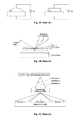
- FIGS. 1A , 1 B & 1 Cwhich depict several variants of the prior art, an illumination unit is usually combined with an electro-mechanical movement device such as scanning mirrors or rotating barriers (see U.S. Pat. Nos.
- volumetric aspectsThese methods need a distance between the light source and directional modulation device to work with, which increases the total volume of the display.
- Light lossCoupling light on to a moving mirror creates light losses which in turn degrades the display system power efficiency and creates heat that has to be eliminated by incorporating bulky cooling methods that add more volume and increased power consumption.
- the prior art directional backlight unitsneed to have narrow spectral bandwidth, high collimation and individual controllability for being combined with a directionally selective filter for 3D display purposes.
- Achieving narrow spectral bandwidth and high collimationrequires device level innovations and optical light conditioning, increasing the cost and the volumetric aspects of the overall display system.
- Achieving individual controllabilityrequires additional circuitry and multiple light sources increasing the system complexity, bulk and cost.
- U.S. patent application Ser. No. 13/329,107introduced a novel spatio-optical directional light modulator that overcomes most all of these drawbacks, however its angular coverage is limited by the numerical aperture of its light collimation optics.
- FIG. 1Aillustrates prior art directional light modulator that uses liquid lens.
- FIG. 1Billustrates prior art directional light modulator that uses scanning mirrors.
- FIG. 1Cillustrates prior art prior directionally modulated 3D light modulator.
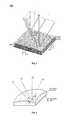
- FIG. 2illustrates an isometric view of the principle aspects of the spatio-temporal directional light modulator of this invention.
- FIG. 3illustrates the spatio-optical directional light modulation aspects of the spatio-temporal directional light modulator of this invention.
- FIG. 4Aillustrates the angular emission expansion made possible by the temporal articulation aspects of the spatio-temporal directional light modulator of this invention.
- FIG. 4Billustrates the angular temporal articulation of the spatio-temporal directional light modulator of this invention.
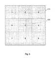
- FIG. 5illustrates the extended angular coverage cross section of the spatio-temporal directional light modulator of this invention.
- FIG. 6illustrates isometric, side and top views of one embodiment of the spatio-temporal directional light modulator of this invention.
- FIG. 7illustrates isometric, side and top views of another embodiment of the spatio-temporal directional light modulator of this invention.
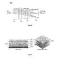
- FIG. 8Aillustrates an exemplary collimating wafer level optics design of the spatio-temporal directional light modulator of this invention.
- FIG. 8Billustrates an exemplary embodiment of the full assembly of the emissive micro emitter array device and the collimating wafer level optics of the spatio-temporal directional light modulator of this invention.
- FIG. 9Aillustrates an exemplary embodiment of directional addressability within one of the spatial modulation pixel groups of the spatio-temporal directional light modulator of this invention.
- FIG. 9Billustrates an exemplary embodiment of directional modulation within one of the spatial modulation pixel groups of the spatio-temporal directional light modulator of this invention.
- FIG. 10illustrates a block diagram explaining the data processing block diagram of the spatio-temporal directional light modulator of this invention.
- FIG. 11illustrates an isometric view of an exemplary embodiment of a 3D/2D switchable display implemented by tiling a multiplicity of the spatio-temporal directional light modulator of this invention.
- references in the following detailed description of the present invention to “one embodiment” or “an embodiment”means that a particular feature, structure, or characteristics described in connection with the embodiment is included in at least one embodiment of the invention.
- the appearances of the phrase “in one embodiment” in various places in this detailed descriptionare not necessarily all referring to the same embodiment.
- the SSL light emitting pixels of one such a devicemay be either a light emitting diode (LED) or laser diode (LD) whose on-off state is controlled by the drive circuitry contained within a CMOS chip (or device) upon which the emissive micro-scale pixel array is bonded.
- the size of the pixels comprising the emissive array of such deviceswould typically be in the range of approximately 5-20 micron with the typical emissive surface area of the device being in the range of approximately 15-150 square millimeter.
- the pixels within the emissive micro-scale pixel array deviceare individually addressable spatially, chromatically and temporally, typically through the drive circuitry of its CMOS chip.
- One example of such devicesare the QPI devices (see U.S. Pat. Nos. 7,623,560, 7,767,479, 7,829,902, 8,049,231, and 8,098,265, and U.S. Patent Application Publication Nos. 2010/0066921, 2012/0033113), referred to in the exemplary embodiments described below.
- Another example of such deviceis an OLED based micro-display.
- the QPI deviceis merely an example of the types of devices that may be used in the present invention.
- references to a QPI deviceare to be understood to be for purposes of specificity in the embodiments disclosed, and not for any limitation of the present invention.
- the present inventioncombines the emissive micro pixel array capabilities of the QPI device with passive wafer level optics (WLO) and an articulated movement of the entire assembly to create a light modulator that can perform the functionalities of a directional light source and a diffractive plate of the prior art at the same time.
- wafer level or wafermeans a device or matrix of devices having a diameter of at least 2 inches, and more preferably 4 inches or more.
- WLOare fabricated monolithically on the wafer from a polymer using ultra violet (UV) imprint lithography.
- WLOsmall feature micro lens arrays
- MLAsmall feature micro lens array
- the alignment precision that can be achieved by a typical WLO fabrication techniquecan be less than one micron.
- the combination of the individual pixel addressability of the emissive micro emitter pixel array of the QPI and the WLO micro lens array (MLA) that can be precisely aligned with respect to the micro emitter array of the QPIeliminates the need experienced in prior art for having a directionally selective filter in the system while relaxing the requirement for the narrow spectral bandwidth in the light source, reducing the system volume, complexity and cost simultaneously.
- directional modulation of the emitted lightis achieved by the combination of the light divergence achieved the WLO and the articulated movement of the entire assembly.
- FIG. 2conceptually illustrates spatio-temporal directional light modulator of this invention.
- the directional light modulator of this inventionis comprised of an emissive micro array QPI device 210 with a WLO micro lens array (MLA) 220 mounted directly on top of its emissive surface with the entire assembly being temporally articulated around at least one axis, and preferably around both its x and y axes by angles within the range of + ⁇ x and + ⁇ y ; respectively.
- the x-axis of the gimbalis temporally actuated by an angle within the range of + ⁇ x and the y-axis of the gimbal is temporally actuated by an angle within the range of ⁇ y .
- the x-axis and y-axis temporal articulation provided by the 2-axis gimbalwill cause the directional modulation angle of the light emitted from QPI/MLA assembly 230 to be temporally extended by 2 ⁇ x around the x direction and by 2 ⁇ y around the y direction beyond the angular extent provided by the micro lens elements of the MLA 220 (see FIG. 3 ).
- gimbal and two axis gimbalare used in the general sense, and mean any structure that will allow rotation, at least through a limited angle, about either or both any two orthogonal axes at any time.
- concentric rings, ball joints and any other structure that will provide that capabilityare included within the definition.
- each of the micro lens elements 310 comprising the 2-dimensional micro lens array MLA 220is the group of individually addressable QPI pixels (p 1 , p 2 , . . . , p n ) whereby the light emitted from each of the pixels in this group of pixels would be refracted into one of the unique directions (d 1 , d 2 , . . . , d n ) within the numerical aperture (angular extent) of their associated micro lens element.
- the entire micro-pixel array of the QPI device 210would comprise a multiplicity of QPI pixel groups (G 1 , G 2 , . . .
- each modulation group G iwould be associated with one of the 2-dimensional array MLA 220 lens elements and collectively the pixel modulation groups (G 1 , G 2 , . . . , G N ) would then represents the spatial modulation array of the spatio-temporal directional light modulator of this invention.
- the multiplicity of QPI pixel groups(G 1 , G 2 , . . .
- FIG. 4Awhich shows the temporal expansion of the QPI/MLA assembly 230 angular emission extent along one articulation axis, for the purpose of illustration.
- the angle ⁇represents the angular extent of one lens element of the MLA 220 and the angle ⁇ represents the composite instantaneous articulation angle of the lens element as a result of the gimbal articulation by the angles ⁇ x (t) and ⁇ y (t) around the x-axis and the y-axis; respectively.
- the articulation of QPI/MLA assembly 230as illustrated in FIG. 2 and explained by FIG.
- temporal articulation of the spatio-temporal directional light modulator 200 of this inventionwould temporally increase the modulated number of light directions (d 1 , d 2 , . . . , d n ) by the ratio of the angular extent expansion in each articulation direction expressed as ( ⁇ + ⁇ x )( ⁇ + ⁇ y )/ ⁇ 2 .
- the 2-axis articulation of the QPI/MLA assembly 230 of the spatio-temporal directional light modulator 200 of this inventioncan be in either temporally continuous or discrete (stepwise).
- FIG. 4Billustrates the composite temporal articulation angle ⁇ (t) of the QPI/MLA assembly 230 in one axis, for the purpose of illustration, when the articulation is temporally continuous 410 and when the actuation is temporally discrete 420 .
- the typical angular step sizewould preferably be proportional to the ratio of the angular extent ⁇ of the MLA 220 to spatial resolution the QPI/MLA assembly 230 .
- the temporal articulation of the QPI/MLA assembly 230 of the spatio-temporal directional light modulator of this inventionwould typically be a repetitive (or periodic) and independent around each of the 2-axis.
- the repetition periods of the articulation of the spatio-temporal light modulator of this inventionwould typically be proportional to and synchronized with display input data frame duration (for the purpose of reference, the image input data to a typical display arrives at 60 frames per second and is often referred to as 60 Hz frame rate input).
- the maximum values ⁇ xmax of the temporal articulation illustrated in FIG. 5would determine the expanded angular extent provided by the spatio-temporal light modulator which is determined by the value ⁇ ( ⁇ + ⁇ max ), where the angle ⁇ represents the angular extent of the lens elements of the MLA 220 .
- the periodicity of the x-axis and y-axis articulation collectivelywould typically be selected to enable temporal coverage of the desired expanded angular extent of the spatio-temporal light modulator 200 of this invention within a required display input frame rate.
- FIG. 5illustrates the angular coverage cross section 510 of the QPI/MLA assembly 230 of the spatio-temporal directional light modulator 200 of this invention being comprised of temporally multiplicity of the angular coverage cross section 520 of the MLA lens element.
- Appropriately selected temporal articulation ⁇ x (t) and ⁇ y (t) of the QPI/MLA assembly 230 around its x-axis and y-axis; respectively,will generate the angular coverage 510 that is comprised of multiplicity of temporally multiplexed angular coverage 520 of the MLA 210 lens element.
- the shape of the angular coverage cross section 510can be tailored in aspect ratio.
- the articulation rate around the x and y directionswould be sufficient to ensure that the temporally generated light directions within the angular coverage 510 have adequate duty cycle (modulation duration) within the modulation frame of the input image data.
- the modulation frame of the input image datais 60 image frames per second, which is typically referred to as 60 Hz image frame rate
- the articulation rate required to generate angular coverage illustrated in FIG. 5will need to be modulated once per frame, thus making the articulation rate required to generate angular coverage illustrated in FIG. 5 to be at least 180 Hz around either the x or the y axis.
- the articulation rate around either the x or the y directions for the illustration of FIG. 5would need to be at least three times the input image data frame rate.
- the angular coverage 520 of the MLA lens elementcan be either overlapping or non-overlapping.
- the articulation rate of the QPI/MLA assembly 230 around either the x or y axiswill have to be at least equal to the modulation frame rate of the input image data multiplied by a factor that equals to ratio of the size (in degrees) of the angular coverage 510 along each axis to the size (in degrees) of the angular coverage 520 along the same axis.
- the full emissive aperture of the QPI/MLA assembly 230would be utilized to accumulate (modulate) the desired intensity of the light beam (typically by pulse width modulation, though proportional control could be used if desired) at any given direction as that direction remains temporally within the coverage of the articulated aperture 510 .
- the response time of the spatio-temporal light modulator of this inventioncan be made to be commensurate with the image data input rate with minimal latency.
- the time duration a given direction remains within the angular coverage 520would determine the modulation time available for modulating the light intensity in that direction, and as a result, unless compensated, the directions within the peripheral area of the expanded angular coverage 510 could have less intensity than the interior region of the angular coverage 520 .
- This intensity edge tapering effectwould be somewhat similar to the Fresnel losses typically encountered at the edge of an optical system except in the case of the spatio-temporal light modulator of this invention, such an effect can be compensated by appropriate selection of the rate of the temporal articulation of the QPI/MLA assembly 230 of the spatio-temporal directional light modulator 200 of this invention.
- ⁇ xrepresents the angular extent (half angle) of one lens element around the x axis
- ⁇ yrepresents the angular extent of one lens element around the y axis
- the total angular extent, including the articulationwill be three times the angular extent of one micro lens element (3 times 2 ⁇ x or 3 times 2 ⁇ y ).
- these three contiguous angular extentswill be:
- each angular extentalso being constituting an angular increment in articulation.
- the three contiguous individual angular extents in each directioncan be considered as a two dimensional angular extent matrix as follows:
- This alternativeis a discrete technique, namely to display angular extent 1 for an allotted time, then advance around a first axis by one angular increment and then display angular extent 2 for the same allotted time, then advance one more angular increment and display angular extent 3 for the allotted time, then advance one angular increment on the other axis to display extent 6 for the allotted time, then go back one angular increment on that axis and display angular extent 5 for the allotted time, etc.
- angular extent 9is displayed for the allotted time, one could repeat 9 (continue displaying for twice the allotted time and then backtrack to avoid more than one angular increment in one axis at a time, though this would be expected to create a flicker unless a higher rate was used.
- a better approachwould be to go from angular extent 9 to angular extent 1 , a jump of two angular increments on 2 axes at the same time.
- FIG. 6One embodiment of this invention, herein referred to as 600 , is illustrated in FIG. 6 , which include an isometric, top view and side view illustrations of this embodiment.
- the spatio-temporal directional light modulator of this inventionis realized by bonding the QPI/MLA assembly 230 (depicted in FIG. 2 ) on the topside of the 2-axis gimbal assembly 620 which is fabricated using multiple silicon substrate layers; namely, a hinge layer 621 , a spacer layer 628 and a base layer 630 .
- FIG. 6illustrates the spatio-temporal directional light modulator of this invention.
- the hinge layer 621 of the 2-axis gimbal 620is comprised of an outer frame 622 , an inner ring 623 and the inner segment 625 upon which QPI/MLA assembly 230 would be bonded ( 625 is hereinafter also referred to synonymously as the device bonding pad 625 ).
- the gaps between the outer frame 622 , the inner ring 623 and the inner segment 625would be etched using standard semiconductor lithography techniques.
- the inner segment 625is physically connected along the x-axis to the inner ring 623 by two silicon bridges 622 , each typically approximately in the range of 0.3-0.5 mm wide, which would act as the x-axis hinge and would also to define the neutral x-axis position of the gimbal and act as a mechanical resistance spring for the x-axis articulation.
- the inner ring 623is connected along the y-axis to the outer frame 622 by two the silicon bridges 626 , each typically approximately in the range of 0.3-0.5 mm wide, which would act as the y-axis hinge and would also define the neutral y-axis position of the gimbal and act as a mechanical resistance spring for the y-axis articulation.
- the two pairs of silicon hinges 624 and 626constitute the pivot points of the 2-axis gimbal around which the x and y articulation would be performed.
- the interior segment 625 of the hinge layer 621 of the gimbal assembly 620contains multiplicity of contact pads to which the QPI/MLA assembly 230 will be bonded using standard soldering techniques such as flip chip solder balls, thus making the inner segment 625 become the bonding pad upon which QPI/MLA assembly 230 would be bonded.
- multiplicity of metal railswhich connect a set of contact pads on the topside of the interior segment 625 to a set of device contact pads 627 placed along the periphery of the outer frame 622 via the x-axis and y-axis hinge bridge areas 624 and 626 .
- the set of contact pads on the topside of the interior segment 625are the contact pads that would provide electrical and physical contact to the backside of the QPI/MLA assembly 230 .
- the QPI/MLA assembly 230is shown bonded to the topside of the interior segment 625 . As explained earlier, this would be both an electrical and physical contact bonding between the contact pads on the topside of the interior segment 625 and the contact pad at the backside of the QPI/MLA assembly 610 using solder or eutectic ball grid array type bonding. Also illustrated in FIG. 6 side view is the spacer layer 628 which would be bonded at wafer level with the base layer 630 topside and with the hinge layer backside using BenzoCycloButene (BCB) polymer adhesive bonding or the like.
- BCBBenzoCycloButene
- the height (or thickness) of the spacer layer 626would be selected to accommodate the vertical displacement of the corner of the hinged interior segment 625 together with the bonded QPI/MLA assembly 610 at the maximum actuation angle. For example, if the diagonal of the interior segment 625 together measures 5 mm and the maximum articulation angle at the corner is 15°, then the thickness of the spacer layer 626 should measure approximately 0.65 mm in order accommodate the vertical displacement of the corner of the hinged interior segment 625 at the maximum articulation.
- the articulation of the hinged interior segment 625 together with the bonded QPI/MLA assembly 230would be accomplished using a set of electromagnets 635 placed at the four corners of the backside of the hinged interior segment 625 , and a set of permanent magnets 636 placed on the topside of base layer 630 in alignment with the four corners of the backside of the hinged interior segment 625 .
- the electromagnets 635would be a coil having a metal core formed at wafer level using multilayer imprint lithography on the backside of the hinged interior segment 625 .
- the permanent magnets 636would be a thin magnetic strip typically of neodymium magnet (Nd 2 Fe 14 B) or the like.
- Articulation of the hinged interior segment 625 together with the bonded QPI/MLA assembly 230 as described earlierwould be accomplished by driving the set of electromagnets 635 with an electrical signal having the appropriate temporal amplitude variation to affect the appropriate temporal variation in the magnetic attraction between the set of electromagnets 635 and permanent magnets 636 that would cause of the hinged interior segment 625 together with the bonded QPI/MLA assembly 230 to be temporally articulated as described earlier.
- the drive electrical signals to the set of electromagnets 635which are generated by the QPI device 210 and supplied to the set of electromagnets 635 via the metal rails and contacts incorporated in the hinged interior segment 625 described earlier, would be made synchronous with the pixel modulation performed by the QPI device 210 to the extent that will enable the desired directional modulation of the intensity and color modulated light emitted from the pixel array of the QPI device 210 .
- the temporal variation of the drive electrical signals to the set of electromagnets 635would be selected to enable the temporal angular articulation of the hinged interior segment 625 together with the bonded QPI/MLA assembly 230 around both of their x-axis and y-axis as illustrated in FIG. 6 .
- the maximum value ⁇ max of the temporal angular articulation ⁇ (t) illustrated in FIG. 4B that can be achieved by embodiment 600 of this inventionwould typically be in the range from ⁇ 15° to ⁇ 17°.
- the drive electrical signals to the set of electromagnets 635which are generated by the QPI device 210 and supplied to the set of electromagnets 635 via the metal rails and contacts incorporated in the hinged interior segment 625 described earlier, would be comprised of a base component and a correction component.
- the base component of the drive electrical signals to the set of electromagnets 635would represent a nominal value and a correction component would be derived from an angular articulation error value generated by a set of four sensors positioned on the backside of the hinged interior segment 625 in alignment with the hinges 624 and 626 .
- sensorswould be an array of infrared (IR) detectors placed on the backside of the interior segment 625 in alignment with four IR emitters placed on the topside of the base layer 630 .
- the output values these four IR detector arrayswill be routed to the QPI device, again via the metal rails and contacts incorporated in the hinged interior segment 625 described earlier, and used to compute an estimate of the error between the derived and the actual articulation angle which will be incorporated as a correction to the drive signals provided by the QPI to the set of electromagnets 635 .
- the sensors positioned on the backside of the hinged interior segment 625could also be micro-scale gyros properly aligned to detect the actuation angle along each of the 2-axis of the gimbal.
- FIG. 7includes isometric views and side view illustrations of this embodiment.
- the embodiment 700 of this inventionis comprised of the 2-axis gimbal 720 with the QPI/MLA assembly 230 bonded on top of it.
- FIG. 7also shows an exploded isometric illustration of the embodiment 700 that shows the constituent layers of the 2-axis gimbal 720 of this embodiment.
- the spatio-temporal directional light modulator of this inventionis realized by bonding the QPI/MLA assembly 230 (depicted in FIG.
- the topside of the 2-axis gimbal assembly 720which is fabricated using multiple silicon substrate layers; namely, a pad layer 721 , a spring layer 725 and a base layer 730 .
- the topside of the pad layer 721incorporates a multiplicity of contact pads to which the QPI/MLA assembly 230 is to be bonded using standard soldering techniques such as flip chip solder balls, thus making the topside of the pad layer 721 being the bonding pad 723 upon which QPI/MLA assembly 230 would be bonded.
- the backside of the pad layer 721incorporates the spherical pivot 735 which would be formed by embossing polycarbonate polymer on the backside of the hinged pad layer 721 at the wafer level using UV imprint lithography or the like.
- the pad layer 712 together with the spherical pivot 735 embossed on its backsidewill be referred to as hinged pad 721 / 735 .
- the elevation of the center of the spherical pivot 735determines the elevation of the x and y axes of the angular deflection.
- the topside of the base layer 730incorporates the spherical socket 736 which would be formed by embossing of polycarbonate polymer on the topside of the base layer 730 at the wafer.
- the base layer 730 together with the spherical socket 736 embossed on its topsidewill be referred to as the pedestal 730 / 736 .
- the surface curvature the spherical pivot 735 incorporated on the backside of the pad layer 721 and the spherical socket 736 incorporated on the topside of the base layer 730will be ⁇ matched in order to allow the hinged pad 721 / 735 to make it a 2-axis articulated pad when placed on top of the pedestal 730 / 736 .
- embossed surfaces of the spherical pivot 735 and socket 736will be of optical quality in terms of surface roughness in the order of a few nm RMS, possible friction between the two surfaces due to the articulation movement would be reduced by coating the surfaces of the spherical pivot 735 and socket 736 with a thin layer (50-100 nm) of graphite.
- the hinged pad 721 / 735is retained in place within the surface curvature of the pedestal 730 / 736 by the spring layer 725 which contains at each of its four corners a single spiral shaped spring 726 that is etched into the spring layer 725 .
- the inner end of each of the four spiral shaped springsincorporates an inner bonding pad 727 which corresponds to an identical bonding pad 722 located at the backside of the pad layer 721 .
- Embedded within the spiral shaped springs 726are multiple metal rails that are used to route the electrical interface signals from its inner bonding pad 727 to a set of contact pads 728 located at the peripheral edge of the backside of the spring layer 725 .
- the edge contacts 728 on the backside of the outer end of the spring layer 725correspond to a matching set of bonding pads 729 that are located at the peripheral edge of the base layer 730 .
- the edge contacts on the topside of the base layer 730are connected via metal rails embedded within the base layer to a set of device contact pads 731 that are located on the backside of the base layer 730 .
- the four spiral shaped springs 726will be expanded when the backside bonding pads 726 of the spring layer 725 is bonded to the topside bonding pad 729 of the base layer 730 and the inner bonding pad 727 of the spiral spring 726 is bonded the corresponding bonding pad 722 on the backside of the pad layer 721 .
- the four spiral springs 726become fully expanded and in that full expanded configuration they serve the multiple purposes of: (1) creating a spring load resistance needed to retain the spherical pivot 735 within the spherical socket 736 ; (2) creating the mechanical balance needed for sustaining the neutral position of the hinged pad 721 / 735 ; and (3) routing the electrical interface signals from the device contact pads 731 to the contact pad 723 of the QPI/MLA assembly 230 .
- the QPI/MLA assembly 230is shown bonded to the topside contact pad 723 of the pad layer 721 .
- the extended height of the spherical socket 736which would be selected to accommodate the vertical displacement of the corner of the hinged pad 721 / 735 together with the bonded QPI/MLA assembly 230 at the maximum actuation angle.
- the thickness of the extended height of the spherical socket 736should measure approximately 1.25 mm in order accommodate the vertical displacement of the corner of the of the hinged pad 721 / 735 together with the bonded QPI/MLA assembly 710 at the maximum actuation angle.
- the actuation of the hinged pad 721 together with the bonded QPI/MLA assembly 230would be accomplished using a set of electromagnets embedded within the spherical pivot 735 and a set of permanent magnets embedded within the spherical socket 736 .
- the actuation electrical drive signalwould be routed to electromagnets embedded within the spherical pivot 735 in order to affect the actuation movement described in the earlier paragraphs.
- the base component of the actuation electrical drive signals to the electromagnets embedded within the spherical pivot 735would represent a nominal value and a correction component that would be derived from an angular articulation error value generated by a set of four sensors positioned on the backside of the hinged pad 721 .
- sensorsare an array of infrared (IR) detectors placed on the backside of the hinged pad 721 in alignment with four IR emitters placed on the topside of the base layer 730 .
- the output values these four IR detector arrayswill be routed to the QPI device, again via the metal rails and contacts incorporated in the hinged pad 721 described earlier, and used to compute an estimate of the error between the derived and the actual articulation angle which will be incorporated as a correction to the drive signals provided by the QPI device to the set of electromagnets embedded within the spherical pivot 735 .
- the sensors positioned on the backside of the hinged pad 721could also be micro-scale gyros properly aligned to detect the actuation angle along each of the 2-axis of the gimbal.
- the permanent magnets embedded within the spherical socket 736would be a thin magnetic rods or wires, typically of neodymium magnet (Nd 2 Fe 14 B) or the like, and would be shaped to provide a uniform magnetic field across the curved cavity of the spherical socket 736 .
- Actuation of the hinged pad 721 together with the bonded QPI/MLA assembly 230 as described earlierwould be accomplished by driving the set of electromagnets embedded within the spherical pivot 735 with an electrical signal having the appropriate temporal amplitude variation to affect the appropriate temporal variation in the magnetic attraction between the set of electromagnets embedded within the spherical pivot 735 and permanent magnets embedded within the spherical socket 736 that would cause of the hinged pad 721 together with the bonded QPI/MLA assembly 230 to be temporally articulated as described earlier.
- the drive electrical signals to the set of the set of electromagnets embedded within the spherical pivot 735which are generated by the QPI device and routed via the metal rails and contacts incorporated on the hinged pad 721 described earlier, would be made synchronous with the pixel modulation performed by the QPI device to an extent that will enable the desired directional modulation of the intensity and color modulated light emitted from the pixel array of the QPI device.
- the temporal variation of the drive electrical signals to the set of electromagnets embedded within the spherical pivot 735would be selected to enable the temporal angular articulation of the hinged pad 721 together with the bonded QPI/MLA assembly 230 along both of their x-axis and y-axis as illustrated in FIG.
- the maximum value ⁇ max of the temporal angular articulation ⁇ (t) illustrated in FIG. 6 that can be achieved by the embodiment 700 of this inventionwould typically be in the range from ⁇ 30° to ⁇ 35°.
- the two exemplary embodiments 600 and 700 of this inventiondiffer mainly in the maximum value ⁇ max of the temporal angular articulation ⁇ (t) each can achieve and in the outer area each embodiment needs beyond the boundary of the QPI/MLA assembly 230 .
- the 2-axis gimbalis fully accommodated within the footprint area of the QPI/MLA assembly 230 (hereinafter refer to a zero-edge feature) while as illustrated in FIG. 6 in the embodiment 600 of this invention the 2-axis gimbal is accommodated at the outer periphery of the QPI/MLA assembly 230 outer boundary.
- the maximum value ⁇ max of the temporal angular articulation ⁇ (t) embodiment 700can achieve could possibly be twice as large as what could be provided embodiment 600 .
- the larger maximum value ⁇ max of the temporal angular articulation ⁇ (t) that can be accomplished by the embodiment 700comes at the expense of requiring larger vertical height than the embodiment 600 .
- the zero-edge feature of the embodiment 700makes it more suitable for being tiled to create a large area display while the low profile (low height) feature of the embodiment 600 makes it more suitable for creating compact displays for mobile applications.
- FIG. 8Ashows an exemplary embodiment of one element of the MLA 220 and its associated pixel group G i of the QPI device 210 that can be used within the context of the present invention.
- the light emitted from each individual pixel within a pixel group G itravels from the QPI emissive surface to the exit aperture of a micro lens element that comprises the three optical elements 810 , 820 and 830 .
- the angular extent ⁇ of the MLA 220 micro lens system 810 , 820 and 830can be made either larger or smaller than the ⁇ 15° of the exemplary embodiment of FIG. 8A through appropriate design selection of the refracting surfaces of the micro lens system 810 , 820 and 830 or by increasing or decreasing the number of its optical elements. It should be noted, however, that for a given resolution in terms of number of pixels within the pixel modulation group G i , changing the angular extent ⁇ of the MLA 220 micro lens system would result in a change in the angular resolution (separation) between the directionally modulated light beams emitted by the QPI/MLA assembly 230 of the spatio-temporal directional light modulators of this invention.
- the maximum value of the articulation angle ⁇ maxcomes into the tradeoff as a parameter that can be used either to increase the angular extent of the directional modulation or the spatial resolution that can be achieved by the spatio-temporal directional modulators of this invention.
- FIG. 8Bshows an exemplary embodiment of the full assembly of the QPI/MLA assembly 230 of the spatio-temporal directional light modulators of this invention.
- the multiplicity of the micro lens elements 810 , 820 and 830are fabricated to form the micro lens arrays layers 840 , 850 and 860 which would be precisely aligned relative to each other and relative to the associated arrays of the QPI pixel groups (G 1 , G 2 , . . . , G N ).
- the exemplary embodiment illustrated in FIG. 8Balso includes the QPI device 210 and its associated cover glass 870 .
- the design of the micro lens elements 810 , 820 and 830would take into account the thickness and optical characteristics of the QPI cover glass 870 in order to image the emissive surface of the QPI device 210 .
- the exemplary embodiment of FIG. 8Billustrates the full assembly of the QPI/MLA assembly 230 that can be used within the context of the spatio-temporal directional light modulators of this invention.
- the typical total thickness of the embodiments 600 and 700 of the spatio-temporal directional light modulator of this inventionwould be less than 5 mm. Such compactness of the directional light modulator of this invention is not possibly achievable by directional light modulation techniques of the prior art.
- the spatio-temporal light modulators of this inventiondiffers in one very important aspect in that it generates, at any given instance of time, a multiplicity of light beams that are directionally modulated simultaneously.
- the multiplicity of directionally modulated light beamswould be temporally multiplexed by the articulation of the gimbaled QPI/MLA assembly 230 to expand the directional modulation resolution and angular extent.
- the response time the spatio-temporal light modulator of this inventioncan be made to be commensurate with the image data input rate with minimal latency.
- the articulation of the gimbaled QPI/MLA 230 QPI/MLA assembly 230 of the spatio-temporal directional light modulators of this inventioncan be made in a non-stop pattern that would result in minimal or no blanking of the emissive aperture of the gimbaled QPI/MLA 230 as it is articulated across the expanded angular extent of the spatio-temporal light modulators of this invention.
- the slow response time, poor efficiency and large volume drawbacks of prior art directional light modulatorsare all substantially overcome by the spatio-temporal light modulators of this invention.
- FIG. 9A and FIG. 9Billustrate the operational principles of the spatio-temporal directional light modulators of this invention.
- the directional modulation addressability that can be achieved by the pixel group G iwould be accomplished through the addressability of the (n ⁇ n) pixels comprising the modulation group G i along each of its two axes x and y using m-bit words.
- FIG. 9Aillustrates an exemplary embodiment of one of the pixel groups G i being comprised of a two dimensional array of (n ⁇ n) of the emissive pixels of the QPI device 210 whereby for convenience the size of the pixel group G i along one axis would be selected to be
- FIG. 9Billustrates the mapping of the light emitted from (n ⁇ n) pixels comprising the QPI pixel modulation group G i into individual directions within the three dimensional volume defined by angular extent ⁇ of the associated MLA 220 micro lens element such as that of the exemplary embodiment illustrated in FIG. 8A .
- the directional modulation angular extent provided by the lens elements of the QPI/MLA assembly 230will be temporally extended by the maximum articulation angle ⁇ max provided by the gimbal.
- the directional modulation angular extent provided by the spatio-temporal directional light modulator of this inventionwould be temporally extend over an angular coverage totaling ⁇ ( ⁇ + ⁇ max ).
- the number of light modulation directions that can be generated by the spatio-temporal directional light modulator of this inventionwould be (3n ⁇ 3n), where (n ⁇ n) is the size, in terms of number of QPI pixels, of the pixel groups G i associated with one of the MLA 220 lens elements.
- the spatio-temporal directional light modulator of this inventionwould offer an expanded directional modulation resolution to 9 ⁇ the directional modulation resolution provided by QPI/MLA assembly 230 .
- the directional modulation resolution provided by the spatio-temporal directional light modulators of this inventionwould [n( ⁇ + ⁇ max )/ ⁇ ] 2 within an angular extent that extends over an angle of ⁇ ( ⁇ + ⁇ max ).
- the light emitted from such a spatio-optical directional light modulator of this inventioncan be spatially modulated at a resolution of (16 ⁇ 16) and directionally modulated at a resolution of 147,456 within the angular extent ⁇ 45°, and can also be modulated in color and intensity in each direction.
- the spatial and directional modulation resolutions of the spatio-temporal light modulator of this invention in terms of the number of individually addressable directions within a given the angular extentwould be determined by selecting the resolution and pixel pitch of the emissive micro emitter array QPI device 210 , the pitch of the MLA 220 lens elements, the angular extent of the MLA 220 lens elements and the maximum articulation angle of the modulator gimbal.
- the MLA lens systemcan be designed to allow either wider or narrower angular extent
- the gimbal designcan be selected to allow either wider or narrower articulation angle
- the number of pixels within each modulation groupcan be selected either smaller or larger in order to create a spatio-temporal directional light modulator that can achieve any desired spatial and directional modulation capabilities following the teachings provided in the preceding discussion.
- any desired spatial and directional modulation capabilitiescan be realized using the spatio-optical directional light modulators of this invention.
- the previous exampleillustrated how a spatio-optical directional light modulator of this invention with (16) 2 spatial resolution and (3 ⁇ 128) 2 directional resolution can be implemented using a single 10.24 ⁇ 10.24 mm QPI device 210 .
- the spatio-temporal directional light modulator of this inventioncan be implemented using a tiled array comprising multiplicity of smaller spatial resolution spatio-temporal directional light modulator of this invention. For example, when an array of (3 ⁇ 3) of the spatio-temporal directional light modulator of the previous example are tiled as illustrated in FIG.
- the resultant spatio-temporal directional light modulatorswould provide (3 ⁇ 16) 2 spatial resolution and (3 ⁇ 128) 2 directional resolution.
- the tiling of a multiplicity of the spatio-temporal directional modulator of this invention in order to realize a higher spatial resolution versionis possible because of its compact volumetric dimensions.
- the spatio-temporal directional light modulator of the previous example that uses a single QPI device 210which by itself would have an exemplary width, height and thickness of 10.24 ⁇ 10.24 ⁇ 5 mm; respectively, can be used to create the larger resolution version illustrated in FIG. 10 which would have the dimension of 3.07 ⁇ 3.07 ⁇ 0.5 cm in width, height and thickness; respectively.
- the resultant spatio-temporal directional light modulatorwould have a (30 ⁇ 16) 2 spatial resolution and (3 ⁇ 128) 2 directional resolution and would measure 30.07 ⁇ 30.07 ⁇ 0.5 cm in width, height and thickness, respectively. It would be possible to implement the higher spatial resolution version of the spatio-temporal directional light modulator of this invention illustrated is FIG.
- the (3 ⁇ 3) array illustrated in FIG. 10would provide (3 ⁇ 32) 2 spatial resolution and (3 ⁇ 64) 2 directional resolution. It is worth noting that the array of spatio-temporal directional light modulators which offers the expanded spatial aperture illustrated in FIG. 10 is made possible by the zero-edge feature described earlier of the spatio-temporal directional light modulator embodiment 700 of this invention.
- FIG. 9Aillustrates the two dimensional addressability of each of the modulation group G i using m-bit resolution for the directional modulation.
- light emitted from (2 m ⁇ 2 m ) individual pixels of the modulation group G iis mapped by its associated MLA 220 elements into 2 2m light directions within the angular extent ⁇ of the associated MLA micro lens element.
- the angular coordinates ( ⁇ , ⁇ ) of the emitted light beamis given by:
- the spatial resolution of the spatio-temporal directional light modulator of this inventionis defined the coordinates (X, Y) of each of the individual modulation group G i within the two dimensional array of modulation groups comprising the overall spatio-temporal directional light modulator.
- the spatio-temporal light modulator of this inventionwould be capable of temporally generating (modulating) a light field described by the spatial coordinates (X, Y) defined by its modulation group array and the directional coordinates ( ⁇ , ⁇ ) with the latter being defined by the values of the coordinates (x, y) of the emissive pixels within the modulation group G i and the temporal value of the articulation angle of the spatio-temporal directional light modulator as defined by Eq. 1 and 2 above.
- FIG. 11illustrates an exemplary embodiment of the data processing block diagram of the spatio-temporal directional light modulator of this invention.
- the input data to the spatio-temporal directional light modulator of this inventionwill be formatted in multiple bit words whereby each input word contains the three data fields; one field being the address of modulation group G i within the modulation group array comprising the spatio-optical directional light modulator while the remaining two data fields provide the data representation of the light to be emitted from that modulation group in terms of its color, intensity and direction.
- the data processing block 120decodes the modulation group address field of the input data and route the light modulation data fields to the QPI device associated with the designated modulation group.
- the data processing block 130decodes the routed modulation group address field and maps it to the address of the designated modulation group.
- the data processing block 140decodes the directional modulation data field and maps it into the address of designated pixel address within the modulation group.
- the data processing block 150concatenates the resultant pixel address with the associated light intensity and color data fields of the input data.
- the data processing block 160decodes the designated pixel address and routes the light modulation data to the designated pixel within the designated QPI device comprising the spatio-optical directional light modulator.
- the total number bits that would represent the modulation data word for each modulation groupwould be 40-bit.
- block 120 of FIG. 11would be responsible for routing the sequentially inputted data word to the designated QPI device.
- Block 130 of FIG. 11would be responsible for routing the modulation data to the designated modulation group.
- Block 11would be responsible for mapping the 16-bit directional modulation data field into the designated address of the pixel with the designated modulation group.
- Block 150 of FIG. 10would be responsible for concatenating the 24-bit light intensity and color data with the mapped pixel group address.
- Block 160 of FIG. 11would be responsible for routing the 24-bit light intensity and color modulation data to the designated pixel within the designated QPI device comprising the spatio-temporal directional light modulator.
- the spatio-temporal directional light modulator of this inventionwould modulate the light emitted from its aperture in intensity, color and direction based on the information encoded within its input data.
- the spatio-temporal directional light modulator of this inventioncan be used to implement a 3D display with an arbitrary size that is realized, for example, as a tiled array of multiplicity of spatio-temporal directional light modulator devices such as that illustrated in FIG. 10 .
- the expanded angular extent that can be realize by the spatio-temporal directional light modulator of this inventionwould enable the realization of 3D displays that are volumetrically compact and provide a large viewing angle, yet without the use of bulky and costly optical assemblies.
- the level of volumetric compactness that can be achieved by the spatio-temporal directional light modulator of this inventionwill enable the realization of both desk top as well as possibly mobile 3D displays.
- the expanded directional modulation capabilities of the spatio-temporal directional light modulator of this inventionmakes it capable of modulating within its expanded angular extent a multiplicity of views with an angular resolution value of ⁇ that is commensurate with the human visual system eye angular separation, thus making it a 3D display that will not require the use of glasses to view the 3D content it display.
- the spatio-temporal directional light modulator of this inventioncan generate, it would be capable of modulating a 3D image with sufficient angular resolution value between the generated multiple views that will eliminate the vergence-accommodation conflict (VAC) which typically hinders the performance of 3D displays and cause visual fatigue.
- VACvergence-accommodation conflict
- the angular resolution capabilities of the spatio-temporal directional light modulator of this inventionmake it capable of generating a VAC-free 3D images that will not cause viewers' visual fatigue.
- the light field modulation capabilities of the spatio-temporal directional light modulator of this inventionalso makes it the underlying bases of a 3D light field display that can be used to implement a synthetic holography 3D displays.
- the spatio-temporal directional light modulator of this inventioncan also be used as a backlight for liquid crystal display (LCD) to implement a 3D display.
- the spatio-temporal directional light modulator of this inventioncan also be operated as a 2D high resolution display. In this case the individual pixels of the QPI device 210 would be used to modulate the color and intensity while the MLA 220 would be used to fill the viewing angle of the display. It is also possible for the spatio-temporal light modulator of this invention to be switched from 2D to 3D display modes by adapting the format of its input data to be commensurate with the desired operational mode.
- the spatio-temporal directional light modulator of this inventionWhen the spatio-temporal directional light modulator of this invention is used as a 2D display its light angular extent will be that of associate with its MLA 220 micro lens element plus the articulation angle of its gimbal ⁇ ( ⁇ + ⁇ max ) with the pixel resolution of the individual modulation group G i leveraged to achieve higher spatial resolution.
Landscapes
- Physics & Mathematics (AREA)
- General Physics & Mathematics (AREA)
- Optics & Photonics (AREA)
- Engineering & Computer Science (AREA)
- Multimedia (AREA)
- Signal Processing (AREA)
- Mechanical Light Control Or Optical Switches (AREA)
Abstract
Description
- This application claims the benefit of U.S. Provisional Patent Application No. 61/616,249 filed Mar. 27, 2012.
- 1. Field of the Invention
- The present invention relates to the field of directional light modulation, 3D displays, emissive micro displays, 2D/3D switchable displays.
- 2. Prior Art
- In 3D displays, directional modulation of the emitted light is necessary to create the 3D viewing perception. In a typical 3D display, a backlight with uniform illumination in multiple illumination directions is required to display images of the same scene from different directions by utilizing some combination of spatial multiplexing and temporal multiplexing in the spatial light modulator. In these 3D displays the light that typically comes from the directional backlight is usually processed by a directionally selective filter (such as diffractive plate or a holographic optical plate for example) before it reaches the spatial light modulator pixels that modulate the light color and intensity while keeping its directionality.
- Currently available directional light modulators are a combination of an illumination unit comprising multiple light sources and a directional modulation unit that directs the light emitted from the light sources to a designated direction (see
FIGS. 1A ,1B &1C). As illustrated inFIGS. 1A ,1B &1C which depict several variants of the prior art, an illumination unit is usually combined with an electro-mechanical movement device such as scanning mirrors or rotating barriers (see U.S. Pat. Nos. 6,151,167, 6,433,907, 6,795,221, 6,803,561, 6,924,476, 6,937,221, 7,061,450, 7,071,594, 7,190,329, 7,193,758, 7,209,271, 7,232,071, 7,482,730, 7,486,255, 7,580,007, 7,724,210 and 7,791,810, and U.S. Patent Application Publication Nos. 2010/0026960 and 2010/0245957, or electro-optically such as liquid lenses or polarization switching (seeFIGS. 1A ,1B &1C and U.S. Pat. Nos. 5,986,811, 6,999,238, 7,106,519, 7,215,475, 7,369,321, 7,619,807 and 7,952,809). - In both electro-mechanically and electro-optically modulated directional light modulators there are three main drawbacks:
- 1. Response time: The mechanical movement or optical surface change are typically not achieved instantaneously and affect the modulator response time. In addition, the speed of these operations usually takes up some portion of the image frame time that reduces the achievable display brightness.
- 2. Volumetric aspects: These methods need a distance between the light source and directional modulation device to work with, which increases the total volume of the display.
- 3. Light loss: Coupling light on to a moving mirror creates light losses which in turn degrades the display system power efficiency and creates heat that has to be eliminated by incorporating bulky cooling methods that add more volume and increased power consumption.
- In addition to being slow, bulky and optically lossy, the prior art directional backlight units need to have narrow spectral bandwidth, high collimation and individual controllability for being combined with a directionally selective filter for 3D display purposes. Achieving narrow spectral bandwidth and high collimation requires device level innovations and optical light conditioning, increasing the cost and the volumetric aspects of the overall display system. Achieving individual controllability requires additional circuitry and multiple light sources increasing the system complexity, bulk and cost. U.S. patent application Ser. No. 13/329,107 introduced a novel spatio-optical directional light modulator that overcomes most all of these drawbacks, however its angular coverage is limited by the numerical aperture of its light collimation optics.
- It is therefore an objective of this invention to introduce an extended angular coverage spatio-temporal light modulator that overcomes the limitation of the prior art, thus making it feasible to create 3D and high resolution 2D displays that provide the volumetric advantages plus a viewing experience over a wide viewing angle. Additional objectives and advantages of this invention will become apparent from the following detailed description of a preferred embodiment thereof that proceeds with reference to the accompanying drawings.
FIG. 1A illustrates prior art directional light modulator that uses liquid lens.FIG. 1B illustrates prior art directional light modulator that uses scanning mirrors.FIG. 1C illustrates prior art prior directionally modulated 3D light modulator.FIG. 2 illustrates an isometric view of the principle aspects of the spatio-temporal directional light modulator of this invention.FIG. 3 illustrates the spatio-optical directional light modulation aspects of the spatio-temporal directional light modulator of this invention.FIG. 4A illustrates the angular emission expansion made possible by the temporal articulation aspects of the spatio-temporal directional light modulator of this invention.FIG. 4B illustrates the angular temporal articulation of the spatio-temporal directional light modulator of this invention.FIG. 5 illustrates the extended angular coverage cross section of the spatio-temporal directional light modulator of this invention.FIG. 6 illustrates isometric, side and top views of one embodiment of the spatio-temporal directional light modulator of this invention.FIG. 7 illustrates isometric, side and top views of another embodiment of the spatio-temporal directional light modulator of this invention.FIG. 8A illustrates an exemplary collimating wafer level optics design of the spatio-temporal directional light modulator of this invention.FIG. 8B illustrates an exemplary embodiment of the full assembly of the emissive micro emitter array device and the collimating wafer level optics of the spatio-temporal directional light modulator of this invention.FIG. 9A illustrates an exemplary embodiment of directional addressability within one of the spatial modulation pixel groups of the spatio-temporal directional light modulator of this invention.FIG. 9B illustrates an exemplary embodiment of directional modulation within one of the spatial modulation pixel groups of the spatio-temporal directional light modulator of this invention.FIG. 10 illustrates a block diagram explaining the data processing block diagram of the spatio-temporal directional light modulator of this invention.FIG. 11 illustrates an isometric view of an exemplary embodiment of a 3D/2D switchable display implemented by tiling a multiplicity of the spatio-temporal directional light modulator of this invention.- References in the following detailed description of the present invention to “one embodiment” or “an embodiment” means that a particular feature, structure, or characteristics described in connection with the embodiment is included in at least one embodiment of the invention. The appearances of the phrase “in one embodiment” in various places in this detailed description are not necessarily all referring to the same embodiment.
- A new class of emissive micro-scale pixel array devices has been recently introduced These devices feature high brightness, very fast light multi-color intensity and spatial modulation capabilities in a very small single device size that includes all the drive circuitry. The SSL light emitting pixels of one such a device may be either a light emitting diode (LED) or laser diode (LD) whose on-off state is controlled by the drive circuitry contained within a CMOS chip (or device) upon which the emissive micro-scale pixel array is bonded. The size of the pixels comprising the emissive array of such devices would typically be in the range of approximately 5-20 micron with the typical emissive surface area of the device being in the range of approximately 15-150 square millimeter. The pixels within the emissive micro-scale pixel array device are individually addressable spatially, chromatically and temporally, typically through the drive circuitry of its CMOS chip. One example of such devices are the QPI devices (see U.S. Pat. Nos. 7,623,560, 7,767,479, 7,829,902, 8,049,231, and 8,098,265, and U.S. Patent Application Publication Nos. 2010/0066921, 2012/0033113), referred to in the exemplary embodiments described below. Another example of such device is an OLED based micro-display. However it is to be understood that the QPI device is merely an example of the types of devices that may be used in the present invention. Thus in the description to follow, references to a QPI device are to be understood to be for purposes of specificity in the embodiments disclosed, and not for any limitation of the present invention.
- The present invention combines the emissive micro pixel array capabilities of the QPI device with passive wafer level optics (WLO) and an articulated movement of the entire assembly to create a light modulator that can perform the functionalities of a directional light source and a diffractive plate of the prior art at the same time. As used herein, wafer level or wafer means a device or matrix of devices having a diameter of at least 2 inches, and more preferably 4 inches or more. WLO are fabricated monolithically on the wafer from a polymer using ultra violet (UV) imprint lithography. Among primary advantages of WLO are the ability to fabricate small feature micro lens arrays (MLA) and to be able to precisely align multiple WLO micro lens array layers together and with an optoelectronics device such as a CMOS sensor or the QPI. The alignment precision that can be achieved by a typical WLO fabrication technique can be less than one micron. The combination of the individual pixel addressability of the emissive micro emitter pixel array of the QPI and the WLO micro lens array (MLA) that can be precisely aligned with respect to the micro emitter array of the QPI eliminates the need experienced in prior art for having a directionally selective filter in the system while relaxing the requirement for the narrow spectral bandwidth in the light source, reducing the system volume, complexity and cost simultaneously. In this invention directional modulation of the emitted light is achieved by the combination of the light divergence achieved the WLO and the articulated movement of the entire assembly.
FIG. 2 conceptually illustrates spatio-temporal directional light modulator of this invention. As illustrated inFIG. 2 , the directional light modulator of this invention is comprised of an emissive microarray QPI device 210 with a WLO micro lens array (MLA)220 mounted directly on top of its emissive surface with the entire assembly being temporally articulated around at least one axis, and preferably around both its x and y axes by angles within the range of +αxand +αy; respectively. The articulation of the QPI/MLA assembly 230 as illustrated inFIG. 2 would be accomplished by placing the entire assembly on a 2-axis gimbal whereby the x-axis of the gimbal is temporally actuated by an angle within the range of +αxand the y-axis of the gimbal is temporally actuated by an angle within the range of ±αy. The x-axis and y-axis temporal articulation provided by the 2-axis gimbal will cause the directional modulation angle of the light emitted from QPI/MLA assembly 230 to be temporally extended by 2αxaround the x direction and by 2αyaround the y direction beyond the angular extent provided by the micro lens elements of the MLA220 (seeFIG. 3 ). As used herein, the words gimbal and two axis gimbal are used in the general sense, and mean any structure that will allow rotation, at least through a limited angle, about either or both any two orthogonal axes at any time. Thus concentric rings, ball joints and any other structure that will provide that capability are included within the definition.- Referring to
FIG. 3 , associated with each of the micro lens elements310 comprising the 2-dimensional microlens array MLA 220 is the group of individually addressable QPI pixels (p1, p2, . . . , pn) whereby the light emitted from each of the pixels in this group of pixels would be refracted into one of the unique directions (d1, d2, . . . , dn) within the numerical aperture (angular extent) of their associated micro lens element. The entire micro-pixel array of theQPI device 210 would comprise a multiplicity of QPI pixel groups (G1, G2, . . . , GN), herein also referred to as pixel modulation groups, whereby each modulation group Giwould be associated with one of the 2-dimensional array MLA 220 lens elements and collectively the pixel modulation groups (G1, G2, . . . , GN) would then represents the spatial modulation array of the spatio-temporal directional light modulator of this invention. With the temporal articulation illustrated inFIG. 2 and the one-to-one association of the individual pixels (p1, p2, . . . , pn) within each pixel group and the emitted light directions (d1, d2, . . . , dn), it becomes possible for the spatio-temporal directional light modulator of this invention conceptually illustrated inFIG. 2 to have associated with each of its pixel groups Gia multiplicity of temporally multiplexed directions (d1i, d2i, . . . , dni); i=1, 2, . . . , each being individually addressable by temporal addressing of the individual pixels (p1, p2, . . . , pn) within each of the pixel groups (G1, G2, . . . , GN). The multiplicity of QPI pixel groups (G1, G2, . . . , GN) associated with the 2-dimensional array MLA 220 ofFIG. 2 would then represent the spatial modulation array of the spatio-temporal directional light modulator of this invention with the temporally multiplexed directions (d1i, d2i, . . . , dni); i=1, 2, . . . , representing the multiplicity of light modulation directions individually addressable through temporal addressability of the pixels (p1, p2, . . . , pn) of theQPI device 210 comprising each pixel modulation group. In other words, the spatio-temporal directional light modulator of this invention would be able to spatially modulate light through addressability of the QPI pixel groups (G1, G2, . . . , GN) and directionally modulate the light emitted from each pixel group in the directions (d1i, d2i, . . . , dni); i=1, 2, . . . , through temporal addressability of the pixels (p1, p2, . . . , pn) comprising each group. Therefore, the spatio-temporal directional light modulator of this invention illustrated inFIG. 2 would be able to generate light that can be spatially and directionally modulated whereby the light emitted from each of the spatial locations that equals the emissive area of the QPI pixel groups (G1, G2, . . . , GN) is individually addressable through the addressability of the pixel groups as well as being directionally addressable through the temporal addressability of the individual pixel within each pixel group. - The x-axis and y-axis articulation of QPI/
MLA assembly 230 as illustrated inFIG. 2 will cause the light emitted in the directions (d1, d2, . . . , dn) to be temporally multiplexed into the multiplicity of light directions (d1i, d2i, . . . , dni); i=1, 2, . . . , which extend over the angular extent provided by the lens elements of theMLA 220 plus 2αxin the x direction and by 2αyin the y directions. This is illustrated inFIG. 4A which shows the temporal expansion of the QPI/MLA assembly 230 angular emission extent along one articulation axis, for the purpose of illustration. Referring toFIG. 4A , the angle Θ represents the angular extent of one lens element of theMLA 220 and the angle α represents the composite instantaneous articulation angle of the lens element as a result of the gimbal articulation by the angles αx(t) and αy(t) around the x-axis and the y-axis; respectively. The articulation of QPI/MLA assembly 230 as illustrated inFIG. 2 and explained byFIG. 4A enable the pixels within emissive micro-scale array of theQPI device 210, which are individually addressable through the QPI drive circuitry, to emit light that is modulated both spatially, chromatically and directionally whereby the angular extent of the directionally modulated light is temporally expanded by an angle2αxin the x direction and by an angle2αyin the y direction beyond the angular extent Θ (or numerical aperture) of the lens elements of theMLA 220. Furthermore, temporal articulation of the spatio-temporal directionallight modulator 200 of this invention would temporally increase the modulated number of light directions (d1, d2, . . . , dn) by the ratio of the angular extent expansion in each articulation direction expressed as (Θ+αx)(Θ+αy)/Θ2. - The 2-axis articulation of the QPI/
MLA assembly 230 of the spatio-temporal directionallight modulator 200 of this invention can be in either temporally continuous or discrete (stepwise).FIG. 4B illustrates the composite temporal articulation angle α(t) of the QPI/MLA assembly 230 in one axis, for the purpose of illustration, when the articulation is temporally continuous410 and when the actuation is temporally discrete420. When the temporal articulation of the spatio-temporal directionallight modulator 200 of this invention is discrete or stepwise (420), the typical angular step size would preferably be proportional to the ratio of the angular extent Θ of theMLA 220 to spatial resolution the QPI/MLA assembly 230. As illustrated inFIG. 5 , the temporal articulation of the QPI/MLA assembly 230 of the spatio-temporal directional light modulator of this invention would typically be a repetitive (or periodic) and independent around each of the 2-axis. The repetition periods of the articulation of the spatio-temporal light modulator of this invention would typically be proportional to and synchronized with display input data frame duration (for the purpose of reference, the image input data to a typical display arrives at 60 frames per second and is often referred to as 60 Hz frame rate input). The maximum values ±αxmaxof the temporal articulation illustrated inFIG. 5 would determine the expanded angular extent provided by the spatio-temporal light modulator which is determined by the value ±(Θ+αmax), where the angle Θ represents the angular extent of the lens elements of theMLA 220. The periodicity of the x-axis and y-axis articulation collectively would typically be selected to enable temporal coverage of the desired expanded angular extent of the spatio-temporal light modulator 200 of this invention within a required display input frame rate. FIG. 5 illustrates the angularcoverage cross section 510 of the QPI/MLA assembly 230 of the spatio-temporal directionallight modulator 200 of this invention being comprised of temporally multiplicity of the angularcoverage cross section 520 of the MLA lens element. Appropriately selected temporal articulation αx(t) and αy(t) of the QPI/MLA assembly 230 around its x-axis and y-axis; respectively, will generate theangular coverage 510 that is comprised of multiplicity of temporally multiplexedangular coverage 520 of theMLA 210 lens element. Depending on the magnitude of the angular articulation αxand αyof the QPI/MLA assembly 230 around their x and y axes, the shape of the angularcoverage cross section 510 can be tailored in aspect ratio. The articulation rate around the x and y directions would be sufficient to ensure that the temporally generated light directions within theangular coverage 510 have adequate duty cycle (modulation duration) within the modulation frame of the input image data. For example, when the modulation frame of the input image data is60 image frames per second, which is typically referred to as 60 Hz image frame rate, each of the light directions within each of the temporalangular coverage 520 illustrated inFIG. 5 will need to be modulated once per frame, thus making the articulation rate required to generate angular coverage illustrated inFIG. 5 to be at least 180 Hz around either the x or the y axis. In other words, for the angular coverage example illustrated inFIG. 5 where the size of the temporalangular coverage 510 is three times the size ofangular coverage 520 in each axis, the articulation rate around either the x or the y directions for the illustration ofFIG. 5 would need to be at least three times the input image data frame rate. Theangular coverage 520 of the MLA lens element can be either overlapping or non-overlapping. In general the articulation rate of the QPI/MLA assembly 230 around either the x or y axis will have to be at least equal to the modulation frame rate of the input image data multiplied by a factor that equals to ratio of the size (in degrees) of theangular coverage 510 along each axis to the size (in degrees) of theangular coverage 520 along the same axis.- Referring to
FIG. 5 , with the temporal articulation of the QPI/MLA assembly 230 of the spatio-temporal directionallight modulator 200 of this invention having theangular coverage 520 and comprising the multiplicity of the directionally modulated light emitted corresponding with the multiplicity of pixels comprising theQPI device 210, a new set of directionally modulated light beams would be continuously added as some drop off temporally in a pipeline fashion until the expandedangular extent 510 of the spatio-temporal directionallight modulator 200 of this invention is fully covered. At any given instant the full emissive aperture of the QPI/MLA assembly 230 would be utilized to accumulate (modulate) the desired intensity of the light beam (typically by pulse width modulation, though proportional control could be used if desired) at any given direction as that direction remains temporally within the coverage of the articulatedaperture 510. As a result of this spatio-temporal pipelining of the multiplicity of the directionally modulated light beams, the response time of the spatio-temporal light modulator of this invention can be made to be commensurate with the image data input rate with minimal latency. The time duration a given direction remains within theangular coverage 520 would determine the modulation time available for modulating the light intensity in that direction, and as a result, unless compensated, the directions within the peripheral area of the expandedangular coverage 510 could have less intensity than the interior region of theangular coverage 520. This intensity edge tapering effect would be somewhat similar to the Fresnel losses typically encountered at the edge of an optical system except in the case of the spatio-temporal light modulator of this invention, such an effect can be compensated by appropriate selection of the rate of the temporal articulation of the QPI/MLA assembly 230 of the spatio-temporal directionallight modulator 200 of this invention. - As an alternative, using the 3×3 example again, if Θxrepresents the angular extent (half angle) of one lens element around the x axis and Θyrepresents the angular extent of one lens element around the y axis and if αxequals 2Θxand αyequals 2Θy, the total angular extent, including the articulation, will be three times the angular extent of one micro lens element (3 times 2Θxor 3 times 2Θy). By way of example, for the x axis, these three contiguous angular extents will be:
- (−αx−Θ0x) to (−Θx)
- (−Θx) to (Θx), and
- (Θx) to (Θx+αx)
- each angular extent also being constituting an angular increment in articulation.
- The three contiguous individual angular extents in each direction can be considered as a two dimensional angular extent matrix as follows:
- 1, 2, 3
- 4, 5, 6
- 7, 8, 9
- This alternative is a discrete technique, namely to display
angular extent 1 for an allotted time, then advance around a first axis by one angular increment and then displayangular extent 2 for the same allotted time, then advance one more angular increment and displayangular extent 3 for the allotted time, then advance one angular increment on the other axis to displayextent 6 for the allotted time, then go back one angular increment on that axis and displayangular extent 5 for the allotted time, etc. Afterangular extent 9 is displayed for the allotted time, one could repeat9 (continue displaying for twice the allotted time and then backtrack to avoid more than one angular increment in one axis at a time, though this would be expected to create a flicker unless a higher rate was used. A better approach would be to go fromangular extent 9 toangular extent 1, a jump of two angular increments on2 axes at the same time. However a jump of two angular increments on2 axes should not take twice as long as an angular change of one angular increment on one axis, as the x and y axes will be independent of each other, and any change comprises an angular acceleration followed by an angular deceleration, so the average velocity is higher for a change of two angular increments than for a change of one angular increment. Still further alternatives might include a combination of discrete and continuous techniques. The point is that there are many alternatives one could choose from, all of which are within the scope of the present invention. - One embodiment of this invention, herein referred to as600, is illustrated in
FIG. 6 , which include an isometric, top view and side view illustrations of this embodiment. As illustrated inFIG. 6 , the spatio-temporal directional light modulator of this invention is realized by bonding the QPI/MLA assembly230 (depicted inFIG. 2 ) on the topside of the 2-axis gimbal assembly620 which is fabricated using multiple silicon substrate layers; namely, a hinge layer621, a spacer layer628 and a base layer630. As illustrated inFIG. 6 , the hinge layer621 of the 2-axis gimbal620 is comprised of an outer frame622, an inner ring623 and the inner segment625 upon which QPI/MLA assembly 230 would be bonded (625 is hereinafter also referred to synonymously as the device bonding pad625). The gaps between the outer frame622, the inner ring623 and the inner segment625 would be etched using standard semiconductor lithography techniques. The inner segment625 is physically connected along the x-axis to the inner ring623 by two silicon bridges622, each typically approximately in the range of 0.3-0.5 mm wide, which would act as the x-axis hinge and would also to define the neutral x-axis position of the gimbal and act as a mechanical resistance spring for the x-axis articulation. The inner ring623 is connected along the y-axis to the outer frame622 by two the silicon bridges626, each typically approximately in the range of 0.3-0.5 mm wide, which would act as the y-axis hinge and would also define the neutral y-axis position of the gimbal and act as a mechanical resistance spring for the y-axis articulation. The two pairs of silicon hinges624 and626 constitute the pivot points of the 2-axis gimbal around which the x and y articulation would be performed. The interior segment625 of the hinge layer621 of the gimbal assembly620 contains multiplicity of contact pads to which the QPI/MLA assembly 230 will be bonded using standard soldering techniques such as flip chip solder balls, thus making the inner segment625 become the bonding pad upon which QPI/MLA assembly 230 would be bonded. Embedded within the interior segment625 of the hinge layer621 of the gimbal assembly620 are multiplicity of metal rails which connect a set of contact pads on the topside of the interior segment625 to a set of device contact pads627 placed along the periphery of the outer frame622 via the x-axis and y-axis hinge bridge areas624 and626. The set of contact pads on the topside of the interior segment625 are the contact pads that would provide electrical and physical contact to the backside of the QPI/MLA assembly 230. - Referring to the side view illustration of
FIG. 6 , the QPI/MLA assembly 230 is shown bonded to the topside of the interior segment625. As explained earlier, this would be both an electrical and physical contact bonding between the contact pads on the topside of the interior segment625 and the contact pad at the backside of the QPI/MLA assembly610 using solder or eutectic ball grid array type bonding. Also illustrated inFIG. 6 side view is the spacer layer628 which would be bonded at wafer level with the base layer630 topside and with the hinge layer backside using BenzoCycloButene (BCB) polymer adhesive bonding or the like. The height (or thickness) of the spacer layer626 would be selected to accommodate the vertical displacement of the corner of the hinged interior segment625 together with the bonded QPI/MLA assembly610 at the maximum actuation angle. For example, if the diagonal of the interior segment625 together measures 5 mm and the maximum articulation angle at the corner is 15°, then the thickness of the spacer layer626 should measure approximately 0.65 mm in order accommodate the vertical displacement of the corner of the hinged interior segment625 at the maximum articulation. - Referring to the side view illustration of
FIG. 6 , the articulation of the hinged interior segment625 together with the bonded QPI/MLA assembly 230 would be accomplished using a set of electromagnets635 placed at the four corners of the backside of the hinged interior segment625, and a set of permanent magnets636 placed on the topside of base layer630 in alignment with the four corners of the backside of the hinged interior segment625. The electromagnets635 would be a coil having a metal core formed at wafer level using multilayer imprint lithography on the backside of the hinged interior segment625. The permanent magnets636 would be a thin magnetic strip typically of neodymium magnet (Nd2Fe14B) or the like. Articulation of the hinged interior segment625 together with the bonded QPI/MLA assembly 230 as described earlier would be accomplished by driving the set of electromagnets635 with an electrical signal having the appropriate temporal amplitude variation to affect the appropriate temporal variation in the magnetic attraction between the set of electromagnets635 and permanent magnets636 that would cause of the hinged interior segment625 together with the bonded QPI/MLA assembly 230 to be temporally articulated as described earlier. The drive electrical signals to the set of electromagnets635, which are generated by theQPI device 210 and supplied to the set of electromagnets635 via the metal rails and contacts incorporated in the hinged interior segment625 described earlier, would be made synchronous with the pixel modulation performed by theQPI device 210 to the extent that will enable the desired directional modulation of the intensity and color modulated light emitted from the pixel array of theQPI device 210. The temporal variation of the drive electrical signals to the set of electromagnets635 would be selected to enable the temporal angular articulation of the hinged interior segment625 together with the bonded QPI/MLA assembly 230 around both of their x-axis and y-axis as illustrated inFIG. 6 . Depending on the thickness of the silicon substrate of the hinge layer621 and the selected width of the silicon hinges624 and626, the maximum value ±αmaxof the temporal angular articulation α(t) illustrated inFIG. 4B that can be achieved by embodiment600 of this invention would typically be in the range from ±15° to ±17°. - The drive electrical signals to the set of electromagnets635, which are generated by the
QPI device 210 and supplied to the set of electromagnets635 via the metal rails and contacts incorporated in the hinged interior segment625 described earlier, would be comprised of a base component and a correction component. The base component of the drive electrical signals to the set of electromagnets635 would represent a nominal value and a correction component would be derived from an angular articulation error value generated by a set of four sensors positioned on the backside of the hinged interior segment625 in alignment with the hinges624 and626. These sensors would be an array of infrared (IR) detectors placed on the backside of the interior segment625 in alignment with four IR emitters placed on the topside of the base layer630. The output values these four IR detector arrays will be routed to the QPI device, again via the metal rails and contacts incorporated in the hinged interior segment625 described earlier, and used to compute an estimate of the error between the derived and the actual articulation angle which will be incorporated as a correction to the drive signals provided by the QPI to the set of electromagnets635. The sensors positioned on the backside of the hinged interior segment625 could also be micro-scale gyros properly aligned to detect the actuation angle along each of the 2-axis of the gimbal. - Another embodiment of this invention is illustrated in
FIG. 7 , herein referred to as700.FIG. 7 includes isometric views and side view illustrations of this embodiment. As illustrated inFIG. 7 , theembodiment 700 of this invention is comprised of the 2-axis gimbal 720 with the QPI/MLA assembly 230 bonded on top of it.FIG. 7 also shows an exploded isometric illustration of theembodiment 700 that shows the constituent layers of the 2-axis gimbal 720 of this embodiment. As illustrated inFIG. 7 , the spatio-temporal directional light modulator of this invention is realized by bonding the QPI/MLA assembly230 (depicted inFIG. 2 ) on the topside of the 2-axis gimbal assembly 720 which is fabricated using multiple silicon substrate layers; namely, apad layer 721, aspring layer 725 and abase layer 730. The topside of thepad layer 721 incorporates a multiplicity of contact pads to which the QPI/MLA assembly 230 is to be bonded using standard soldering techniques such as flip chip solder balls, thus making the topside of thepad layer 721 being thebonding pad 723 upon which QPI/MLA assembly 230 would be bonded. The backside of thepad layer 721 incorporates thespherical pivot 735 which would be formed by embossing polycarbonate polymer on the backside of the hingedpad layer 721 at the wafer level using UV imprint lithography or the like. The pad layer712 together with thespherical pivot 735 embossed on its backside will be referred to as hingedpad 721/735. The elevation of the center of thespherical pivot 735 determines the elevation of the x and y axes of the angular deflection. The topside of thebase layer 730 incorporates thespherical socket 736 which would be formed by embossing of polycarbonate polymer on the topside of thebase layer 730 at the wafer. Thebase layer 730 together with thespherical socket 736 embossed on its topside will be referred to as thepedestal 730/736. The surface curvature thespherical pivot 735 incorporated on the backside of thepad layer 721 and thespherical socket 736 incorporated on the topside of thebase layer 730 will be ±matched in order to allow the hingedpad 721/735 to make it a 2-axis articulated pad when placed on top of thepedestal 730/736. Although the embossed surfaces of thespherical pivot 735 andsocket 736 will be of optical quality in terms of surface roughness in the order of a few nm RMS, possible friction between the two surfaces due to the articulation movement would be reduced by coating the surfaces of thespherical pivot 735 andsocket 736 with a thin layer (50-100 nm) of graphite. - The hinged
pad 721/735 is retained in place within the surface curvature of thepedestal 730/736 by thespring layer 725 which contains at each of its four corners a single spiral shapedspring 726 that is etched into thespring layer 725. As illustrated inFIG. 7 exploded view isometric, the inner end of each of the four spiral shaped springs incorporates aninner bonding pad 727 which corresponds to anidentical bonding pad 722 located at the backside of thepad layer 721. Embedded within the spiral shapedsprings 726 are multiple metal rails that are used to route the electrical interface signals from itsinner bonding pad 727 to a set ofcontact pads 728 located at the peripheral edge of the backside of thespring layer 725. Theedge contacts 728 on the backside of the outer end of thespring layer 725 correspond to a matching set ofbonding pads 729 that are located at the peripheral edge of thebase layer 730. The edge contacts on the topside of thebase layer 730 are connected via metal rails embedded within the base layer to a set ofdevice contact pads 731 that are located on the backside of thebase layer 730. In the final assembly of theembodiment 700 of this invention, illustrated in the side view ofFIG. 7 , the four spiral shapedsprings 726 will be expanded when thebackside bonding pads 726 of thespring layer 725 is bonded to thetopside bonding pad 729 of thebase layer 730 and theinner bonding pad 727 of thespiral spring 726 is bonded thecorresponding bonding pad 722 on the backside of thepad layer 721. When thespring layer 725 is bonded to the backside of thepad layer 721 and to the topside of thebase layer 730 spiral springs726 as just explained, the four spiral springs become fully expanded and in that full expanded configuration they serve the multiple purposes of: (1) creating a spring load resistance needed to retain thespherical pivot 735 within thespherical socket 736; (2) creating the mechanical balance needed for sustaining the neutral position of the hingedpad 721/735; and (3) routing the electrical interface signals from thedevice contact pads 731 to thecontact pad 723 of the QPI/MLA assembly 230. Referring to the side view illustration ofFIG. 7 , the QPI/MLA assembly 230 is shown bonded to thetopside contact pad 723 of thepad layer 721. This would be both an electrical and physical contact bonding between thecontact pads 723 and the contact pad at the backside of the QPI/MLA assembly 230 using solder or eutectic ball grid array type bonding. In the operational configuration thefull device assembly 700 would be bonded using thecontact pad 731 located on the backside of the base layer to a substrate or printed circuit board using solder or eutectic ball grid array type bonding. - Also illustrated in
FIG. 7 side view is the extended height of thespherical socket 736 which would be selected to accommodate the vertical displacement of the corner of the hingedpad 721/735 together with the bonded QPI/MLA assembly 230 at the maximum actuation angle. For example, if the diagonal of the hingedpad 721/735 together with the bonded QPI/MLA assembly 230measures 5 mm and the maximum actuation angle at the corner is ±30°, then the thickness of the extended height of thespherical socket 736 should measure approximately 1.25 mm in order accommodate the vertical displacement of the corner of the of the hingedpad 721/735 together with the bonded QPI/MLA assembly710 at the maximum actuation angle. - The actuation of the hinged
pad 721 together with the bonded QPI/MLA assembly 230 would be accomplished using a set of electromagnets embedded within thespherical pivot 735 and a set of permanent magnets embedded within thespherical socket 736. The actuation electrical drive signal would be routed to electromagnets embedded within thespherical pivot 735 in order to affect the actuation movement described in the earlier paragraphs. The base component of the actuation electrical drive signals to the electromagnets embedded within thespherical pivot 735 would represent a nominal value and a correction component that would be derived from an angular articulation error value generated by a set of four sensors positioned on the backside of the hingedpad 721. These sensors are an array of infrared (IR) detectors placed on the backside of the hingedpad 721 in alignment with four IR emitters placed on the topside of thebase layer 730. The output values these four IR detector arrays will be routed to the QPI device, again via the metal rails and contacts incorporated in the hingedpad 721 described earlier, and used to compute an estimate of the error between the derived and the actual articulation angle which will be incorporated as a correction to the drive signals provided by the QPI device to the set of electromagnets embedded within thespherical pivot 735. The sensors positioned on the backside of the hingedpad 721 could also be micro-scale gyros properly aligned to detect the actuation angle along each of the 2-axis of the gimbal. - The permanent magnets embedded within the
spherical socket 736 would be a thin magnetic rods or wires, typically of neodymium magnet (Nd2Fe14B) or the like, and would be shaped to provide a uniform magnetic field across the curved cavity of thespherical socket 736. Actuation of the hingedpad 721 together with the bonded QPI/MLA assembly 230 as described earlier would be accomplished by driving the set of electromagnets embedded within thespherical pivot 735 with an electrical signal having the appropriate temporal amplitude variation to affect the appropriate temporal variation in the magnetic attraction between the set of electromagnets embedded within thespherical pivot 735 and permanent magnets embedded within thespherical socket 736 that would cause of the hingedpad 721 together with the bonded QPI/MLA assembly 230 to be temporally articulated as described earlier. The drive electrical signals to the set of the set of electromagnets embedded within thespherical pivot 735, which are generated by the QPI device and routed via the metal rails and contacts incorporated on the hingedpad 721 described earlier, would be made synchronous with the pixel modulation performed by the QPI device to an extent that will enable the desired directional modulation of the intensity and color modulated light emitted from the pixel array of the QPI device. The temporal variation of the drive electrical signals to the set of electromagnets embedded within thespherical pivot 735 would be selected to enable the temporal angular articulation of the hingedpad 721 together with the bonded QPI/MLA assembly 230 along both of their x-axis and y-axis as illustrated inFIG. 6 . Depending on the extended height of thespherical socket 736 which governs the maximum vertical displacement of the corner of the hingedpad 721 together with the bonded QPI/MLA assembly 230, the maximum value ±αmaxof the temporal angular articulation α(t) illustrated inFIG. 6 that can be achieved by theembodiment 700 of this invention would typically be in the range from ±30° to ±35°. - A person skilled in the art would know that the gimbal actuators of the
embodiments 600 and700 of this invention described in the previous paragraphs can be implemented to achieve substantially the same objective by exchanging the positions of the electromagnets and the permanent magnets. - The two
exemplary embodiments 600 and700 of this invention differ mainly in the maximum value αmaxof the temporal angular articulation α(t) each can achieve and in the outer area each embodiment needs beyond the boundary of the QPI/MLA assembly 230. First, as illustrated inFIG. 7 , in theembodiment 700 of this invention the 2-axis gimbal is fully accommodated within the footprint area of the QPI/MLA assembly230 (hereinafter refer to a zero-edge feature) while as illustrated inFIG. 6 in the embodiment600 of this invention the 2-axis gimbal is accommodated at the outer periphery of the QPI/MLA assembly 230 outer boundary. Second, the maximum value αmaxof the temporal angular articulation α(t)embodiment 700 can achieve could possibly be twice as large as what could be provided embodiment600. Of course the larger maximum value αmaxof the temporal angular articulation α(t) that can be accomplished by theembodiment 700 comes at the expense of requiring larger vertical height than the embodiment600. The zero-edge feature of theembodiment 700 makes it more suitable for being tiled to create a large area display while the low profile (low height) feature of the embodiment600 makes it more suitable for creating compact displays for mobile applications. FIG. 8A shows an exemplary embodiment of one element of theMLA 220 and its associated pixel group Giof theQPI device 210 that can be used within the context of the present invention. Referring toFIG. 8A , as explained earlier the light emitted from each individual pixel within a pixel group Gitravels from the QPI emissive surface to the exit aperture of a micro lens element that comprises the threeoptical elements MLA 220micro lens system FIG. 8A comprising theoptical elements FIG. 3 ) within the three dimensional volume defined by Θ=±15° angular extent of theMLA 220micro lens system - The angular extent Θ of the
MLA 220micro lens system FIG. 8A through appropriate design selection of the refracting surfaces of themicro lens system MLA 220 micro lens system would result in a change in the angular resolution (separation) between the directionally modulated light beams emitted by the QPI/MLA assembly 230 of the spatio-temporal directional light modulators of this invention. For example with the Θ=±15° angular extent of the previous exemplary embodiment, if the pixel group Gicomprises (128×128) pixels, then the angular resolution between the directionally modulated light beam emitted by the QPI/MLA assembly 230 of the spatio-temporal directional light modulators of this invention would be approximately δΘ=0.23°. This same angular resolution value of δΘ=0.23° can also be achieved by reducing the angular extent of theMLA 220 micro lens system to Θ=±7.5° and the number of pixels comprising the pixel group Gito (64×64) pixels. In general using a higher F/# (i.e., smaller value of the angular extent Θ) for theMLA 220 micro lens system would allow achieving a given angular resolution value using a smaller pixel modulation group Gisize, which in turn would result in the availability of more pixels within a given pixel resolution of theQPI device 210 to create more of the pixel groups Giand consequently higher spatial resolution than can be achieved by the QPI/MLA assembly 230 of the spatio-temporal directional light modulators of this invention. This deign tradeoff would allow selecting the appropriate balance between the F/# of theMLA 220 micro lens system design parameters and spatial resolution that can be achieved by the QPI/MLA assembly 230. On the other hand, when the F/# of theMLA 220 micro lens system is increased to increase the spatial resolution, the angular extent that can be achieved by the QPI/MLA 220 of the spatio-temporal directional light modulators of this invention would be reduced. At this point the maximum value αmaxof the temporal angular articulation α(t) of this invention will become a part of the design tradeoff to recover the angular extent lost in favor of increasing the spatial resolution. In the previous example when the maximum value αmaxof the articulation angle is selected to be αmax=±7.5°, the spatio-temporal directional modulator of this invention will be able to achieve a expanded angular extent of (αmax+Θ)=±15° using the pixel group Giof (64×64) pixels. In essence for a given angular resolution value of δΘ, the maximum value of the articulation angle αmaxcomes into the tradeoff as a parameter that can be used either to increase the angular extent of the directional modulation or the spatial resolution that can be achieved by the spatio-temporal directional modulators of this invention. FIG. 8B shows an exemplary embodiment of the full assembly of the QPI/MLA assembly 230 of the spatio-temporal directional light modulators of this invention. The multiplicity of themicro lens elements FIG. 8B also includes theQPI device 210 and its associatedcover glass 870. The design of themicro lens elements QPI cover glass 870 in order to image the emissive surface of theQPI device 210. The exemplary embodiment ofFIG. 8B illustrates the full assembly of the QPI/MLA assembly 230 that can be used within the context of the spatio-temporal directional light modulators of this invention. Using the exemplary embodiment ofFIG. 8B , the typical total thickness of theembodiments 600 and700 of the spatio-temporal directional light modulator of this invention would be less than 5 mm. Such compactness of the directional light modulator of this invention is not possibly achievable by directional light modulation techniques of the prior art.- It should be noted that unlike prior art that uses a scanning mirror to tempo-directionally modulate a light beam, the spatio-temporal light modulators of this invention differs in one very important aspect in that it generates, at any given instance of time, a multiplicity of light beams that are directionally modulated simultaneously. In the case of the spatio-temporal light modulators of this invention, the multiplicity of directionally modulated light beams would be temporally multiplexed by the articulation of the gimbaled QPI/
MLA assembly 230 to expand the directional modulation resolution and angular extent. As explained earlier (seeFIG. 5 ), as the gimbaled QPI/MLA assembly 230 is articulated a new set of directionally modulated light beams are added as some drop off temporally in a pipeline fashion until the expanded angular extent provided by the spatio-temporal light modulators of this invention is fully covered. Accordingly, at any given instant the full emissive aperture of the gimbaled QPI/MLA assembly 230 is utilized to accumulate the desired intensity at any given direction as that direction remains temporally within the coverage of the articulated aperture of QPI/MLA assembly 230. As a result of this temporal pipelining of the multiplicity of the directionally modulated light beams, the response time the spatio-temporal light modulator of this invention can be made to be commensurate with the image data input rate with minimal latency. In addition, the articulation of the gimbaled QPI/MLA 230 QPI/MLA assembly 230 of the spatio-temporal directional light modulators of this invention can be made in a non-stop pattern that would result in minimal or no blanking of the emissive aperture of the gimbaled QPI/MLA 230 as it is articulated across the expanded angular extent of the spatio-temporal light modulators of this invention. Thus, the slow response time, poor efficiency and large volume drawbacks of prior art directional light modulators are all substantially overcome by the spatio-temporal light modulators of this invention. FIG. 9A andFIG. 9B illustrate the operational principles of the spatio-temporal directional light modulators of this invention.FIG. 9A illustrates an exemplary embodiment of one of the pixel groups Gibeing comprised of a two dimensional array of (n×n) of the emissive pixels of theQPI device 210 whereby for convenience the size of the pixel group Gialong one axis would be selected to be n=2m. Referring toFIG. 9A , the directional modulation addressability that can be achieved by the pixel group Giwould be accomplished through the addressability of the (n×n) pixels comprising the modulation group Gialong each of its two axes x and y using m-bit words.FIG. 9B illustrates the mapping of the light emitted from (n×n) pixels comprising the QPI pixel modulation group Giinto individual directions within the three dimensional volume defined by angular extent Θ of the associatedMLA 220 micro lens element such as that of the exemplary embodiment illustrated inFIG. 8A . As an illustrative example, when the dimensions of the individual pixels of the QPI are (5×5) microns and the QPI pixel group Giis comprised of (n×n)=(27×27)=(128×128) pixel array and the angular extent of the associatedMLA 220 micro lens element is Θ=±15°, then from each of the QPI two dimensional modulation pixel groups Giof size (0.64×0.64) millimeter at the QPI emissive surface it would be possible to generate (128)2=16,384 individually addressable directional light beams spanning the angular extent of Θ=±15° whereby the light generated in each of the 16,384 directions can be individually modulated in color and intensity as well. When the QPI/MLA assembly 230 is articulated as described earlier (seeFIG. 2 andFIG. 4A ) using the 2-axis gimbals of theembodiments 600 and700, the directional modulation angular extent provided by the lens elements of the QPI/MLA assembly 230 will be temporally extended by the maximum articulation angle ±αmaxprovided by the gimbal. Thus the directional modulation angular extent provided by the spatio-temporal directional light modulator of this invention would be temporally extend over an angular coverage totaling ±(Θ+αmax). For example when the angular extent of theMLA 220 lens element is Θ=±15°, and the maximum articulation angle αmax=±30°, then the expanded angular extent that would provided by the spatio-temporal directional light modulator of this invention would be (Θ+αmax)=±45°, and the light modulation directions it would able to temporally generate would be [n(Θ+αmax)/Θ]2=9× the number of light modulation directions that can be generated by the QPI/MLA assembly230 (seeFIG. 5 ); namely, 9(128)2=147,456 light modulation directions. Meaning that the number of light modulation directions that can be generated by the spatio-temporal directional light modulator of this invention would be (3n×3n), where (n×n) is the size, in terms of number of QPI pixels, of the pixel groups Giassociated with one of theMLA 220 lens elements. Thus, for this example the spatio-temporal directional light modulator of this invention would offer an expanded directional modulation resolution to9× the directional modulation resolution provided by QPI/MLA assembly 230. In general, the directional modulation resolution provided by the spatio-temporal directional light modulators of this invention would [n(Θ+αmax)/Θ]2within an angular extent that extends over an angle of ±(Θ+αmax).- In addition to the directional modulation capabilities for the spatio-temporal directional light modulator of this invention, spatial modulation would also be possible using an array of (N×M) of the QPI pixel modulation groups Gisuch as that described in the previous design example. If, for example, it is required to create a directional light modulator of this invention with spatial modulation resolution of N=16 by M=16 that provides the (9×128)2=147,456 directional modulation resolution of the previous example, the spatio-temporal directional light modulator of this invention would comprise an array of (16×16) directional modulation groups Giand when a QPI with (5×5) micron pixel size is used, the total size of the spatio-temporal directional light modulator would be approximately 10.24×10.24 mm. Using the angular extent values of the previous example, the light emitted from such a spatio-optical directional light modulator of this invention can be spatially modulated at a resolution of (16×16) and directionally modulated at a resolution of 147,456 within the angular extent ±45°, and can also be modulated in color and intensity in each direction.
- As illustrated by the previous examples, the spatial and directional modulation resolutions of the spatio-temporal light modulator of this invention in terms of the number of individually addressable directions within a given the angular extent would be determined by selecting the resolution and pixel pitch of the emissive micro emitter
array QPI device 210, the pitch of theMLA 220 lens elements, the angular extent of theMLA 220 lens elements and the maximum articulation angle of the modulator gimbal. It is obvious to a person skilled in the art that the MLA lens system can be designed to allow either wider or narrower angular extent, the gimbal design can be selected to allow either wider or narrower articulation angle and the number of pixels within each modulation group can be selected either smaller or larger in order to create a spatio-temporal directional light modulator that can achieve any desired spatial and directional modulation capabilities following the teachings provided in the preceding discussion. - Any desired spatial and directional modulation capabilities can be realized using the spatio-optical directional light modulators of this invention. The previous example illustrated how a spatio-optical directional light modulator of this invention with (16)2spatial resolution and (3×128)2directional resolution can be implemented using a single 10.24×10.24
mm QPI device 210. In order to realize higher spatial resolution, the spatio-temporal directional light modulator of this invention can be implemented using a tiled array comprising multiplicity of smaller spatial resolution spatio-temporal directional light modulator of this invention. For example, when an array of (3×3) of the spatio-temporal directional light modulator of the previous example are tiled as illustrated inFIG. 10 , the resultant spatio-temporal directional light modulators would provide (3×16)2spatial resolution and (3×128)2directional resolution. The tiling of a multiplicity of the spatio-temporal directional modulator of this invention in order to realize a higher spatial resolution version is possible because of its compact volumetric dimensions. For example, the spatio-temporal directional light modulator of the previous example that uses asingle QPI device 210, which by itself would have an exemplary width, height and thickness of 10.24×10.24×5 mm; respectively, can be used to create the larger resolution version illustrated inFIG. 10 which would have the dimension of 3.07×3.07×0.5 cm in width, height and thickness; respectively. If, for example, the tiling is expanded to include an array of (30×30) of the smaller resolution spatio-temporal directional light modulator, the resultant spatio-temporal directional light modulator would have a (30×16)2spatial resolution and (3×128)2directional resolution and would measure 30.07×30.07×0.5 cm in width, height and thickness, respectively. It would be possible to implement the higher spatial resolution version of the spatio-temporal directional light modulator of this invention illustrated isFIG. 10 by bonding multiplicity of the spatio-temporal directional light modulators of the previous example to a backplane using electrical contacts of the micro ball grid array (MBGA) located on its backside, which given the zero-edge feature ofembodiment 700, would make it possible to realize seamless tiling of a multiplicity of such directional light modulator devices to implement any desired size of the spatio-temporal directional light modulator of this invention. Of course the size of the array of spatio-temporal directional light modulators illustrated inFIG. 10 can be increased to the extent needed to realize any desired spatial resolution. It is also possible to tradeoff the directional resolution of the spatio-temporal directional light modulator of this invention for an increased spatial resolution. For example, if the pixel modulation group size is reduced to (64×64), the (3×3) array illustrated inFIG. 10 would provide (3×32)2spatial resolution and (3×64)2directional resolution. It is worth noting that the array of spatio-temporal directional light modulators which offers the expanded spatial aperture illustrated inFIG. 10 is made possible by the zero-edge feature described earlier of the spatio-temporal directionallight modulator embodiment 700 of this invention. - The principle of operation of the spatio-temporal directional light modulator of this invention will be described in reference to the illustrations of
FIGS. 9A and 9B .FIG. 9A illustrates the two dimensional addressability of each of the modulation group Giusing m-bit resolution for the directional modulation. As explained earlier, light emitted from (2m×2m) individual pixels of the modulation group Giis mapped by its associatedMLA 220 elements into 22mlight directions within the angular extent ±Θ of the associated MLA micro lens element. Using the (x, y) dimensional coordinates of the individual pixels within each of the modulation groups Gi, the angular coordinates (θ,φ) of the emitted light beam is given by: - Where the αx(t) and αy(t) are values of the articulation angles around the x-axis and y-axis at the time epoch t; respectively, the angles θ(t) and φ(t) are the values of the directional modulation spherical coordinates at the time epoch t with the polar axis at θ=0 parallel to the z-axis of the emissive surface of the modulation group Giand m=log2n is the number of bits used to express the x and y pixel resolution within the modulation group Gi. The spatial resolution of the spatio-temporal directional light modulator of this invention is defined the coordinates (X, Y) of each of the individual modulation group Giwithin the two dimensional array of modulation groups comprising the overall spatio-temporal directional light modulator. In essence, the spatio-temporal light modulator of this invention would be capable of temporally generating (modulating) a light field described by the spatial coordinates (X, Y) defined by its modulation group array and the directional coordinates (θ,φ) with the latter being defined by the values of the coordinates (x, y) of the emissive pixels within the modulation group Giand the temporal value of the articulation angle of the spatio-temporal directional light modulator as defined by Eq. 1 and 2 above.
FIG. 11 illustrates an exemplary embodiment of the data processing block diagram of the spatio-temporal directional light modulator of this invention. The input data to the spatio-temporal directional light modulator of this invention will be formatted in multiple bit words whereby each input word contains the three data fields; one field being the address of modulation group Giwithin the modulation group array comprising the spatio-optical directional light modulator while the remaining two data fields provide the data representation of the light to be emitted from that modulation group in terms of its color, intensity and direction. Referring toFIG. 11 , thedata processing block 120 decodes the modulation group address field of the input data and route the light modulation data fields to the QPI device associated with the designated modulation group. Thedata processing block 130 decodes the routed modulation group address field and maps it to the address of the designated modulation group. Thedata processing block 140 decodes the directional modulation data field and maps it into the address of designated pixel address within the modulation group. Thedata processing block 150 concatenates the resultant pixel address with the associated light intensity and color data fields of the input data. Thedata processing block 160 decodes the designated pixel address and routes the light modulation data to the designated pixel within the designated QPI device comprising the spatio-optical directional light modulator.- In using 16-bit for representing the directional modulation and the typical 24-bit for representing the modulated light intensity and color in each direction, the total number bits that would represent the modulation data word for each modulation group would be 40-bit. In assuming, without loss of generality, that such 40-bit words would be inputted to the spatio-temporal directional light modulator of this invention for addressing its constituent modulation groups sequentially; i.e., sequential addressing is used to input the modulation group data 40-bit words, block120 of
FIG. 11 would be responsible for routing the sequentially inputted data word to the designated QPI device.Block 130 ofFIG. 11 would be responsible for routing the modulation data to the designated modulation group.Block 140 ofFIG. 11 would be responsible for mapping the 16-bit directional modulation data field into the designated address of the pixel with the designated modulation group.Block 150 ofFIG. 10 would be responsible for concatenating the 24-bit light intensity and color data with the mapped pixel group address.Block 160 ofFIG. 11 would be responsible for routing the 24-bit light intensity and color modulation data to the designated pixel within the designated QPI device comprising the spatio-temporal directional light modulator. With this exemplary data processing flow of the 40-bit word sequential data input, the spatio-temporal directional light modulator of this invention would modulate the light emitted from its aperture in intensity, color and direction based on the information encoded within its input data. - The spatio-temporal directional light modulator of this invention can be used to implement a 3D display with an arbitrary size that is realized, for example, as a tiled array of multiplicity of spatio-temporal directional light modulator devices such as that illustrated in
FIG. 10 . The expanded angular extent that can be realize by the spatio-temporal directional light modulator of this invention would enable the realization of 3D displays that are volumetrically compact and provide a large viewing angle, yet without the use of bulky and costly optical assemblies. The level of volumetric compactness that can be achieved by the spatio-temporal directional light modulator of this invention will enable the realization of both desk top as well as possibly mobile 3D displays. Furthermore, the expanded directional modulation capabilities of the spatio-temporal directional light modulator of this invention makes it capable of modulating within its expanded angular extent a multiplicity of views with an angular resolution value of δΘ that is commensurate with the human visual system eye angular separation, thus making it a 3D display that will not require the use of glasses to view the 3D content it display. In fact, given the high number of independently modulated light beams the spatio-temporal directional light modulator of this invention can generate, it would be capable of modulating a 3D image with sufficient angular resolution value between the generated multiple views that will eliminate the vergence-accommodation conflict (VAC) which typically hinders the performance of 3D displays and cause visual fatigue. In other words, the angular resolution capabilities of the spatio-temporal directional light modulator of this invention make it capable of generating a VAC-free 3D images that will not cause viewers' visual fatigue. The light field modulation capabilities of the spatio-temporal directional light modulator of this invention also makes it the underlying bases of a 3D light field display that can be used to implement a synthetic holography 3D displays. - The spatio-temporal directional light modulator of this invention can also be used as a backlight for liquid crystal display (LCD) to implement a 3D display. The spatio-temporal directional light modulator of this invention can also be operated as a 2D high resolution display. In this case the individual pixels of the
QPI device 210 would be used to modulate the color and intensity while theMLA 220 would be used to fill the viewing angle of the display. It is also possible for the spatio-temporal light modulator of this invention to be switched from 2D to 3D display modes by adapting the format of its input data to be commensurate with the desired operational mode. When the spatio-temporal directional light modulator of this invention is used as a 2D display its light angular extent will be that of associate with itsMLA 220 micro lens element plus the articulation angle of its gimbal ±(Θ+αmax) with the pixel resolution of the individual modulation group Gileveraged to achieve higher spatial resolution.
Claims (69)
Priority Applications (10)
| Application Number | Priority Date | Filing Date | Title |
|---|---|---|---|
| US13/546,858US8854724B2 (en) | 2012-03-27 | 2012-07-11 | Spatio-temporal directional light modulator |
| KR1020147016783AKR102011876B1 (en) | 2011-12-06 | 2012-12-05 | Spatio-optical and temporal spatio-optical directional light modulators |
| EP12814035.7AEP2788813A1 (en) | 2011-12-06 | 2012-12-05 | Spatio-optical and temporal spatio-optical directional light modulators |
| JP2014546036AJP6095686B2 (en) | 2011-12-06 | 2012-12-05 | Spatial optical type and spatio-temporal optical type directional light modulator |
| CN201280069039.8ACN104081257B (en) | 2011-12-06 | 2012-12-05 | Space-Optic and Time-Space-Optic Directional Light Modulators |
| PCT/US2012/068029WO2013086046A1 (en) | 2011-12-06 | 2012-12-05 | Spatio-optical and temporal spatio-optical directional light modulators |
| HK15103163.8AHK1202640A1 (en) | 2011-12-06 | 2012-12-05 | Spatio-optical and temporal spatio-optical directional light modulators |
| IN4026CHN2014IN2014CN04026A (en) | 2011-12-06 | 2012-12-05 | |
| TW101145957ATWI611214B (en) | 2011-12-06 | 2012-12-06 | Spatio-optical and temporal spatio-optical directional light modulators |
| US14/486,758US9195053B2 (en) | 2012-03-27 | 2014-09-15 | Spatio-temporal directional light modulator |
Applications Claiming Priority (2)
| Application Number | Priority Date | Filing Date | Title |
|---|---|---|---|
| US201261616249P | 2012-03-27 | 2012-03-27 | |
| US13/546,858US8854724B2 (en) | 2012-03-27 | 2012-07-11 | Spatio-temporal directional light modulator |
Related Child Applications (1)
| Application Number | Title | Priority Date | Filing Date |
|---|---|---|---|
| US14/486,758DivisionUS9195053B2 (en) | 2012-03-27 | 2014-09-15 | Spatio-temporal directional light modulator |
Publications (2)
| Publication Number | Publication Date |
|---|---|
| US20130258451A1true US20130258451A1 (en) | 2013-10-03 |
| US8854724B2 US8854724B2 (en) | 2014-10-07 |
Family
ID=49234668
Family Applications (2)
| Application Number | Title | Priority Date | Filing Date |
|---|---|---|---|
| US13/546,858Expired - Fee RelatedUS8854724B2 (en) | 2011-12-06 | 2012-07-11 | Spatio-temporal directional light modulator |
| US14/486,758Expired - Fee RelatedUS9195053B2 (en) | 2012-03-27 | 2014-09-15 | Spatio-temporal directional light modulator |
Family Applications After (1)
| Application Number | Title | Priority Date | Filing Date |
|---|---|---|---|
| US14/486,758Expired - Fee RelatedUS9195053B2 (en) | 2012-03-27 | 2014-09-15 | Spatio-temporal directional light modulator |
Country Status (1)
| Country | Link |
|---|---|
| US (2) | US8854724B2 (en) |
Cited By (50)
| Publication number | Priority date | Publication date | Assignee | Title |
|---|---|---|---|---|
| US20130321581A1 (en)* | 2012-06-01 | 2013-12-05 | Ostendo Technologies, Inc. | Spatio-Temporal Light Field Cameras |
| WO2015106031A2 (en) | 2014-01-10 | 2015-07-16 | Ostendo Technologies, Inc. | Methods for full parallax compressed light field 3d imaging systems |
| US20160358522A1 (en)* | 2015-06-05 | 2016-12-08 | Beijing Zhigu Rui Tuo Tech Co., Ltd | Display control methods and apparatuses |
| US20160357494A1 (en)* | 2015-06-05 | 2016-12-08 | Beijing Zhigu Rui Tuo Tech Co., Ltd | Display control methods and apparatuses |
| US20170026592A1 (en)* | 2015-07-24 | 2017-01-26 | Lytro, Inc. | Automatic lens flare detection and correction for light-field images |
| US20170108697A1 (en)* | 2015-10-16 | 2017-04-20 | Ostendo Technologies, Inc. | Dual-Mode Augmented/Virtual Reality (AR/VR) Near-Eye Wearable Displays |
| US20170176744A1 (en)* | 2014-09-02 | 2017-06-22 | Ostendo Technologies, Inc. | Split Exit Pupil Multiple Virtual Image Heads-Up Display Systems and Methods |
| US20170184776A1 (en)* | 2015-12-28 | 2017-06-29 | Ostendo Technologies, Inc. | Non-Telecentric Emissive Micro-Pixel Array Light Modulators and Methods of Fabrication Thereof |
| US9953579B2 (en) | 2014-08-22 | 2018-04-24 | Samsung Electronics Co., Ltd. | Acousto-optic element array, display apparatus including an acousto-optic element array and method for driving an acousto-optic element array |
| US10070115B2 (en) | 2015-04-23 | 2018-09-04 | Ostendo Technologies, Inc. | Methods for full parallax compressed light field synthesis utilizing depth information |
| WO2018223074A1 (en) | 2017-06-02 | 2018-12-06 | Ostendo Technologies, Inc. | Methods and systems for light field compression with residuals |
| US10275892B2 (en) | 2016-06-09 | 2019-04-30 | Google Llc | Multi-view scene segmentation and propagation |
| US10275898B1 (en) | 2015-04-15 | 2019-04-30 | Google Llc | Wedge-based light-field video capture |
| US10297071B2 (en)* | 2013-03-15 | 2019-05-21 | Ostendo Technologies, Inc. | 3D light field displays and methods with improved viewing angle, depth and resolution |
| US10295834B2 (en)* | 2017-10-20 | 2019-05-21 | Shanghai Tianma Micro-electronics Co., Ltd. | Display apparatus with a multi-level display comprising a display panel having a plurality of display devices that correspond with a plurality of microlens devices |
| US10298834B2 (en) | 2006-12-01 | 2019-05-21 | Google Llc | Video refocusing |
| US10310450B2 (en) | 2015-04-23 | 2019-06-04 | Ostendo Technologies, Inc. | Methods and apparatus for full parallax light field display systems |
| US10334151B2 (en) | 2013-04-22 | 2019-06-25 | Google Llc | Phase detection autofocus using subaperture images |
| US10341632B2 (en) | 2015-04-15 | 2019-07-02 | Google Llc. | Spatial random access enabled video system with a three-dimensional viewing volume |
| US10345594B2 (en) | 2015-12-18 | 2019-07-09 | Ostendo Technologies, Inc. | Systems and methods for augmented near-eye wearable displays |
| US10353203B2 (en) | 2016-04-05 | 2019-07-16 | Ostendo Technologies, Inc. | Augmented/virtual reality near-eye displays with edge imaging lens comprising a plurality of display devices |
| US10354399B2 (en) | 2017-05-25 | 2019-07-16 | Google Llc | Multi-view back-projection to a light-field |
| US10412373B2 (en) | 2015-04-15 | 2019-09-10 | Google Llc | Image capture for virtual reality displays |
| US10419737B2 (en) | 2015-04-15 | 2019-09-17 | Google Llc | Data structures and delivery methods for expediting virtual reality playback |
| US10424232B2 (en)* | 2017-12-21 | 2019-09-24 | X Development Llc | Directional light emitters and electronic displays featuring the same |
| US10440407B2 (en) | 2017-05-09 | 2019-10-08 | Google Llc | Adaptive control for immersive experience delivery |
| US10448030B2 (en) | 2015-11-16 | 2019-10-15 | Ostendo Technologies, Inc. | Content adaptive light field compression |
| US10444931B2 (en) | 2017-05-09 | 2019-10-15 | Google Llc | Vantage generation and interactive playback |
| US10453431B2 (en) | 2016-04-28 | 2019-10-22 | Ostendo Technologies, Inc. | Integrated near-far light field display systems |
| WO2019209957A1 (en) | 2018-04-25 | 2019-10-31 | Raxium, Inc. | Partial light field display architecture |
| US10469873B2 (en) | 2015-04-15 | 2019-11-05 | Google Llc | Encoding and decoding virtual reality video |
| US10474227B2 (en) | 2017-05-09 | 2019-11-12 | Google Llc | Generation of virtual reality with 6 degrees of freedom from limited viewer data |
| CN110573930A (en)* | 2017-03-03 | 2019-12-13 | 奥斯坦多科技公司 | Split-exit pupil head-up display system and method |
| US10522106B2 (en) | 2016-05-05 | 2019-12-31 | Ostendo Technologies, Inc. | Methods and apparatus for active transparency modulation |
| US10540818B2 (en) | 2015-04-15 | 2020-01-21 | Google Llc | Stereo image generation and interactive playback |
| US10546424B2 (en) | 2015-04-15 | 2020-01-28 | Google Llc | Layered content delivery for virtual and augmented reality experiences |
| US10545215B2 (en) | 2017-09-13 | 2020-01-28 | Google Llc | 4D camera tracking and optical stabilization |
| US10552947B2 (en) | 2012-06-26 | 2020-02-04 | Google Llc | Depth-based image blurring |
| US10565734B2 (en) | 2015-04-15 | 2020-02-18 | Google Llc | Video capture, processing, calibration, computational fiber artifact removal, and light-field pipeline |
| US10567464B2 (en) | 2015-04-15 | 2020-02-18 | Google Llc | Video compression with adaptive view-dependent lighting removal |
| US10594945B2 (en) | 2017-04-03 | 2020-03-17 | Google Llc | Generating dolly zoom effect using light field image data |
| US10679361B2 (en) | 2016-12-05 | 2020-06-09 | Google Llc | Multi-view rotoscope contour propagation |
| US10845591B2 (en) | 2016-04-12 | 2020-11-24 | Ostendo Technologies, Inc. | Split exit pupil heads-up display systems and methods |
| US10965862B2 (en) | 2018-01-18 | 2021-03-30 | Google Llc | Multi-camera navigation interface |
| US11051039B2 (en) | 2017-06-02 | 2021-06-29 | Ostendo Technologies, Inc. | Methods for full parallax light field compression |
| US11106273B2 (en) | 2015-10-30 | 2021-08-31 | Ostendo Technologies, Inc. | System and methods for on-body gestural interfaces and projection displays |
| US11172222B2 (en) | 2018-06-26 | 2021-11-09 | Ostendo Technologies, Inc. | Random access in encoded full parallax light field images |
| US11288988B2 (en) | 2015-06-05 | 2022-03-29 | Beijing Zhigu Rui Tuo Tech Co., Ltd | Display control methods and apparatuses |
| US11328446B2 (en) | 2015-04-15 | 2022-05-10 | Google Llc | Combining light-field data with active depth data for depth map generation |
| US11412233B2 (en) | 2018-04-12 | 2022-08-09 | Ostendo Technologies, Inc. | Methods for MR-DIBR disparity map merging and disparity threshold determination |
Families Citing this family (14)
| Publication number | Priority date | Publication date | Assignee | Title |
|---|---|---|---|---|
| US8854724B2 (en) | 2012-03-27 | 2014-10-07 | Ostendo Technologies, Inc. | Spatio-temporal directional light modulator |
| RU2625815C2 (en) | 2015-09-18 | 2017-07-19 | Самсунг Электроникс Ко., Лтд. | Display device |
| US11531195B2 (en)* | 2016-03-08 | 2022-12-20 | The Charles Stark Draper Laboratory, Inc. | Reflective bijective method and device for coded aperture image acquisition and reconstruction |
| US10244230B2 (en) | 2017-03-01 | 2019-03-26 | Avalon Holographics Inc. | Directional pixel for multiple view display |
| EP3704531B1 (en) | 2017-11-02 | 2023-12-06 | InterDigital Madison Patent Holdings, SAS | Method and system for aperture expansion in light field displays |
| RU2686576C1 (en) | 2017-11-30 | 2019-04-29 | Самсунг Электроникс Ко., Лтд. | Holographic display compact device |
| EP3844949B1 (en)* | 2018-08-29 | 2025-05-07 | InterDigital Madison Patent Holdings, SAS | Device and method for displaying voxels |
| KR20210143823A (en)* | 2019-03-20 | 2021-11-29 | 매튜 이. 워드 | MEMS driven optical package with micro LED array |
| US12253715B2 (en) | 2019-03-20 | 2025-03-18 | Ward Matthew E | MEMS-driven optical package with micro-LED array |
| US11991343B2 (en) | 2019-06-07 | 2024-05-21 | Interdigital Madison Patent Holdings, Sas | Optical method and system for light field displays based on distributed apertures |
| JP7560499B2 (en) | 2019-06-28 | 2024-10-02 | ピーシーエムエス ホールディングス インコーポレイテッド | OPTICAL METHODS AND SYSTEMS FOR LIGHT FIELD (LF) DISPLAYS BASED ON A TUNABLE LIQUID CRYSTAL (LC) DIFFUSER - Patent application |
| US12366920B2 (en) | 2022-09-26 | 2025-07-22 | Pison Technology, Inc. | Systems and methods for gesture inference using transformations |
| US12340627B2 (en) | 2022-09-26 | 2025-06-24 | Pison Technology, Inc. | System and methods for gesture inference using computer vision |
| US12366923B2 (en) | 2022-09-26 | 2025-07-22 | Pison Technology, Inc. | Systems and methods for gesture inference using ML model selection |
Citations (3)
| Publication number | Priority date | Publication date | Assignee | Title |
|---|---|---|---|---|
| US20060098285A1 (en)* | 2003-02-05 | 2006-05-11 | Ocuity Limited | Switchable display apparatus |
| US20080117491A1 (en)* | 2006-11-22 | 2008-05-22 | Real D | Illumination systems for visual displays |
| US7400439B2 (en)* | 2001-12-14 | 2008-07-15 | Digital Optics International Corporation | Uniform illumination system |
Family Cites Families (96)
| Publication number | Priority date | Publication date | Assignee | Title |
|---|---|---|---|---|
| US5059008A (en) | 1990-03-26 | 1991-10-22 | General Electric Company | Wide angle beam steerer using translation of plural lens arrays |
| US5986811A (en) | 1995-06-07 | 1999-11-16 | Meso Scale Technologies Llp | Method of and apparatus for generating a 3-D image from a 2-D image having a changeable focusing micro-lens array |
| US5691836A (en) | 1995-07-11 | 1997-11-25 | Sy Technology, Inc. | Optically addressed spatial light modulator and method |
| US6137535A (en) | 1996-11-04 | 2000-10-24 | Eastman Kodak Company | Compact digital camera with segmented fields of view |
| US6937221B2 (en) | 1998-08-05 | 2005-08-30 | Microvision, Inc. | Scanned beam display |
| US6583772B1 (en) | 1998-08-05 | 2003-06-24 | Microvision, Inc. | Linked scanner imaging system and method |
| US6151167A (en) | 1998-08-05 | 2000-11-21 | Microvision, Inc. | Scanned display with dual signal fiber transmission |
| US6795241B1 (en) | 1998-12-10 | 2004-09-21 | Zebra Imaging, Inc. | Dynamic scalable full-parallax three-dimensional electronic display |
| US6433907B1 (en) | 1999-08-05 | 2002-08-13 | Microvision, Inc. | Scanned display with plurality of scanning assemblies |
| US6515781B2 (en) | 1999-08-05 | 2003-02-04 | Microvision, Inc. | Scanned imaging apparatus with switched feeds |
| US6795221B1 (en) | 1999-08-05 | 2004-09-21 | Microvision, Inc. | Scanned display with switched feeds and distortion correction |
| US6924476B2 (en) | 2002-11-25 | 2005-08-02 | Microvision, Inc. | Resonant beam scanner with raster pinch compensation |
| US6525310B2 (en) | 1999-08-05 | 2003-02-25 | Microvision, Inc. | Frequency tunable resonant scanner |
| JP3821614B2 (en) | 1999-08-20 | 2006-09-13 | 独立行政法人科学技術振興機構 | Image input device |
| US7193758B2 (en) | 2001-02-06 | 2007-03-20 | Microvision, Inc. | Scanner and method for sweeping a beam across a target |
| US7061450B2 (en) | 2001-04-09 | 2006-06-13 | Microvision, Inc. | Electronically scanned beam display |
| US7365908B2 (en) | 2001-11-08 | 2008-04-29 | Eugene Dolgoff | Tiling of panels for multiple-image displays |
| WO2003098918A1 (en) | 2002-05-17 | 2003-11-27 | Microvision, Inc. | Apparatus and method for sweeping an image beam in one dimension and bidirectionally sweeping an image beam in a second dimension |
| US7071594B1 (en) | 2002-11-04 | 2006-07-04 | Microvision, Inc. | MEMS scanner with dual magnetic and capacitive drive |
| JP3709873B2 (en) | 2003-02-19 | 2005-10-26 | ソニー株式会社 | Solid-state imaging device and imaging camera |
| EP1489449A1 (en) | 2003-06-20 | 2004-12-22 | ASML Netherlands B.V. | Spatial light modulator |
| GB2403815A (en) | 2003-07-10 | 2005-01-12 | Ocuity Ltd | Birefringent lens array structure |
| US7106519B2 (en) | 2003-07-31 | 2006-09-12 | Lucent Technologies Inc. | Tunable micro-lens arrays |
| WO2005036211A2 (en) | 2003-10-17 | 2005-04-21 | Explay Ltd. | Optical system and method for use in projection systems |
| US7232071B2 (en) | 2003-11-14 | 2007-06-19 | Microvision, Inc. | Scanned beam imager |
| FI118667B (en) | 2003-11-14 | 2008-01-31 | Nokia Corp | Electronic device with camera equipment and method in an electronic device for controlling a camera equipment |
| US6999238B2 (en) | 2003-12-01 | 2006-02-14 | Fujitsu Limited | Tunable micro-lens array |
| US7482730B2 (en) | 2004-02-09 | 2009-01-27 | Microvision, Inc. | High performance MEMS scanner |
| US7077523B2 (en) | 2004-02-13 | 2006-07-18 | Angstorm Inc. | Three-dimensional display using variable focusing lens |
| WO2005083512A2 (en) | 2004-02-26 | 2005-09-09 | Carl Zeiss Smt Ag | Illumination system for a microlithography projection exposure installation |
| US7724210B2 (en) | 2004-05-07 | 2010-05-25 | Microvision, Inc. | Scanned light display system using large numerical aperture light source, method of using same, and method of making scanning mirror assemblies |
| US7292257B2 (en) | 2004-06-28 | 2007-11-06 | Microsoft Corporation | Interactive viewpoint video system and process |
| US7324687B2 (en) | 2004-06-28 | 2008-01-29 | Microsoft Corporation | Color segmentation-based stereo 3D reconstruction system and process |
| US7486255B2 (en) | 2004-07-21 | 2009-02-03 | Microvision, Inc. | Scanned beam system and method using a plurality of display zones |
| US7671893B2 (en) | 2004-07-27 | 2010-03-02 | Microsoft Corp. | System and method for interactive multi-view video |
| US7561620B2 (en) | 2004-08-03 | 2009-07-14 | Microsoft Corporation | System and process for compressing and decompressing multiple, layered, video streams employing spatial and temporal encoding |
| US7639293B2 (en) | 2004-08-20 | 2009-12-29 | Sony Corporation | Imaging apparatus and imaging method |
| DE102004045430A1 (en) | 2004-09-18 | 2006-05-18 | Deutsche Telekom Ag | Device for image stabilization |
| EP2398224B1 (en) | 2004-10-01 | 2016-01-13 | The Board of Trustees of The Leland Stanford Junior University | Imaging arrangements and methods therefor |
| US7614748B2 (en) | 2004-10-25 | 2009-11-10 | The Trustees Of Columbia University In The City Of New York | Systems and methods for displaying three-dimensional images |
| US7619807B2 (en) | 2004-11-08 | 2009-11-17 | Angstrom, Inc. | Micromirror array lens with optical surface profiles |
| WO2006101064A1 (en) | 2005-03-24 | 2006-09-28 | Matsushita Electric Industrial Co., Ltd. | Imaging device and lens array used therein |
| US20060221209A1 (en) | 2005-03-29 | 2006-10-05 | Mcguire Morgan | Apparatus and method for acquiring and combining images of a scene with multiple optical characteristics at multiple resolutions |
| US7334901B2 (en) | 2005-04-22 | 2008-02-26 | Ostendo Technologies, Inc. | Low profile, large screen display using a rear projection array system |
| US7656428B2 (en) | 2005-05-05 | 2010-02-02 | Avago Technologies General Ip (Singapore) Pte. Ltd. | Imaging device employing optical motion sensor as gyroscope |
| JP4826152B2 (en) | 2005-06-23 | 2011-11-30 | 株式会社ニコン | Image composition method and imaging apparatus |
| US7438423B2 (en) | 2005-08-29 | 2008-10-21 | 3M Innovative Properties Company | Illumination system and projection system incorporating same |
| CN101300519A (en) | 2005-11-02 | 2008-11-05 | 皇家飞利浦电子股份有限公司 | Optical system for 3 dimensional display |
| US7303327B2 (en) | 2005-11-15 | 2007-12-04 | American Tack + Hardware Co., Inc. | Directionally controllable night light |
| US7491928B2 (en) | 2005-12-05 | 2009-02-17 | New York University | Extended optical traps by shape-phase holography |
| US8243157B2 (en) | 2006-02-07 | 2012-08-14 | The Board Of Trustees Of The Leland Stanford Junior University | Correction of optical aberrations |
| US20080170293A1 (en) | 2006-03-15 | 2008-07-17 | Lucente Mark E | Dynamic autostereoscopic displays |
| US20080144174A1 (en) | 2006-03-15 | 2008-06-19 | Zebra Imaging, Inc. | Dynamic autostereoscopic displays |
| US7620309B2 (en) | 2006-04-04 | 2009-11-17 | Adobe Systems, Incorporated | Plenoptic camera |
| US7916934B2 (en) | 2006-04-04 | 2011-03-29 | Mitsubishi Electric Research Laboratories, Inc. | Method and system for acquiring, encoding, decoding and displaying 3D light fields |
| US7609906B2 (en) | 2006-04-04 | 2009-10-27 | Mitsubishi Electric Research Laboratories, Inc. | Method and system for acquiring and displaying 3D light fields |
| WO2008007797A1 (en) | 2006-07-10 | 2008-01-17 | Sony Corporation | Lens array |
| US7369321B1 (en) | 2007-01-16 | 2008-05-06 | University Of Central Florida Research Foundation, Inc. | Variable-focus liquid lens |
| US7872796B2 (en) | 2007-01-25 | 2011-01-18 | Adobe Systems Incorporated | Light field microscope with lenslet array |
| US7792423B2 (en) | 2007-02-06 | 2010-09-07 | Mitsubishi Electric Research Laboratories, Inc. | 4D light field cameras |
| US7835079B2 (en) | 2007-03-06 | 2010-11-16 | Ostendo Technologies, Inc. | Micro-structure based screen system for use in rear projection array display systems |
| JP5074103B2 (en) | 2007-06-06 | 2012-11-14 | 俊郎 樋口 | Oscillating display device and oscillating actuator |
| US8019215B2 (en) | 2007-08-06 | 2011-09-13 | Adobe Systems Incorporated | Method and apparatus for radiance capture by multiplexing in the frequency domain |
| US7623560B2 (en) | 2007-09-27 | 2009-11-24 | Ostendo Technologies, Inc. | Quantum photonic imagers and methods of fabrication thereof |
| US7956924B2 (en) | 2007-10-18 | 2011-06-07 | Adobe Systems Incorporated | Fast computational camera based on two arrays of lenses |
| US7791810B2 (en) | 2007-12-21 | 2010-09-07 | Microvision, Inc. | Scanned beam display having high uniformity and diminished coherent artifacts |
| US7957061B1 (en) | 2008-01-16 | 2011-06-07 | Holovisions LLC | Device with array of tilting microcolumns to display three-dimensional images |
| US7962033B2 (en) | 2008-01-23 | 2011-06-14 | Adobe Systems Incorporated | Methods and apparatus for full-resolution light-field capture and rendering |
| JP4483951B2 (en) | 2008-01-28 | 2010-06-16 | ソニー株式会社 | Imaging device |
| US7780364B2 (en) | 2008-05-01 | 2010-08-24 | Mitsubishi Electric Research Laboratories, Inc. | Apparatus and method for reducing glare in images |
| US8970646B2 (en) | 2008-07-09 | 2015-03-03 | Ostendo Technologies, Inc. | Image construction based video display system |
| US7954953B2 (en) | 2008-07-30 | 2011-06-07 | Microvision, Inc. | Scanned beam overlay projection |
| KR101441586B1 (en) | 2008-10-06 | 2014-09-23 | 삼성전자 주식회사 | Apparatus and method for capturing image |
| US8098265B2 (en) | 2008-10-10 | 2012-01-17 | Ostendo Technologies, Inc. | Hierarchical multicolor primaries temporal multiplexing system |
| JP5309908B2 (en) | 2008-11-11 | 2013-10-09 | セイコーエプソン株式会社 | Electro-optical device and electronic apparatus |
| JP5472584B2 (en) | 2008-11-21 | 2014-04-16 | ソニー株式会社 | Imaging device |
| US7949252B1 (en) | 2008-12-11 | 2011-05-24 | Adobe Systems Incorporated | Plenoptic camera with large depth of field |
| CN101770059B (en) | 2008-12-27 | 2012-06-20 | 鸿富锦精密工业(深圳)有限公司 | Camera module |
| US20100208342A1 (en) | 2009-02-19 | 2010-08-19 | Projectiondesign As | Methods and systems for creating passive stereo 3d images |
| US8681185B2 (en) | 2009-03-05 | 2014-03-25 | Ostendo Technologies, Inc. | Multi-pixel addressing method for video display drivers |
| US8107147B2 (en) | 2009-03-27 | 2012-01-31 | Microvision, Inc. | Two-mirror scanning system |
| US8908058B2 (en) | 2009-04-18 | 2014-12-09 | Lytro, Inc. | Storage and transmission of pictures including multiple frames |
| CN101872111B (en) | 2009-04-21 | 2013-07-03 | 鸿富锦精密工业(深圳)有限公司 | Image capture device |
| US20110075257A1 (en) | 2009-09-14 | 2011-03-31 | The Arizona Board Of Regents On Behalf Of The University Of Arizona | 3-Dimensional electro-optical see-through displays |
| KR101606797B1 (en) | 2009-10-28 | 2016-03-29 | 삼성디스플레이 주식회사 | 3d display device and display method thereof |
| KR101608970B1 (en) | 2009-11-27 | 2016-04-05 | 삼성전자주식회사 | Apparatus and method for processing image using light field data |
| US8730338B2 (en) | 2009-12-01 | 2014-05-20 | Nokia Corporation | Set of camera modules hinged on a body and functionally connected to a single actuator |
| CN102111536A (en) | 2009-12-24 | 2011-06-29 | 鸿富锦精密工业(深圳)有限公司 | Monitoring device |
| KR101643607B1 (en) | 2009-12-30 | 2016-08-10 | 삼성전자주식회사 | Method and apparatus for generating of image data |
| EP2398235A3 (en) | 2010-02-08 | 2013-08-21 | Bronstein Bronstein Kimmel Technologies Ltd. | Imaging and projection devices and methods |
| US8749620B1 (en) | 2010-02-20 | 2014-06-10 | Lytro, Inc. | 3D light field cameras, images and files, and methods of using, operating, processing and viewing same |
| US20130033586A1 (en) | 2010-04-21 | 2013-02-07 | Samir Hulyalkar | System, Method and Apparatus for Generation, Transmission and Display of 3D Content |
| KR101807692B1 (en) | 2011-06-01 | 2017-12-12 | 삼성전자주식회사 | Apparatus and method for multi-view 3D image display |
| US8854724B2 (en) | 2012-03-27 | 2014-10-07 | Ostendo Technologies, Inc. | Spatio-temporal directional light modulator |
| US8928969B2 (en) | 2011-12-06 | 2015-01-06 | Ostendo Technologies, Inc. | Spatio-optical directional light modulator |
| TWI537670B (en) | 2011-12-13 | 2016-06-11 | 鴻海精密工業股份有限公司 | Dual lens camera |
- 2012
- 2012-07-11USUS13/546,858patent/US8854724B2/ennot_activeExpired - Fee Related
- 2014
- 2014-09-15USUS14/486,758patent/US9195053B2/ennot_activeExpired - Fee Related
Patent Citations (3)
| Publication number | Priority date | Publication date | Assignee | Title |
|---|---|---|---|---|
| US7400439B2 (en)* | 2001-12-14 | 2008-07-15 | Digital Optics International Corporation | Uniform illumination system |
| US20060098285A1 (en)* | 2003-02-05 | 2006-05-11 | Ocuity Limited | Switchable display apparatus |
| US20080117491A1 (en)* | 2006-11-22 | 2008-05-22 | Real D | Illumination systems for visual displays |
Cited By (80)
| Publication number | Priority date | Publication date | Assignee | Title |
|---|---|---|---|---|
| US10298834B2 (en) | 2006-12-01 | 2019-05-21 | Google Llc | Video refocusing |
| US9712764B2 (en)* | 2012-06-01 | 2017-07-18 | Ostendo Technologies, Inc. | Spatio-temporal light field cameras |
| US9179126B2 (en)* | 2012-06-01 | 2015-11-03 | Ostendo Technologies, Inc. | Spatio-temporal light field cameras |
| US20130321581A1 (en)* | 2012-06-01 | 2013-12-05 | Ostendo Technologies, Inc. | Spatio-Temporal Light Field Cameras |
| US9930272B2 (en) | 2012-06-01 | 2018-03-27 | Ostendo Technologies, Inc. | Spatio-temporal light field cameras |
| US9779515B2 (en) | 2012-06-01 | 2017-10-03 | Ostendo Technologies, Inc. | Spatio-temporal light field cameras |
| US9774800B2 (en)* | 2012-06-01 | 2017-09-26 | Ostendo Technologies, Inc. | Spatio-temporal light field cameras |
| US9681069B2 (en) | 2012-06-01 | 2017-06-13 | Ostendo Technologies, Inc. | Spatio-temporal light field cameras |
| US10552947B2 (en) | 2012-06-26 | 2020-02-04 | Google Llc | Depth-based image blurring |
| US10297071B2 (en)* | 2013-03-15 | 2019-05-21 | Ostendo Technologies, Inc. | 3D light field displays and methods with improved viewing angle, depth and resolution |
| US10334151B2 (en) | 2013-04-22 | 2019-06-25 | Google Llc | Phase detection autofocus using subaperture images |
| US10244223B2 (en) | 2014-01-10 | 2019-03-26 | Ostendo Technologies, Inc. | Methods for full parallax compressed light field 3D imaging systems |
| WO2015106031A2 (en) | 2014-01-10 | 2015-07-16 | Ostendo Technologies, Inc. | Methods for full parallax compressed light field 3d imaging systems |
| US9953579B2 (en) | 2014-08-22 | 2018-04-24 | Samsung Electronics Co., Ltd. | Acousto-optic element array, display apparatus including an acousto-optic element array and method for driving an acousto-optic element array |
| US20170176744A1 (en)* | 2014-09-02 | 2017-06-22 | Ostendo Technologies, Inc. | Split Exit Pupil Multiple Virtual Image Heads-Up Display Systems and Methods |
| US10539791B2 (en)* | 2014-09-02 | 2020-01-21 | Ostendo Technologies, Inc. | Split exit pupil multiple virtual image heads-up display systems and methods |
| US10341632B2 (en) | 2015-04-15 | 2019-07-02 | Google Llc. | Spatial random access enabled video system with a three-dimensional viewing volume |
| US11328446B2 (en) | 2015-04-15 | 2022-05-10 | Google Llc | Combining light-field data with active depth data for depth map generation |
| US10412373B2 (en) | 2015-04-15 | 2019-09-10 | Google Llc | Image capture for virtual reality displays |
| US10469873B2 (en) | 2015-04-15 | 2019-11-05 | Google Llc | Encoding and decoding virtual reality video |
| US10565734B2 (en) | 2015-04-15 | 2020-02-18 | Google Llc | Video capture, processing, calibration, computational fiber artifact removal, and light-field pipeline |
| US10546424B2 (en) | 2015-04-15 | 2020-01-28 | Google Llc | Layered content delivery for virtual and augmented reality experiences |
| US10275898B1 (en) | 2015-04-15 | 2019-04-30 | Google Llc | Wedge-based light-field video capture |
| US10419737B2 (en) | 2015-04-15 | 2019-09-17 | Google Llc | Data structures and delivery methods for expediting virtual reality playback |
| US10540818B2 (en) | 2015-04-15 | 2020-01-21 | Google Llc | Stereo image generation and interactive playback |
| US10567464B2 (en) | 2015-04-15 | 2020-02-18 | Google Llc | Video compression with adaptive view-dependent lighting removal |
| US10070115B2 (en) | 2015-04-23 | 2018-09-04 | Ostendo Technologies, Inc. | Methods for full parallax compressed light field synthesis utilizing depth information |
| US10528004B2 (en) | 2015-04-23 | 2020-01-07 | Ostendo Technologies, Inc. | Methods and apparatus for full parallax light field display systems |
| US10310450B2 (en) | 2015-04-23 | 2019-06-04 | Ostendo Technologies, Inc. | Methods and apparatus for full parallax light field display systems |
| US10884691B2 (en)* | 2015-06-05 | 2021-01-05 | Beijing Zhigu Rui Tuo Tech Co., Ltd | Display control methods and apparatuses |
| US11288988B2 (en) | 2015-06-05 | 2022-03-29 | Beijing Zhigu Rui Tuo Tech Co., Ltd | Display control methods and apparatuses |
| US10885818B2 (en)* | 2015-06-05 | 2021-01-05 | Beijing Zhigu Rui Tuo Tech Co., Ltd | Display control methods and apparatuses |
| US20160358522A1 (en)* | 2015-06-05 | 2016-12-08 | Beijing Zhigu Rui Tuo Tech Co., Ltd | Display control methods and apparatuses |
| US20160357494A1 (en)* | 2015-06-05 | 2016-12-08 | Beijing Zhigu Rui Tuo Tech Co., Ltd | Display control methods and apparatuses |
| US10205896B2 (en)* | 2015-07-24 | 2019-02-12 | Google Llc | Automatic lens flare detection and correction for light-field images |
| US9979909B2 (en)* | 2015-07-24 | 2018-05-22 | Lytro, Inc. | Automatic lens flare detection and correction for light-field images |
| US20170026592A1 (en)* | 2015-07-24 | 2017-01-26 | Lytro, Inc. | Automatic lens flare detection and correction for light-field images |
| US11609427B2 (en) | 2015-10-16 | 2023-03-21 | Ostendo Technologies, Inc. | Dual-mode augmented/virtual reality (AR/VR) near-eye wearable displays |
| TWI767891B (en)* | 2015-10-16 | 2022-06-21 | 美商傲思丹度科技公司 | Dual-mode augmented/virtual reality (ar/vr) near-eye wearable displays |
| US20170108697A1 (en)* | 2015-10-16 | 2017-04-20 | Ostendo Technologies, Inc. | Dual-Mode Augmented/Virtual Reality (AR/VR) Near-Eye Wearable Displays |
| WO2017066802A1 (en)* | 2015-10-16 | 2017-04-20 | Ostendo Technologies, Inc. | Dual-mode augmented/virtual reality (ar/vr) near-eye wearable displays |
| US11106273B2 (en) | 2015-10-30 | 2021-08-31 | Ostendo Technologies, Inc. | System and methods for on-body gestural interfaces and projection displays |
| US11019347B2 (en) | 2015-11-16 | 2021-05-25 | Ostendo Technologies, Inc. | Content adaptive light field compression |
| US10448030B2 (en) | 2015-11-16 | 2019-10-15 | Ostendo Technologies, Inc. | Content adaptive light field compression |
| US10345594B2 (en) | 2015-12-18 | 2019-07-09 | Ostendo Technologies, Inc. | Systems and methods for augmented near-eye wearable displays |
| US10585290B2 (en) | 2015-12-18 | 2020-03-10 | Ostendo Technologies, Inc | Systems and methods for augmented near-eye wearable displays |
| US10578882B2 (en)* | 2015-12-28 | 2020-03-03 | Ostendo Technologies, Inc. | Non-telecentric emissive micro-pixel array light modulators and methods of fabrication thereof |
| US20170184776A1 (en)* | 2015-12-28 | 2017-06-29 | Ostendo Technologies, Inc. | Non-Telecentric Emissive Micro-Pixel Array Light Modulators and Methods of Fabrication Thereof |
| US11598954B2 (en)* | 2015-12-28 | 2023-03-07 | Ostendo Technologies, Inc. | Non-telecentric emissive micro-pixel array light modulators and methods for making the same |
| WO2017117307A1 (en)* | 2015-12-28 | 2017-07-06 | Ostendo Technologies, Inc. | Non-telecentric emissive micro-pixel array light modulators and methods of fabrication thereof |
| US10983350B2 (en) | 2016-04-05 | 2021-04-20 | Ostendo Technologies, Inc. | Augmented/virtual reality near-eye displays with edge imaging lens comprising a plurality of display devices |
| US10353203B2 (en) | 2016-04-05 | 2019-07-16 | Ostendo Technologies, Inc. | Augmented/virtual reality near-eye displays with edge imaging lens comprising a plurality of display devices |
| US11048089B2 (en) | 2016-04-05 | 2021-06-29 | Ostendo Technologies, Inc. | Augmented/virtual reality near-eye displays with edge imaging lens comprising a plurality of display devices |
| US10845591B2 (en) | 2016-04-12 | 2020-11-24 | Ostendo Technologies, Inc. | Split exit pupil heads-up display systems and methods |
| US11145276B2 (en) | 2016-04-28 | 2021-10-12 | Ostendo Technologies, Inc. | Integrated near-far light field display systems |
| US10453431B2 (en) | 2016-04-28 | 2019-10-22 | Ostendo Technologies, Inc. | Integrated near-far light field display systems |
| US10522106B2 (en) | 2016-05-05 | 2019-12-31 | Ostendo Technologies, Inc. | Methods and apparatus for active transparency modulation |
| US10275892B2 (en) | 2016-06-09 | 2019-04-30 | Google Llc | Multi-view scene segmentation and propagation |
| US10679361B2 (en) | 2016-12-05 | 2020-06-09 | Google Llc | Multi-view rotoscope contour propagation |
| CN110573930A (en)* | 2017-03-03 | 2019-12-13 | 奥斯坦多科技公司 | Split-exit pupil head-up display system and method |
| US10594945B2 (en) | 2017-04-03 | 2020-03-17 | Google Llc | Generating dolly zoom effect using light field image data |
| US10440407B2 (en) | 2017-05-09 | 2019-10-08 | Google Llc | Adaptive control for immersive experience delivery |
| US10474227B2 (en) | 2017-05-09 | 2019-11-12 | Google Llc | Generation of virtual reality with 6 degrees of freedom from limited viewer data |
| US10444931B2 (en) | 2017-05-09 | 2019-10-15 | Google Llc | Vantage generation and interactive playback |
| US10354399B2 (en) | 2017-05-25 | 2019-07-16 | Google Llc | Multi-view back-projection to a light-field |
| WO2018223074A1 (en) | 2017-06-02 | 2018-12-06 | Ostendo Technologies, Inc. | Methods and systems for light field compression with residuals |
| US11051039B2 (en) | 2017-06-02 | 2021-06-29 | Ostendo Technologies, Inc. | Methods for full parallax light field compression |
| US11159824B1 (en) | 2017-06-02 | 2021-10-26 | Ostendo Technologies, Inc. | Methods for full parallax light field compression |
| US10545215B2 (en) | 2017-09-13 | 2020-01-28 | Google Llc | 4D camera tracking and optical stabilization |
| US10295834B2 (en)* | 2017-10-20 | 2019-05-21 | Shanghai Tianma Micro-electronics Co., Ltd. | Display apparatus with a multi-level display comprising a display panel having a plurality of display devices that correspond with a plurality of microlens devices |
| US10424232B2 (en)* | 2017-12-21 | 2019-09-24 | X Development Llc | Directional light emitters and electronic displays featuring the same |
| US20190378445A1 (en)* | 2017-12-21 | 2019-12-12 | X Development Llc | Directional light emitters and electronic displays featuring the same |
| US10878732B2 (en)* | 2017-12-21 | 2020-12-29 | X Development Llc | Directional light emitters and electronic displays featuring the same |
| US10965862B2 (en) | 2018-01-18 | 2021-03-30 | Google Llc | Multi-camera navigation interface |
| US11412233B2 (en) | 2018-04-12 | 2022-08-09 | Ostendo Technologies, Inc. | Methods for MR-DIBR disparity map merging and disparity threshold determination |
| EP3785071A4 (en)* | 2018-04-25 | 2022-01-26 | Raxium, Inc. | Partial light field display architecture |
| WO2019209957A1 (en) | 2018-04-25 | 2019-10-31 | Raxium, Inc. | Partial light field display architecture |
| US11368671B2 (en) | 2018-04-25 | 2022-06-21 | Raxium, Inc. | Partial light field display architecture |
| CN115185101A (en)* | 2018-04-25 | 2022-10-14 | 谷歌有限责任公司 | Partial light field display architecture |
| US11172222B2 (en) | 2018-06-26 | 2021-11-09 | Ostendo Technologies, Inc. | Random access in encoded full parallax light field images |
Also Published As
| Publication number | Publication date |
|---|---|
| US20150033539A1 (en) | 2015-02-05 |
| US8854724B2 (en) | 2014-10-07 |
| US9195053B2 (en) | 2015-11-24 |
Similar Documents
| Publication | Publication Date | Title |
|---|---|---|
| US9195053B2 (en) | Spatio-temporal directional light modulator | |
| KR102011876B1 (en) | Spatio-optical and temporal spatio-optical directional light modulators | |
| US8928969B2 (en) | Spatio-optical directional light modulator | |
| US6747785B2 (en) | MEMS-actuated color light modulator and methods | |
| RU2570336C2 (en) | Imaging device | |
| US12117609B2 (en) | Hybrid optical fiber MEMS scanner | |
| US20120056799A1 (en) | Performance Audience Display System | |
| WO2021213100A1 (en) | Projection display method and projection device | |
| JP2020085924A (en) | Optical path shift device and image display device | |
| JP6507500B2 (en) | Optical device and image display device | |
| US20070257872A1 (en) | Digital Image Projection Methods and Apparatus Thereof | |
| CN113534577A (en) | Laser projection device | |
| US7522331B2 (en) | Spatial optic modulating system with speckle reduction and method thereof | |
| US20130009945A1 (en) | Electronic Display Method and Apparatus | |
| KR20060124079A (en) | Scanning Micromirrors and Electromagnetic Driven 2-Axis Scanning Micromirror Devices | |
| US20070177113A1 (en) | Digital image projection methods and apparatus thereof | |
| US20050237622A1 (en) | Color 3D image display | |
| JP4218568B2 (en) | Spatial light modulation device, image display device, and projector | |
| TW202332947A (en) | Self-lit display panel | |
| TWI738482B (en) | Projection system | |
| WO2022219335A1 (en) | Light-emitting diodes | |
| KR20060011158A (en) | Multi-layer hybrid optical modulator module package structure and manufacturing method | |
| KR20080019462A (en) | Temperature control device of piezoelectric diffraction type optical modulation device | |
| KR100722617B1 (en) | Optical Modulator Module Package Structure | |
| KR100861343B1 (en) | Piezoelectric diffraction type optical modulation device and method |
Legal Events
| Date | Code | Title | Description |
|---|---|---|---|
| AS | Assignment | Owner name:OSTENDO TECHNOLOGIES, INC., CALIFORNIA Free format text:ASSIGNMENT OF ASSIGNORS INTEREST;ASSIGNORS:EL-GHOROURY, HUSSEIN S.;ALPASLAN, ZAHIR Y.;CAI, JINGBO;AND OTHERS;REEL/FRAME:028774/0591 Effective date:20120709 | |
| FEPP | Fee payment procedure | Free format text:MAINTENANCE FEE REMINDER MAILED (ORIGINAL EVENT CODE: REM.) | |
| LAPS | Lapse for failure to pay maintenance fees | Free format text:PATENT EXPIRED FOR FAILURE TO PAY MAINTENANCE FEES (ORIGINAL EVENT CODE: EXP.); ENTITY STATUS OF PATENT OWNER: SMALL ENTITY | |
| FP | Lapsed due to failure to pay maintenance fee | Effective date:20181007 | |
| PRDP | Patent reinstated due to the acceptance of a late maintenance fee | Effective date:20190116 | |
| FEPP | Fee payment procedure | Free format text:SURCHARGE, PETITION TO ACCEPT PYMT AFTER EXP, UNINTENTIONAL. (ORIGINAL EVENT CODE: M2558); ENTITY STATUS OF PATENT OWNER: SMALL ENTITY Free format text:PETITION RELATED TO MAINTENANCE FEES FILED (ORIGINAL EVENT CODE: PMFP); ENTITY STATUS OF PATENT OWNER: SMALL ENTITY Free format text:PETITION RELATED TO MAINTENANCE FEES GRANTED (ORIGINAL EVENT CODE: PMFG); ENTITY STATUS OF PATENT OWNER: SMALL ENTITY | |
| MAFP | Maintenance fee payment | Free format text:PAYMENT OF MAINTENANCE FEE, 4TH YR, SMALL ENTITY (ORIGINAL EVENT CODE: M2551); ENTITY STATUS OF PATENT OWNER: SMALL ENTITY Year of fee payment:4 | |
| STCF | Information on status: patent grant | Free format text:PATENTED CASE | |
| FEPP | Fee payment procedure | Free format text:MAINTENANCE FEE REMINDER MAILED (ORIGINAL EVENT CODE: REM.); ENTITY STATUS OF PATENT OWNER: SMALL ENTITY | |
| LAPS | Lapse for failure to pay maintenance fees | Free format text:PATENT EXPIRED FOR FAILURE TO PAY MAINTENANCE FEES (ORIGINAL EVENT CODE: EXP.); ENTITY STATUS OF PATENT OWNER: SMALL ENTITY | |
| STCH | Information on status: patent discontinuation | Free format text:PATENT EXPIRED DUE TO NONPAYMENT OF MAINTENANCE FEES UNDER 37 CFR 1.362 | |
| FP | Lapsed due to failure to pay maintenance fee | Effective date:20221007 |